
Brief Review of Photocatalysis and Photoresponse Properties of ZnO–Graphene Nanocomposites

 ,
,
Abstract
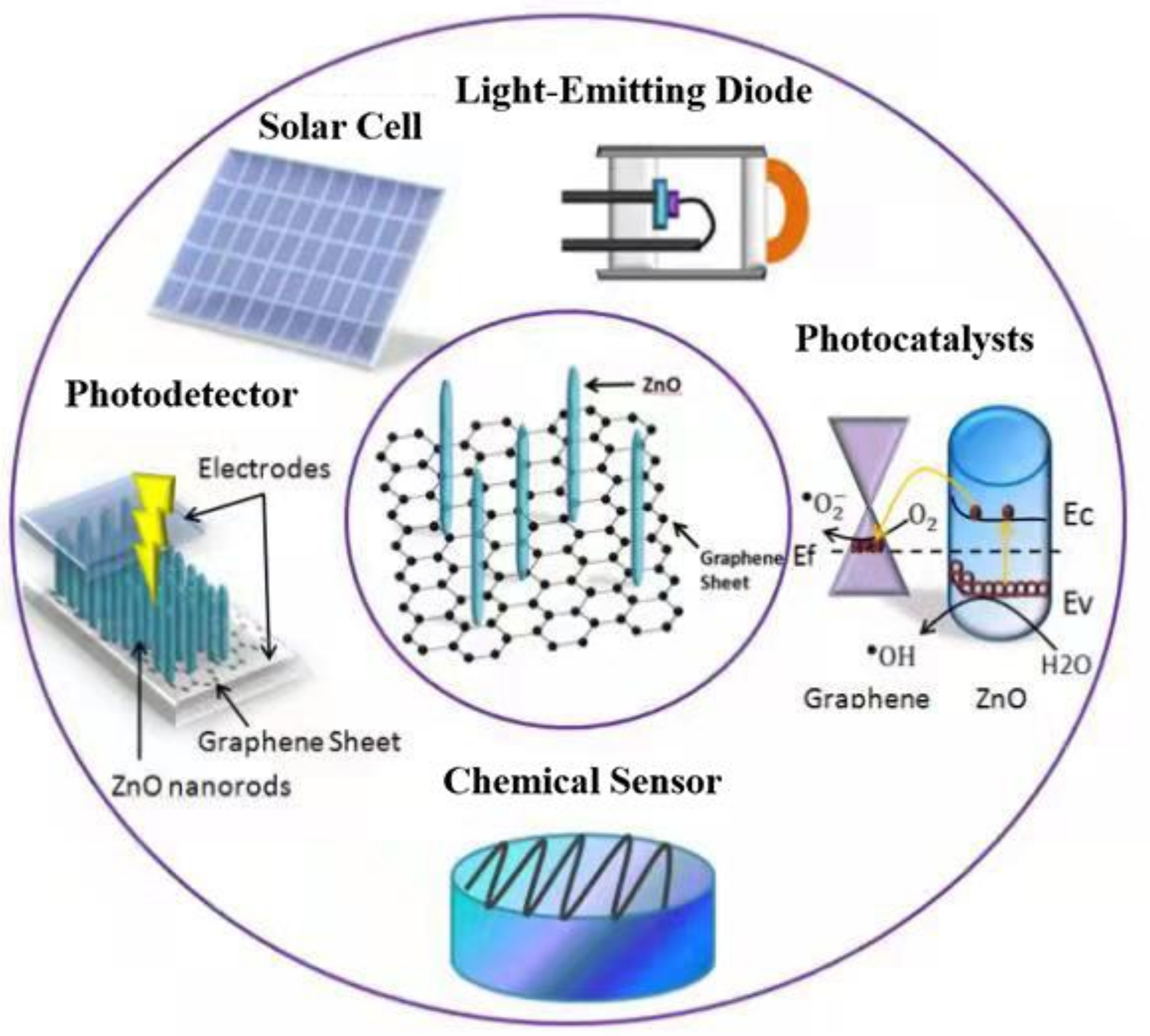
:1. Introduction
2. The Principles of Photocatalytic and Photoresponse Properties of Nanocomposites
2.1. The Photocatalytic Principles of ZnO and Related Nanocomposites
2.2. The Photoresponse Principles of ZnO and Related Nanocomposites
3. Synthesis and Structural Characteristics of ZnO–Graphene Composites
3.1. ZnO–0D Graphene Quantum Dot Composite
3.2. ZnO–2D Graphene Composites
3.2.1. Changing the ZnO–2D Graphene Structure
3.2.2. ZnO–2D-Graphene-Doped Substances
3.2.3. ZnO–2D Graphene with Both Structural Change and Doping
3.3. ZnO–3D Graphene Foam
3.3.1. ZnO Quantum Dot–3D Graphene Network
3.3.2. ZnO Nanowire–3D Graphene Network
3.3.3. ZnO Nanorod–3D Graphene Network
4. Photocatalysis
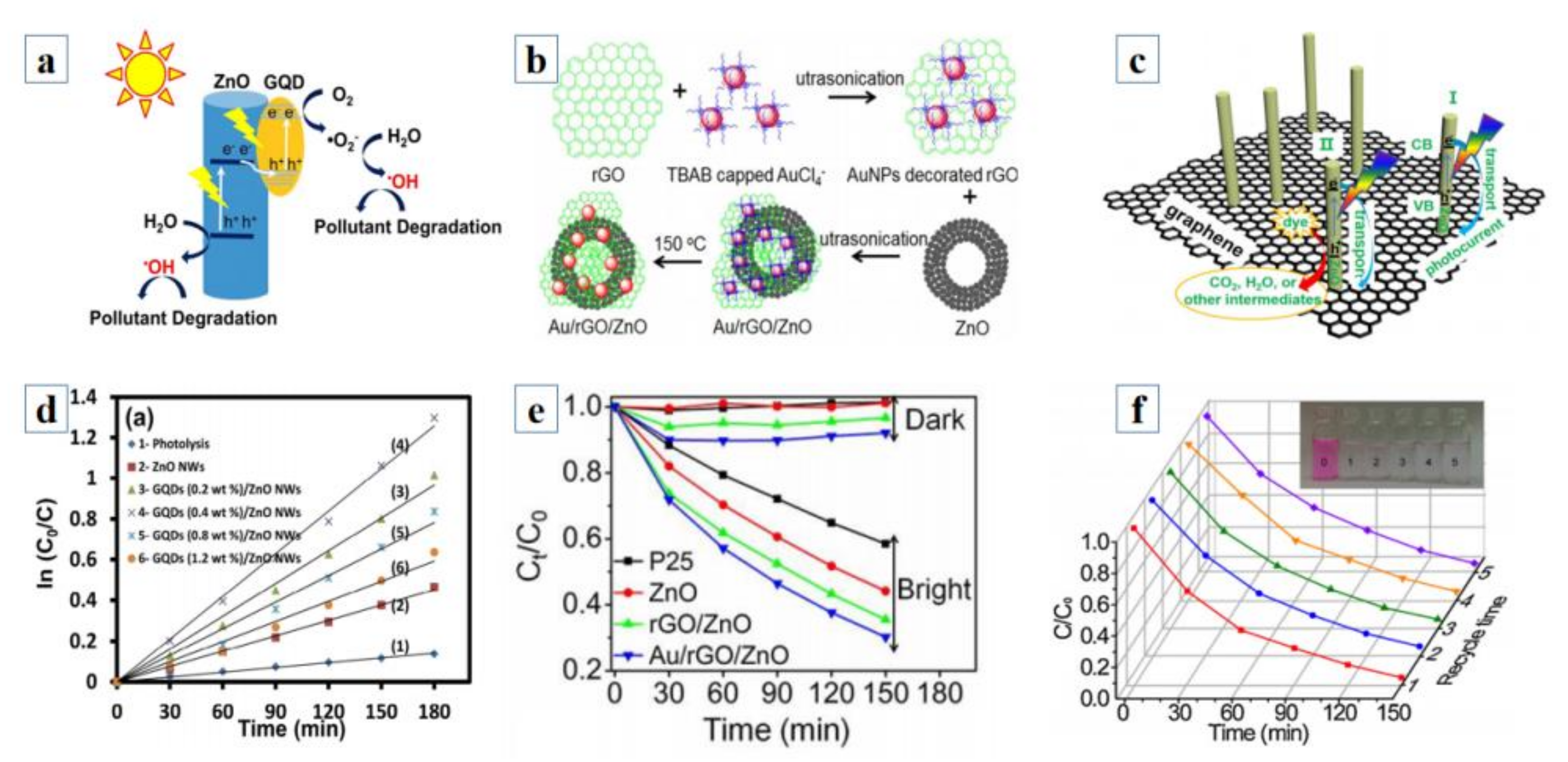
4.1. ZnO–0D Graphene Quantum Dot Photocatalysts
4.2. ZnO–2D Graphene Sheet Photocatalysts
4.2.1. ZnO–2D Graphene Doped with Metals
4.2.2. ZnO–2D Graphene Doped with Compounds
4.2.3. ZnO–2D Graphene Doped with Carbon Nanotubes
4.3. ZnO–3D Graphene Photocatalysts
5. Photodetection
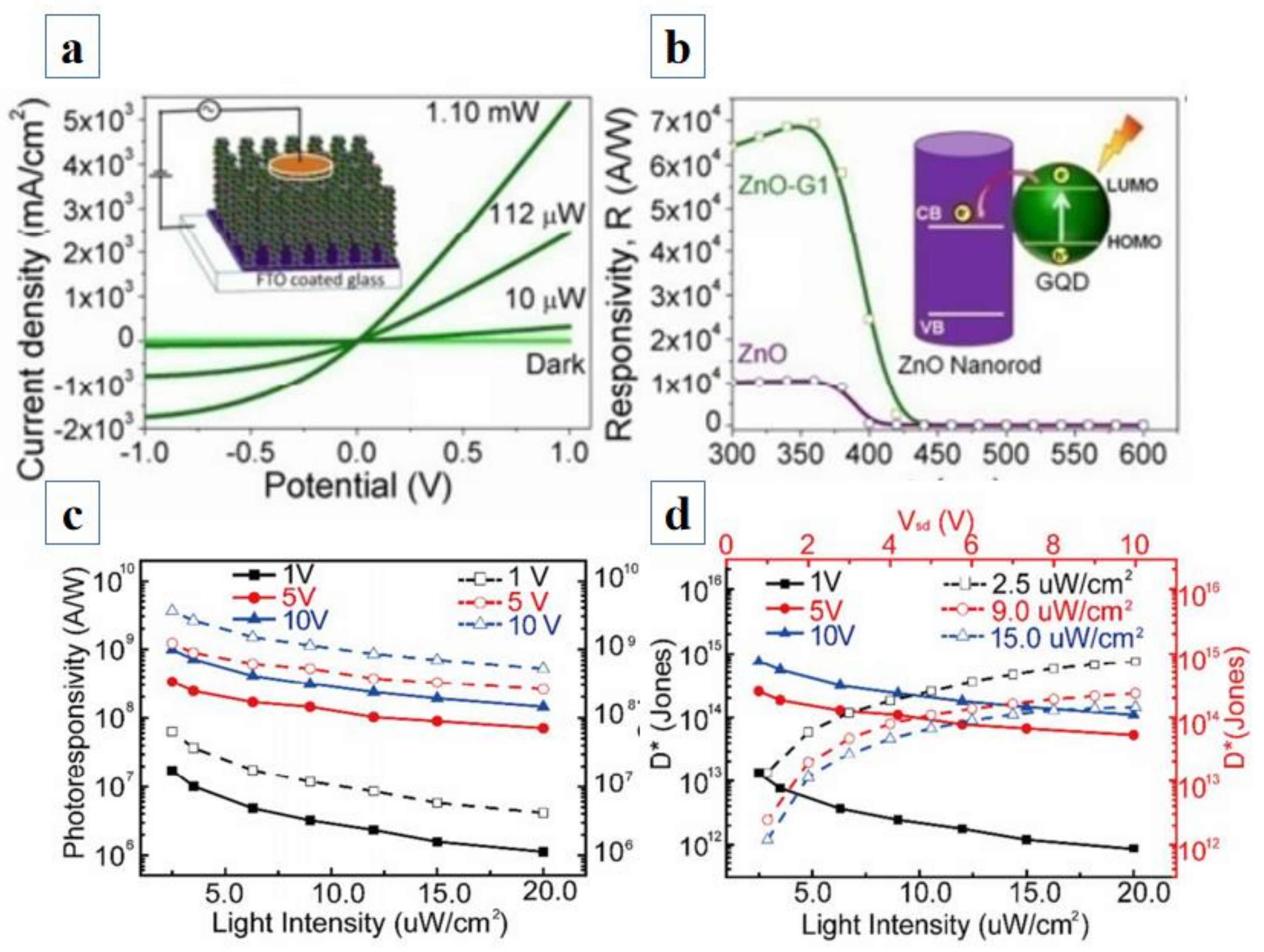
5.1. ZnO–0D Graphene Quantum Dot Photodetector
5.2. ZnO–2D Graphene Photodetectors
5.2.1. ZnO Nanowire–Graphene Sheet Photodetectors
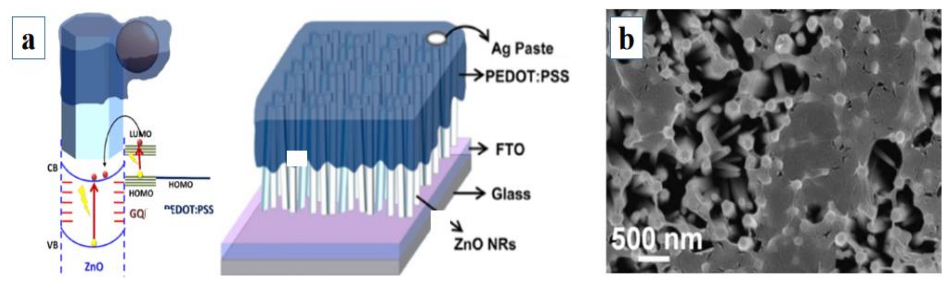
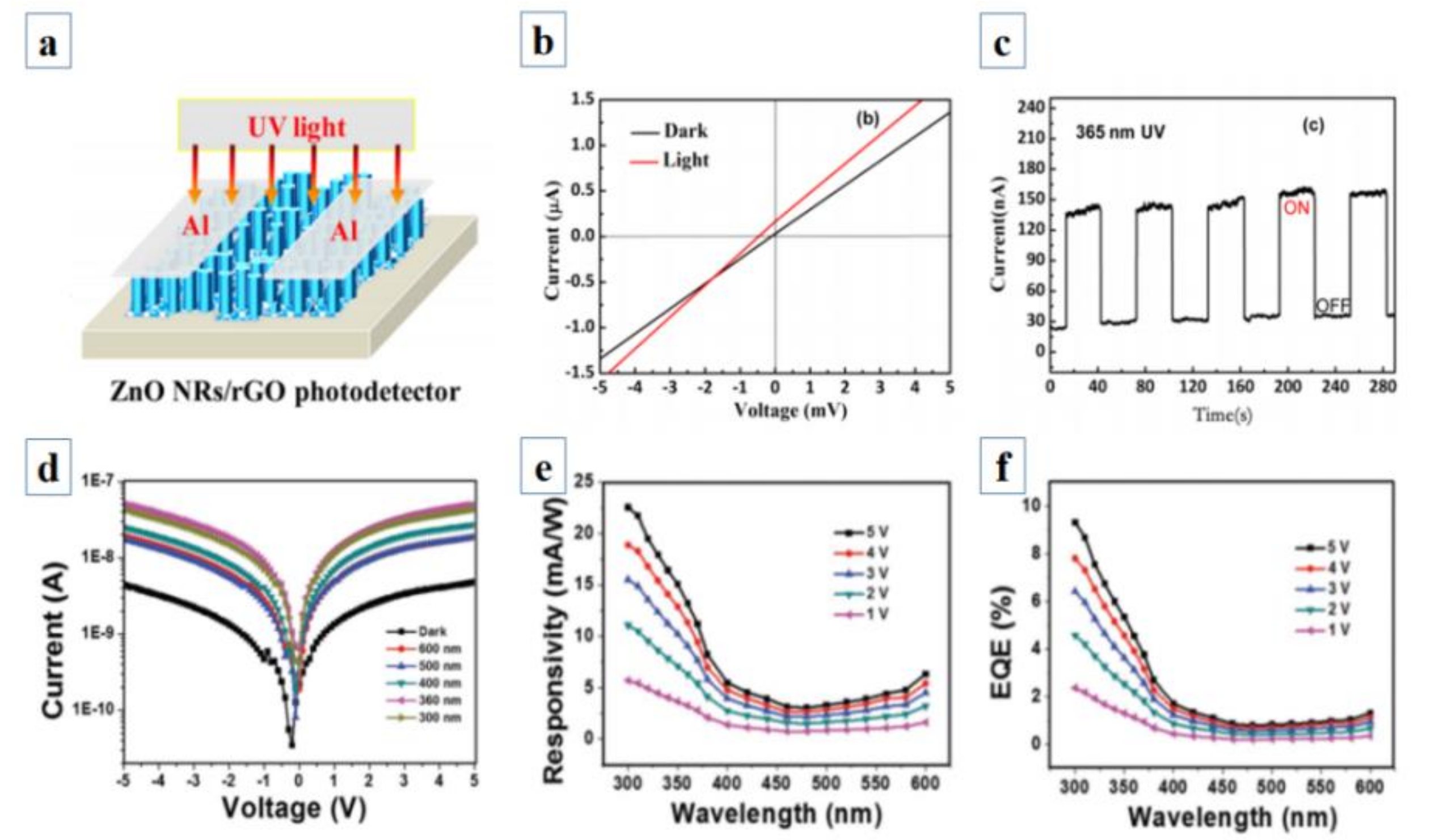
5.2.2. ZnO Nanorod–Graphene Sheet Photodetectors
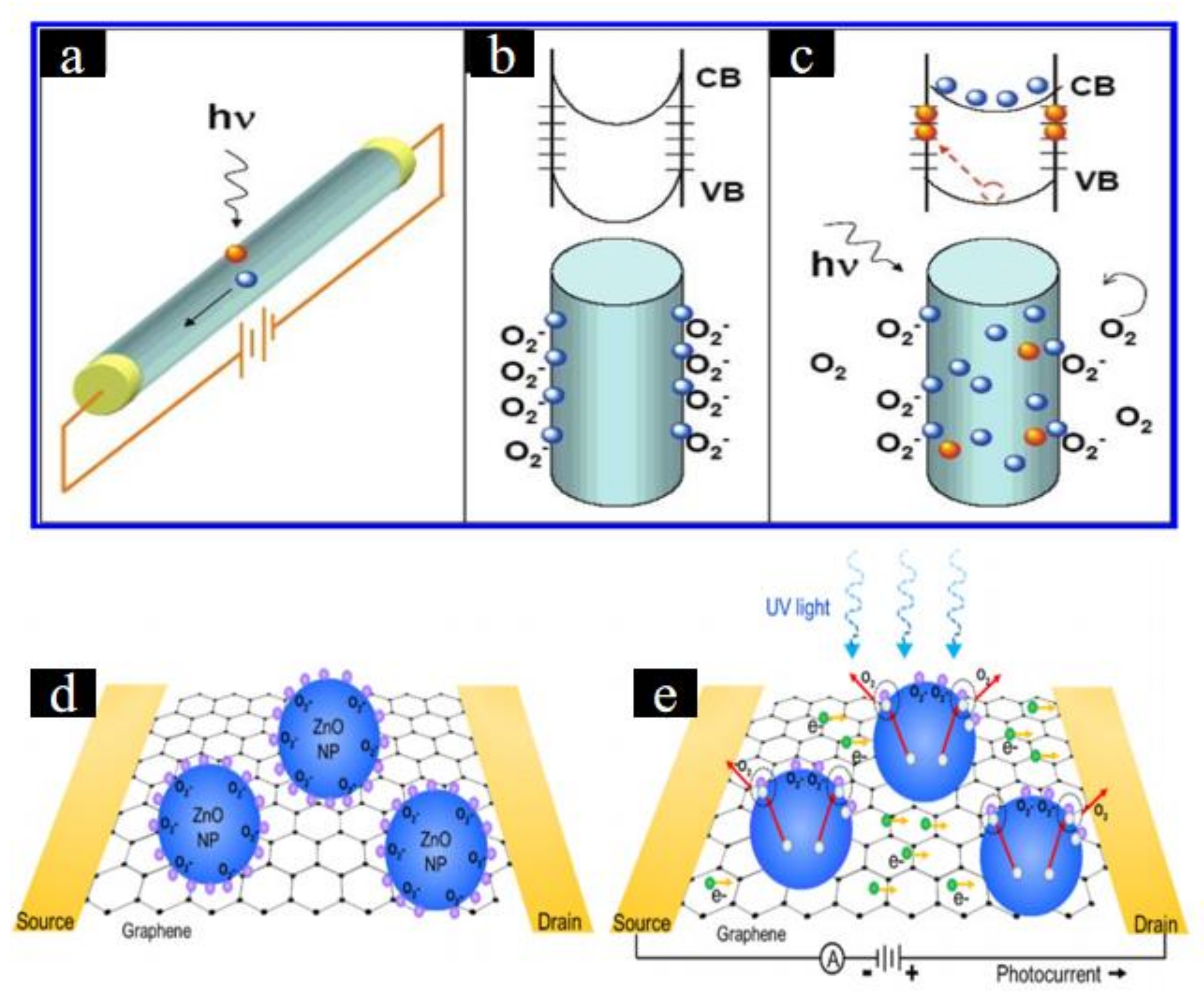
5.2.3. ZnO Nanoparticle–Graphene Sheet Photodetectors
5.3. ZnO–3D Graphene Photodetector
6. Conclusions and Prospects
Author Contributions
Funding
Conflicts of Interest
References
- Liu, X.; Gu, L.; Zhang, Q.; Wu, J.; Long, Y.; Fan, Z. All-printable band-edge modulated ZnO nanowire photodetectors with ultra-high detectivity. Nat. Commun. 2014, 5, 4007. [Google Scholar] [CrossRef] [PubMed] [Green Version]
- Yang, H.; Li, J.; Yu, D.; Li, L. Seed/Catalyst Free Growth and Self-Powered Photoresponse of Vertically Aligned ZnO Nanorods on Reduced Graphene Oxide Nanosheets. Cryst. Growth Des. 2016, 16, 4831–4838. [Google Scholar] [CrossRef]
- Hmar, J.J.L.; Majumder, T.; Dhar, S.; Mondal, S.P. Sulfur and Nitrogen co-doped graphene quantum dot decorated ZnO nanorod/polymer hybrid flexible device for photosensing applications. Thin Solid Films 2016, 612, 274–283. [Google Scholar] [CrossRef]
- Qian, L.; Zheng, Y.; Xue, J.; Holloway, P.H. Stable and efficient quantum-dot light-emitting diodes based on solution-processed multilayer structures. Nat. Photonics 2011, 5, 543–548. [Google Scholar] [CrossRef]
- Lim, J.H.; Kang, C.K.; Kim, K.K.; Park, I.K.; Hwang, D.K.; Park, S.J. UV Electroluminescence Emission from ZnO Light-Emitting Diodes Grown by High-Temperature Radiofrequency Sputtering. Adv. Mater. 2006, 18, 2720–2724. [Google Scholar] [CrossRef]
- Son, D.I.; Kwon, B.W.; Park, D.H.; Seo, W.-S.; Yi, Y.; Angadi, B.; Lee, C.-L.; Choi, W.K. Emissive ZnO–graphene quantum dots for white-light-emitting diodes. Nat. Nanotechnol. 2012, 7, 465–471. [Google Scholar] [CrossRef]
- Li, X.; Chen, Y.; Kumar, A.; Mahmoud, A.; Nychka, J.A.; Chung, H.-J. Sponge-Templated Macroporous Graphene Network for Piezoelectric ZnO Nanogenerator. ACS Appl. Mater. Interfaces 2015, 7, 20753–20760. [Google Scholar] [CrossRef]
- Yang, Y.; Pradel, K.C.; Jing, Q.; Wu, J.M.; Zhang, F.; Zhou, Y.; Zhang, Y.; Wang, Z.L. Thermoelectric Nanogenerators Based on Single Sb-Doped ZnO Micro/Nanobelts. ACS Nano 2012, 6, 6984–6989. [Google Scholar] [CrossRef]
- Yin, Z.; Wu, S.; Zhou, X.; Huang, X.; Zhang, Q.; Boey, F.; Zhang, H. Electrochemical Deposition of ZnO Nanorods on Transparent Reduced Graphene Oxide Electrodes for Hybrid Solar Cells. Small 2010, 6, 307–312. [Google Scholar] [CrossRef]
- Wibowo, A.; Marsudi, M.A.; Amal, M.I.; Ananda, M.B.; Stephanie, R.; Ardy, H.; Diguna, L.J. ZnO nanostructured materials for emerging solar cell applications. RSC Adv. 2020, 10, 42838–42859. [Google Scholar] [CrossRef]
- Guo, J.; Zhang, J.; Zhu, M.; Ju, D.; Xu, H.; Cao, B. High-performance gas sensor based on ZnO nanowires functionalized by Au nanoparticles. Sens. Actuators B Chem. 2014, 199, 339–345. [Google Scholar] [CrossRef]
- Xia, Y.; Wang, J.; Xu, J.-L.; Li, X.; Xie, D.; Xiang, L.; Komarneni, S. Confined Formation of Ultrathin ZnO Nanorods/Reduced Graphene Oxide Mesoporous Nanocomposites for High-Performance Room-Temperature NO2 Sensors. ACS Appl. Mater. Interfaces 2016, 8, 35454–35463. [Google Scholar] [CrossRef]
- Yue, H.Y.; Huang, S.; Chang, J.; Heo, C.; Yao, F.; Adhikari, S.; Gunes, F.; Liu, L.C.; Lee, T.H.; Oh, E.S.; et al. ZnO Nanowire Arrays on 3D Hierachical Graphene Foam: Biomarker Detection of Parkinson’s Disease. ACS Nano 2014, 8, 1639–1646. [Google Scholar] [CrossRef]
- Haldavnekar, R.; Venkatakrishnan, K.; Tan, B. Non plasmonic semiconductor quantum SERS probe as a pathway for in vitro cancer detection. Nat. Commun. 2018, 9, 3065. [Google Scholar] [CrossRef] [Green Version]
- Bu, Y.; Chen, Z.; Li, W.; Hou, B. Highly Efficient Photocatalytic Performance of Graphene–ZnO Quasi-Shell–Core Composite Material. ACS Appl. Mater. Interfaces 2013, 5, 12361–12368. [Google Scholar] [CrossRef]
- Ezeigwe, E.R.; Tan, M.T.T.; Khiew, P.S.; Siong, C.W. One-step green synthesis of graphene/ZnO nanocomposites for electrochemical capacitors. Ceram. Int. 2015, 41, 715–724. [Google Scholar] [CrossRef]
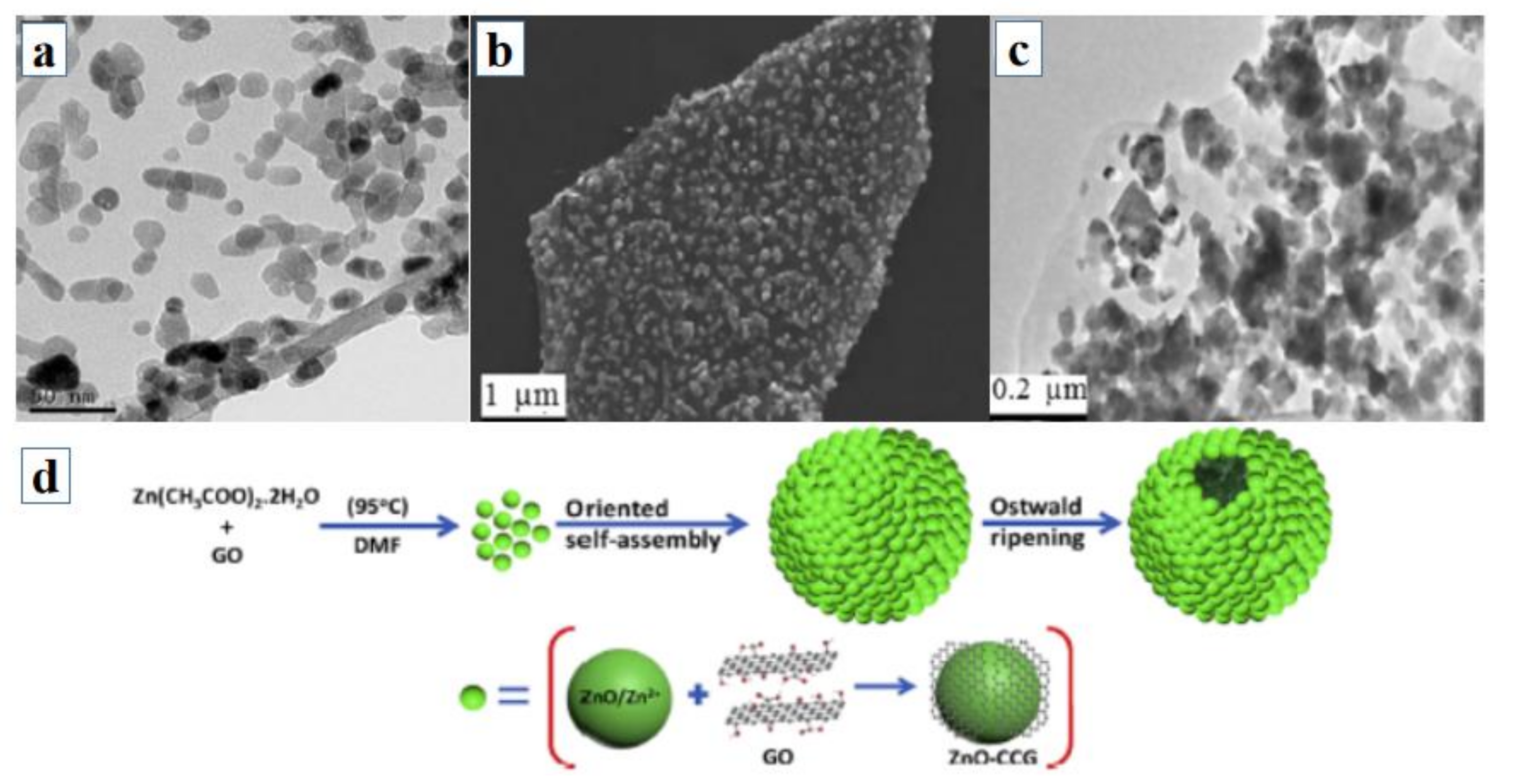
- Bera, S.; Pal, M.; Naskar, A.; Jana, S. Hierarchically structured ZnO-graphene hollow microspheres towards effective reusable adsorbent for organic pollutant via photodegradation process. J. Alloy. Compd. 2016, 669, 177–186. [Google Scholar] [CrossRef]
- Xu, S.; Fu, L.; Pham, T.S.H.; Yu, A.; Han, F.; Chen, L. Preparation of ZnO flower/reduced graphene oxide composite with enhanced photocatalytic performance under sunlight. Ceram. Int. 2015, 41, 4007–4013. [Google Scholar] [CrossRef]
- Han, C.; Chen, Z.; Zhang, N.; Colmenares, J.C.; Xu, Y.-J. Hierarchically CdS Decorated 1D ZnO Nanorods-2D Graphene Hybrids: Low Temperature Synthesis and Enhanced Photocatalytic Performance. Adv. Funct. Mater. 2015, 25, 221–229. [Google Scholar] [CrossRef]
- Li, W.; Fang, X.; Wang, D.; Tian, F.; Wang, H.; Fang, D.; Li, J.; Chu, X.; Zhao, H.; Wang, D.; et al. Band and optical properties of arsenene and antimonene lateral heterostructure by first-principles calculations. Phys. E Low-Dimens. Syst. Nanostructures 2021, 134, 114933. [Google Scholar] [CrossRef]
- Tian, F.; Wang, D.; Tan, F.; Fang, X.; Li, W.; Wang, H.; Wang, D.; Zhao, H.; Fang, D.; Wei, Z.; et al. Strain-Dependent Band Structures and Electronic Properties in Sb/Bi Lateral Heterostructures Calculated by First Principles. Phys. Status Solidi –Rapid Res. Lett. 2021, 15, 2100148. [Google Scholar] [CrossRef]
- Wang, D.; Wang, F.; Wang, Y.; Fan, Y.; Zhao, B.; Zhao, D. Interfacial Emission Adjustment in ZnO Quantum Dots/p-GaN Heterojunction Light-Emitting Diodes. J. Phys. Chem. C 2015, 119, 2798–2803. [Google Scholar] [CrossRef]
- Wang, Y.; Fang, X.; Li, R.; Li, Y.; Yao, B.; Wang, D.; Tang, J.; Fang, D.; Wang, X.; Wang, X.; et al. Surface sulfurization of ZnO/ZnS core shell nanowires and shell layers dependent optical properties. J. Mater. Sci. Mater. Electron. 2018, 29, 7924–7929. [Google Scholar] [CrossRef]
- Fang, X.; Wei, Z.; Yang, Y.; Chen, R.; Li, Y.; Tang, J.; Fang, D.; Jia, H.; Wang, D.; Fan, J.; et al. Ultraviolet Electroluminescence from ZnS@ZnO Core–Shell Nanowires/p-GaN Introduced by Exciton Localization. ACS Appl. Mater. Interfaces 2016, 8, 1661–1666. [Google Scholar] [CrossRef]
- Xu, Y.; Ma, G.; Wang, G.; Shi, L.; Zhang, H.; Jin, L.; Ma, X.; Zou, Y.; Yin, J.; Li, Y. Interface State Luminescence and Sub-Bandgap Absorption Based on CuGaO2 Nanoplates/ZnO Nanowires Heterostructure Arrays. Phys. Status Solidi 2018, 255, 1800391. [Google Scholar] [CrossRef]
- Xu, Y.; Li, Y.; Shi, L.; Li, D.; Zhang, H.; Jin, L.; Xu, L.; Ma, X.; Zou, Y.; Yin, J. Reverse-bias-driven whispering gallery mode lasing from individual ZnO microwire/p-Si heterojunction. Nanoscale 2018, 10, 5302–5308. [Google Scholar] [CrossRef] [PubMed]
- Kumar, S.; Sharma, V.; Bhattacharyya, K.; Krishnan, V. N-doped ZnO–MoS2 binary heterojunctions: The dual role of 2D MoS2 in the enhancement of photostability and photocatalytic activity under visible light irradiation for tetracycline degradation. Mater. Chem. Front. 2017, 1, 1093–1106. [Google Scholar] [CrossRef]
- Kudo, A.; Miseki, Y. Heterogeneous photocatalyst materials for water splitting. Chem. Soc. Rev. 2009, 38, 253–278. [Google Scholar] [CrossRef] [PubMed]
- Allen, M.J.; Tung, V.C.; Kaner, R.B. Honeycomb Carbon: A Review of Graphene. Chem. Rev. 2010, 110, 132–145. [Google Scholar] [CrossRef]
- Luan, V.H.; Tien, H.N.; Hur, S.H. Fabrication of 3D structured ZnO nanorod/reduced graphene oxide hydrogels and their use for photo-enhanced organic dye removal. J. Colloid Interface Sci. 2015, 437, 181–186. [Google Scholar] [CrossRef]
- Song, C.; Yin, X.; Han, M.; Li, X.; Hou, Z.; Zhang, L.; Cheng, L. Three-dimensional reduced graphene oxide foam modified with ZnO nanowires for enhanced microwave absorption properties. Carbon 2017, 116, 50–58. [Google Scholar] [CrossRef]
- Kumar, S.; Dhiman, A.; Sudhagar, P.; Krishnan, V. ZnO-graphene quantum dots heterojunctions for natural sunlight-driven photocatalytic environmental remediation. Appl. Surf. Sci. 2018, 447, 802–815. [Google Scholar] [CrossRef] [Green Version]
- Soci, C.; Zhang, A.; Xiang, B.; Dayeh, S.A.; Aplin, D.P.R.; Park, J.; Bao, X.Y.; Lo, Y.H.; Wang, D. ZnO Nanowire UV Photodetectors with High Internal Gain. Nano Lett. 2007, 7, 1003–1009. [Google Scholar] [CrossRef] [PubMed]
- Charipar, K.; Kim, H.; Piqué, A.; Charipar, N. ZnO Nanoparticle/Graphene Hybrid Photodetectors via Laser Fragmentation in Liquid. Nanomaterials 2020, 10, 1648. [Google Scholar] [CrossRef] [PubMed]
- Wang, J.; Li, Y.; Ge, J.; Zhang, B.-P.; Wan, W. Improving photocatalytic performance of ZnO via synergistic effects of Ag nanoparticles and graphene quantum dots. Phys. Chem. Chem. Phys. 2015, 17, 18645–18652. [Google Scholar] [CrossRef] [PubMed]
- Zeng, Z.; Wang, D.; Wang, J.; Jiao, S.; Liu, D.; Zhang, B.; Zhao, C.; Liu, Y.; Liu, Y.; Xu, Z.; et al. Broadband Detection Based on 2D Bi2Se3/ZnO Nanowire Heterojunction. Crystals 2021, 11, 169. [Google Scholar] [CrossRef]
- Dhar, S.; Majumder, T.; Mondal, S.P. Graphene Quantum Dot-Sensitized ZnO Nanorod/Polymer Schottky Junction UV Detector with Superior External Quantum Efficiency, Detectivity, and Responsivity. ACS Appl. Mater. Interfaces 2016, 8, 31822–31831. [Google Scholar] [CrossRef] [PubMed]
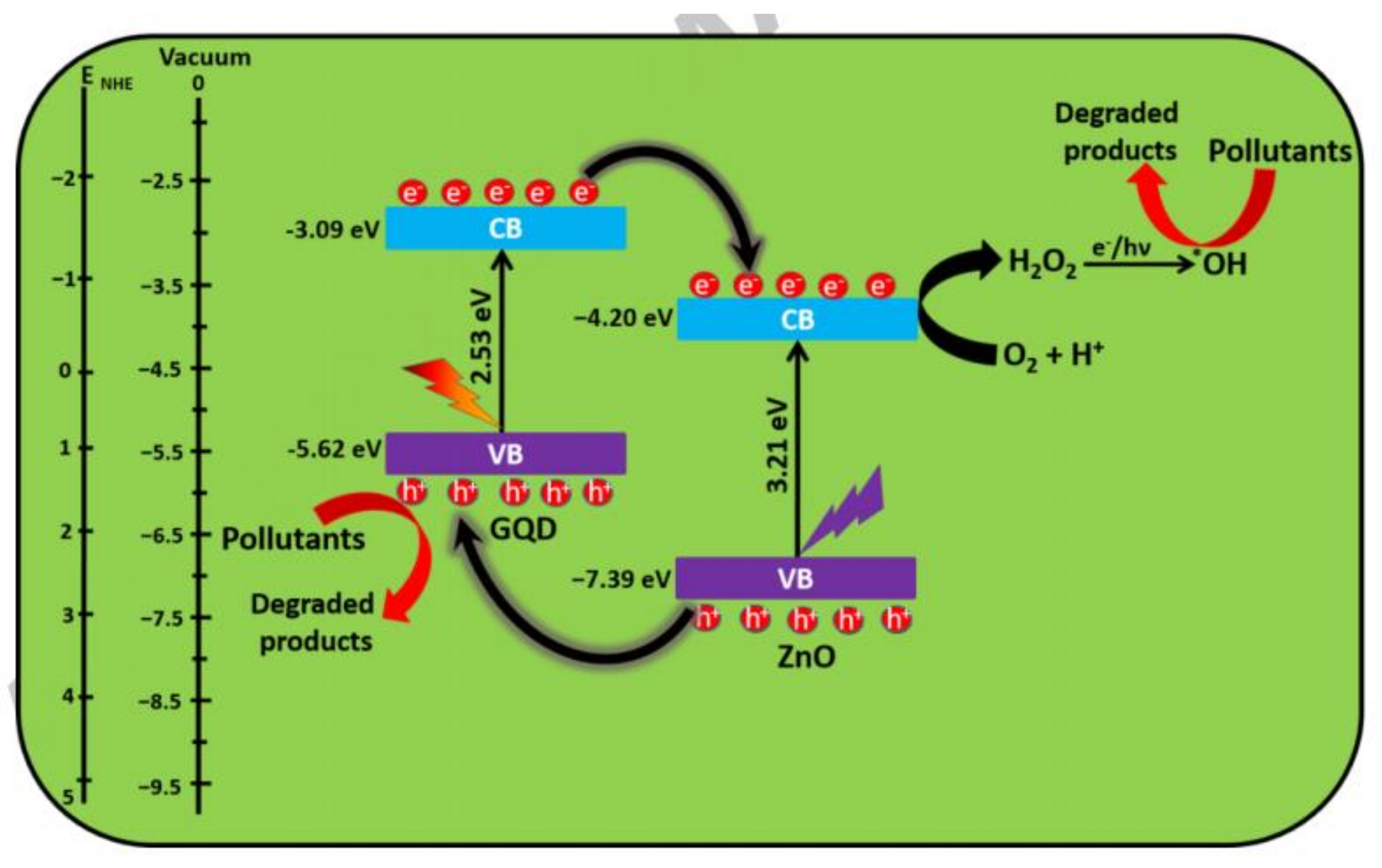
- Ebrahimi, M.; Samadi, M.; Yousefzadeh, S.; Soltani, M.; Rahimi, A.; Chou, T.-C.; Chen, L.-C.; Chen, K.-H.; Moshfegh, A.Z. Improved Solar-Driven Photocatalytic Activity of Hybrid Graphene Quantum Dots/ZnO Nanowires: A Direct Z-Scheme Mechanism. ACS Sustain. Chem. Eng. 2017, 5, 367–375. [Google Scholar] [CrossRef]
- Ghosh, D.; Kapri, S.; Bhattacharyya, S. Phenomenal Ultraviolet Photoresponsivity and Detectivity of Graphene Dots Immobilized on Zinc Oxide Nanorods. ACS Appl. Mater. Interfaces 2016, 8, 35496–35504. [Google Scholar] [CrossRef]
- Khoa, N.T.; Kim, S.W.; Yoo, D.-H.; Cho, S.; Kim, E.J.; Hahn, S.H. Fabrication of Au/Graphene-Wrapped ZnO-Nanoparticle-Assembled Hollow Spheres with Effective Photoinduced Charge Transfer for Photocatalysis. ACS Appl. Mater. Interfaces 2015, 7, 3524–3531. [Google Scholar] [CrossRef]
- Lv, T.; Pan, L.; Liu, X.; Sun, Z. Enhanced photocatalytic degradation of methylene blue by ZnO–reduced graphene oxide–carbon nanotube composites synthesized via microwave-assisted reaction. Catal. Sci. Technol. 2012, 2, 2297–2301. [Google Scholar] [CrossRef]
- Wu, J.; Shen, X.; Jiang, L.; Wang, K.; Chen, K. Solvothermal synthesis and characterization of sandwich-like graphene/ZnO nanocomposites. Appl. Surf. Sci. 2010, 256, 2826–2830. [Google Scholar] [CrossRef]
- Xu, Q.; Cheng, Q.; Zhong, J.; Cai, W.; Zhang, Z.; Wu, Z.; Zhang, F. A metal–semiconductor–metal detector based on ZnO nanowires grown on a graphene layer. Nanotechnology 2014, 25, 055501. [Google Scholar] [CrossRef] [PubMed]
- Boruah, B.; Mukherjee, A.; Misra, A. Sandwiched assembly of ZnO nanowires between graphene layers for a self-powered and fast responsive ultraviolet photodetector. Nanotechnology 2016, 27, 095205. [Google Scholar] [CrossRef] [PubMed]
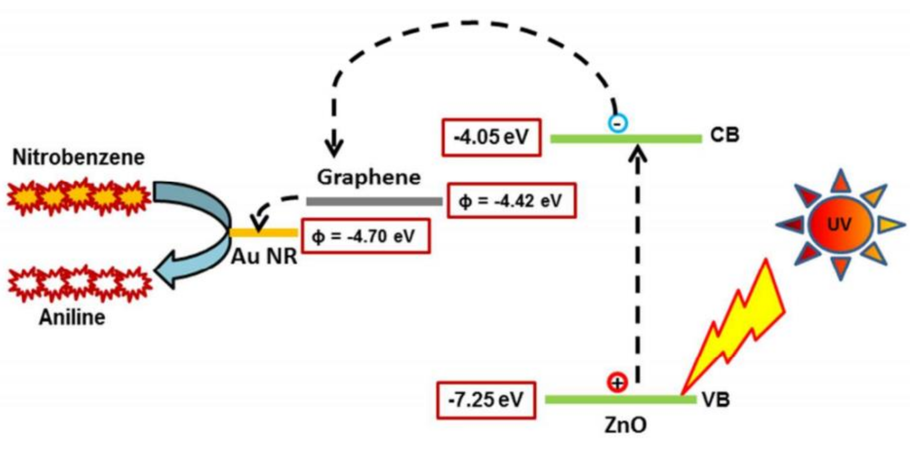
- Roy, P.; Periasamy, A.P.; Liang, C.-T.; Chang, H.-T. Synthesis of Graphene-ZnO-Au Nanocomposites for Efficient Photocatalytic Reduction of Nitrobenzene. Environ. Sci. Technol. 2013, 47, 6688–6695. [Google Scholar] [CrossRef] [PubMed]
- Dou, P.; Tan, F.; Wang, W.; Sarreshteh, A.; Qiao, X.; Qiu, X.; Chen, J. One-step microwave-assisted synthesis of Ag/ZnO/graphene nanocomposites with enhanced photocatalytic activity. J. Photochem. Photobiol. A Chem. 2015, 302, 17–22. [Google Scholar] [CrossRef]
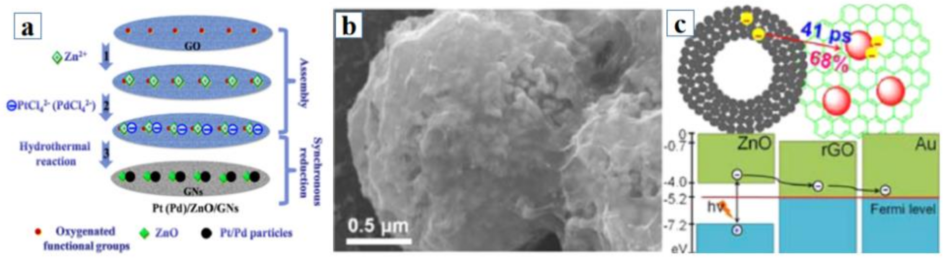
- Li, Z.; Ye, L.; Lei, F.; Wang, Y.; Xu, S.; Lin, S. Enhanced electro-photo synergistic catalysis of Pt (Pd)/ZnO/graphene composite for methanol oxidation under visible light irradiation. Electrochim. Acta 2016, 188, 450–460. [Google Scholar] [CrossRef]
- Bhirud, A.; Sathaye, S.; Waichal, R.; Park, C.-J.; Kale, B. In situ preparation of N–ZnO/graphene nanocomposites: Excellent candidate as a photocatalyst for enhanced solar hydrogen generation and high performance supercapacitor electrode. J. Mater. Chem. A 2015, 3, 17050–17063. [Google Scholar] [CrossRef]
- Tayyebi, A.; outokesh, M.; Tayebi, M.; Shafikhani, A.; Şengör, S.S. ZnO quantum dots-graphene composites: Formation mechanism and enhanced photocatalytic activity for degradation of methyl orange dye. J. Alloy. Compd. 2016, 663, 738–749. [Google Scholar] [CrossRef] [Green Version]
- Boruah, B.D.; Mukherjee, A.; Sridhar, S.; Misra, A. Highly Dense ZnO Nanowires Grown on Graphene Foam for Ultraviolet Photodetection. ACS Appl. Mater. Interfaces 2015, 7, 10606–10611. [Google Scholar] [CrossRef]
- Shao, D.; Gao, J.; Xin, G.; Wang, Y.; Li, L.; Shi, J.; Lian, J.; Koratkar, N.; Sawyer, S. Cl-Doped ZnO Nanowire Arrays on 3D Graphene Foam with Highly Efficient Field Emission and Photocatalytic Properties. Small 2015, 11, 4785–4792. [Google Scholar] [CrossRef]
- Cai, R.; Wu, J.-G.; Sun, L.; Liu, Y.-J.; Fang, T.; Zhu, S.; Li, S.-Y.; Wang, Y.; Guo, L.-F.; Zhao, C.-E.; et al. 3D graphene/ZnO composite with enhanced photocatalytic activity. Mater. Des. 2016, 90, 839–844. [Google Scholar] [CrossRef]
- Men, X.; Chen, H.; Chang, K.; Fang, X.; Wu, C.; Qin, W.; Yin, S. Three-dimensional free-standing ZnO/graphene composite foam for photocurrent generation and photocatalytic activity. Appl. Catal. B Environ. 2016, 187, 367–374. [Google Scholar] [CrossRef]
- Zhang, C.; Zhang, J.; Su, Y.; Xu, M.; Yang, Z.; Zhang, Y. ZnO nanowire/reduced graphene oxide nanocomposites for significantly enhanced photocatalytic degradation of Rhodamine 6G. Phys. E Low-Dimens. Syst. Nanostruct. 2014, 56, 251–255. [Google Scholar] [CrossRef]
- Moussa, H.; Girot, E.; Mozet, K.; Alem, H.; Medjahdi, G.; Schneider, R. ZnO rods/reduced graphene oxide composites prepared via a solvothermal reaction for efficient sunlight-driven photocatalysis. Appl. Catal. B Environ. 2016, 185, 11–21. [Google Scholar] [CrossRef]
- Bai, X.; Sun, C.; Liu, D.; Luo, X.; Li, D.; Wang, J.; Wang, N.; Chang, X.; Zong, R.; Zhu, Y. Photocatalytic degradation of deoxynivalenol using graphene/ZnO hybrids in aqueous suspension. Appl. Catal. B: Environ. 2017, 204, 11–20. [Google Scholar] [CrossRef] [Green Version]
- Pawar, R.C.; Lee, C.S. Single-step sensitization of reduced graphene oxide sheets and CdS nanoparticles on ZnO nanorods as visible-light photocatalysts. Appl. Catal. B Environ. 2014, 144, 57–65. [Google Scholar] [CrossRef]
- Gong, M.; Liu, Q.; Cook, B.; Kattel, B.; Wang, T.; Chan, W.-L.; Ewing, D.; Casper, M.; Stramel, A.; Wu, J.Z. All-Printable ZnO Quantum Dots/Graphene van der Waals Heterostructures for Ultrasensitive Detection of Ultraviolet Light. ACS Nano 2017, 11, 4114–4123. [Google Scholar] [CrossRef] [PubMed]
- Cook, B.; Liu, Q.; Liu, J.; Gong, M.; Ewing, D.; Casper, M.; Stramel, A.; Wu, J. Facile zinc oxide nanowire growth on graphene via a hydrothermal floating method: Towards Debye length radius nanowires for ultraviolet photodetection. J. Mater. Chem. C 2017, 5, 10087–10093. [Google Scholar] [CrossRef]
- Liu, S.; Liao, Q.; Lu, S.; Zhang, Z.; Zhang, G.; Zhang, Y. Strain Modulation in Graphene/ZnO Nanorod Film Schottky Junction for Enhanced Photosensing Performance. Adv. Funct. Mater. 2016, 26, 1347–1353. [Google Scholar] [CrossRef]
- Tang, R.; Han, S.; Teng, F.; Hu, K.; Zhang, Z.; Hu, M.; Fang, X. Size-Controlled Graphene Nanodot Arrays/ZnO Hybrids for High-Performance UV Photodetectors. Adv. Sci. 2018, 5, 1700334. [Google Scholar] [CrossRef] [PubMed] [Green Version]
- Liu, H.; Sun, Q.; Xing, J.; Zheng, Z.; Zhang, Z.; Lü, Z.; Zhao, K. Fast and Enhanced Broadband Photoresponse of a ZnO Nanowire Array/Reduced Graphene Oxide Film Hybrid Photodetector from the Visible to the Near-Infrared Range. ACS Appl. Mater. Interfaces 2015, 7, 6645–6651. [Google Scholar] [CrossRef] [PubMed]


| Structure | Diameter of ZnO (Synthesis Method) | Graphene Content | Mass/Concentration of Sample | Target Pollutant | Detection Light | Performance | Ref. |
|---|---|---|---|---|---|---|---|
| Ag nanoparticles–0D graphene –ZnO flowers | \ | 0.1 mg·mL−1 GQDs aqueous solution | \ | Rhodamine B (RhB) | 500 W visible light | Efficiency of 57.49% after 8 h of illumination | [35] |
| ZnO nanowires–0D graphene | 170–250 nm (anodization) | 0.4 wt% GQDs | 15 mg | 40 mL 10−5 M methylene blue (MB) solution | 800 W·m−2 solar light | First-order degradation rate constant (k) = 0.007 min−1 (180 min illumination) | [38] |
| ZnO nanoparticles–2D graphene core-shell | 500 nm (one-step wet chemical method) | 10 mg graphene oxide | 0.1 g | 100 mL 10 mg·L−1 RhB solution | 300 W Xe arc lamp | Achieved 78.9% degradation within 10 min and finished after 20 min | [15] |
| ZnO nanowires–2D graphene | 1.8 um (33.8 um length) (PVP-assisted water solution thermal method) | \ | 10 mg | 100 mL 10 mg/L Rhodamine 6G (Rh6G) solution | A 150 W mercury lamp with wavelength of 365 nm | Achieved 80% efficiency after 5 min and 98% after 10 min | [54] |
| Micro-sized ZnO flowers–2D graphene | Simple one-pot hydrothermal method | 2% graphene oxide | 50 mg | 40 mL 15 mg·mL−1 MB solution | a 100 W UV lamp | Completed in 60 min | [18] |
| ZnO quantum dots–2D graphene | 3 nm (simple chemical method) | 5% graphing loading | 50 mg | 100 mL of a 1.5 × 10⁻⁴ M aqueous methyl orange (MO) solution (pH = 6.5) | 100 W mercury lamp with the wavelength of 365 nm as the UV source; a 175 W metal halide lamp (λ > 420 nm) as the visible light source | degradation rate = 0.11 min−1 under UV light; degradation rate = 0.35 h−1 under visible light | [49] |
| ZnO nanorods–2D graphene | 16 nm (solvothermal method) | 10 wt% graphene | 60 mg | 50 mL 10 mg·L−1 Orange II solution | 5 mW·cm−2 solar light | Efficiency of 99% after 150 min illumination | [55] |
| Hierarchically structured ZnO–2D graphene hollow microspheres | Individual ZnO nanoparticles: 12 nm; microspheres: over 50 nm (low-temperature solution method) | Graphene oxide to zinc acetate dihydrate weight ratio = 0.032 | 1 mg·mL−1 | 10−5 M RhB solution, 10−5 M MO solution, 10−4 M phenols solution | UV light with wavelength of 254 nm | Completed in 40 min; constant first-order rate = 6.2 × 10⁻² min−1; 1.5 × 10⁻² min−1 | [17] |
| ZnO nanoparticles–2D graphene | 10–20 nm (a simple one-step hydrothermal method) | 0.3 wt% graphene | 25 mg | 50 mL 15 ppm deoxynivalenol (DON) aqueous solute | UV light with wavelength of 254 nm and 365 nm | Reaction rate constant: 0.10411 min−1 under 365 nm light; 0.024 min−1 under 254 nm light | [56] |
| ZnO nanorods–carbon nanotubes–2D graphene | 40–60 nm (microwave-assisted hydrothermal method) | \ | 1.5 g·L−1 | 100 mL 5 mg·L−1 MB solution | 500 W Hg lamp produced UV light with wavelength of 365 nm | 96% efficiency for 3.9 wt% carbon nanotubes in 160 min illumination | [41] |
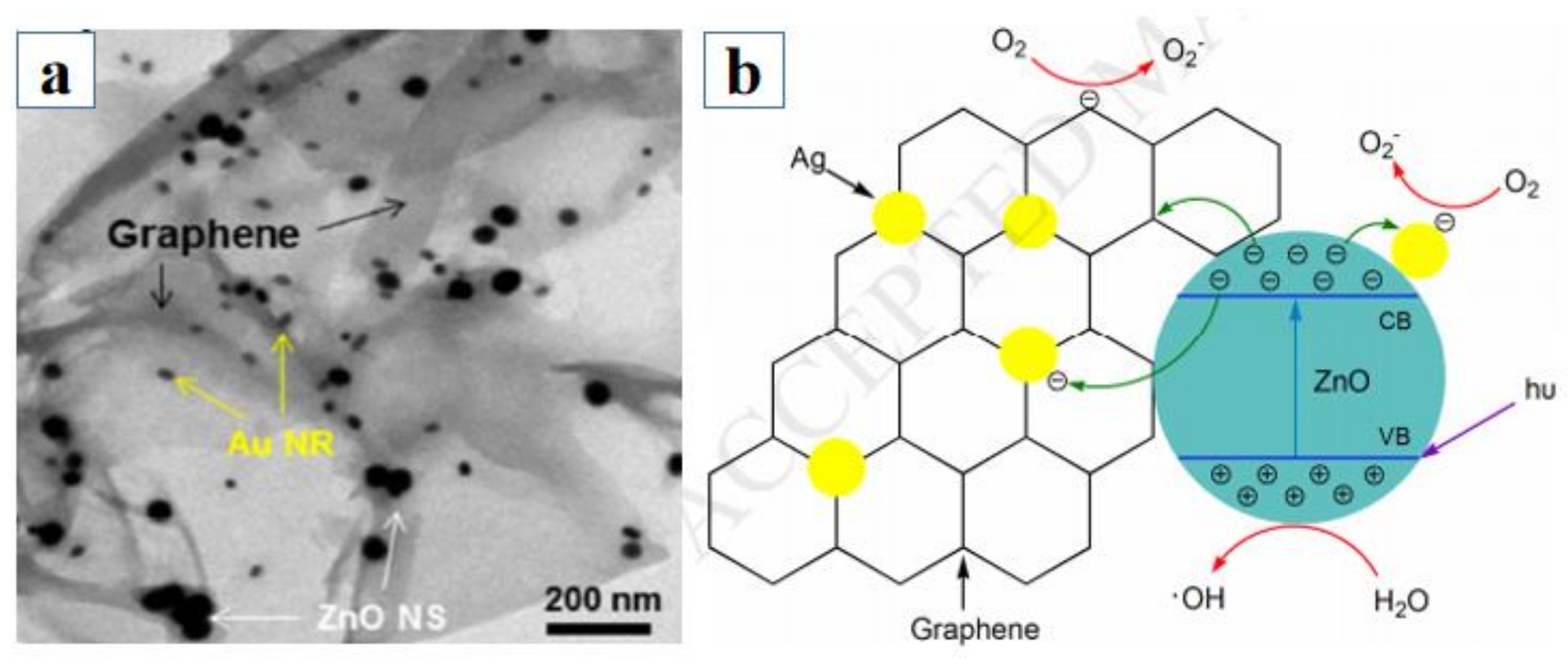
| ZnO nanoparticles–Au nanorods–2D graphene | 45.3 ± 3.7 nm (simple one-pot hydrothermal method) | 0.5 mg·mL−1 graphene | 4 mg.mL−1 in methanol | 5 mM 50 mL nitrobenzene (NB) in methanol solution | 500 W UV−Vis lamp with the wavelength above 420 nm | Achieved 97.8% efficiency with 18 mM ZnO and 0.5 mM Au | [45] |
| ZnO nanorods –CdS–2D graphene | 95 degree refluxing method | 5 wt% graphene | 10 mg with 40 mg HCOONH 4 (hole scavenger) | 40 mL 10 mg·L−1 aromatic nitro compounds solution | 300 W Xe arc lamp with wavelength less than 420 nm | 95% efficiency (16 min illumination) | [19] |
| Ag nanoparticles–ZnO nanorods–2D graphene | Low-temperature microwave-assisted solution method | 1 wt% graphene oxide | 50 mg | 50 mL 20 mg·L−1 MO solution | 300 W 365 nm-wavelength Hg lamp | 94.8% efficiency for the first text, 91.7% efficiency for the fifth text (80 min illumination for each test) | [46] |
| ZnO–2D graphene hollow microspheres with Au nanoparticles | Individual ZnO nanoparticles: 50 nm; microspheres: 1.6 um | The atomic contents of Au and C were 9% and 13.3% | \ | 10 mL 10 μM MB solution | 20 W black-light (UVA) lamps (wavelength range 315−400 nm) | 68% efficiency | [40] |
| ZnO nanoparticles–Pt (Pd) nanoparticles–2D graphene | One-pot hydrothermal method | 50 mg graphene oxide | \ | 1.0 M methanol solution | 0.3 mW.cm−2 UV light with wavelength of 250–270 nm and visible light with wavelength over 420 nm | \ | [47] |
| Nitrogen doped ZnO nanoparticles–2D graphene | 4–9 nm (facile wet chemical method) | 0.3% graphene | 0.2 mg | 200 mL 0.25 M aqueous KOH bubbled by hydrogen sulfide (H2S) for about 1 h at the rate of 2.5 mL min−1 at 299 K | 300 W visible light | Hydrogen evolution rate of 5072 µmol·h−1 | [48] |
| ZnO nanorods–3D graphene | 100 nm (hydrothermal method) | \ | 0.2 mg.mL−1 | 25 mL 5 ppm RhB solution | 100 mW·cm−2 simulated solar light | Over 95% efficiency in 150 min illumination | [53] |
| Cl-doped ZnO nanowires grown on 3D graphene | 40–100 nm (hydrothermal method) | 2 cm × 2 cm | 50 mL 5mg·L−1 RhB solution | A 150 W xenon lamp for UV irradiation | Finished within 75 min | [51] | |
| ZnO nanorods–3D graphene | 500 nm (hydrothermal method) | \ | 6 mg.mL−1 | 20 mL 5 mmol·L−1 MO solution | 300 W UV light with wavelength of 365 nm | 92% efficiency in 180 min illumination | [52] |
| Structure | Synthesis Method | Detection Light | Bias | Dark Current or Conductance | Photo Current or Conductance | Photocurrent and Dark Current Ratio | Response Time | Recovery Time | Photovoltaic Responsivity | Photoconductive Gain | External Quantum Efficiency (EQE) | Ref |
|---|---|---|---|---|---|---|---|---|---|---|---|---|
| ZnO nanorods with GQDs | Hydrothermal method | 80 mW·cm−2 white light | −1 V | 0.89 mA·cm−2 | 13.42 mA·cm−2 | 15 | \ | \ | 36 A/W under illumination with 340 nm wavelength | \ | 13.161% under illumination with 340 nm wavelength | [37] |
| ZnO nanorods– GQDs | Methanol-assisted hydrothermal method (ZnO), high pressure microwave irradiation of citric acid and ethanolamine (GQDs) | 365 nm, 10 uW UV light | 1 V | 2.24 mA·cm−2 | 320.3 mA·cm−2 | 142.99 | 2.14 s at 2 V bias | 2.14 s at 2 V bias | 6.62 × 10⁴ A/W under 2 V bias | \ | \ | [39] |
| ZnO nanowires on graphene sheet | Hydrothermal method | 370 nm, 0.215 uW UV light | 1 V | 1.53 nA | 3.4 × 10⁻⁵ A | 2.2 × 10 4 | \ | \ | \ | \ | \ | [43] |
| ZnO nanowires on graphene sheet | Hydrothermal method + electrophoretic deposition | Solid state lasers with wavelengths of 532, 808, and 1064 nm | \ | Saturated current calculated = 2.25 × 10⁻⁴ A | \ | \ | 0.1 s for 138 mW laser with wavelength of 532 nm | 0.1 s for 138 mW laser with wavelength of 532 nm | 0.55, 0.33 and 0.20 mV/W for the 1064, 532, and 808 nm lasers | \ | \ | [62] |
| ZnO nanowires on graphene sheet | Resistive thermal evaporation | 365 nm, 1.3 mW·cm−2 UV light | −5 V | \ | \ | \ | 3 s | 0.47s | 23 A·W−1. | \ | 7845.54% | [44] |
| ZnO nanorods on graphene sheet | CVD vapor-solid method | 365 nm, 10 mW·cm−2 UV light | 0 V | 0.3 uA | 0.15 uA | 5 | 0.1 s | 0.2 s | \ | \ | \ | [2] |
| ZnO nanorods on graphene sheet | Magnetron sputtering (ZnO), chemical vapor deposition (graphene sheet), PMMA-assisted method (transference of graphene sheet) | 325 nm, 2.93–21.26 uW·cm−2 UV light | −1V | 4 × 10⁻⁶ A with bias of −2 V | \ | \ | 0.3 s | 0.5 s | \ | \ | \ | [60] |
| ZnO quantum dots on graphene sheet | Printing method | 340 nm, 15 uW·cm−2 UV light | 10 V | \ | \ | 1.7 | 5 s | 85.1 | 9.9 × 10⁸ A/W | 3.6 × 10⁹ | \ | [58] |
| ZnO nanoparticles–graphene nanodots | PS NSa-assisted spin-coating method | 300 nm | 5 V | 4.7904 × 10⁻⁹ A | 4.33 × 10⁻⁸ A | 9.04 | 2.5 s under 1 V bias and UV light with wavelength of 360 nm | 11 s under 1 V bias and UV light with wavelength of 360 nm | 22.55 mA/W | \ | 9.32% | [61] |
| ZnO nanowires on ZnO seeded graphene sheet | Floating hydrothermal method | 340 nm, 9.89 ± 1.56 uW UV light | 5 V | \ | 6.512 mA | \ | \ | \ | 728 A·W−1. | 2655 | \ | [59] |
| ZnO nanowires on 3D graphene foam | Vapor-solid evaporation | 365 nm, 1.3 mW·cm−2 UV light | 5 V | 50.5 uS with zero bias | 80.5 uS with zero bias | \ | 9.5 s | 38s | \ | \ | 2490.8% under 8 V bias | [50] |
Publisher’s Note: MDPI stays neutral with regard to jurisdictional claims in published maps and institutional affiliations. |
© 2021 by the authors. Licensee MDPI, Basel, Switzerland. This article is an open access article distributed under the terms and conditions of the Creative Commons Attribution (CC BY) license (https://creativecommons.org/licenses/by/4.0/).
Share and Cite
Gao, C.; Zhong, K.; Fang, X.; Fang, D.; Zhao, H.; Wang, D.; Li, B.; Zhai, Y.; Chu, X.; Li, J.; et al. Brief Review of Photocatalysis and Photoresponse Properties of ZnO–Graphene Nanocomposites. Energies 2021, 14, 6403. https://doi.org/10.3390/en14196403
Gao C, Zhong K, Fang X, Fang D, Zhao H, Wang D, Li B, Zhai Y, Chu X, Li J, et al. Brief Review of Photocatalysis and Photoresponse Properties of ZnO–Graphene Nanocomposites. Energies. 2021; 14(19):6403. https://doi.org/10.3390/en14196403
Chicago/Turabian StyleGao, Chenhao, Keyi Zhong, Xuan Fang, Dan Fang, Hongbin Zhao, Dengkui Wang, Bobo Li, Yingjiao Zhai, Xueying Chu, Jinhua Li, and et al. 2021. "Brief Review of Photocatalysis and Photoresponse Properties of ZnO–Graphene Nanocomposites" Energies 14, no. 19: 6403. https://doi.org/10.3390/en14196403