
Methane Cracking for Hydrogen Production: A Review of Catalytic and Molten Media Pyrolysis


Abstract
:1. Introduction
2. Conventional Catalytic Methane Pyrolysis
2.1. Solid Metallic Catalysts
2.1.1. Role of Metal Catalyst Supports
2.1.2. Role of Metal Catalyst Promoters
2.1.3. Metal Catalysts Deactivation
2.1.4. Metal Catalysts Regeneration
2.2. Carbonaceous Catalysts
2.2.1. Role of Carbon Structure and Composition
2.2.2. Carbon Deactivation
2.2.3. Carbon Regeneration
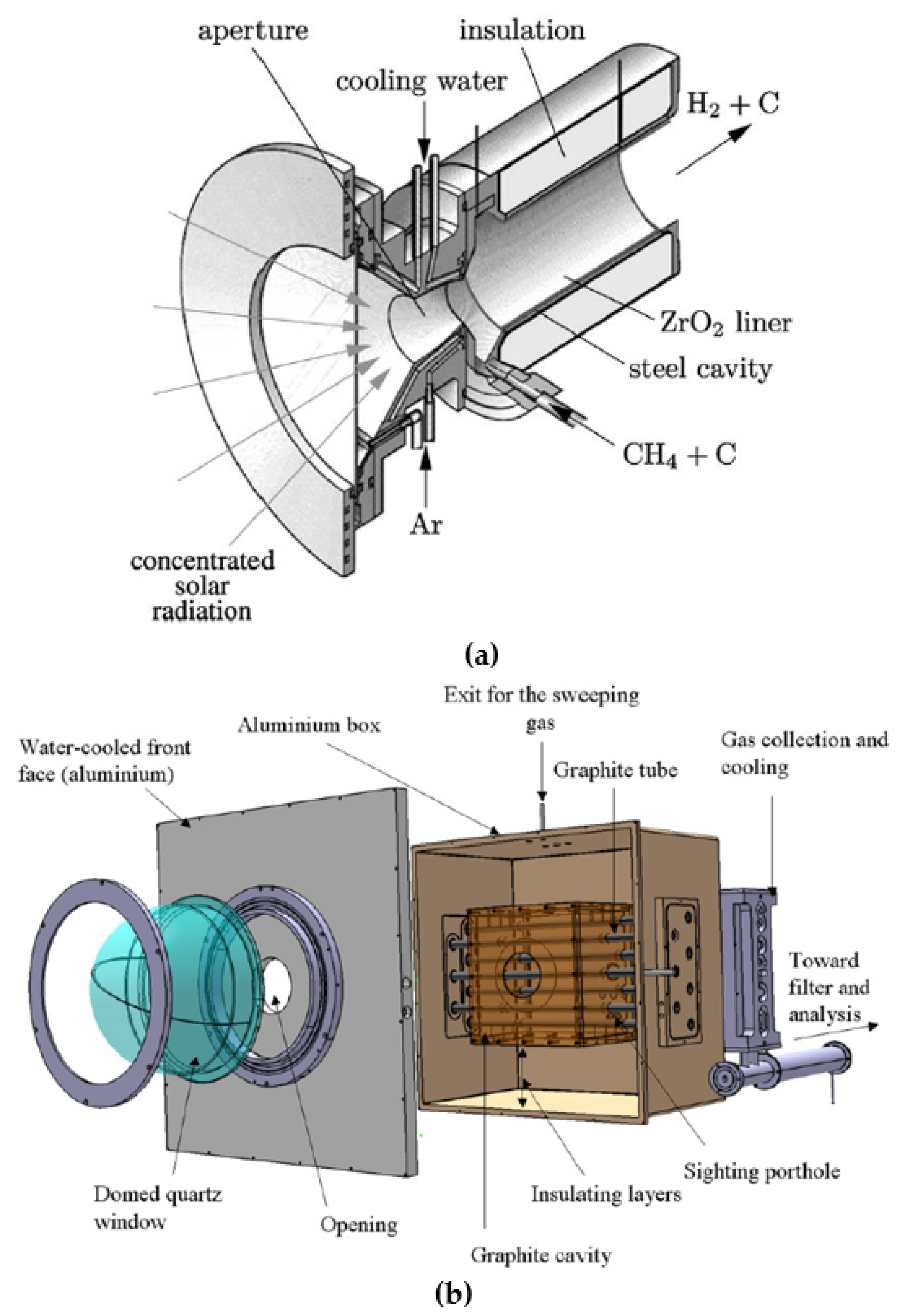
2.3. Solar Methane Pyrolysis
2.3.1. Advantages and Perspectives
2.3.2. Direct vs. Indirect Heating
2.3.3. Carbon Co-Feed
3. Methane Pyrolysis in Molten Media
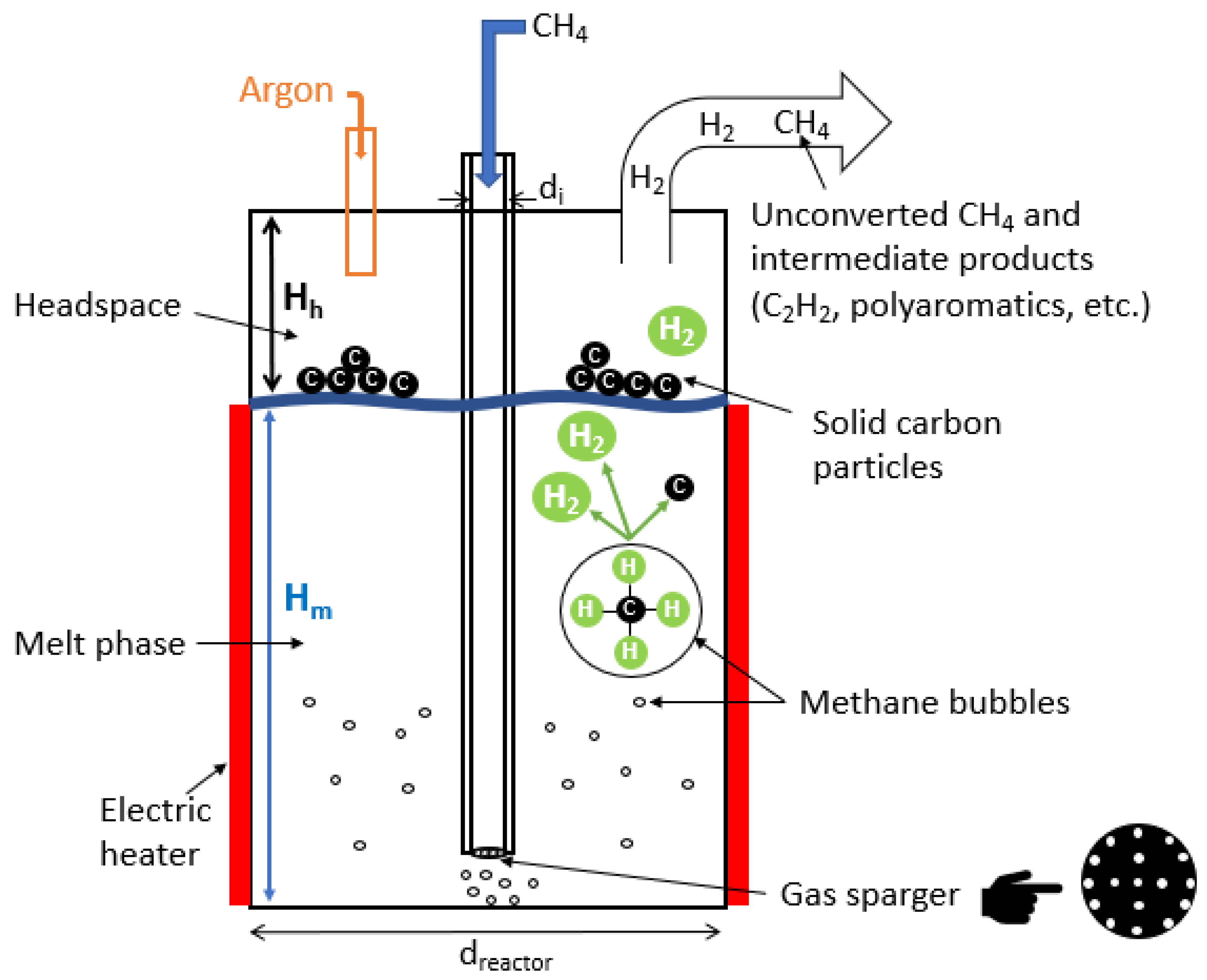
3.1. Concept and Principles
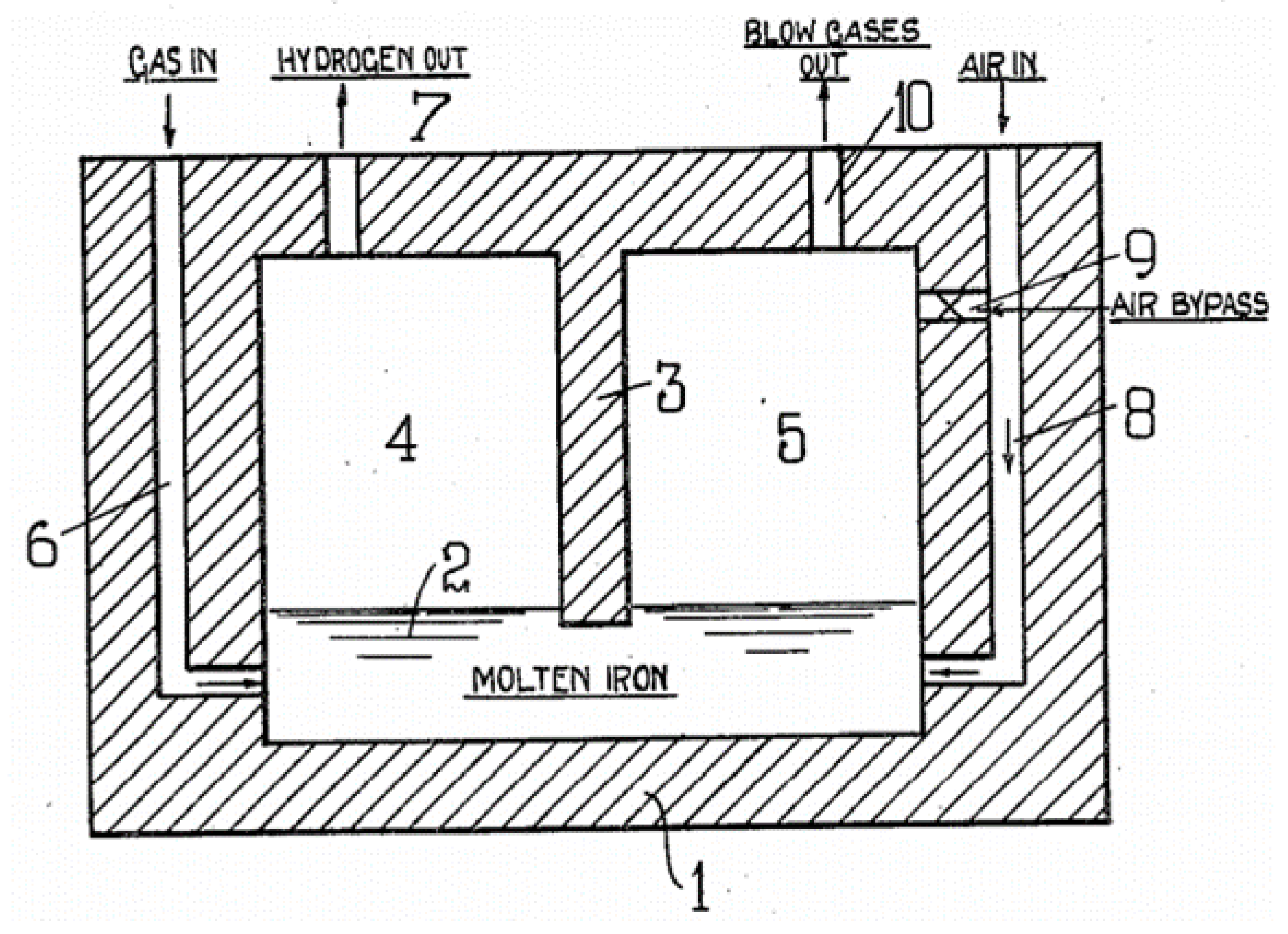
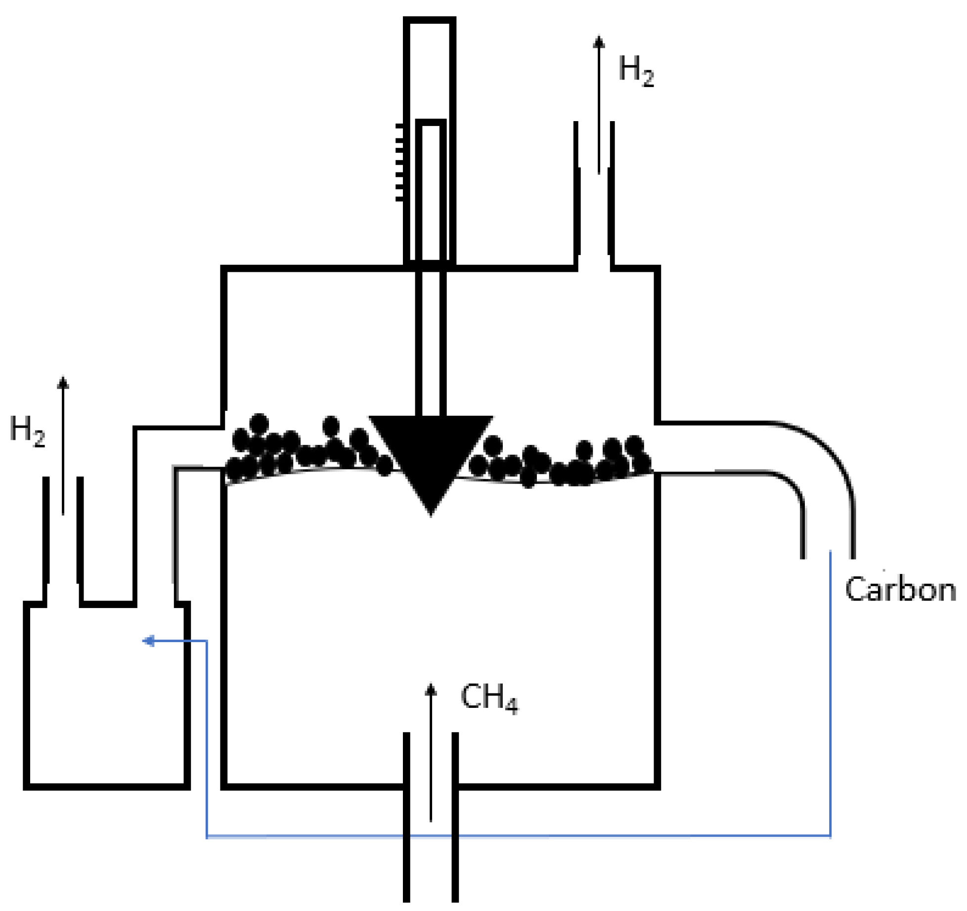
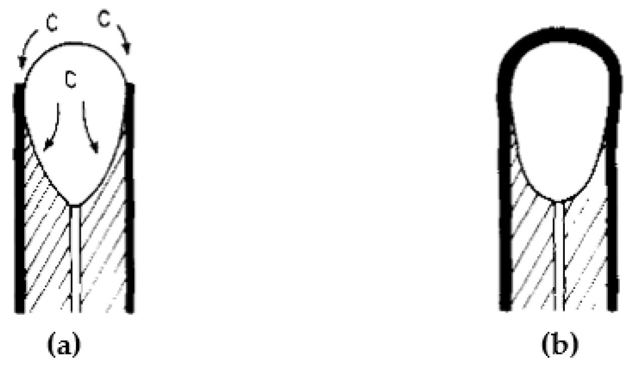
3.2. Reactor Design
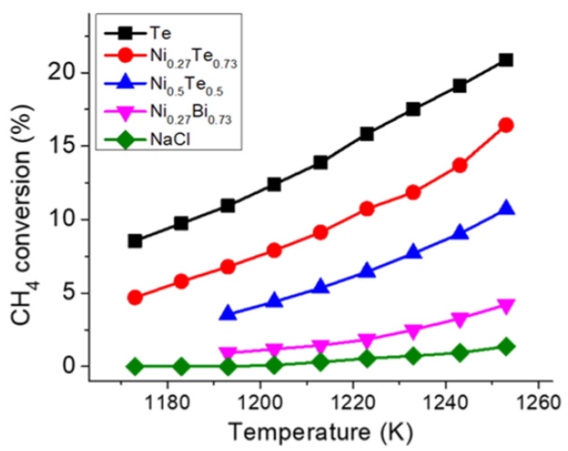
3.3. Molten Metals
3.4. Molten Salts
3.5. Comparison of Molten Metals and Molten Salts
3.6. Reaction Kinetics
4. Carbon Product Market and Characteristics
4.1. Solid Metal-Catalyzed Pyrolysis
4.2. Carbon-Catalyzed Pyrolysis
4.3. Pyrolysis in Molten Media
5. Parameters Affecting Methane Conversion
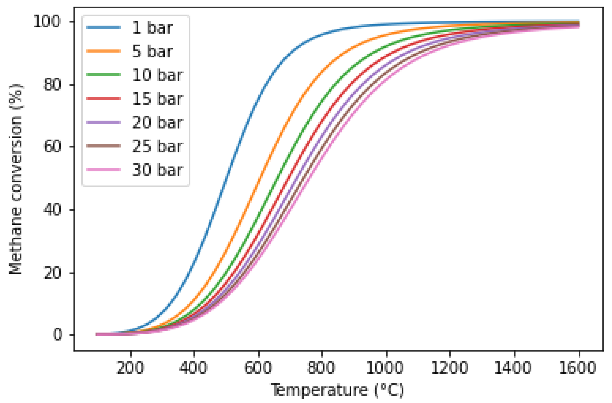
5.1. Temperature and Pressure
5.2. Feed Flow Rate
5.3. Bubble Size (Molten Media)
5.4. Reactor Material
5.5. Dilution Effect
6. Conclusions and Perspectives
Author Contributions
Funding
Institutional Review Board Statement
Informed Consent Statement
Data Availability Statement
Conflicts of Interest
References
- Kothari, R.; Buddhi, D.; Sawhney, R.L. Comparison of environmental and economic aspects of various hydrogen production methods. Renew. Sustain. Energy Rev. 2008, 12, 553–563. [Google Scholar] [CrossRef]
- Holladay, J.D.; Hu, J.; King, D.L.; Wang, Y. An overview of hydrogen production technologies. Catal. Today 2009, 139, 244–260. [Google Scholar] [CrossRef]
- Plevan, M.; Geißler, T.; Abánades, A.; Mehravaran, K.; Rathnam, R.K.; Rubbia, C.; Salmieri, D.; Stoppel, L.; Stückrad, S.; Wetzel, T. Thermal cracking of methane in a liquid metal bubble column reactor: Experiments and kinetic analysis. Int. J. Hydrog. Energy 2015, 40, 8020–8033. [Google Scholar] [CrossRef]
- Abánades, A. The challenge of Hydrogen production for the transition to a CO2-free economy. Agron. Res. 2012, 10, 11–16. [Google Scholar]
- Abánades, A.; Ruiz, E.; Ferruelo, E.M.; Hernández, F.; Cabanillas, A.; Martínez-Val, J.M.; Rubio, J.A.; López, C.; Gavela, R.; Barrera, G.; et al. Experimental analysis of direct thermal methane cracking. Int. J. Hydrog. Energy 2011, 36, 12877–12886. [Google Scholar] [CrossRef] [Green Version]
- Nazir, H.; Louis, C.; Jose, S.; Prakash, J.; Muthuswamy, N.; Buan, M.E.M.; Flox, C.; Chavan, S.; Shi, X.; Kauranen, P.; et al. Is the H2 economy realizable in the foreseeable future? Part I: H2 production methods. Int. J. Hydrog. Energy 2020, 45, 13777–13788. [Google Scholar] [CrossRef]
- Lemus, R.G.; Martínez Duart, J.M. Updated hydrogen production costs and parities for conventional and renewable technologies. Int. J. Hydrog. Energy 2010, 35, 3929–3936. [Google Scholar] [CrossRef]
- Weger, L.; Abánades, A.; Butler, T. Methane cracking as a bridge technology to the hydrogen economy. Int. J. Hydrog. Energy 2017, 42, 720–731. [Google Scholar] [CrossRef] [Green Version]
- Utrilla, R.; Pinilla, J.L.; Suelves, I.; Lázaro, M.J.; Moliner, R. Catalytic decomposition of methane for the simultaneous co-production of CO2-free hydrogen and carbon nanofibre based polymers. Fuel 2011, 90, 430–432. [Google Scholar] [CrossRef]
- Dagle, R.A.; Dagle, V.; Bearden, M.D.; Holladay, J.D.; Krause, T.R.; Ahmed, S. An Overview of Natural Gas Conversion Technologies for Co-Production of Hydrogen and Value-Added Solid Carbon Products; Pacific Northwest National Lab: Richland, WA, USA, 2017.
- Muradov, N.; Smith, F.; Huang, C.; T-Raissi, A. Autothermal catalytic pyrolysis of methane as a new route to hydrogen production with reduced CO2 emissions. Catal. Today 2006, 116, 281–288. [Google Scholar] [CrossRef]
- Rodat, S.; Abanades, S.; Coulié, J.; Flamant, G. Kinetic modelling of methane decomposition in a tubular solar reactor. Chem. Eng. J. 2009, 146, 120–127. [Google Scholar] [CrossRef]
- Keipi, T.; Tolvanen, K.E.S.; Tolvanen, H.; Konttinen, J. Thermo-catalytic decomposition of methane: The effect of reaction parameters on process design and the utilization possibilities of the produced carbon. Energy Convers. Manag. 2016, 126, 923–934. [Google Scholar] [CrossRef]
- Abanades, S.; Flamant, G. Experimental study and modeling of a high-temperature solar chemical reactor for hydrogen production from methane cracking. Int. J. Hydrog. Energy 2007, 32, 1508–1515. [Google Scholar] [CrossRef]
- Sajid, M.U.; Bicer, Y. Thermodynamic assessment of chemical looping combustion and solar thermal methane cracking-based integrated system for green ammonia production. Therm. Sci. Eng. Prog. 2020, 19, 100588. [Google Scholar] [CrossRef]
- Gonzalez-Aguilar, J.; Dème, I.; Fulcheri, L.; Flamant, G.; Gruenberger, T.M.; Ravary, B. Comparison of simple particle-radiation coupling models applied on a plasma black process. Plasma Chem. Plasma Process. 2004, 24, 603–623. [Google Scholar] [CrossRef]
- Holmen, A.; Olsvik, O.; Rokstad, O.A. Pyrolysis of natural gas: Chemistry and process concepts. Fuel Process. Technol. 1995, 42, 249–267. [Google Scholar] [CrossRef]
- Abánades, A.; Rubbia, C.; Salmieri, D. Technological challenges for industrial development of hydrogen production based on methane cracking. Energy 2012, 46, 359–363. [Google Scholar] [CrossRef]
- Ashik, U.P.M.; Wan Daud, W.M.A.; Abbas, H.F. Production of greenhouse gas free hydrogen by thermocatalytic decomposition of methane—A review. Renew. Sustain. Energy Rev. 2015, 44, 221–256. [Google Scholar] [CrossRef] [Green Version]
- Pudukudy, M.; Yaakob, Z.; Jia, Q.; Sobri Takriff, M. Catalytic decomposition of undiluted methane into hydrogen and carbon nanotubes over Pt promoted Ni/CeO2 catalysts. New J. Chem. 2018, 42, 14843–14856. [Google Scholar] [CrossRef]
- Kopp, M.; Coleman, D.; Stiller, C.; Scheffer, K.; Aichinger, J.; Scheppat, B. Energiepark Mainz: Technical and economic analysis of the worldwide largest Power-to-Gas plant with PEM electrolysis. Int. J. Hydrog. Energy 2017, 42, 13311–13320. [Google Scholar] [CrossRef]
- Ayillath Kutteri, D.; Wang, I.W.; Samanta, A.; Li, L.; Hu, J. Methane decomposition to tip and base grown carbon nanotubes and COx-free H2 over mono- and bimetallic 3d transition metal catalysts. Catal. Sci. Technol. 2018, 8, 858–869. [Google Scholar] [CrossRef]
- Dunker, A.M.; Kumar, S.; Mulawa, P.A. Production of hydrogen by thermal decomposition of methane in a fluidized-bed reactor—Effects of catalyst, temperature, and residence time. Int. J. Hydrog. Energy 2006, 31, 473–484. [Google Scholar] [CrossRef]
- Patel, S.; Kundu, S.; Halder, P.; Marzbali, M.H.; Chiang, K.; Surapaneni, A.; Shah, K. Production of hydrogen by catalytic methane decomposition using biochar and activated char produced from biosolids pyrolysis. Int. J. Hydrog. Energy 2020, 45, 29978–29992. [Google Scholar] [CrossRef]
- Abbas, H.F.; Daud, W.M.A.W. Influence of reactor material and activated carbon on the thermocatalytic decomposition of methane for hydrogen production. Appl. Catal. A Gen. 2010, 388, 232–239. [Google Scholar] [CrossRef]
- Botas, J.A.; Serrano, D.P.; Guil-López, R.; Pizarro, P.; Gómez, G. Methane catalytic decomposition over ordered mesoporous carbons: A promising route for hydrogen production. Int. J. Hydrog. Energy 2010, 35, 9788–9794. [Google Scholar] [CrossRef]
- Bai, Z.; Chen, H.; Li, W.; Li, B. Hydrogen production by methane decomposition over coal char. Int. J. Hydrog. Energy 2006, 31, 899–905. [Google Scholar] [CrossRef]
- Abánades, A.; Rubbia, C.; Salmieri, D. Thermal cracking of methane into Hydrogen for a CO2-free utilization of natural gas. Int. J. Hydrog. Energy 2013, 38, 8491–8496. [Google Scholar] [CrossRef]
- Tyrer, D. Production of Hydrogen. U.S. Patent 1,803,221, 28 April 1931. [Google Scholar]
- Steinberg, M. Fossil fuel decarbonization technology for mitigating global warming. Int. J. Hydrog. Energy 1999, 24, 771–777. [Google Scholar] [CrossRef] [Green Version]
- Schultz, I.; Agar, D.W. Decarbonisation of fossil energy via methane pyrolysis using two reactor concepts: Fluid wall flow reactor and molten metal capillary reactor. Int. J. Hydrog. Energy 2015, 40, 11422–11427. [Google Scholar] [CrossRef]
- Kudinov, I.V.; Pimenov, A.A.; Kryukov, Y.A.; Mikheeva, G.V. A theoretical and experimental study on hydrodynamics, heat exchange and diffusion during methane pyrolysis in a layer of molten tin. Int. J. Hydrog. Energy 2021. [Google Scholar] [CrossRef]
- Palmer, C.; Tarazkar, M.; Kristoffersen, H.H.; Gelinas, J.; Gordon, M.J.; McFarland, E.W.; Metiu, H. Methane Pyrolysis with a Molten Cu-Bi Alloy Catalyst. ACS Catal. 2019, 9, 8337–8345. [Google Scholar] [CrossRef]
- Sánchez-Bastardo, N.; Schlögl, R.; Ruland, H. Methane Pyrolysis for CO2-Free H2 Production: A Green Process to Overcome Renewable Energies Unsteadiness. Chem. Ing. Tech. 2020, 92, 1596–1609. [Google Scholar] [CrossRef]
- Amin, A.M.; Croiset, E.; Epling, W. Review of methane catalytic cracking for hydrogen production. Int. J. Hydrog. Energy 2011, 36, 2904–2935. [Google Scholar] [CrossRef]
- Schneider, S.; Bajohr, S.; Graf, F.; Kolb, T. State of the Art of Hydrogen Production via Pyrolysis of Natural Gas. ChemBioEng Rev. 2020, 92, 1023–1032. [Google Scholar] [CrossRef]
- Muradov, N.; Veziroglu, T. “Green” path from fossil-based to hydrogen economy: An overview of carbon-neutral technologies. Int. J. Hydrog. Energy 2008, 33, 6804–6839. [Google Scholar] [CrossRef]
- Abbas, H.F.; Wan Daud, W.M.A. Hydrogen production by methane decomposition: A review. Int. J. Hydrog. Energy 2010, 35, 1160–1190. [Google Scholar] [CrossRef]
- Samanta, S.K.; Verma, P. Advanced Hydrogen Production through Methane Cracking: A Review. Sci. Technol. 2015, 1, 109–123. [Google Scholar]
- Chen, L.; Qi, Z.; Zhang, S.; Su, J.; Somorjai, G.A. Catalytic Hydrogen Production from Methane: A Review on Recent Progress and Prospect. Catalysts 2020, 10, 858. [Google Scholar] [CrossRef]
- Takenaka, S.; Shigeta, Y.; Tanabe, E.; Otsuka, K. Methane decomposition into hydrogen and carbon nanofibers over supported Pd-Ni catalysts. J. Catal. 2003, 220, 468–477. [Google Scholar] [CrossRef]
- Zhou, L.; Basset, J.M. Unsupported NiPt alloy metal catalysts prepared by water-in-oil (W/O) microemulsion method for methane cracking. Fuel 2016, 181, 805–810. [Google Scholar] [CrossRef]
- Mei, I.L.S.; Lock, S.S.M.; Vo, D.V.N.; Abdullah, B. Thermo-catalytic methane decomposition for hydrogen production: Effect of palladium promoter on Ni-based catalysts. Bull. Chem. React. Eng. Catal. 2016, 11, 191–199. [Google Scholar] [CrossRef] [Green Version]
- Ouyang, M.; Boldrin, P.; Maher, R.C.; Chen, X.; Liu, X.; Cohen, L.F.; Brandon, N.P. A mechanistic study of the interactions between methane and nickel supported on doped ceria. Appl. Catal. B Environ. 2019, 248, 332–340. [Google Scholar] [CrossRef]
- Chen, J.; Li, Y.; Li, Z.; Zhang, X. Production of COx-free hydrogen and nanocarbon by direct decomposition of undiluted methane on Ni-Cu-alumina catalysts. Appl. Catal. A Gen. 2004, 269, 179–186. [Google Scholar] [CrossRef]
- Ermakova, M.A.; Ermakov, D.Y.; Kuvshinov, G.G. Effective catalysts for direct cracking of methane to produce hydrogen and filamentous carbon. Part I. Nickel catalysts. Appl. Catal. A Gen. 2000, 201, 61–70. [Google Scholar] [CrossRef]
- Bayat, N.; Rezaei, M.; Meshkani, F. Methane decomposition over Ni-Fe/Al2O3 catalysts for production of COx-free hydrogen and carbon nanofiber. Int. J. Hydrog. Energy 2016, 41, 1574–1584. [Google Scholar] [CrossRef]
- Wang, D.; Zhang, J.; Sun, J.; Gao, W.; Cui, Y. Effect of metal additives on the catalytic performance of Ni/Al2O3 catalyst in thermocatalytic decomposition of methane. Int. J. Hydrog. Energy 2019, 44, 7205–7215. [Google Scholar] [CrossRef]
- Bayat, N.; Rezaei, M.; Meshkani, F. COx-free hydrogen and carbon nanofibers production by methane decomposition over nickel-alumina catalysts. Korean J. Chem. Eng. 2016, 33, 490–499. [Google Scholar] [CrossRef]
- Bayat, N.; Rezaei, M.; Meshkani, F. Methane dissociation to COx-free hydrogen and carbon nanofiber over Ni-Cu/Al2O3 catalysts. Fuel 2017, 195, 88–96. [Google Scholar] [CrossRef] [Green Version]
- Bayat, N.; Rezaei, M.; Meshkani, F. Hydrogen and carbon nanofibers synthesis by methane decomposition over Ni-Pd/Al2O3 catalyst. Int. J. Hydrog. Energy 2016, 41, 5494–5503. [Google Scholar] [CrossRef]
- Rastegarpanah, A.; Rezaei, M.; Meshkani, F.; Zhang, K.; Zhao, X.; Pei, W.; Liu, Y.; Deng, J.; Arandiyan, H.; Dai, H. Mesoporous Ni/MeOx (Me = Al, Mg, Ti, and Si): Highly efficient catalysts in the decomposition of methane for hydrogen production. Appl. Surf. Sci. 2019, 478, 581–593. [Google Scholar] [CrossRef]
- Hasnan, N.S.N.; Timmiati, S.N.; Lim, K.L.; Yaakob, Z.; Kamaruddin, N.H.N.; Teh, L.P. Recent developments in methane decomposition over heterogeneous catalysts: An overview. Mater. Renew. Sustain. Energy 2020, 9, 1–18. [Google Scholar] [CrossRef] [Green Version]
- Al-Fatesh, A.S.; Fakeeha, A.H.; Ibrahim, A.A.; Khan, W.U.; Atia, H.; Eckelt, R.; Seshan, K.; Chowdhury, B. Decomposition of methane over alumina supported Fe and Ni–Fe bimetallic catalyst: Effect of preparation procedure and calcination temperature. J. Saudi Chem. Soc. 2018, 22, 239–247. [Google Scholar] [CrossRef] [Green Version]
- Berndt, F.M.; Perez-Lopez, O.W. Catalytic decomposition of methane over Ni/SiO2: Influence of Cu addition. React. Kinet. Mech. Catal. 2017, 120, 181–193. [Google Scholar] [CrossRef]
- Li, J.; Zhao, L.; He, J.; Dong, L.; Xiong, L.; Du, Y.; Yang, Y.; Wang, H.; Peng, S. Methane decomposition over high-loaded Ni-Cu-SiO2 catalysts. Fusion Eng. Des. 2016, 113, 279–287. [Google Scholar] [CrossRef]
- Echegoyen, Y.; Suelves, I.; Lázaro, M.J.; Moliner, R.; Palacios, J.M. Hydrogen production by thermocatalytic decomposition of methane over Ni-Al and Ni-Cu-Al catalysts: Effect of calcination temperature. J. Power Sources 2007, 169, 150–157. [Google Scholar] [CrossRef]
- Zhou, L.; Enakonda, L.R.; Saih, Y.; Loptain, S.; Gary, D.; Del-Gallo, P.; Basset, J.M. Catalytic Methane Decomposition over Fe-Al2O3. ChemSusChem 2016, 9, 1243–1248. [Google Scholar] [CrossRef] [PubMed]
- Wang, J.; Jin, L.; Li, Y.; Hu, H. Preparation of fe-doped carbon catalyst for methane decomposition to hydrogen. Ind. Eng. Chem. Res. 2017, 56, 11021–11027. [Google Scholar] [CrossRef]
- Pudukudy, M.; Yaakob, Z.; Mazuki, M.Z.; Takriff, M.S.; Jahaya, S.S. One-pot sol-gel synthesis of MgO nanoparticles supported nickel and iron catalysts for undiluted methane decomposition into COx free hydrogen and nanocarbon. Appl. Catal. B Environ. 2017, 218, 298–316. [Google Scholar] [CrossRef]
- Zhang, T.; Amiridis, M.D. Hydrogen production via the direct cracking of methane over silica-supported nickel catalysts. Appl. Catal. A Gen. 1998, 167, 161–172. [Google Scholar] [CrossRef]
- Amin, A.M.; Croiset, E.; Constantinou, C.; Epling, W. Methane cracking using Ni supported on porous and non-porous alumina catalysts. Int. J. Hydrog. Energy 2012, 37, 9038–9048. [Google Scholar] [CrossRef]
- Venugopal, A.; Naveen Kumar, S.; Ashok, J.; Hari Prasad, D.; Durga Kumari, V.; Prasad, K.; Subrahmanyam, M. Hydrogen production by catalytic decomposition of methane over Ni/SiO2. Int. J. Hydrog. Energy 2007, 32, 1782–1788. [Google Scholar] [CrossRef]
- Gac, W.; Denis, A.; Borowiecki, T.; Kępiński, L. Methane decomposition over Ni–MgO–Al2O3 catalysts. Appl. Catal. A Gen. 2009, 357, 236–243. [Google Scholar] [CrossRef]
- Ermakova, M.A.; Ermakov, D.Y. Ni/SiO2 and Fe/SiO2 catalysts for production of hydrogen and filamentous carbon via methane decomposition. Catal. Today 2002, 77, 225–235. [Google Scholar] [CrossRef]
- Li, Y.; Chen, J.; Chang, L. Catalytic growth of carbon fibers from methane on a nickel-alumina composite catalyst prepared from Feitknecht compound precursor. Appl. Catal. A Gen. 1997, 163, 45–57. [Google Scholar] [CrossRef]
- Figueiredo, J.L.; Órfão, J.J.M.; Cunha, A.F. Hydrogen production via methane decomposition on Raney-type catalysts. Int. J. Hydrog. Energy 2010, 35, 9795–9800. [Google Scholar] [CrossRef]
- Forzatti, P.; Lietti, L. Catalyst deactivation. Catal. today 1999, 52, 165–181. [Google Scholar] [CrossRef]
- Bartholomew, C.H. Mechanisms of catalyst deactivation. Chem. Eng. J. 2001, 212, 17–60. [Google Scholar] [CrossRef]
- Argyle, M.; Bartholomew, C. Heterogeneous Catalyst Deactivation and Regeneration: A Review. Catalysts 2015, 5, 145–269. [Google Scholar] [CrossRef] [Green Version]
- Baker, R.T.K.; Barber, M.A.; Harris, P.S.; Feates, F.S.; Waite, R.J. Nucleation and growth of carbon deposits from the nickel catalyzed decomposition of acetylene. Appl. Catal. A Gen. 1972, 26, 51–62. [Google Scholar] [CrossRef]
- Ginsburg, J.M.; Piña, J.; El Solh, T.; De Lasa, H.I. Coke formation over a nickel catalyst under methane dry reforming conditions: Thermodynamic and kinetic models. Ind. Eng. Chem. Res. 2005, 44, 4846–4854. [Google Scholar] [CrossRef]
- Wagman, D.D.; Kilpatrick, J.E.; Taylor, W.J.; Pitzer, K.S.; Rossini, F.D. Heats, free energies, and equilibrium constants of some reactions involving O2, H2, H2O, C, CO, CO2, and CH4. J. Res. Natl. Bur. Stand 1945, 34, 143. [Google Scholar] [CrossRef]
- Otsuka, K.; Takenaka, S.; Ohtsuki, H. Production of pure hydrogen by cyclic decomposition of methane and oxidative elimination of carbon nanofibers on supported-Ni-based catalysts. Appl. Catal. A Gen. 2004, 273, 113–124. [Google Scholar] [CrossRef]
- Rahman, M.S.; Croiset, E.; Hudgins, R.R. Catalytic decomposition of methane for hydrogen production. Top. Catal. 2006, 37, 137–145. [Google Scholar] [CrossRef]
- Villacampa, J.I.; Royo, C.; Romeo, E.; Montoya, J.A.; Del Angel, P.; Monzón, A. Catalytic decomposition of methane over Ni-Al2O3 coprecipitated catalysts Reaction and regeneration studies. Appl. Catal. A Gen. 2003, 252, 363–383. [Google Scholar] [CrossRef]
- Koç, R.; Alper, E.; Croiset, E.; Elkamel, A. Partial regeneration of Ni-based catalysts for hydrogen production via methane cracking. Turkish J. Chem. 2008, 32, 157–168. [Google Scholar]
- Aiello, R.; Fiscus, J.E.; Zur Loye, H.C.; Amiridis, M.D. Hydrogen production via the direct cracking of methane over Ni/SiO2: Catalyst deactivation and regeneration. Appl. Catal. A Gen. 2000, 192, 227–234. [Google Scholar] [CrossRef]
- Suelves, I.; Lázaro, M.J.; Moliner, R.; Pinilla, J.L.; Cubero, H. Hydrogen production by methane decarbonization: Carbonaceous catalysts. Int. J. Hydrog. Energy 2007, 32, 3320–3326. [Google Scholar] [CrossRef]
- Muradov, N.; Smith, F.; T-Raissi, A. Catalytic activity of carbons for methane decomposition reaction. Catal. Today 2005, 102–103, 225–233. [Google Scholar] [CrossRef]
- Zhang, J.; Li, X.; Xie, W.; Hao, Q.; Chen, H.; Ma, X. K2CO3-promoted methane pyrolysis on nickel/coal-char hybrids. J. Anal. Appl. Pyrolysis 2018, 136, 53–61. [Google Scholar] [CrossRef]
- Pinilla, J.L.; Torres, D.; Lázaro, M.J.; Suelves, I.; Moliner, R.; Cañadas, I.; Rodríguez, J.; Vidal, A.; Martínez, D. Metallic and carbonaceous-based catalysts performance in the solar catalytic decomposition of methane for hydrogen and carbon production. Int. J. Hydrog. Energy 2012, 37, 9645–9655. [Google Scholar] [CrossRef]
- Strelko, V.; Malik, D.; Streat, M. Characterisation of the surface of oxidised carbon adsorbents. Carbon N. Y. 2002, 40, 95–104. [Google Scholar] [CrossRef]
- Serrano, D.P.; Botas, J.A.; Guil-Lopez, R. H2 production from methane pyrolysis over commercial carbon catalysts: Kinetic and deactivation study. Int. J. Hydrog. Energy 2009, 34, 4488–4494. [Google Scholar] [CrossRef]
- Jung, J.U.; Nam, W.; Yoon, K.J.; Han, G.Y. Hydrogen production by catalytic decomposition of methane over carbon catalysts in a fluidized bed. Korean J. Chem. Eng. 2007, 24, 674–678. [Google Scholar] [CrossRef]
- Lee, S.Y.; Ryu, B.H.; Han, G.Y.; Lee, T.J.; Yoon, K.J. Catalytic characteristics of specialty carbon blacks in decomposition of methane for hydrogen production. Carbon N. Y. 2008, 46, 1978–1986. [Google Scholar] [CrossRef]
- Kim, M.H.; Lee, E.K.; Jun, J.H.; Han, G.Y.; Kong, S.J.; Lee, B.K.; Lee, T.J.; Yoon, K.J. Hydrogen production by catalytic decomposition of methane over activated carbons: Deactivation study. Korean J. Chem. Eng. 2003, 20, 835–839. [Google Scholar] [CrossRef]
- Lázaro, M.J.; Pinilla, J.L.; Suelves, I.; Moliner, R. Study of the deactivation mechanism of carbon blacks used in methane decomposition. Int. J. Hydrog. Energy 2008, 33, 4104–4111. [Google Scholar] [CrossRef]
- Ashok, J.; Kumar, S.N.; Venugopal, A.; Kumari, V.D.; Tripathi, S.; Subrahmanyam, M. COx free hydrogen by methane decomposition over activated carbons. Catal. Commun. 2008, 9, 164–169. [Google Scholar] [CrossRef]
- Lee, K.K.; Han, G.Y.; Yoon, K.J.; Lee, B.K. Thermocatalytic hydrogen production from the methane in a fluidized bed with activated carbon catalyst. Catal. Today 2004, 93–95, 81–86. [Google Scholar] [CrossRef]
- Krzyzyński, S.; Kozłowski, M. Activated carbons as catalysts for hydrogen production via methane decomposition. Int. J. Hydrog. Energy 2008, 33, 6172–6177. [Google Scholar] [CrossRef]
- Abbas, H.F.; Daud, W.M.A.W. Thermocatalytic decomposition of methane for hydrogen production using activated carbon catalyst: Regeneration and characterization studies. Int. J. Hydrog. Energy 2009, 34, 8034–8045. [Google Scholar] [CrossRef]
- Sun, Z.Q.; Wu, J.H.; Haghighi, M.; Bromly, J.; Ng, E.; Wee, H.L.; Wang, Y.; Zhang, D.K. Methane cracking over a bituminous coal char. Energy Fuels 2007, 21, 1601–1605. [Google Scholar] [CrossRef]
- Yang, L.; Liu, F.; Liu, Y.; Quan, W.; He, J. Deep regeneration of activated carbon catalyst and autothermal analysis for chemical looping methane thermo-catalytic decomposition process. Int. J. Hydrog. Energy 2018, 43, 17633–17642. [Google Scholar] [CrossRef]
- Dahl, J.K.; Buechler, K.J.; Weimer, A.W.; Lewandowski, A.; Bingham, C. Solar-thermal dissociation of methane in a fluid-wall aerosol flow reactor. Int. J. Hydrog. Energy 2004, 29, 725–736. [Google Scholar] [CrossRef]
- Rodat, S.; Abanades, S.; Flamant, G. Co-production of hydrogen and carbon black from solar thermal methane splitting in a tubular reactor prototype. Sol. Energy 2011, 85, 645–652. [Google Scholar] [CrossRef]
- Kumar, L.; Hasanuzzaman, M.; Rahim, N.A. Global advancement of solar thermal energy technologies for industrial process heat and its future prospects: A review. Energy Convers. Manag. 2019, 195, 885–908. [Google Scholar] [CrossRef]
- Abanades, S.; Tescari, S.; Rodat, S.; Flamant, G. Natural gas pyrolysis in double-walled reactor tubes using thermal plasma or concentrated solar radiation as external heating source. J. Nat. Gas Chem. 2009, 18, 1–8. [Google Scholar] [CrossRef]
- Rodat, S.; Abanades, S.; Grivei, E.; Patrianakos, G.; Zygogianni, A.; Konstandopoulos, A.G.; Flamant, G. Characterisation of carbon blacks produced by solar thermal dissociation of methane. Carbon 2011, 49, 3084–3091. [Google Scholar] [CrossRef]
- Abanades, S.; Kimura, H.; Otsuka, H. Hydrogen production from CO2-free thermal decomposition of methane: Design and on-sun testing of a tube-type solar thermochemical reactor. Fuel Process. Technol. 2014, 122, 153–162. [Google Scholar] [CrossRef]
- Abanades, S.; Flamant, G. High-temperature solar chemical reactors for hydrogen production from natural gas cracking. Chem. Eng. Commun. 2008, 195, 1159–1175. [Google Scholar] [CrossRef]
- Rodat, S.; Abanades, S.; Sans, J.-L.; Flamant, G. A pilot-scale solar reactor for the production of hydrogen and carbon black from methane splitting. Int. J. Hydrog. Energy 2010, 35, 7748–7758. [Google Scholar] [CrossRef]
- Rodat, S.; Abanades, S.; Flamant, G. High-Temperature Solar Methane Dissociation in a Multitubular Cavity-Type Reactor in the Temperature Range 1823–2073 K. Energy Fuels 2009, 23, 2666–2674. [Google Scholar] [CrossRef]
- Rodat, S.; Abanades, S.; Sans, J.-L.; Flamant, G. Hydrogen production from solar thermal dissociation of natural gas: Development of a 10kW solar chemical reactor prototype. Sol. Energy 2009, 83, 1599–1610. [Google Scholar] [CrossRef]
- Rodat, S.; Abanades, S.; Flamant, G. Experimental evaluation of indirect heating tubular reactors for solar methane pyrolysis. Int. J. Chem. React. Eng. 2010, 8. [Google Scholar] [CrossRef]
- Yeheskel, J.; Epstein, M. Thermolysis of methane in a solar reactor for mass-production of hydrogen and carbon nano-materials. Carbon N. Y. 2011, 49, 4695–4703. [Google Scholar] [CrossRef]
- Kogan, M.; Kogan, A. Production of hydrogen and carbon by solar thermal methane splitting. I. The unseeded reactor. Int. J. Hydrog. Energy 2003, 28, 1187–1198. [Google Scholar] [CrossRef]
- Maag, G.; Zanganeh, G.; Steinfeld, A. Solar thermal cracking of methane in a particle-flow reactor for the co-production of hydrogen and carbon. Int. J. Hydrog. Energy 2009, 34, 7676–7685. [Google Scholar] [CrossRef]
- Paxman, D.; Trottier, S.; Nikoo, M.; Secanell, M.; Ordorica-Garcia, G. Initial experimental and theoretical investigation of solar molten media methane cracking for hydrogen production. Energy Procedia 2014, 49, 2027–2036. [Google Scholar] [CrossRef]
- Abanades, S.; Kimura, H.; Otsuka, H. A drop-tube particle-entrained flow solar reactor applied to thermal methane splitting for hydrogen production. Fuel 2015, 153, 56–66. [Google Scholar] [CrossRef]
- Abanades, S.; Kimura, H.; Otsuka, H. Kinetic investigation of carbon-catalyzed methane decomposition in a thermogravimetric solar reactor. Int. J. Hydrog. Energy 2015, 40, 10744–10755. [Google Scholar] [CrossRef]
- Abanades, S.; Flamant, G. Hydrogen production from solar thermal dissociation of methane in a high-temperature fluid-wall chemical reactor. Chem. Eng. Process. Process Intensif. 2008, 47, 490–498. [Google Scholar] [CrossRef]
- Abanades, S.; Kimura, H.; Otsuka, H. Hydrogen production from thermo-catalytic decomposition of methane using carbon black catalysts in an indirectly-irradiated tubular packed-bed solar reactor. Int. J. Hydrog. Energy 2014, 39, 18770–18783. [Google Scholar] [CrossRef]
- Diver, R.B. Receiver/Reactor Concepts for Thermochemical Transport of Solar Energy. J. Sol. Energy Eng. 1987, 109, 199–204. [Google Scholar] [CrossRef]
- Zsembinszki, G.; Solé, A.; Barreneche, C.; Prieto, C.; Fernández, A.; Cabeza, L. Review of Reactors with Potential Use in Thermochemical Energy Storage in Concentrated Solar Power Plants. Energies 2018, 11, 2358. [Google Scholar] [CrossRef] [Green Version]
- Koepf, E.; Alxneit, I.; Wieckert, C.; Meier, A. A review of high temperature solar driven reactor technology: 25 years of experience in research and development at the Paul Scherrer Institute. Appl. Energy 2017, 188, 620–651. [Google Scholar] [CrossRef]
- Alonso, E.; Romero, M. Review of experimental investigation on directly irradiated particles solar reactors. Renew. Sustain. Energy Rev. 2015, 41, 53–67. [Google Scholar] [CrossRef]
- Jafarian, M.; Abdollahi, M.R.; Nathan, G.J. Preliminary evaluation of a novel solar bubble receiver for heating a gas. Sol. Energy 2019, 182, 264–277. [Google Scholar] [CrossRef]
- Rodat, S.; Abanades, S.; Boujjat, H.; Chuayboon, S. On the path toward day and night continuous solar high temperature thermochemical processes: A review. Renew. Sustain. Energy Rev. 2020, 132. [Google Scholar] [CrossRef]
- Rodat, S.; Abanades, S. A Hybrid Windowless Dual Tube Solar Reactor for Continuous Volumetric Natural Gas Dissociation. Front. Energy Res. 2020, 8. [Google Scholar] [CrossRef]
- Rahimi, N.; Kang, D.; Gelinas, J.; Menon, A.; Gordon, M.J.; Metiu, H.; McFarland, E.W. Solid carbon production and recovery from high temperature methane pyrolysis in bubble columns containing molten metals and molten salts. Carbon N. Y. 2019, 151, 181–191. [Google Scholar] [CrossRef]
- Upham, D.C.; Agarwal, V.; Khechfe, A.; Snodgrass, Z.R.; Gordon, M.J.; Metiu, H.; McFarland, E.W. Catalytic molten metals for the direct conversion of methane to hydrogen and separable carbon. Science (80-) 2017, 358, 917–921. [Google Scholar] [CrossRef] [Green Version]
- Wang, K.; Li, W.S.; Zhou, X.P. Hydrogen generation by direct decomposition of hydrocarbons over molten magnesium. J. Mol. Catal. A Chem. 2008, 283, 153–157. [Google Scholar] [CrossRef]
- Rowe, S.C.; Ariko, T.A.; Weiler, K.M.; Spana, J.T.E.; Weimer, A.W. Reversible Molten Catalytic Methane Cracking Applied to Commercial Solar-Thermal Receivers. Energies 2020, 13, 6229. [Google Scholar] [CrossRef]
- Sakai, A.; Yamaguchi, F.; Kawazoe, T.; Yonemori, H.; Machida, Y. Process for Cracking Hydrocarbons Utilizing Amist of Molten Salt in the Reaction Zone. U.S. Patent 4,217,204, 12 August 1980. [Google Scholar]
- Tokuji, O. Method and Appartus for Thermal Cracking and Quenching. U.S. Patent 3,718,708, 27 February 1973. [Google Scholar]
- Dugan, J.; Israel, S.; PastrenaYao, K. Hydrocarbon Cracking in a Regenerable Molten Medium. U.S. Patent 3,876,527, 8 April 1975. [Google Scholar]
- Oblad, A.G.; Milliken, T.H.; Boedeker, E.R. Production of Hydrogen and Carbon. U.S. Patent 2,760,847, 28 August 1956. [Google Scholar]
- Leal Pérez, B.J.; Medrano Jiménez, J.A.; Bhardwaj, R.; Goetheer, E.; van Sint Annaland, M.; Gallucci, F. Methane pyrolysis in a molten gallium bubble column reactor for sustainable hydrogen production: Proof of concept & techno-economic assessment. Int. J. Hydrog. Energy 2020. [Google Scholar] [CrossRef]
- Zeng, J.; Tarazkar, M.; Pennebaker, T.; Gordon, M.J.; Metiu, H.; McFarland, E.W. Catalytic Methane Pyrolysis with Liquid and Vapor Phase Tellurium. ACS Catal. 2020, 10, 8223–8230. [Google Scholar] [CrossRef]
- Kang, D.; Palmer, C.; Mannini, D.; Rahimi, N.; Gordon, M.J.; Metiu, H.; McFarland, E.W. Catalytic Methane Pyrolysis in Molten Alkali Chloride Salts Containing Iron. ACS Catal. 2020, 10, 7032–7042. [Google Scholar] [CrossRef]
- Von Wald, G.A.; Masnadi, M.S.; Upham, D.C.; Brandt, A.R. Optimization-based technoeconomic analysis of molten-media methane pyrolysis for reducing industrial sector CO2 emissions. Sustain. Energy Fuels 2020, 4, 4598–4613. [Google Scholar] [CrossRef]
- Geißler, T.; Plevan, M.; Abánades, A.; Heinzel, A.; Mehravaran, K.; Rathnam, R.K.; Rubbia, C.; Salmieri, D.; Stoppel, L.; Stückrad, S.; et al. Experimental investigation and thermo-chemical modeling of methane pyrolysis in a liquid metal bubble column reactor with a packed bed. Int. J. Hydrog. Energy 2015, 40, 14134–14146. [Google Scholar] [CrossRef]
- Serban, M.; Lewis, M.A.; Marshall, C.L.; Doctor, R.D. Hydrogen production by direct contact pyrolysis of natural gas. Energy Fuels 2003, 17, 705–713. [Google Scholar] [CrossRef]
- Parkinson, B.; Patzschke, C.F.; Nikolis, D.; Raman, S.; Dankworth, D.C.; Hellgardt, K. Methane pyrolysis in monovalent alkali halide salts: Kinetics and pyrolytic carbon properties. Int. J. Hydrog. Energy 2021, 46, 6225–6238. [Google Scholar] [CrossRef]
- Kang, D.; Rahimi, N.; Gordon, M.J.; Metiu, H.; McFarland, E.W. Catalytic methane pyrolysis in molten MnCl2-KCl. Appl. Catal. B Environ. 2019, 254, 659–666. [Google Scholar] [CrossRef]
- Patzschke, C.F.; Parkinson, B.; Willis, J.J.; Nandi, P.; Love, A.M.; Raman, S.; Hellgardt, K. Co-Mn catalysts for H2 production via methane pyrolysis in molten salts. Chem. Eng. J. 2021, 414, 128730. [Google Scholar] [CrossRef]
- Engineers Edge—Reference Data for Engineers|GD&T ASME Training|GD&T Training|DFM DFA Training|Engineering Supplies Store|Engineering Tools for Productivity. Available online: https://www.engineersedge.com/ (accessed on 9 March 2021).
- Periodic Table—Ptable. Available online: https://ptable.com/#Properties (accessed on 9 March 2021).
- Palmer, H.B.; Hirt, T.J. The activation energy for the pyrolysis of methane. J. Phys. Chem. 1963, 67, 709–711. [Google Scholar] [CrossRef]
- Gilliland, E.R.; Harriott, P. Reactivity of Deposited Carbon. Ind. Eng. Chem. 1954, 46, 2195–2202. [Google Scholar] [CrossRef]
- Martynov, P.N.; Gulevich, A.V.; Orlov, Y.I.; Gulevsky, V.A. Water and hydrogen in heavy liquid metal coolant technology. Prog. Nucl. Energy 2005, 47, 604–615. [Google Scholar] [CrossRef]
- Geißler, T.; Abánades, A.; Heinzel, A.; Mehravaran, K.; Müller, G.; Rathnam, R.K.; Rubbia, C.; Salmieri, D.; Stoppel, L.; Stückrad, S.; et al. Hydrogen production via methane pyrolysis in a liquid metal bubble column reactor with a packed bed. Chem. Eng. J. 2016, 299, 192–200. [Google Scholar] [CrossRef] [Green Version]
- Kenney, C.N. Molten Salt Catalysis of Gas Reactions. Catal. Rev. 1975, 11, 197–224. [Google Scholar] [CrossRef]
- Sada, E.; Kumazawa, H.; Kudsy, M. Pyrolysis of Lignins in Molten Salt Media. Ind. Eng. Chem. Res. 1992, 31, 612–616. [Google Scholar] [CrossRef]
- Farmer, T.C.; McFarland, E.W.; Doherty, M.F. Membrane bubble column reactor model for the production of hydrogen by methane pyrolysis. Int. J. Hydrog. Energy 2019, 44, 14721–14731. [Google Scholar] [CrossRef]
- Cahn, R.W.; Eustathopoulus, N.; Nicolas, M.; Drevet, B. Wettability at High Temperatures; Elsevier: Amsterdam, The Netherlands, 1999. [Google Scholar]
- Ruuska, T.; Vinha, J.; Kivioja, H. Measuring thermal conductivity and specific heat capacity values of inhomogeneous materials with a heat flow meter apparatus. J. Build. Eng. 2017, 9, 135–141. [Google Scholar] [CrossRef]
- Riley, J.; Atallah, C.; Siriwardane, R.; Stevens, R. Technoeconomic analysis for hydrogen and carbon Co-Production via catalytic pyrolysis of methane. Int. J. Hydrog. Energy 2021. [Google Scholar] [CrossRef]
- Baker, R.T.K. Catalytic growth of carbon filaments. Carbon N. Y. 1989, 27, 315–323. [Google Scholar] [CrossRef]
- Takenaka, S.; Ogihara, H.; Otsuka, K. Structural Change of Ni Species in Ni/SiO2 Catalyst during Decomposition of Methane. J. Catal. 2002, 208, 54–63. [Google Scholar] [CrossRef]
- Goodwin, D.G.; Speth, R.L.; Moffat, H.K.; Weber, B.W. Cantera: An Object-Oriented Software Toolkit for Chemical Kinetics, Thermodynamics, and Transport Processes. Version 2.5.1. 2021. Available online: https://www.cantera.org (accessed on 15 January 2021).
- Guil-Lopez, R.; Botas, J.A.; Fierro, J.L.G.; Serrano, D.P. Comparison of metal and carbon catalysts for hydrogen production by methane decomposition. Appl. Catal. A Gen. 2011, 396, 40–51. [Google Scholar] [CrossRef]
- Zhou, L.; Enakonda, L.R.; Harb, M.; Saih, Y.; Aguilar-Tapia, A.; Ould-Chikh, S.; Hazemann, J.L.; Li, J.; Wei, N.; Gary, D.; et al. Fe catalysts for methane decomposition to produce hydrogen and carbon nano materials. Appl. Catal. B Environ. 2017, 208, 44–59. [Google Scholar] [CrossRef] [Green Version]
- Younessi-Sinaki, M.; Matida, E.A.; Hamdullahpur, F. Kinetic model of homogeneous thermal decomposition of methane and ethane. Int. J. Hydrog. Energy 2009, 34, 3710–3716. [Google Scholar] [CrossRef]
- Popov, M.V.; Bannov, A.G.; Brester, A.E.; Kurmashov, P.B. Effect of Temperature and Pressure on Conversion of Methane and Lifetime of the Catalyst in the Catalytic Decomposition of Methane. Russ. J. Appl. Chem. 2020, 93, 954–959. [Google Scholar] [CrossRef]
- Pinilla, J.L.; Utrilla, R.; Karn, R.K.; Suelves, I.; Lázaro, M.J.; Moliner, R.; García, A.B.; Rouzaud, J.N. High temperature iron-based catalysts for hydrogen and nanostructured carbon production by methane decomposition. Int. J. Hydrog. Energy 2011, 36, 7832–7843. [Google Scholar] [CrossRef]
- Rastegarpanah, A.; Meshkani, F.; Rezaei, M. Thermocatalytic decomposition of methane over mesoporous nanocrystalline promoted Ni/MgO·Al2O3 catalysts. Int. J. Hydrog. Energy 2017, 42, 16476–16488. [Google Scholar] [CrossRef]
- Zhang, W.; Ge, Q.; Xu, H. Influences of reaction conditions on methane decomposition over non-supported Ni catalyst. J. Nat. Gas Chem. 2011, 20, 339–344. [Google Scholar] [CrossRef]
- Hurd, C.D.; Pilgrim, F.D. The Pyrolysis of Hydrocarbons. Further Studies on the Butanes. J. Am. Chem. Soc. 1933, 55, 4902–4907. [Google Scholar] [CrossRef]
- Hurd, C.D.; Eilers, L.K. Pyrolysis Studies—Isobutylene, Diisobutylene, Ethylene, Propylene, and 2-Pentene. Ind. Eng. Chem. 1934, 26, 776–780. [Google Scholar] [CrossRef]
- Crynes, B.L.; Albright, L.F. Pyrolysis of Propane in Tubular Flow Reactors. Kinetics and Surface Effects. Ind. Eng. Chem. Process Des. Dev. 1969, 8, 25–31. [Google Scholar] [CrossRef]


| Reference | Year | Heating Mode | Catalyst | Carbon Co-Feed | T (°C) | τr (s) | XCH4 (%) |
|---|---|---|---|---|---|---|---|
| Kogan and Kogan [107] | 2003 | Indirect irradiation | No catalyst | None | 1047 | NA | 27.3 |
| Dahl et al. [95] | 2004 | Indirect irradiation | No catalyst | CB | 1860 | 0.01 | 90 |
| Abanades and Flamant [14] | 2007 | Direct irradiation | No catalyst | None | 1385 | 0.1 | 97 |
| Abanades and Flamant [112] | 2008 | Direct irradiation | No catalyst | None | 1400 | 0.25 | 99 |
| Abanades et al. [98] | 2008 | Indirect irradiation | No catalyst | None | 1580 | 0.018 | 99 |
| Rodat et al. [103] | 2009 | Indirect irradiation | No catalyst | None | 1550 | 0.011 | 78 |
| 0.032 | 100 | ||||||
| 1700 | 0.011 | 93 | |||||
| 1800 | 0.011 | 100 | |||||
| Rodat et al. [104] | 2009 | Indirect irradiation | No catalyst | None | 1500 | 0.032 | 98 |
| 1470 | 0.012 | 62 | |||||
| 0.035 | 98 | ||||||
| Maag et al. [108] | 2009 | Direct irradiation | No catalyst | CB | 1043 | <2 | 98.8 |
| Rodat et al. [102] | 2010 | Indirect heating | No catalyst | None | 1520 | 0.061 | 99 |
| Rodat et al. [96] | 2011 | Indirect irradiation | No catalyst | None | 1700 | 0.011 | 93 |
| 1800 | 100 | ||||||
| Yeheskel and Epstein [106] | 2011 | Direct irradiation | No catalyst | None | 1450 | NA | 100 |
| Fe(CO)5 | 1200 | 50 | |||||
| Fe(C5H5)2 | 800 | 15–20 | |||||
| Abanades et al. [113] | 2014 | Indirect irradiation | CB | None | 1200 | 0.12 | ≈100 |
| Paxman et al. [109] | 2014 | Indirect irradiation | No catalyst | None | 1100 | NA | 69 |
| Abanades et al. [110] | 2015 | Indirect irradiation | CB (co-feed considered as catalyst) | CB | 1250 | 0.113 | 50 |
| 0.038 | 15 |
| Source | Year | Reactor Material | D (mm) | L(mm) | Filled Height (mm) | Methane Flow Rate (ml/min) | Bubble Generator Diameter | Molten Medium | Residence Time (s) | Temp (°C) | XCH4 (%) | XCH4 (%) Theoretical |
|---|---|---|---|---|---|---|---|---|---|---|---|---|
| Plevan et al. [3] | 2015 | SS | 35.9 | 1190 | 600_1000 | 5 | 1 mm orifice | Tin | 1.7–2.7 | 900 | 18 | 98 |
| Geissler et al. [133] | 2015 | Quartz | 40.6 | 1268 | 250 + (tin-packed bed combination (Quartz Glass, space porosity 76 vol.%, 850 mm long) | 50 | 0.5 mm orifice | Tin | 3.2–4.9 | 1000 | 32 | 99 |
| Serban et al. [134] | 2003 | SS | 25.4 | 355.6 | 101.6 | 15 | Mott 0.5 µm porous distributor | Tin | 0.3–0.5 | 750 | 51 | 93 |
| Upham et al. [122] | 2017 | SS | 30 | 1200 | 1200 (all) | 10 (10% Ar) | 3 mm orifice | NiBi (27:73) | ≈7 s (calculated) | 1065 | 95 | 99 |
| Zeng et al. [130] | 2020 | Quartz | NA | 70 | NA | 10 (43% Ar) | 12 mm orifice | Te | 0.5 | 977 | 22 | 98 |
| Leal Pérez BJ et al. [129] | 2020 | NA | NA | NA | NA | 450 (50% Ar) | Duran 0.2 mm porous distributor | Gallium | 0.2–0.3 | 960–995 | 69–74 | 98–99 |
| 0.5–0.8 | 936–1119 | 61–91 | 98–99 | |||||||||
| Wang et al. [123] | 2008 | SS | 16 | 200 | 15 (calculated) | 5 | NA | Mg | NA | 700 | 30 | 89 |
| Parkinson et al. [135] | 2021 | Quartz | 16 | 250 | 190 | 15 | 2 mm orifice | NaCl | 0.69–0.76 | 1000 | 5.46 | 99 |
| KCl | 1000 | 5.23 | 99 | |||||||||
| NaBr | 1000 | 4.36 | 99 | |||||||||
| KBr | 1000 | 6.22 | 99 | |||||||||
| NaBr:KBr (48.7:51.3 mol%) | 1000 | 5.85 | 99 | |||||||||
| Kang et al. [136] | 2019 | Quartz | 25 | 250 | 125 (half) | 20 (50% Ar) | 2 mm orifice | MnCl2/KCl (67:33) | 0.6 | 1050 | 55 (starts at 45) | 99 |
| Kang et al. [131] | 2020 | Quartz | 25 | 250 | 125 (half) | 20 (50% Ar) | 2 mm orifice | Fe (3 wt.%)/NaKCl | 0.5 | 1000 | 9 | 99 |
| Rahimi et al. [121] | 2019 | Quartz | 22 | 300–430–1000 | L-80 | 10 (43% Ar) | 2 mm orifice | NiBi (27:73)/NaBr | 4.2/1.1 | 1000 | 37.5 | 99 |
| Patzschke et al. [137] | 2021 | Quartz | 16 | 250 | 190 | 45 (67% Ar) | 2 mm orifice | Co-Mn (molar ratio = 2) dispersed in NaBr:KBr (48.7:51.3 mol%) | NA | 850–1000 | 10.52 | 98–99 |
| Metal | Symbol | Melting Point (°C) | Boiling Point (°C) | Density (g/cm3) Solid vs. Liquid | LME Price (EUR/ton) | Specific Heat (J/g.°C) | ρ.Cp (J/cm3.°C) | |
|---|---|---|---|---|---|---|---|---|
| Tin (2 types: gray and white) | Sn | 232 | 2602 | 5.77 (gray) | 6.99 | 25,891 | 0.21 | 1.46 |
| 7.27 (white) | ||||||||
| Nickel | Ni | 1455 | 2730 | 8.91 | 7.81 | 14,223 | 0.50 | 3.92 |
| Cobalt | Co | 1495 | 2900 | 8.90 | 7.75 | 36,957 | 0.42 | 3.24 |
| Iron | Fe | 1538 | 2861 | 7.87 | 6.98 | 422 (scrap) | 0.46 | 3.21 |
| Manganese | Mn | 1246 | 2061 | 7.47 | 5.95 | NA | 0.48 | 2.84 |
| Bismuth | Bi | 271 | 1564 | 9.78 | 10.05 | NA | 0.13 | 1.26 |
| Tellurium | Te | 450 | 988 | 6.24 | 5.70 | NA | 0.20 | 1.15 |
| Copper | Cu | 1085 | 2562 | 8.96 | 8.02 | 8489 | 0.38 | 3.02 |
| Aluminum | Al | 660 | 2519 | 2.70 | 2.38 | 2006 | 0.92 | 2.19 |
| Gallium | Ga | 30 | 2204 | 5.90 | 6.10 | NA | 0.37 | 2.26 |
| Medium | Catalyst | Apparent Activation Energy (kJ/mol) |
|---|---|---|
| Gas phase | Gas phase (uncatalyzed) [14,15,16,17] | 356–452 |
| Carbon-based catalysts [14] | 205–236 | |
| Solid Ni [140] | 65 | |
| Solid Ni/SiO2 [141] | 96.1 | |
| Molten phase | Molten Fe(3 wt.%)-NaKCl: (Fe (III) introduced as FeCl3·6H2O) [131] | 171 |
| Molten MnCl2(67%)-KCl(33%) [136] | 161 | |
| Molten Te [130] | 166 | |
| Molten Ni(67%)-Bi(33%) [122] | 208 | |
| Molten Cu(45%)-Bi(55%) [33] | 222 | |
| Molten Bi [122] | 310 | |
| Molten Tin | NA | |
| NaCl-KCl-NaBr-KBr [135] | 231–236–278–224 | |
| NaBr(48.7):KBr(51.3) [135] | 246.7 | |
| NaBr(48.7):KBr(51.3) [137] | 236.3 | |
| (Co-Mn)/NaBr:KBr (48.7:51.3) [137] | 175.5 |
| Liquid Catalyst | Rate of Hydrogen Production (mol H2 Produced. cm−2 s−1) |
|---|---|
| In | 8.2 × 10⁻¹¹ |
| Bi | 8.2 × 10⁻¹¹ |
| Sn | 8.5 × 10⁻¹⁰ |
| Ga | 3.2 × 10⁻⁹ |
| Pb | 3.3 × 10⁻⁹ |
| Ag | 4.3 × 10⁻⁹ |
| Pb vapor | 2.1 × 10⁻⁹ |
| 17% Cu–Sn * | 3.1 × 10⁻⁹ |
| 17% Pt–Sn | 1.6 × 10⁻⁹ |
| 17% Pt–Bi | 4.2 × 10⁻⁹ |
| 62% Pt–Bi * | 6.5 × 10⁻⁹ |
| 17% Ni–In | 4.7 × 10⁻⁹ |
| 17% Ni–Sn | 5.6 × 10⁻⁹ |
| 73% Ni–In * | 6.4 × 10⁻⁹ |
| 17% Ni–Ga | 7.9 × 10⁻⁹ |
| 17% Ni–Pb | 8.3 × 10⁻⁹ |
| 17% Ni–Bi | 9.0 × 10⁻⁸ |
| 27% Ni–Au * | 1.2 × 10⁻⁸ |
| 27% Ni–Bi * | 1.7 × 10⁻⁸ |
| Sample | C (wt.%) | Ni (wt.%) | Bi (wt.%) | K (wt.%) | Br (wt.%) |
|---|---|---|---|---|---|
| NiBi/KBr (110/240)-water washed | 68.00 | 0.04 | 0.62 | 12.66 | 18.68 |
| NiBi/KBr (240/110)-water washed | 78.25 | 0.55 | 3.30 | 7.69 | 10.21 |
| Cost | Catalytic Activity | Carbon Purification | Vapor Pressure | Melting Points | |
|---|---|---|---|---|---|
| Metals | High | High | Complex | High | High |
| Salts | Low | Moderate or low | Easy | Low | Low |
Publisher’s Note: MDPI stays neutral with regard to jurisdictional claims in published maps and institutional affiliations. |
© 2021 by the authors. Licensee MDPI, Basel, Switzerland. This article is an open access article distributed under the terms and conditions of the Creative Commons Attribution (CC BY) license (https://creativecommons.org/licenses/by/4.0/).
Share and Cite
Msheik, M.; Rodat, S.; Abanades, S. Methane Cracking for Hydrogen Production: A Review of Catalytic and Molten Media Pyrolysis. Energies 2021, 14, 3107. https://doi.org/10.3390/en14113107
Msheik M, Rodat S, Abanades S. Methane Cracking for Hydrogen Production: A Review of Catalytic and Molten Media Pyrolysis. Energies. 2021; 14(11):3107. https://doi.org/10.3390/en14113107
Chicago/Turabian StyleMsheik, Malek, Sylvain Rodat, and Stéphane Abanades. 2021. "Methane Cracking for Hydrogen Production: A Review of Catalytic and Molten Media Pyrolysis" Energies 14, no. 11: 3107. https://doi.org/10.3390/en14113107