1. Introduction
Integration of distributed energy resources (DERs) into power systems is often performed through the microgrid concept, which is defined according to the US Department of Energy as “A group of interconnected loads and distributed energy resources (DERs) with clearly defined electrical boundaries that acts as a single controllable entity with respect to the grid and can connect and disconnect from the grid to enable it to operate in both grid-connected or islanded modes” [
1]. Thus, each microgrid needs a microgrid controller which is in charge of enabling proper operation in two distinct modes: grid-connected and islanded. Further, microgrid controller is responsible to enable a smooth and reliable transition from one mode to another [
2,
3]. As a microgrid needs to be properly protected, one of the basic applications of a microgrid controller should be setting, coordination and sensitivity analysis of the relay protection within the microgrid [
4,
5]. However, because of the ability of a microgrid to properly operate in both operation modes, its fault currents differ widely when a microgrid switches from one mode to another, and this presents a considerable challenge for the relay protection applications [
6,
7,
8].
Significant differences in the fault currents between two distinct operation modes are a result of the utility grid’s contribution to the fault current, which exists in the grid-connected mode and does not exist in the islanded mode. In the grid-connected mode, the most significant fault current source by far is the utility grid, whereas DERs contribute to the fault current in a range of 10–20%, depending on their type and locations [
7,
8]. As most of the DERs in emerging microgrids are completely or partially decoupled from the grid by an inverter—so called inverter-based DERs (IBDERs), or doubly-fed induction machines (DFIMs), respectively, and as their fault currents in the transient period are in most cases limited to no more than 1.5 of their rated values, the fault current supplied by DERs is almost negligible when compared to the one coming from the utility grid [
9,
10]. On the other hand, in the islanded mode, the only fault current sources are DERs and therefore the total fault current is significantly lower when compared to the grid-connected mode.
As it is discussed in [
11,
12] the fault currents of inverter-based resources widely differ from the traditional AC machines’ fault currents which complicates both their modeling and integration into the traditional procedures for fault calculations. What is more, most of the renewable generators are connected to the grid in this way, and it is most likely that the emerging microgrids will be based almost entirely on the inverter-based DERs [
11,
12].
What is more, the relay protection devices are set and adapted based on the calculated fault currents [
13,
14]. Additionally, to properly coordinate the protective equipment in real time, precisely calculated fault currents are essential. Therefore, as the fault current in the transient period directly dictates the relay protection setting and coordination in the microgrid, significant differences in fault current magnitudes in two distinct modes of operation can cause inadequate settings and consequently maloperation of the protective equipment [
15,
16]. Thus, the fault current calculation in the microgrid needs to be very robust and precise and needs to be able to provide accurate results regardless of the microgrid’s mode of operation.
Moreover, as shown in [
17,
18], the relay protection of the microgrid is affected by additional challenges, such as maloperation of protective devices, like protection blinding and sympathetic tripping, low fault currents, the uncertain behavior of inverter-based resources, as well as the lack of grounding. These critical issues also call for further investigation of the fault currents of the DER-based microgrids and a consequent development of proper algorithms for the fault calculation and relay protection.
Since the phenomenon of very dynamic fault currents within the DER-based microgrids is extremely important for the power system community and industry to properly understand the behavior of microgrids under different faults and during distinct operating modes, one of the main aims of this paper is to set up a realistic microgrid testbed and to thoroughly analyze the fault current differences in two distinct operation modes. Moreover, another important aim of this paper is to investigate applicability of the existing short circuit calculation procedures in calculating the faulted state of the microgrid during distinct operating modes.
Thus, a recently proposed distribution-grid fault calculation algorithm [
10] has been used to calculate the fault currents in microgrids with high penetration of renewable-based DERs. Consequently, high differences in the obtained fault currents of a microgrid test case, in two modes of operation were analyzed. The test results are obtained with the in-house-made software solution and verified by using state-of-the-art hardware-in-the-loop setup. The results show that the fault currents significantly differ depending on the operating mode, and thus highly influence the protection system. What is more, another important conclusion emerged from the research results. Namely, it has been noticed that the fault calculation algorithms aimed for radial distribution grids—most often used for microgrid calculation purposes [
10,
19,
20], do not provide accurate results when used for microgrids in the islanded mode and need to be further improved to provide precise and time-efficient results when the microgrids are considered.
To cope with the aforementioned challenges, a highly precise and robust fault calculation algorithm specially oriented towards microgrid’s structure needs to be developed, and consequently, an adaptive relay protection method that would adapt its settings in real time based on the fault calculation results shall emerge. Based on the obtained results, these urgent challenges for the future research directions are comprehensively discussed and the potential solutions are suggested.
This paper is a natural extension of the authors’ research presented in [
21], where the problem of the microgrid’s fault current deviations were initially presented and discussed.
The remainder of the paper is organized as follows. In
Section 2, the microgrid concept is explained. In
Section 3, the appropriate models for fault calculations of various DER technologies are presented. In
Section 4, the short-circuit procedure which is used for calculations is presented. The calculation results and their discussion are presented in
Section 5, while the conclusions and directions for future research are presented in
Section 6.
2. The Microgrid Concept
Through their on-site generation, DERs aim to reduce power losses and enhance the reliability of distribution systems. As distributed generators (DGs) are much closer to the customers, power losses are significantly reduced compared to passive distribution systems, where the entire generation comes from the transmission grid [
1,
22,
23,
24]. Nonetheless, emerging energy storages aim to provide backup generation to the consumers even if the DGs are 100% renewable-based, and highly dependent on the weather conditions (such as solar and wind). On the other hand, DERs significantly enhance the reliability of distribution systems as they can offer on-site generation, independent on the rest of the power system, and especially independent on if there is an outage or a blackout at some distant part of the system [
1]. Thus, in the last decade, DERs have become extremely sought-out technologies and have started a revolution towards active and complex distribution systems of the future.
However, as traditional distribution systems were designed as passive networks, high penetration of DERs can cause some undesirable conditions, such as bidirectional power and fault current flows, which can consequently cause maloperation of protection equipment as well as potential danger to the maintenance personnel. Moreover, placing small-scale renewable-based DERs at highly dispersed locations all over the grid proved to be an uneconomical solution [
4,
5,
6,
25].
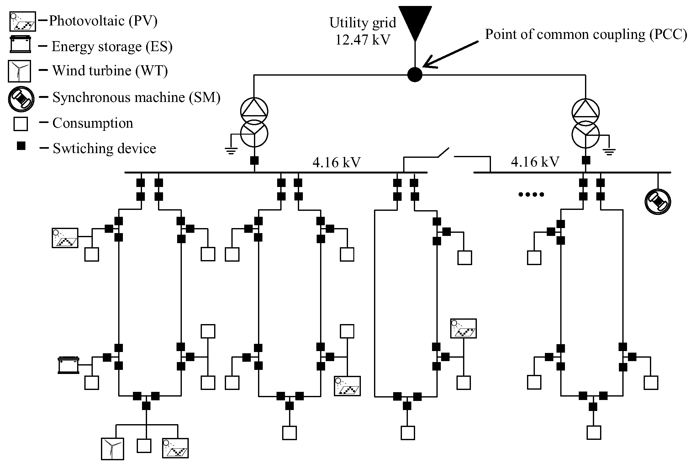
Microgrids thus emerged to systematically cope with the issues of resiliency and economics of power delivery systems. A microgrid is a small part of the power system, consisting of loads and DERs, that is connected to the utility grid at one point of common coupling (PCC), but that can disconnect from the grid and autonomously operate and feed its own load through DERs. Thus, microgrids enable systematic integration of DERs into small independent power systems, but also provide a pool of DERs, that can provide their aggregated power to distribution system operators for various services, especially regarding reliability, resiliency, and economic objectives [
1,
2].
An example of a real-life microgrid that represents a university campus in the USA is depicted in
Figure 1 [
23].
Finally, generation units within microgrids consist of different DER technologies, ranging from gas- or coal-fed synchronous generators, wind turbines, solar PVs, as well as different technologies of energy storages (batteries, flywheels, etc.). They can be directly connected to the grid, completely decoupled from the grid by an inverter, or in some cases partially decoupled, such as DFIMs. Fault currents of these DERs differ widely depending on a technology used [
10], and thus they should be properly modelled in order to have precise fault calculation results and consequently accurate input for the relay protection application.
In the following section, modelling of different DER technologies for fault calculation purposes is briefly reviewed and presented.
3. DER Models
There is a wide range of different resources which are connected to the distribution system, such as photovoltaics, wind turbines, energy storages and diesel gensets. Besides technology, their differences are shown in the manner that they are connected to the distribution system. However, all DERs can be sorted into four categories regarding modelling for fault calculations [
10]:
3.1. Synchronous Machines Directly Connected to the Grid
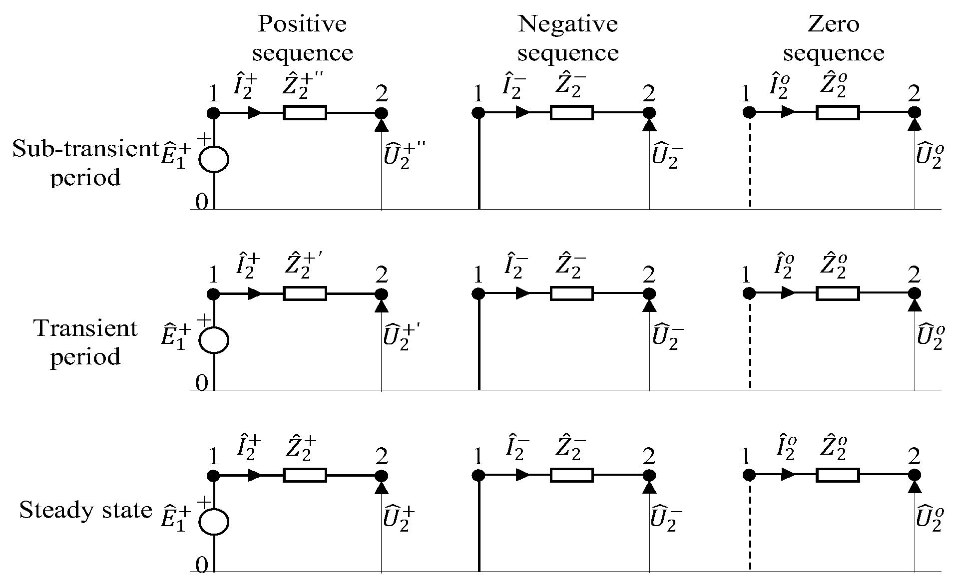
Synchronous machines’ models for fault calculations were well-known and established decades ago. In general, these models consist of ideal voltage sources behind (sub-transient, transient, or steady-state) impedances with the fact that in negative and zero sequence, the ideal voltage source is annulled as it is depicted in
Figure 2.
In sub-transient and transient periods, these DERs produce up to eight and five times their rated currents, respectively [
10].
Regarding the DER technologies that fall into this category are gas-fed generators, biogas units, combined heat and power units (CHP), etc.
3.2. Induction Machines Directly Connected to the Grid
Like synchronous machines, fault models for induction machines, directly connected to the grid, are well-known for more than half a century.
These models also consist of ideal voltage source behind impedances, but unlike the synchronous machines, there is no sub-transient period [
10]. In addition, there is no voltage source in the positive sequence circuit of the induction machine model after the transient period [
10]. The negative sequence model is the same as the positive, except the ideal voltage source in the transient period is annulled. Finally, for induction machines, stator windings are in most cases delta or ungrounded wye connected [
10] thus there is no zero-sequence contribution.
These DERs also produce high initial fault currents, but generally less than synchronous machines. Regarding DER technologies that fall into this category are mostly older versions of wind generators, so-called Type 1 and Type 2 wind turbines [
10].
3.3. Inverter-Based DERs
As IBDERs are connected to the network through inverters, their behavior is completely controlled by the inverter’s controller. In normal operating conditions, IBDERs, in most cases, operate with a unity power factor, in order to generate as much real power as possible [
9]. As every fault in a microgrid is accompanied by voltage dip at the IBDER’s connection point, IBDER controller must respond in order to satisfy various grid-code requirements for voltage stabilization.
After the inverter’s controller detects a fault occurrence, it limits fault current to a predefined value, and employs a predefined control strategy to manage the active to reactive fault currents ratio. In most cases, the IBDER injects a positive sequence symmetrical currents, even in case of unbalanced faults, and reacts to positive sequence voltage drops [
9]. The IBDER control strategies that manage fault currents are dictated by the requirements defined in specific grid codes, including the Fault Ride Through (FRT) and Reactive Current Injection requirements [
9].
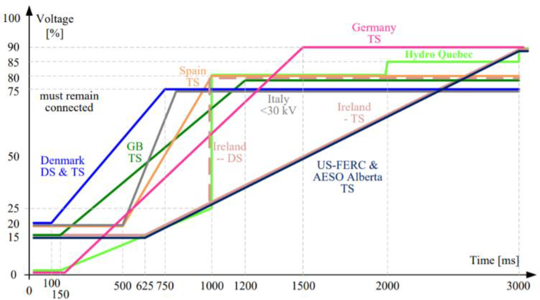
In
Figure 3, the FRT requirements of grid codes for various countries are shown [
9]. Different countries are marked with different colors. Time (in milliseconds) for how long an IBDER should stay connected to the grid in case of a fault is given on the X-axis, while the voltage at the IBDER’s connections (relative to the rated voltage) during the fault is given on the Y-axis.
While the values on threshold lines differ for different countries, the principle is the same: if the voltage at the bus to which an IBDER is connected stays above the threshold, the IBDER must stay connected to the grid during the fault. However, if the voltage drops below the threshold line, the IBDER should disconnect from the grid.
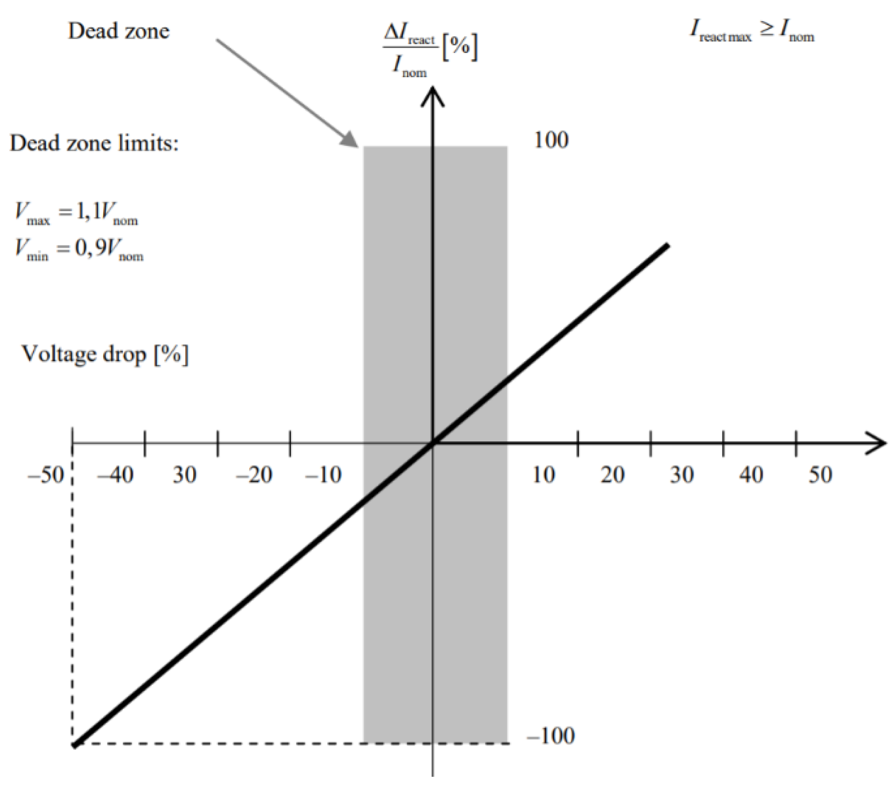
Grid codes require IBDERs to support faster voltage recovery in the system by injecting reactive power throughout the duration of a fault. In most cases, grid codes require IBDERs to provide reactive current with a contribution of at least 2% of the rated current per percent of the voltage drop [
9]; i.e., if the voltage drops to 50%, the reactive current should be at least 100% of its rated value. This requirement is presented in
Figure 4.
Nevertheless, when the inverter’s controller detects the fault, it must control IBDER’s fault current responses within strictly defined current limits to protect vulnerable power electronic devices [
9]. The current limit differs with different manufacturers but does not exceed 1.5 times the rated current. Therefore, in cases of severe voltage drops (more than 75%), their reactive currents cannot exceed this limit.
A very short sub-transient period in which the IBDER’s fault current is not limited is beyond the scope of this paper. However, this period is very important for the planning and selection stage of the protection equipment in the microgrids and will therefore be addressed in the authors’ future research.
In [
9,
10] highly accurate models for IBDERs during the faults, which consider the required characteristics of the IBDERs’ fault behavior, are proposed. The proposed models in the transient period consist of limited current sources with the ratio of their active to reactive parts dependent on the voltage drop on the IBDER’s terminals, as dictated by the FRT requirements. In this paper, the FRT requirements from the German Grid Code were chosen.
Regarding DER, the technologies that fall into this category are solar photovoltaics, Type 4 wind generators, batteries for energy storage, flywheels, etc.
3.4. Doubly-Fed Induction Machines
DFIM is the most challenging DER type for the fault calculation modelling, when large distribution networks are considered [
10]. This is because its fault response, and consequently models for the fault calculation purposes, highly depend on the severity of the fault (electrical distance from the DFIM to the specific fault location) and on the device used for protection of the power electronics [
10].
In cases of severe faults which cause high voltage drops at the DFIMs’ connection points, the protection device aimed to protect power electronics, short-circuits the rotor, and the DFIM’s fault response becomes the same as the induction machine’s. However, when the fault happens far from the DFIM’s connection points, and the voltage drop is not significant, DFIM can maintain its pre-fault control strategy and its fault response is similar to the IBDER (controlled and limited fault current) [
10].
As the microgrid is usually small, and the electrical distance between nodes are in most cases low, in this paper, the worst-case scenario—the DFIM loses its control during the fault and behaves as an induction machine—will be assumed. Thus, the induction machine models will be used to represent DFIMs during the fault.
The DFIM technology is mainly used in wind generation, for so-called Type 3 wind turbines [
10].
At the end of this section, it is important to sum up that there is a substantial difference in behavior between traditional and emerging DERs during the fault, which will be properly considered in the fault analysis presented in this paper.
4. Short-Circuit Calculation Procedure
Generally, in Short-circuit calculations, the faulted system state represents a superposition of a pre-fault state and a ∆-circuit state [
26,
27]. As pre-fault state is already known from load flow calculation, the Short-circuit calculation reduces to the calculation of the ∆-circuit state [
26,
27]. The most important attribute of traditional ∆-circuit is that it contains only one ideal source, connected to the faulted node, while the rest of the circuit is passive [
26,
27].
However, because of the increasing number of connected IBDERs, the traditional ∆-circuit concept cannot be retained for calculations in emerging distribution systems. As IBDERs have their own control strategies for supporting the network during the faults, their fault currents regularly exceed the values of their pre-fault currents. These differences between IBDERs’ fault currents values and their pre-fault currents values represent excess currents [
9]. In order to properly consider IBDERs’ contribution to fault current, it is necessary to inject the excess currents in the ∆-circuit. Thus, the ∆-circuit gets new ideal sources connected to nodes where these IBDERs are connected to the system. The ∆-circuit obtained in this way is termed the Generalized ∆-circuit [
10]. It is important to emphasize that there are no differences between traditional and Generalized ∆-circuit in negative and zero sequence, because negative and zero sequence components of excess currents are equal to zero. Only excess currents’ direct sequence component exists in Generalized ∆-circuit, because IBDERs are controlled in a way that they supply only positive sequence currents [
9]. The excess currents of IBDERs are calculated as follows:
where
represents the set of IBDERs whose excess currents
are greater than zero. The fault currents from IBDERs which are marked with
are calculated using IBDER’s model from [
9]. During this calculation, the IBDERs’ control strategies are taken into consideration. The pre-fault currents
are known from load flow calculation.
In this paper, all four solid short-circuits are considered: phase to ground (L-G), phase to phase (L-L), two-phase to ground (L-L-G) and three-phase (to ground) (L-L-L-G). The equations for calculating short-circuit currents’ sequence components, at the short-circuit location (bus k), are given in
Table 1 [
19].
Where:
, , represent sequence domain Thévenin impedances seen from bus k
is the known pre-fault phase a voltage at bus k.
As demonstrated in [
28], the excess currents of IBDERs have a minor influence on the short-circuit currents at the fault location. The short-circuit currents calculated by utilizing the equations listed in
Table 1 have an inaccuracy less than 2%. Hence, with the intention to keep the simplicity of the well-established equations from the table, application of these will remain for calculation of the short-circuit currents at the fault location in the Generalized ∆-circuit. Nonetheless, the fault current flow in the whole system is significantly influenced by the excess currents. By overlooking this influence, protection equipment settings and coordination as well as protection of IBDERs’ power converters could be seriously affected. Consequently, their influence must not be omitted while the calculation of the Generalized ∆-circuit state is performed.
As in traditional ∆-circuit there is a sole ideal source connected to faulted node, while the rest of the circuit is passive, after calculation of the current at the fault place, all three sequence states of the Traditional ∆-circuit can be easily calculated as follows:
However, as established above, in the positive sequence of Generalized ∆-circuit, in addition to the ideal source connected to the faulted node, there are also ideal sources at every node in which the IBDERs are connected. Thus, (2) and (3) can be used for calculating only negative and zero sequences. The positive sequence of the Generalized ∆- circuit must be calculated by injecting short-circuit currents at the fault location plus injecting the excess currents at every location of the positive sequence circuit where IBDERs are connected. In [
10], the original Backward Forward Sweep (BFS) procedure from [
21] is modified by injecting the excess currents at every location where IBDERs are connected. In this paper, the modified Improved Backward Forward Sweep (IBFS) procedure from [
10] was used for SCC. More details regarding the procedure can be found in [
10,
21].
5. Results
To test and measure the short-circuit current level for various fault types and locations, a realistic microgrid testbed has been developed and it is depicted in
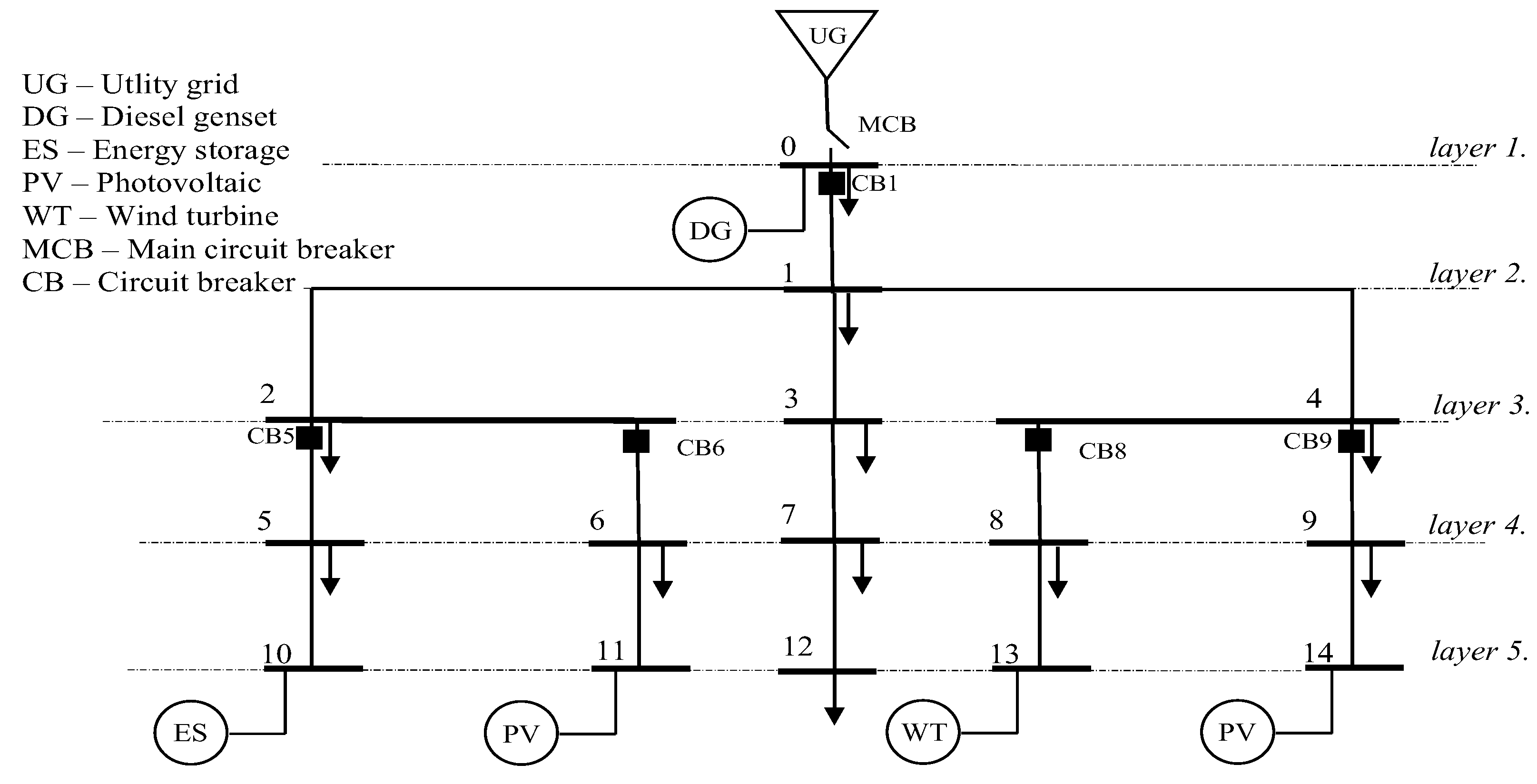
Figure 5.
The microgrid consists of 15 three-phase busses, where the bus 0 is the microgrid’s Point of Common Coupling (PCC), in which it is connected to the utility grid. There are equal loads of 100 kVA in busses 0, 1, 2, 3, 4, 5, 6, 7, 8, 9 and 12. Besides that, there are five different DERs located in busses 0, 10, 11, 13, and 14. The specific DER technologies are described for each DER in
Figure 5. The DER powers are as follows: SDG = 700 kVA, SES = 100 kVA, SPV = 100 kVA, SWT = 100 kVA. The utility grid’s equivalent impedance is
= (0.128380 + j 0.235690) Ω. All lines have the same parameters, equal to:
The lines also have the same lengths equal to 0.075 km. The main circuit breaker that connects the microgrid to the utility grid is marked with MCB in
Figure 5, while five other breaking devices, located at the critical positions, are marked with CB1, CB5, CB6, CB8, and CB9, respectively. The nature and technology of these devices (breaker, fuse, etc.) are beyond the scope of this paper. Rather, the fault currents at their locations will be calculated and consequently, valuable conclusions regarding the required improvements for fault analysis and relay protection calculations of microgrids in general will be derived
Before the fault analysis, a pre-fault state calculation was performed, and results of load flow are presented in
Table 2.
Different fault types in various busses are analyzed, but to avoid overburdening the paper, the results are presented only for the three-line-to-ground (3LG) fault in bus 9 in both grid-connected and islanded modes of operation. Results for faults in other busses, and of other types, are available upon request. The fault calculation procedure from [
10] was used for all tests. All calculation procedures were in-house developed and programmed in FORTRAN 2018. The results for the complete faulted states of the microgrid in grid-connected and islanded modes of operation are presented in
Table 3 and
Table 4, respectively. Fault currents at the breaking devices’ locations and at the closest IBDER’s location are written in bold in the tables below.
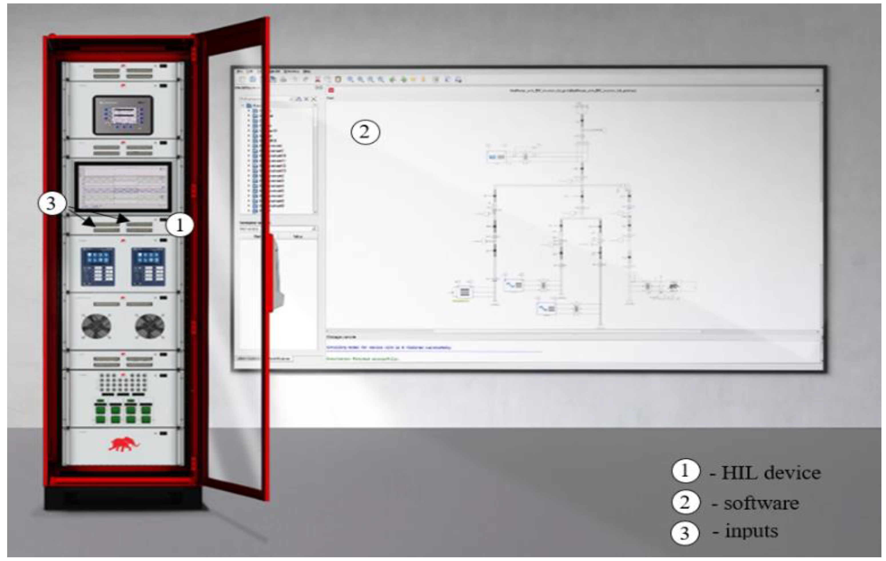
To validate the accuracy of the obtained results, the same microgrid testbed is developed using a state-of-the-art hardware-in-the-loop setup from the Typhoon HIL manufacturer, which is depicted in
Figure 6 [
29]. Electrical part of the network is consisted of high accuracy models from Typhoon HIL library including DER models, whereas signal processing part of the network is realized through the real, physical, inverter controllers which are physically connected to Typhoon HIL inputs and mapped to the input signals of appropriate DER inverters which are the components of a software model. This allows real physical controllers to be able to control DER behavior during short circuit faults and provides a highly realistic testbed. For inverter controller, there is no difference between being connected to the Typhoon HIL and to the real microgrid. Inverter control strategy which is in accordance with the FRT requirements from the German grid code are implemented in physical controller, thus responses of currents which represent IBDERs’ contributions to the fault current, obtained with the described setup, fully correspond to the real-life fault responses of IBDERs.
As the results obtained with the Typhoon HIL setup are in time-domain and describe dynamic behavior of IBDERs during the fault, it is necessary to limit the observation only on transient period and to transfer obtained values from time domain to steady state (complex) domain in order to compare these results with the results obtained with the in-house-developed software.
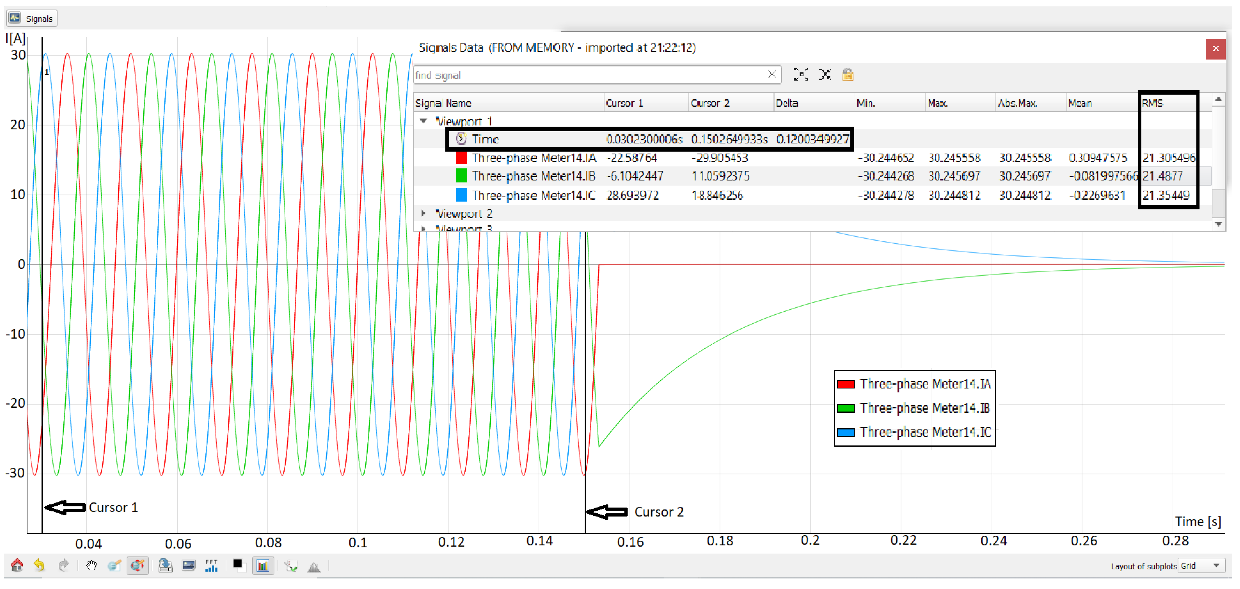
An example of the fault current response of the IBDER connected to the bus 14, which describes its behavior in case of a 3LG short-circuit at the bus 9, obtained with Typhoon HIL in time-domain, observed only in transient period is depicted in
Figure 7. Values from the Signal Data window which is presented in a row named Time and columns named Cursor 1, Cursor 2 and Delta describe which time period is analyzed. As it can be seen from
Figure 7, after a short initial sub-transient period (approximately 0.03s), which is beyond the scope of this paper, the IBDER contributes with a fault current of 21.3 [A] (RMS value) through branch 14 to the fault current. As it is presented in
Table 2, value of the pre-fault current through branch 14 was 13.83 [A], thus the value obtained with Typhoon HIL setup proves that IBDER’s current during the fault is indeed limited to 1.5 times its rated value.
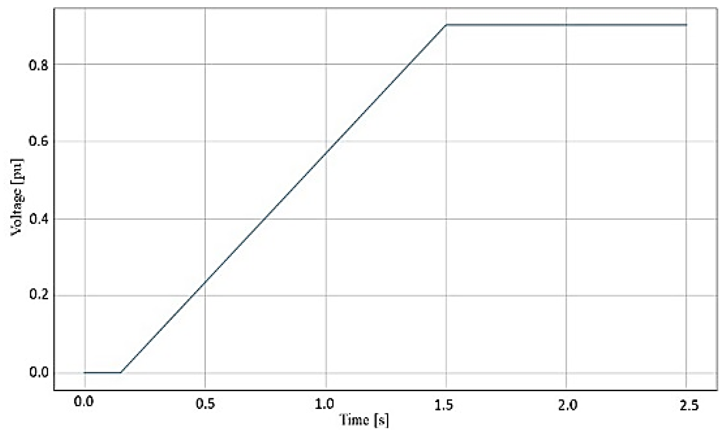
The FRT requirements from the German grid code standard which were used for IBDER control during this research are depicted in
Figure 8. In a case of a 3LG short-circuit at bus 9, the value of a voltage at the bus 14 will be equal to zero. It is clear from
Figure 8 that the IBDER will contribute to the fault current during the first 0.015 s. After that period, IBDER will disconnect from the network. This can also be observed in
Figure 7.
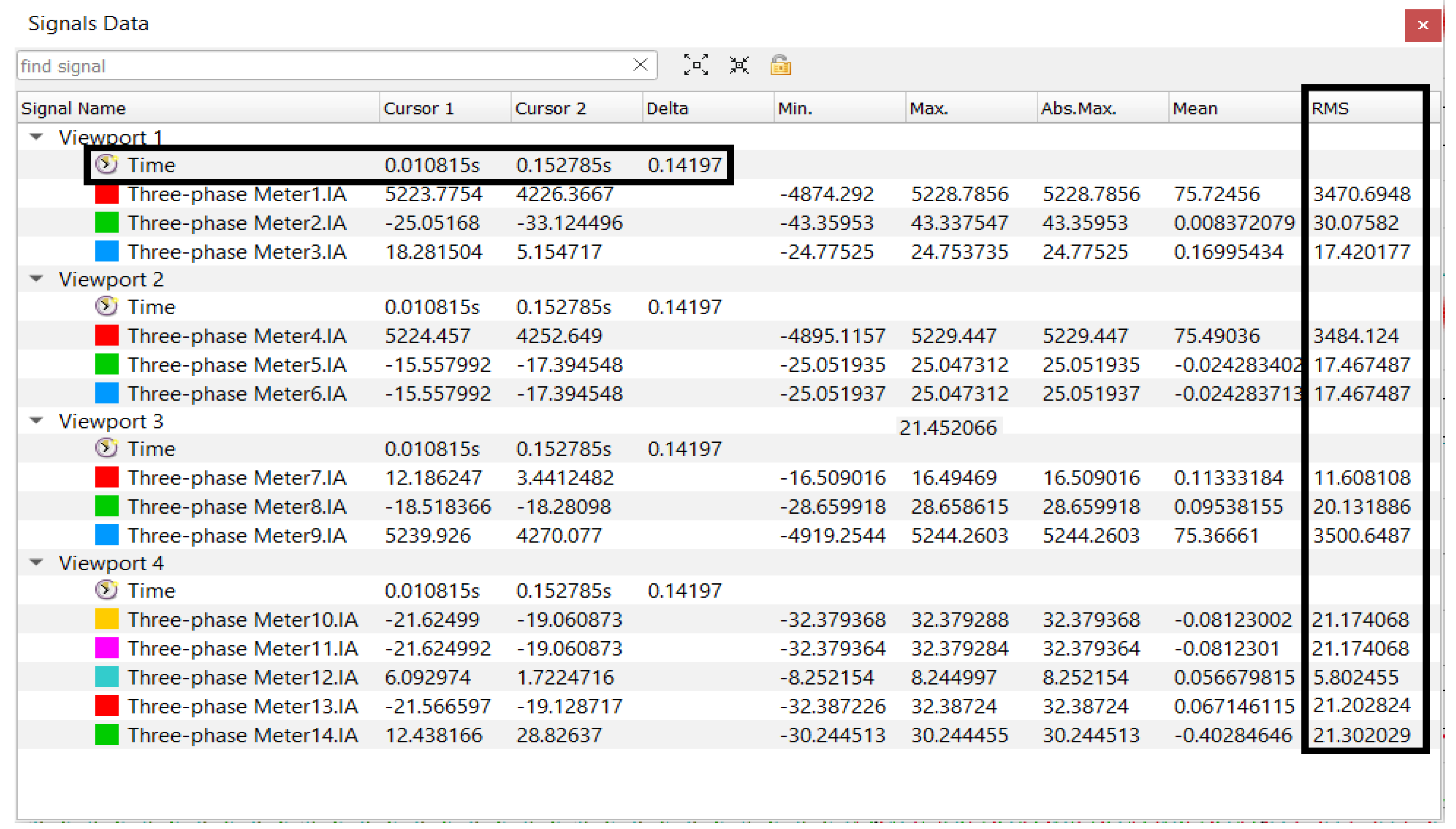
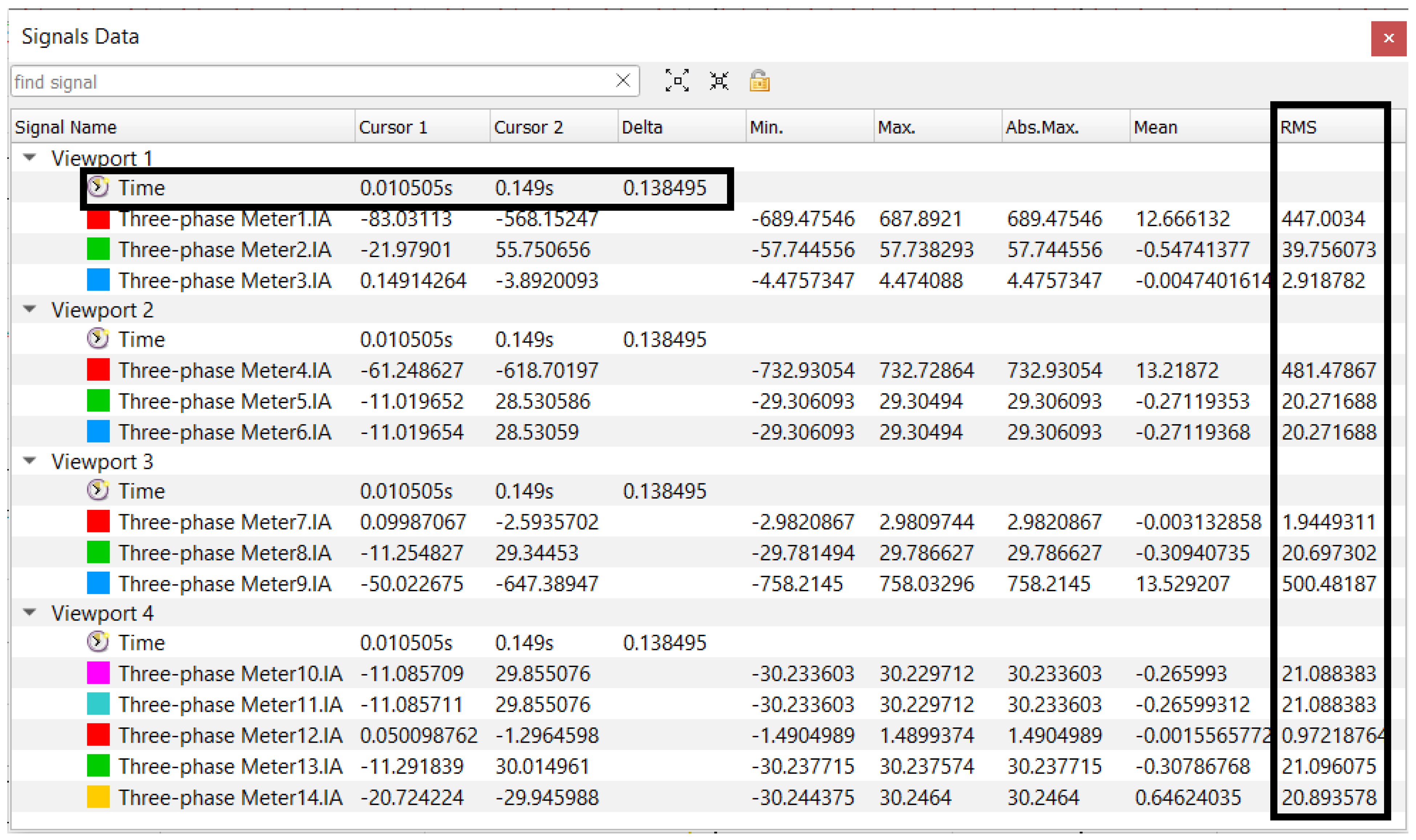
The results for the complete faulted states of the microgrid in grid-connected and islanded modes of operation obtained by Typhoon HIL are presented in
Figure 9 and
Figure 10, respectively.
The comparison of the results at the breaking devices’ locations and at the closest IBDER location, from the in-house software and Typhoon HIL, along with the highest differences in the results obtained by two platforms in both modes of operation, are presented in
Table 5.
6. Discussion
From the presented results, the following can be derived:
From
Table 3 and
Table 4, the differences between fault currents for the 3LG fault, in grid-connected and islanded modes are huge. If we analyze the fault currents at the protective devices’ locations, it is obvious that their magnitudes differ widely, with the fault currents in grid-connected mode being up to 8.2 times higher than in the islanded mode.
Based on the results from
Table 3 and
Table 4, it is obvious that standard “set and forget” relay protection methods cannot be used for microgrids aimed to operate in both, grid-connected and islanded modes. Rather, novel methods for adaptive relay protection shall emerge, that would monitor the grid conditions in real-time, and adapt the protective equipment settings based on the real-time data. This is one of the authors’ future research directions, derived from the results obtained during this research.
Based on the results from
Table 5, it can be concluded that the results for the grid-connected mode, obtained by in-house-developed software solution match well with the results from Typhoon HIL’s hardware-in-the-loop device. The differences are less than 2%. However, for the islanded mode, the differences in the obtained results are much higher and reach up to 15.36%. This is because the fault calculation procedure used for this research [
10], is specially aimed for radial distribution networks, with one main power source (slack bus) and DERs that are much weaker than the main source. This works very-well for the grid-connected mode where the utility grid is the main source, but provides less accurate results for the islanded mode, where DERs share the entire load among themselves. Thus, a novel fault calculation procedure, that will work well and provide highly accurate results regardless of the operation mode, shall emerge. This is the second important future research direction that is derived from the results of the current research.
Finally, the third direction for the future research will be focused on analyzing a short period immediately upon the fault occurrence, in which the fault currents of IBDERs are not limited. In addition, the influence of these currents on the protective equipment selection and planning process will be analyzed.
To summarize the presented research, our main aims during this research were: (1) To develop a highly realistic microgrid testbed and by simulating different fault types at different locations during distinct operation modes, thoroughly analyze the fault currents inside the microgrids supplied by various sources; (2) To compare the results of the fault currents obtained using the testbed within the state-of-the-art HIL environment with the results obtained by short-circuit calculation procedure aimed at distribution grids (most often used for microgrid fault calculations), and derive conclusions regarding its applicability. Consequently, the fault currents inside the microgrid are precisely quantified, huge differences relative to the operating mode are noted, and finally based on the presented results, the applicability of the short circuit calculation procedures aimed at distribution grids is proven to be very limited when microgrids are considered.
Based on these results, three important research directions are derived: (1) A new short circuit calculation procedure that will be sufficiently robust and applicable for both operating modes of the microgrid should be developed; (2) Based on the developed short circuit calculation procedure, a new adaptive relay protection method capable of protecting the microgrid regardless of the operating mode should emerge; (3) For the purpose of selecting the protection equipment and planning the upgrades of the microgrid, the initial (sub-transient) fault period in which the fault currents of IBDERs are not limited should be thoroughly analyzed.
7. Conclusions
In this paper, a thorough analysis of the fault current values in the emerging microgrids is performed. Both grid-connected and islanded modes are thoroughly analyzed, and high differences in fault currents depending on the operational mode are detected. These differences can adversely affect the relay protection of the microgrid, causing the microgrid to be vulnerable and unprotected in some critical cases.
Moreover, it is noted that fault current procedures aimed at radial distribution networks, that are mostly used for microgrids’ fault calculations, are not completely suitable for microgrids that are aimed at operating in both grid-connected and islanded modes.
Based on the presented research, it can be concluded that because of microgrids’ specific modes of operation and a tendency of a massive penetration of IBDERs within microgrids, two crucially important areas—fault calculations and relay protection settings, cannot be performed by using traditional calculations aimed at distribution systems. As the microgrids’ popularity rises, and consequently as their penetration around the globe rises, these issues shall be properly considered, and the appropriate methods shall urgently emerge.


