Article

Monolithic Perovskite-Carrier Selective Contact Silicon Tandem Solar Cells Using Molybdenum Oxide as a Hole Selective Layer

1
Department of Materials Science and Engineering, Korea University, Seoul 02841, Korea
2
KU-KIST Green School, Graduate School of Energy and Environment, Korea University, Seoul 02841, Korea
3
National Agenda Research Division, Korea Institute of Science and Technology (KIST), 5, Hwarang-ro 14-gil, Seongbuk-gu, Seoul 02792, Korea
4
Meiji Renewable Energy Laboratory, Meiji University, 1-1-1 Higashimita, Tama-ku, Kawasaki 214-8571, Japan
*
Authors to whom correspondence should be addressed.
Energies 2021, 14(11), 3108; https://doi.org/10.3390/en14113108
Submission received: 12 April 2021 / Revised: 16 May 2021 / Accepted: 24 May 2021 / Published: 26 May 2021
(This article belongs to the Special Issue Recent Advances in Thin Film Solar Cells)

Abstract

:
Monolithic perovskite–silicon tandem solar cells with MoOx hole selective contact silicon bottom solar cells show a power conversion efficiency of 8%. A thin 15 nm-thick MoOx contact to n-type Si was used instead of a standard p+ emitter to collect holes and the SiOx/n+ poly-Si structure was deposited on the other side of the device for direct tunneling of electrons and this silicon bottom cell structure shows ~15% of power conversion efficiency. With this bottom carrier selective silicon cell, tin oxide, and subsequent perovskite structure were deposited to fabricate monolithic tandem solar cells. Monolithic tandem structure without ITO interlayer was also compared to confirm the role of MoOx in tandem cells and this tandem structure shows the power conversion efficiency of 3.3%. This research has confirmed that the MoOx layer simultaneously acts as a passivation layer and a hole collecting layer in this tandem structure.

1. Introduction

The conversion efficiency of silicon solar cells, which occupy the largest share of the photovoltaic market [1], is approaching the maximum theoretical efficiency [2]. Currently, the Si champion cell is 26.7% [3], due to its low radiation rate, the efficiency of Si solar cells is limited to 29.4%, which is ~4% below the Shockley–Queisser limit [4]. Hence, several research groups are involved in the development of perovskite–silicon tandem solar cells with enhanced optical absorption in the short wavelength band [5]; a group of Young Investigator Group Perovskite Tandem Solar Cells at the Helmholtz-Zentrum Berlin reports a high efficiency of 29.15% for perovskite–silicon solar cells [6]. Various silicon bottom cell concepts are being evaluated to further improve the conversion efficiency of perovskite–silicon tandem solar cells [7]. In this study, tandem cells are fabricated using carrier selective contact silicon solar cells as bottom structures. Molybdenum oxide is used as a carrier selective contact material in the bottom cells, which can play the role of a hole transport layer without a conventional p-n junction.
The concept of carrier selective contact in silicon solar cell research has attracted considerable attention in recent years. The highest efficiency of monocrystalline silicon solar cells is achieved using the heterojunction with intrinsic thin layer (HIT) cell structure, in which the solar cell is fabricated using an intrinsic amorphous silicon passivated contact layer [3,8]. In addition, devices using passivating contacts of polysilicon called tunnel oxide passivated contact (TOPCon) [9] and polycrystalline silicon on oxide (POLO) [10] show high efficiency. Research on carrier selective contact solar cells, which effectively collect photogenerated carriers by depositing other materials on silicon without a substrate doping process, has been extensively carried out since the 1970s [11,12,13,14,15]. Recently, a high value of carrier lifetime can be obtained by improving the silicon interface passivation characteristics [16]. Hence, studies on carrier selective contacts using carbon-based materials [17,18] and metal oxides such as TiO2, ZnO, and MoOx, which can be easily deposited, have attracted renewed attention [19,20,21]. Unlike conventional p-n junction cells with built-in electric fields formed by a doping process to separate photogenerated carriers, the carrier selective contact structure separates the carriers by band bending generated between the material being contacted and the silicon. The carrier selectivity of these layers depends on the electronic structures of the materials deposited on silicon [22,23].
In this study, MoOx was deposited on a silicon substrate through evaporation to form a hole selective contact, and the passivation characteristics of MoOx were studied. MoOx has a wide bandgap and a considerably large work function compared to other metal oxides [24]. The schematic diagram of the energy band of the MoOx/n-Si interface on contact is shown in Figure 1a. MoOx selective contact has been interpreted as two possible transport mechanisms in the contact area [25]: (1) band-to-band tunneling, in which the carriers directly tunnel the bands and (2) trap-assisted tunneling, in which the carriers tunnel through the trap sites within the bandgap of the MoOx [26]. The value of the work function of MoOx changes depending on the presence of oxygen vacancy of the layer [27], and the work function value influences the interface inversion for carrier separation [28]. As shown in Figure 1b, the hole selective contact silicon cell using the molybdenum oxide layer worked without homojunction and additional passivation layers. When a layer of MoOx with a high work function is deposited on n-type silicon, an inversion layer similar to the Schottky barrier is formed, separating electron-hole pairs [29]. The electrons photogenerated from the silicon bulk are blocked by the barrier at the MoOx/n-Si interface and flow down to reach the opposite electrode and the holes recombine at the MoOx/n-Si interface. Since the inversion layer at the silicon interface is affected by the electronic properties of the deposited material, various metal oxides with high work functions are deposited on silicon, which are being studied as carrier selective contact materials [30].
MoOx with various structures have been studied to create hole selective contact in silicon cells to achieve high efficiency [31,32], and an efficiency of more than 20% has recently been reported [33]. However, monolithic perovskite–silicon tandem structures using carrier selective contact silicon cells have not yet been reported. In this study, monolithic perovskite-carrier selective contact silicon tandem cells without a conventional p-n junction were fabricated using two types of solar cells, as shown in Figure 1b. Since the structure can also be fabricated without an ITO layer in terms of band alignment, structures both with and without the ITO layer were studied.

2. Materials and Methods

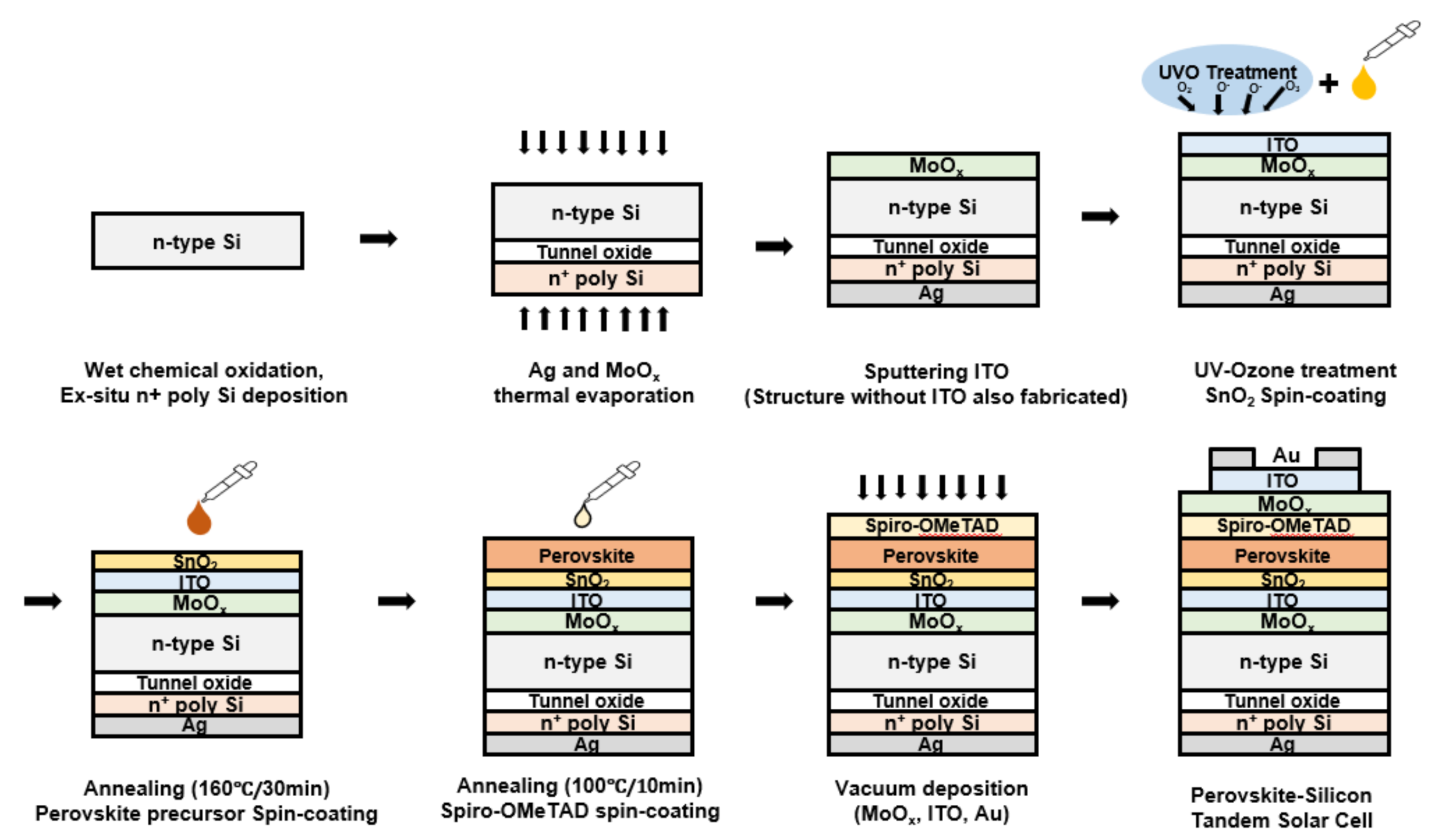
2.1. Fabrication of Monolithic Perovskite-Carrier Selective Contact Silicon Tandem Solar Cell

A hole selective contact silicon solar cell was prepared using an n-type float-zone (FZ) silicon wafer (100) with a thickness of ~280 µm and a resistivity of ~1 Ωcm. The wafers were subjected to the conventional cleaning process of the Radio Corporation of America (RCA) using deionized water, NH4OH, HCl, and H2O2. After RCA cleaning, as shown in Figure 2, a silicon oxide layer with a thickness of ~1.2 nm was grown on the wafer surface via wet chemical oxidation using H2O2. Thickness of the silicon oxide thin film was confirmed by ellipsometer measurement with a reflective index N of 1.45. Subsequently, ~300 nm of intrinsic polysilicon was deposited on the silicon oxide surface using low-pressure chemical vapor deposition (LPCVD) equipment at 600 °C. The intrinsic polysilicon layer was doped using POCl3 diffusion at 925 °C after 45 min of ramp-up time from 500 °C in a furnace. The front side n+ poly Si layer was etched by dipping 80 °C Tetramethylammonium hydroxide (TMAH, 20 wt. % in H2O, Aldrich, St. Louis, MO, USA) solution and the front side tunnel oxide layer was etched by dilute HF solution. Next, MoOx layers were deposited by thermal evaporation using molybdenum (VI) oxide powder (99.99% purity, Sigma Aldrich), and ITO films were prepared by plasma sputtering. The samples were subjected to UV–ozone treatment for improving the wettability and removing contamination. Then, a compact SnO2 layer was deposited by a solution process using a spin coater, and the spin-coated film was annealed at 160 °C for 30 min. The perovskite precursor solution was spin-coated onto the SnO2 layer while anhydrous diethyl ether, to treat the layer during the anti-solvent process [34], was slowly dripped on top of the substrate. Subsequently, the film was annealed at 100 °C for 10 min to obtain a dense CH3NH3PbI3 film. The spiro-OMeTAD layer was spin-coated by dissolving spiro-OMeTAD (Merck, Kenilworth, NJ, USA) in a mixed solution of chlorobenzene (anhydrous, 99.8%, Sigma-Aldrich), 4-tert-butylpyridine (96%, Aldrich), and Li-TFSL (99.95%, Aldrich). Next, the MoOx buffer layer was deposited by thermal evaporation, and the ITO transparent electrode was deposited by DC magnetron sputtering. The front gold electrode was deposited through a thermal evaporator using a pattern-shaped mask.

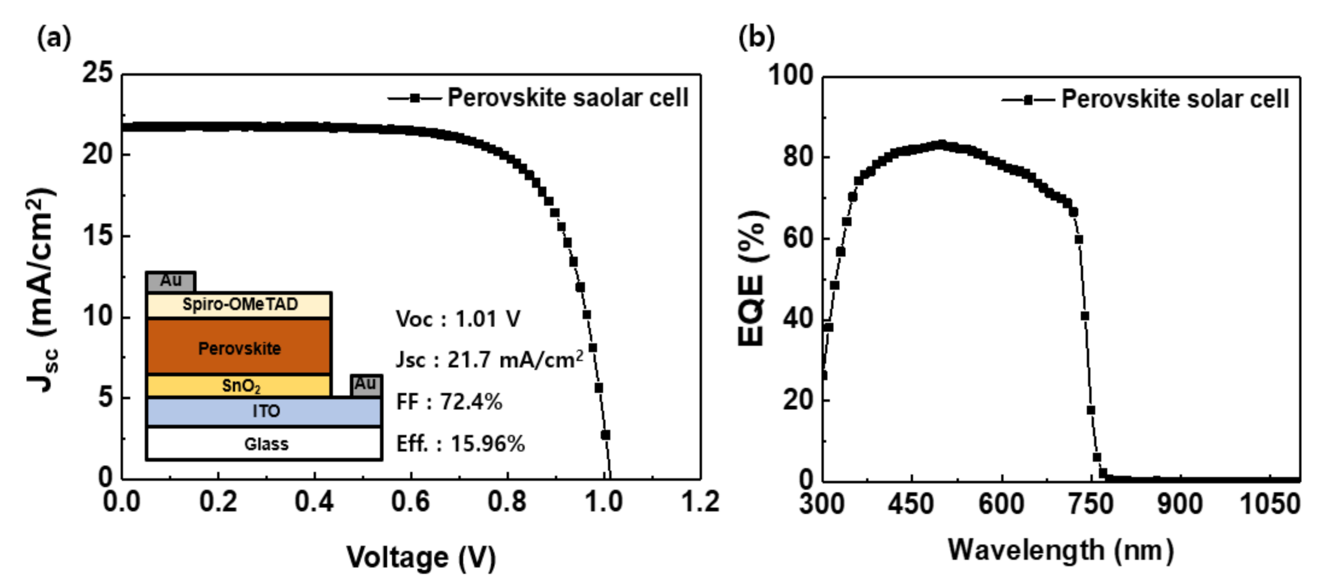
2.2. Hole Selective Contact Silicon Solar Cell and Perovskite Solar Cell

The fabrication of the MoOx hole selective contact silicon cell was carried out using the same steps shown in Figure 2 up to the sputtering ITO process. A silver electrode was deposited on the front side of the sample by thermal evaporation to complete the silicon solar cell. An ITO patterned glass substrate was used to fabricate the perovskite solar cell, and the sequence of steps from the UV–ozone treatment, as depicted in Figure 2, was followed.

2.3. Sample Measurement

To evaluate the passivation quality of the symmetric MoOx and tunnel oxide/P doped polysilicon passivated layers, the implied Voc of the samples under 1-sun illumination (xenon flash lamp) was determined using a WCT-120 Sinton Instruments tool in the QSS mode according to the following equation proposed by Sinton [35]:
V o c , i m p l i e d = k T q ln N D + n n n i 2
where kT/q is the thermal voltage, ND is the doping concentration, ∆n is the excess carrier concentration related to the effective minority carrier lifetime, and ni is the intrinsic carrier concentration. The J-V tests were carried out using a Keithley 2400 Source meter under the illumination of an AM 1.5 G solar simulator (100 mW/cm2). An EQE testing system consisting of a monochromator was used to scan the UV–Vis–Infrared spectrum.

3. Results

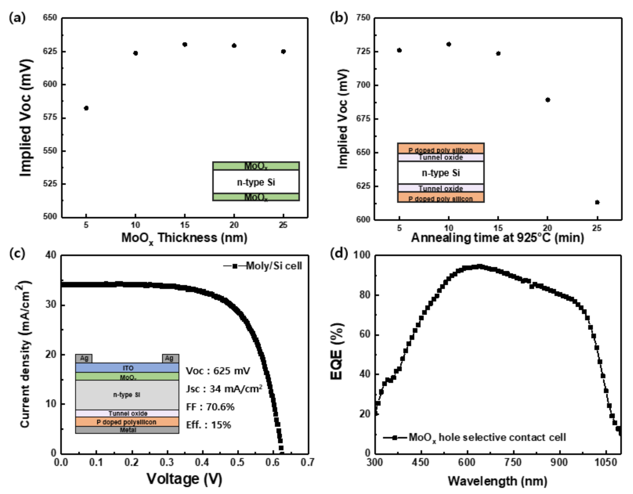
3.1. Molybdenum Oxide Hole Selective Contact Si Solar Cell

MoOx film and phosphorus(n+) doped polysilicon layers were optimized to fabricate a carrier selective contact silicon solar cell for use as a bottom cell in tandem solar cells. It is important to optimize the thickness of the MoOx layer. This is because the layer induces silicon band bending and at the same time, acting as a passivation layer without any interlayer. Figure 3a shows the implied open-circuit voltage (Voc) values of the MoOx/Si/MoOx symmetrical lifetime samples. The MoOx layers were deposited with thicknesses in the range of 5 to 25 nm on both sides of an n-type silicon wafer without any passivation layers, such as an amorphous silicon or a thin oxide layer. The implied Voc value increases as the thickness of the MoOx layer increases up to 15 nm, which reaches a maximum value of 630.3 mV. With further increase in the film thickness, the implied Voc value slightly decreases while maintaining a certain degree of passivation. The MoOx dielectric layer deposited on the silicon wafer prevents surface recombination and at the same time shows the effect of increasing the carrier lifetime and implied Voc due to the band bending according to the thickness of a hole selective material [36].
To improve the bottom silicon cell characteristics, the TOPCon structure, which is widely studied as a carrier selective passivated contact structure showing high-quality passivation properties [37,38,39], was optimized. We fabricated n+ poly-Si/SiOx/Si/SiOx/n+ poly-Si symmetrical lifetime samples. The sample structure is shown in the inset of Figure 3b. After depositing intrinsic polysilicon on the chemical tunnel oxide passivated n-type silicon wafer, phosphorus doping was performed in a tube furnace at temperatures in the range of 875–1000 °C using POCl3 as the source. Implied Voc values were measured after an additional hydrogenation process, which can largely enhance the passivation quality of the TOPCon structure [40]. The lowest value of recombination current density was obtained after phosphorus diffusion at 925 °C, with the time varying from 5 to 25 min, as shown in Figure 3b, and a maximum implied Voc of 730.6 mV was obtained after 10 min diffusion at 925 °C. These high properties of the rear passivated contact structure improve the qualities of the entire bottom cell, even if the front MoOx passivation property is quite low.
After applying the above two optimized carrier selective contacts to Si substrates, a transparent ITO electrode and a patterned Ag electrode were deposited on the front MoOx hole selective contact layer and a full area Ag electrode was deposited on the rear n+ poly-Si/SiOx electron selective contact layer, as shown in the inset of Figure 3c to fabricate a 1 × 1 cm2 carrier selective contact solar cell. For these solar cells without a p-n junction, the best conversion efficiency of 15% was achieved with a Voc of 625 mV, current density of 34 mA/cm2, and fill factor (FF) of 70.6%. Various hole selective contact silicon solar cells using an MoOx layer showed high conversion efficiencies (Table S1). The open-circuit voltage value of our cell using MoOx as an induced junction without any interlayer, such as a-Si, silicon oxide on a flat surface, is comparable to other groups. The fabricated Si solar cells have planar surfaces for stacking a perovskite solar cell. Therefore, the fabricated Si solar cells may have the benefit of higher Voc values but the disadvantage of lower Jsc values compared to Si solar cells with pyramid textured surfaces [41,42]. This is due to the higher light absorption but a higher number of dangling bonds of pyramid textured surfaces. Figure 3d shows the external quantum efficiency (EQE) of the fabricated Si solar cell in the wavelength range of 300 to 1100 nm. The EQE obtained in the wavelength range of about 600–800 nm is more than 80%. In the longer wavelength region, the EQE value tends to decrease due to the parasitic absorption of a 300 nm thick doped polysilicon layer. The EQE can be enhanced by reducing the thickness of a polysilicon layer and improving light reflection by a rear metal electrode [43]. The fabricated carrier selective contact silicon solar cell using MoOx in this study requires additional heat treatment to recover surface damage from the sputtering process [44] and to improve resistivity of the top ITO layer. However, the annealing process above 200 °C reduces the oxygen/Mo ratio and work function of the thermal evaporated MoOx [45], which can affect the voltage drop by reducing the band bending at the silicon interface. This structure still has some room to improve voltage and FF through the optimized annealing condition. It is expected that a high-efficiency cell can be fabricated by inserting a dielectric interlayer.

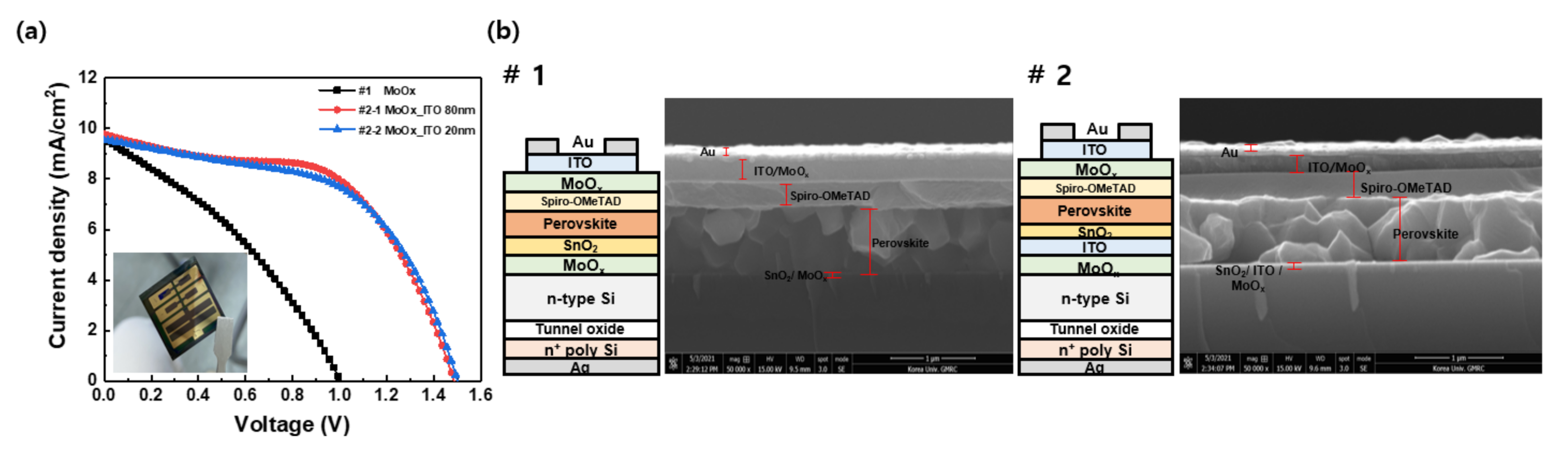
3.2. Tandem Solar Cells

The cell characteristics of the perovskite solar cells (PSCs) are shown in Figure 4. Figure 4a shows the J–V curve, and Figure 4b shows the EQE data of the fabricated perovskite cell in the wavelength range of 300–1100 nm. The PSC showed a conversion efficiency of 15.96% with an open-circuit voltage of 1.01 V, current density of 21.7 mA/cm2, and 72.4% FF. The EQE data show that the perovskite cell absorbs light only in the wavelength range of 300–750 nm, and the EQE value is more than 70% in the wavelength range of approximately 350–650 nm. To further increase the light absorption at shorter wavelengths, the bandgap of the perovskite was optimized and then applied to a tandem cell. The bandgap was increased from ~1.55 to ~1.65 eV by changing the composition of perovskite (Figure S2).
Figure 5a shows the light-induced current-voltage (LIV) characteristics of monolithic perovskite-carrier selective contact silicon tandem solar cells using MoOx as a hole selective contact. The solar cell without an ITO interlayer (#1) exhibited a PCE of 3.3%, and by using 80 and 20 nm-thick ITO interlayers (#2), the efficiency increased to 8.0 and 7.8%, respectively. The specific structures and cross-section SEM data of the fabricated tandem cells are shown in Figure 5b. In the structure without the ITO interlayer (#1), the MoOx film appears to be degraded, as UV–ozone treatment was performed before carrying out the SnO2 solution process [46]. In the case of samples with an ITO interlayer, structure #2 shows higher conversion efficiency as it prevents MoOx from degradation during UV–ozone treatment. Meanwhile, sample #2-1 and #2-2 have ITO interlayer thicknesses of 80 and 20 nm, respectively. Sample #2-1, with an 80-nm-thick ITO interlayer, showed lower Voc and higher FF compared to the sample #2-2 with a 20-nm-thick ITO interlayer. (Table S2) This may be due to higher sputtering damages during longer sputtering times. To increase the current of these tandem solar cells, current matching between the perovskite and the carrier selective contact silicon cell needs to be further studied.
The monolithic perovskite-carrier selective contact silicon tandem solar cell showed the highest efficiency of 8%, with a Voc of 1.485 V, Jsc of 9.77 mA/cm2, and 55.05% FF when 15 nm-thick MoOx and 80 nm-thick ITO layers were deposited as in cell structure #2. Both cell structures (#1 and #2) were confirmed to be capable of being driven by tandem cells. The Voc, Jsc, and FF are expected to improve with dry processing, current matching, and heat treatment optimization.

4. Conclusions

In this study, a carrier selective contact silicon cell using MoOx, instead of a p-n homojunction structure, was introduced to a monolithic perovskite–silicon tandem cell for the first time. Through the monolithic perovskite–silicon tandem solar cells, it was shown that the proposed new structure worked as a tandem solar cell. In the case of the bottom silicon solar cell, the carrier selective contact structure was optimized on the silicon cell using MoOx to the rear tunnel oxide passivated contact. The maximum implied Voc values were 630.3 and 730.6 mV, respectively, in the (15 nm-thick) MoOx/Si and poly-Si/SiOx/Si symmetric structures. For subsequent processes such as spin-coating, a polished surface was used to fabricate tandem solar cells, and a 15% carrier selective contact silicon solar cell was obtained. The bottom solar cell is expected to improve Jsc and FF through optimization of the rear structure and annealing process after metallization. The perovskite solar cell stacked on the bottom silicon cell showed 15.96% efficiency as a single cell. Structures both with and without an ITO interlayer were found to operate as tandem solar cells, and the highest efficiency of 8% with a Voc of 1.485 V, Jsc of 9.77 mA/cm2, and 55.05% FF for an area of 1 cm2 was obtained in the presence of the ITO layer. The proposed monolithic perovskite-carrier selective contact silicon tandem solar cell using MoOx as a hole selective layer can be improved further by current matching, interlayer optimization, dry processing instead of wet processing and optimization of heat treatment processes. It was found that MoOx can play the roles of a passivation layer, induced junction at the same time in this tandem structure. Recently, perovskite–silicon tandem solar cells have been manufactured using various bottom silicon cells. It is expected that the perovskite–silicon tandem solar cells with simple carrier selective contact structures introduced in this study could be developed using commercially valuable materials such as metal oxides, carbon-based materials, and organic polymers.

Supplementary Materials

The following are available online at https://www.mdpi.com/article/10.3390/en14113108/s1, Figure S1: t Recombination current density of n+ poly Si/tunnel oxide/Si symmetric structures according to annealing temperature, Table S1: Efficiency table of MoOx hole selective contact silicon solar cells, Table S2: Photovoltaic parameters of the monolithic perovskite-carrier selective contact silicon tandem solar cells, Figure S2: (a) UV–vis absorption spectra and (b) bandgap of perovskite layer estimated by tauc plot.

Author Contributions

H.S. and C.L. contributed equally to this work. Conceptualization, C.L. and H.S.; methodology, J.H.; validation, H.-S.L.; formal analysis, S.-W.L., D.C., D.P., J.N., S.-H.J. and J.K.; investigation, S.B.; resources, S.B. and H.L.; data curation, Y.K.; writing—original draft preparation, C.L.; writing—review and editing, Y.K. and D.K.; visualization, H.S.; supervision, H.-S.L.; project administration, D.K.; funding acquisition, H.-S.L. All authors have read and agreed to the published version of the manuscript.

Funding

This work was supported by the International Collaborative Energy Technology R&D Program of the Korea Institute of Energy Technology Evaluation and Planning (KETEP), and financial assistance was provided by the Ministry of Trade, Industry and Energy, Republic of Korea (No.20188550000450). This research was also supported by the National Research Foundation of Korea (2017M1A2A2087351) funded by the Ministry of Science, ICT and Future Planning of Korea.

Institutional Review Board Statement

Not applicable.

Informed Consent Statement

Not applicable.

Data Availability Statement

The data can be accessed upon request from any of the authors.

Conflicts of Interest

The authors declare no conflict of interest.

References

  1. Liu, Y.; Li, Y.; Wu, Y.; Yang, G.; Mazzarella, L.; Procel-Moya, P.; Tamboli, A.C.; Weber, K.; Boccard, M.; Isabella, O.; et al. High-Efficiency Silicon Heterojunction Solar Cells: Materials, Devices and Applications. Mater. Sci. Eng. R Rep. 2020, 142, 100579. [Google Scholar] [CrossRef]
  2. Swanson, R.M. Approaching the 29% limit efficiency of silicon solar cells. In Proceedings of the Thirty-First IEEE Photovoltaic Specialists Conference, Lake Buena Vista, FL, USA, 3–7 January 2005; pp. 889–894. [Google Scholar] [CrossRef]
  3. Yoshikawa, K.; Kawasaki, H.; Yoshida, W.; Irie, T.; Konishi, K.; Nakano, K.; Uto, T.; Adachi, D.; Kanematsu, M.; Uzu, H.; et al. Silicon heterojunction solar cell with interdigitated back contacts for a photoconversion efficiency over 26%. Nat. Energy 2017, 2, 17032. [Google Scholar] [CrossRef]
  4. Richter, A.; Hermle, M.; Glunz, S.W. Reassessment of the Limiting Efficiency for Crystalline Silicon Solar Cells. IEEE J. Photovolt. 2013, 3, 1184–1191. [Google Scholar] [CrossRef]
  5. Hossain, M.I.; Qarony, W.; Ma, S.; Zeng, L.; Knipp, D.; Tsang, Y.H. Perovskite/Silicon Tandem Solar Cells: From Detailed Balance Limit Calculations to Photon Management. Nano-Micro Lett. 2019, 11, 58. [Google Scholar] [CrossRef] [Green Version]
  6. Al-Ashouri, A.; Köhnen, E.; Li, B.; Magomedov, A.; Hempel, H.; Caprioglio, P.; Márquez, J.A.; Morales Vilches, A.B.; Kasparavicius, E.; Smith, J.A.; et al. Monolithic perovskite/silicon tandem solar cell with >29% efficiency by enhanced hole extraction. Science 2020, 370, 1300. [Google Scholar] [CrossRef]
  7. Wu, Y.; Fell, A.; Weber, K.J. A Step-by-Step Optimization of the c-Si Bottom Cell in Monolithic Perovskite/c-Si Tandem Devices. Sol. RRL 2018, 2, 1800193. [Google Scholar] [CrossRef]
  8. Taguchi, M.; Yano, A.; Tohoda, S.; Matsuyama, K.; Nakamura, Y.; Nishiwaki, T.; Fujita, K.; Maruyama, E. 24.7% Record Efficiency HIT Solar Cell on Thin Silicon Wafer. IEEE J. Photovolt. 2014, 4, 96–99. [Google Scholar] [CrossRef]
  9. Hermle, M.; Feldmann, F.; Bivour, M.; Goldschmidt, J.C.; Glunz, S.W. Passivating contacts and tandem concepts: Approaches for the highest silicon-based solar cell efficiencies. Appl. Phys. Rev. 2020, 7, 021305. [Google Scholar] [CrossRef]
  10. Limodio, G.; Yang, G.; De Groot, Y.; Procel, P.; Mazzarella, L.; Weber, A.W.; Isabella, O.; Zeman, M. Implantation-based passivating contacts for crystalline silicon front/rear contacted solar cells. Prog. Photovolt. Res. Appl. 2020, 28, 403–416. [Google Scholar] [CrossRef] [Green Version]
  11. Tong, J.; Wan, Y.; Cui, J.; Lim, S.; Song, N.; Lennon, A. Solution-processed molybdenum oxide for hole-selective contacts on crystalline silicon solar cells. Appl. Surf. Sci. 2017, 423, 139–146. [Google Scholar] [CrossRef]
  12. Wang, F.; Tan, Z.A.; Li, Y. Solution-processable metal oxides/chelates as electrode buffer layers for efficient and stable polymer solar cells. Energy Environ. Sci. 2015, 8, 1059–1091. [Google Scholar] [CrossRef]
  13. Bullock, J.; Wan, Y.; Xu, Z.; Essig, S.; Hettick, M.; Wang, H.; Ji, W.; Boccard, M.; Cuevas, A.; Ballif, C.; et al. Stable Dopant-Free Asymmetric Heterocontact Silicon Solar Cells with Efficiencies above 20%. ACS Energy Lett. 2018, 3, 508–513. [Google Scholar] [CrossRef]
  14. Mallem, K.; Kim, Y.J.; Hussain, S.Q.; Dutta, S.; Le, A.H.T.; Ju, M.; Park, J.; Cho, Y.H.; Kim, Y.; Cho, E.-C.; et al. Molybdenum oxide: A superior hole extraction layer for replacing p-type hydrogenated amorphous silicon with high efficiency heterojunction Si solar cells. Mater. Res. Bull. 2019, 110, 90–96. [Google Scholar] [CrossRef]
  15. Hussain, S.Q.; Mallem, K.; Khan, M.A.; Khokhar, M.Q.; Lee, Y.; Park, J.; Lee, K.S.; Kim, Y.; Cho, E.C.; Cho, Y.H.; et al. Versatile Hole Carrier Selective MoOx Contact for High Efficiency Silicon Heterojunction Solar Cells: A Review. Trans. Electr. Electron. Mater. 2019, 20, 1–6. [Google Scholar] [CrossRef]
  16. Glunz, S.W.; Bivour, M.; Messmer, C.; Feldmann, F.; Müller, R.; Reichel, C.; Richter, A.; Schindler, F.; Benick, J.; Hermle, M. Passivating and Carrier-selective Contacts—Basic Requirements and Implementation. In Proceedings of the 2017 IEEE 44th Photovoltaic Specialist Conference (PVSC), Washington, DC, USA, 25–30 June 2017; pp. 2064–2069. [Google Scholar] [CrossRef]
  17. Lee, C.; Lee, S.-W.; Bae, S.; Shawky, A.; Devaraj, V.; Anisimov, A.; Kauppinen, E.I.; Oh, J.-W.; Kang, Y.; Kim, D.; et al. Carbon Nanotube Electrode-Based Perovskite–Silicon Tandem Solar Cells. Sol. RRL 2020, 4, 2000353. [Google Scholar] [CrossRef]
  18. Jeon, I.; Xiang, R.; Shawky, A.; Matsuo, Y.; Maruyama, S. Single-Walled Carbon Nanotubes in Emerging Solar Cells: Synthesis and Electrode Applications. Adv. Energy Mater. 2019, 9, 1801312. [Google Scholar] [CrossRef]
  19. Lee, C.; Bae, S.; Park, H.; Choi, D.; Song, H.; Lee, H.; Ohshita, Y.; Kim, D.; Kang, Y.; Lee, H.-S. Properties of Thermally Evaporated Titanium Dioxide as an Electron-Selective Contact for Silicon Solar Cells. Energies 2020, 13, 678. [Google Scholar] [CrossRef] [Green Version]
  20. Hussain, B.; Ebong, A.; Ferguson, I. Zinc oxide as an active n-layer and antireflection coating for silicon based heterojunction solar cell. Sol. Energy Mater. Sol. Cells 2015, 139, 95–100. [Google Scholar] [CrossRef]
  21. Bullock, J.; Cuevas, A.; Allen, T.; Battaglia, C. Molybdenum oxide MoOx: A versatile hole contact for silicon solar cells. Appl. Phys. Lett. 2014, 105, 232109. [Google Scholar] [CrossRef]
  22. Yu, C.; Xu, S.; Yao, J.; Han, S. Recent Advances in and New Perspectives on Crystalline Silicon Solar Cells with Carrier-Selective Passivation Contacts. Crystals 2018, 8, 430. [Google Scholar] [CrossRef] [Green Version]
  23. Pan, G.; Chen, J.; Ge, K.; Yang, L.; Li, F.; Wang, Z.; Shi, S.; Yang, X.; Zhou, Z.; Tang, A.; et al. Zn(O,S)-based electron-selective contacts with tunable band structure for silicon heterojunction solar cells. J. Mater. Chem. C 2019, 7, 4449–4458. [Google Scholar] [CrossRef]
  24. Greiner, M.T.; Lu, Z.-H. Thin-film metal oxides in organic semiconductor devices: Their electronic structures, work functions and interfaces. NPG Asia Mater. 2013, 5, e55. [Google Scholar] [CrossRef]
  25. Messmer, C.; Bivour, M.; Schön, J.; Hermle, M. Requirements for efficient hole extraction in transition metal oxide-based silicon heterojunction solar cells. J. Appl. Phys. 2018, 124, 085702. [Google Scholar] [CrossRef]
  26. Wang, Z.; Li, P.; Liu, Z.; Fan, J.; Qian, X.; He, J.; Peng, S.; He, D.; Li, M.; Gao, P. Hole selective materials and device structures of heterojunction solar cells: Recent assessment and future trends. Appl. Mater. 2019, 7, 110701. [Google Scholar] [CrossRef] [Green Version]
  27. Vasilopoulou, M.; Douvas, A.M.; Georgiadou, D.G.; Palilis, L.C.; Kennou, S.; Sygellou, L.; Soultati, A.; Kostis, I.; Papadimitropoulos, G.; Davazoglou, D.; et al. The Influence of Hydrogenation and Oxygen Vacancies on Molybdenum Oxides Work Function and Gap States for Application in Organic Optoelectronics. J. Am. Chem. Soc. 2012, 134, 16178–16187. [Google Scholar] [CrossRef]
  28. Mehmood, H.; Tauqeer, T.; Nasser, H.; Hussain, S.; Turan, R. Effect of Hole-Selective Molybdenum Oxide Work Function and Silicon Wafer Resistivity on Dopant-Free Asymmetric Silicon Heterostructure Solar Cell. In Proceedings of the 2017 International Renewable and Sustainable Energy Conference (IRSEC), Tangier, Morocco, 4–7 December 2017; pp. 1–5. [Google Scholar] [CrossRef]
  29. García-Hernansanz, R.; García-Hemme, E.; Montero, D.; Olea, J.; del Prado, A.; Mártil, I.; Voz, C.; Gerling, L.G.; Puigdollers, J.; Alcubilla, R. Transport mechanisms in silicon heterojunction solar cells with molybdenum oxide as a hole transport layer. Sol. Energy Mater. Sol. Cells 2018, 185, 61–65. [Google Scholar] [CrossRef]
  30. Gerling, L.G.; Mahato, S.; Morales-Vilches, A.; Masmitja, G.; Ortega, P.; Voz, C.; Alcubilla, R.; Puigdollers, J. Transition metal oxides as hole-selective contacts in silicon heterojunctions solar cells. Sol. Energy Mater. Sol. Cells 2016, 145, 109–115. [Google Scholar] [CrossRef] [Green Version]
  31. Battaglia, C.; Yin, X.; Zheng, M.; Sharp, I.D.; Chen, T.; McDonnell, S.; Azcatl, A.; Carraro, C.; Ma, B.; Maboudian, R.; et al. Hole Selective MoOx Contact for Silicon Solar Cells. Nano Lett. 2014, 14, 967–971. [Google Scholar] [CrossRef]
  32. Battaglia, C.; de Nicolás, S.M.; De Wolf, S.; Yin, X.; Zheng, M.; Ballif, C.; Javey, A. Silicon heterojunction solar cell with passivated hole selective MoOx contact. Appl. Phys. Lett. 2014, 104, 113902. [Google Scholar] [CrossRef] [Green Version]
  33. Geissbühler, J.; Werner, J.; Martin de Nicolas, S.; Barraud, L.; Hessler-Wyser, A.; Despeisse, M.; Nicolay, S.; Tomasi, A.; Niesen, B.; De Wolf, S.; et al. 22.5% efficient silicon heterojunction solar cell with molybdenum oxide hole collector. Appl. Phys. Lett. 2015, 107, 081601. [Google Scholar] [CrossRef] [Green Version]
  34. Sun, J.; Li, F.; Yuan, J.; Ma, W. Advances in Metal Halide Perovskite Film Preparation: The Role of Anti-Solvent Treatment. Small Methods 2021, 2100046. [Google Scholar] [CrossRef]
  35. Cuevas, A.; Sinton, R.A. Prediction of the open-circuit voltage of solar cells from the steady-state photoconductance. Prog. Photovolt. Res. Appl. 1997, 5, 79–90. [Google Scholar] [CrossRef]
  36. Cho, J.; Nawal, N.; Hadipour, A.; Recaman Payo, M.; van der Heide, A.; Radhakrishnan, H.S.; Debucquoy, M.; Gordon, I.; Szlufcik, J.; Poortmans, J. Interface analysis and intrinsic thermal stability of MoOx based hole-selective contacts for silicon heterojunction solar cells. Sol. Energy Mater. Sol. Cells 2019, 201, 110074. [Google Scholar] [CrossRef]
  37. Feldmann, F.; Bivour, M.; Reichel, C.; Hermle, M.; Glunz, S.W. Passivated rear contacts for high-efficiency n-type Si solar cells providing high interface passivation quality and excellent transport characteristics. Sol. Energy Mater. Sol. Cells 2014, 120, 270–274. [Google Scholar] [CrossRef]
  38. Glunz, S.W.; Feldmann, F. SiO2 surface passivation layers—A key technology for silicon solar cells. Sol. Energy Mater. Sol. Cells 2018, 185, 260–269. [Google Scholar] [CrossRef]
  39. Steinkemper, H.; Feldmann, F.; Bivour, M.; Hermle, M. Numerical Simulation of Carrier-Selective Electron Contacts Featuring Tunnel Oxides. IEEE J. Photovolt. 2015, 5, 1348–1356. [Google Scholar] [CrossRef]
  40. Park, H.; Lee, Y.; Park, S.J.; Bae, S.; Kim, S.; Oh, D.; Park, J.; Kim, Y.; Guim, H.; Kang, Y.; et al. Tunnel oxide passivating electron contacts for high-efficiency n-type silicon solar cells with amorphous silicon passivating hole contacts. Prog. Photovolt. Res. Appl. 2019, 27, 1104–1114. [Google Scholar] [CrossRef]
  41. Mrazkova, Z.; Sobkowicz, I.P.; Foldyna, M.; Postava, K.; Florea, I.; Pištora, J.; Cabarrocas, P.R. Optical properties and performance of pyramidal texture silicon heterojunction solar cells: Key role of vertex angles. Prog. Photovolt. Res. Appl. 2018, 26, 369–376. [Google Scholar] [CrossRef]
  42. Barugkin, C.; Allen, T.; Chong, T.K.; White, T.P.; Weber, K.J.; Catchpole, K.R. Light trapping efficiency comparison of Si solar cell textures using spectral photoluminescence. Opt. Express 2015, 23, A391–A400. [Google Scholar] [CrossRef] [Green Version]
  43. Park, H.; Bae, S.; Park, S.J.; Hyun, J.Y.; Lee, C.H.; Choi, D.; Kang, D.; Han, H.; Kang, Y.; Lee, H.-S.; et al. Role of polysilicon in poly-Si/SiOx passivating contacts for high-efficiency silicon solar cells. RSC Adv. 2019, 9, 23261–23266. [Google Scholar] [CrossRef] [Green Version]
  44. Essig, S.; Dréon, J.; Rucavado, E.; Mews, M.; Koida, T.; Boccard, M.; Werner, J.; Geissbühler, J.; Löper, P.; Morales-Masis, M.; et al. Toward Annealing-Stable Molybdenum-Oxide-Based Hole-Selective Contacts for Silicon Photovoltaics. Sol. RRL 2018, 2, 1700227. [Google Scholar] [CrossRef]
  45. Zhang, Z.; Xiao, Y.; Wei, H.-X.; Ma, G.-F.; Duhm, S.; Li, Y.-Q.; Tang, J.-X. Impact of Oxygen Vacancy on Energy-Level Alignment at MoOx/Organic Interfaces. Appl. Phys. Express 2013, 6, 095701. [Google Scholar] [CrossRef]
  46. Gerling, L.G.; Mahato, S.; Voz, C.; Alcubilla, R.; Puigdollers, J. Characterization of Transition Metal Oxide/Silicon Heterojunctions for Solar Cell Applications. Appl. Sci. 2015, 5, 695–705. [Google Scholar] [CrossRef] [Green Version]
Figure 1. (a) Energy band diagram of the monolithic perovskite-carrier selective contact silicon tandem solar cell using MoOx. (b) Schematic diagrams of the carrier selective contact solar cell and the perovskite solar cell.
Energies 14 03108 g001
Figure 2. Schematic illustration for the fabrication of monolithic perovskite-carrier selective contact silicon tandem solar cell.
Energies 14 03108 g002
Figure 3. Implied Voc data of (a) the MoOx/Si stack and (b) the tunnel oxide/P doped polysilicon stack at different layer thicknesses and annealing durations, respectively, at 925 °C. (c) J–V curve and (d) EQE data of the MoOx hole selective contact silicon solar cell.
Energies 14 03108 g003
Figure 4. (a) J-V curve and (b) EQE data of the PSC on ITO patterned glass.
Energies 14 03108 g004
Figure 5. (a) J-V curves and (b) schematic of the structures of the monolithic perovskite-carrier selective contact silicon tandem solar cells.
Energies 14 03108 g005
Publisher’s Note: MDPI stays neutral with regard to jurisdictional claims in published maps and institutional affiliations.

