1. Introduction
Lithium-ion batteries have been used in many electronic products due to their high cell voltage, high energy density, high power density, convenient operating temperature range, lack of memory property, and high cycle life [
1]. When operating a lithium-ion battery efficiently and safely during charging, long charging time, capacity degradation, capacity wastage, and overheating are the main difficulties that need to be overcome.
In recent years, many researchers have made efforts to optimize lithium battery charging. Many results are based on traditional charging patterns, such as the constant-current (CC) pattern and the constant current–constant voltage (CC–CV) pattern, without considering the aging process. For example, Liu and Luo [
2] proposed a Taguchi-based algorithm and adopted orthogonal arrays to obtain the optimal rapid-charging strategy for a piecewise CC charging approach, which can charge a battery cell from 0% to 75% within 40 min and increase the cycle life by more than 60%. On the basis of the open circuit voltage (OCV)-resistance equivalent circuit model, Abdollahi et al. [
3] presented a closed-form solution for optimally charging a lithium-ion battery; the target function is established through a combination of two consumption functions: time-to-charge (TTC) and energy losses (EL). Here, the CC–CV pattern is selected as the optimal charging scheme, where the current in the CC stage is a function of the ratio of weighting on TTC and EL. Then, Abdollahi et al. [
4] proposed the objective function consisting of TTC, EL, and a temperature rise index (TRI). Then, the value of the current in the CC stage is also considered as a function of the ratio of weighting on TTC and EL, and finally the analytical solution for the optimal problem is derived. Monem et al. [
5] studied the influence of three charging strategies including CC, CC–CV, and constant current–constant voltage with negative pulse (CC–CVNP) on the battery’s cycle life. The results show that the CC–CVNP pattern with low amplitude and less negative pulses is more efficient than the CC and CC–CV patterns. Liu et al. [
6] firstly put forward a triple-objective function for optimal battery charging on the basis of a coupled thermoelectric model. Then, the CC–CV charge strategy is optimized, which offers the best compromise among three significant performance indexes consisting of charging time, energy loss, and temperature rise. Fang et al. [
7] permit users to specify charging objectives and reach them by dynamic optimal control for the first time and proposed two charging methods based on the linear quadratic control theory without real-time constrained optimization computation. Compared to the conventional open-loop regulation of fast charging, the close-loop optimal method can be used to accurately control the specific parameters, such as temperature, current, and voltage. Patnaik et al. [
8] came up with a constant temperature–constant voltage (CT-CV) charging algorithm that considers battery temperature as a key feedback variable. Then, a simple and easy-to-realize proportional-integral-derivative (PID) controller is employed to implement this close-loop method and the results indicate that the proposed approach achieved a 20% faster charging rate with an identical total temperature increase as compared to the constant current–constant voltage (CC–CV) technique. Klein et al. [
9] paid attention to minimum charging time and proposed a simple one-step predictive control algorithm that is capable of solving the time-optimal solution and satisfying the real-time requirement. On the basis of the electrochemical battery model, Pramanik et al. [
10] introduced a novel method for optimally charging the lithium-ion battery cell, which establishes the objective function aiming to minimize the charging cost. The result indicates that the optimal charging method presented in the paper [
10] can decrease the charging time of a lithium-ion cell, meanwhile guaranteeing the temperature limit when compared with the traditional constant current charging. Considering the electrolyte and thermal dynamics based on a single particle model, the Legendre–Gauss–Radau (LGR) pseudo-spectral approach is used to solve the problem of nonlinear multistate optimal control, and the minimum time charge strategies are analyzed minutely while taking the solid and electrolyte phase concentration limits and temperature constraint into account [
11].
Generally speaking, fast charging can accelerate the battery aging processes. For reducing the aging rate, some researchers consider the aging process when optimizing the fast-charging strategy and some good results have been obtained. For example, through coupling incremental capacity (IC) and IC peak area analysis with the mechanistic model, Ansean et al. [
12] quantified the mechanism of degradation that leads to the aging of the battery cell. In addition, the results show that aging is caused by a loss of lithium ions and a lower level of loss of active material on the negative electrode. On the basis of cycle-life testing (up to 4500 cycles), Ansean et al. [
13] proposed a multistage fast-charging algorithm which allows a full recharging of the cell (0% to 100% SoC) within 20 min (indeed after 4500 cycles are reached) and does not cause any remarkable degradation to the battery cell. Considering the influence of intercalation-induced stress on aging, Suthar et al. [
14] used dynamic optimization to achieve the optimal current profile to fast charge a lithium-ion battery through a single-particle model while coupling this with the intercalation-induced stress generation model. In addition, this was the first time protocols for optimally charging batteries while ensuring a minimal mechanical cost to the electrode particles during intercalation were demonstrated. Torchio et al. [
15] used the first-principles pseudo-two-dimensional (P2D) model together with the capacity fade mechanisms that work when the battery is operating. Then, the model predictive control (MPC) method based on a linearized model of the P2D model was proposed to approach a target value of the state of charge (SoC) while considering the degradation process of the system as well as the thermal and voltage limits. To analyze the effect of static and dynamic fast-charging current strategies on the degradation properties of lithium-ion batteries, Monem et al. [
16] applied both the static and dynamic fast-charging current profiles to a lithium-ion battery cell. After 1700 cycles, the result shows that the dynamic fast-charging current profile had a more outstanding role in reducing the aging rate and the charging time of cells than the static fast-charging profile. To reduce the influence of fast charging on battery aging, Ali et al. [
17] proposed a temperature control method based on fuzzy logic that protects the batteries from overvoltage and overheating. The result illustrates that the proposed fast-charging pattern spends 9.76% less time during full battery recharging than the conventional CC–CV method, and the approach does not bring significant degradation. As a compromise between the three objectives of high safety, longer lifetime, and a lower charging time, Zou et al. [
18] proposed a fast-charging method on the basis of the electrochemical model and MPC theory. Here, the battery optimal charging issue is described in a linear time-varying model for the implementation of the MPC algorithm. Similarly, Lina et al. [
19] presented an electrolyte enhanced single particle model with aging mechanisms which considers the effect of electrolyte dynamics, then the dynamic programming DP approach is adopted to obtain the optimal charging profiles to reduce the charge time and battery aging. On the basis of the electrochemical–thermal capacity fade model, Xu et al. [
20] used the DP optimization algorithm to minimize capacity fade, temperature rise, and charging time. Although there are many papers considering the aging process in terms of optimizing the fast charge curve, the aging models used in the above-mentioned papers seldom involve intrinsic aging mechanisms and never consider the effects of intercalation-induced stress and film growth together on the aging process.
In this paper, the electrochemical–thermal model is employed to obtain the optimal charging profile and control the temperature of cell. Controlling the temperature of the hottest point inside the cell based on the backstepping method can help avoid overheating. During fast charging, intercalation-induced stress will cause particle fracture which can accelerate the aging process. Hence, restricting intercalation-induced stress to a given range is significant to reduce the degradation of cells when seeking the optimal fast-charging profile. Furthermore, the main aging cause is the growth of film on the surface of particles, and this film is a compound containing lithium which cannot be reused. Therefore, confining the growth rate of surficial film to a proper range can maximize the available lithium, which is another contribution of this paper. To sum up, on the basis of maintaining a constant temperature using the backstepping control method and minimizing the charging time while limiting intercalation-induced stress and the film growth to an appropriate range are the main contributions of this paper.
3. Temperature Control Based on the Backstepping Technique
The core temperature of a battery cell is higher than its surface temperature, hence, the control of the core temperature being more significant. Confining the maximum temperature of the battery to a certain value can guarantee both the safe operation and efficient charging. However, the core temperature of the battery is not accessible and cannot be measured by sensor directly. Therefore, we have to estimate the core temperature of a battery cell to make sure that the control goal is achieved. H. E. Perez et al. utilized the thermal model based on the equivalent circuit model to obtain the core temperature of a battery cell, which consists of the heat conduction resistance
, convection resistance
, core heat capacity
, and surface heat capacity
[
25]. The thermal model used in this paper is described by the partial differential equation, which can accurately present the evolution of spatial temperature and is more accurate than the model employed by H. E. Perez et al.
To maintain the temperature of the battery cell where we want it to be, we can adjust the temperature or flow velocity of the cooling fluid. Herein, a backstepping method is utilized to design the control law for a prespecified time-invariant reference temperature .
The following error system is thus introduced:
where the expected temperature distribution
is a quadratic parabola, which is in accordance with the true case;
and
are the reference surface temperature and core temperature, respectively.
The time derivative of
can be obtained according to Equations (12) and (28).
with the conditions
where
is the boundary control law, which is applied to the boundary condition of Equation (12) for restricting
to around
.
Here, the following invertible backstepping transformation is adopted:
which maps (29) into the stable system:
with boundary conditions
where
.
can be solved easily by the following kernel function:
with the following conditions:
The detailed solution process can be seen in [
26].
According to the boundary condition
and Equation (29), we have
Then, the control law is obtained:
The control law requires access to the full states
. However, the core temperature cannot be measured by sensor directly. For that, the following boundary temperature observer is proposed:
with boundary conditions
The estimation error
is introduced, then substituting Equation (37) for Equation (12), one has
with boundary conditions
Using the following backstepping transform, which is similar with (30), we have
where
satisfies the following stable system:
with boundary conditions
where
as well.
satisfies the following kernel function:
with the boundary conditions:
The solution procedure of is similar to .
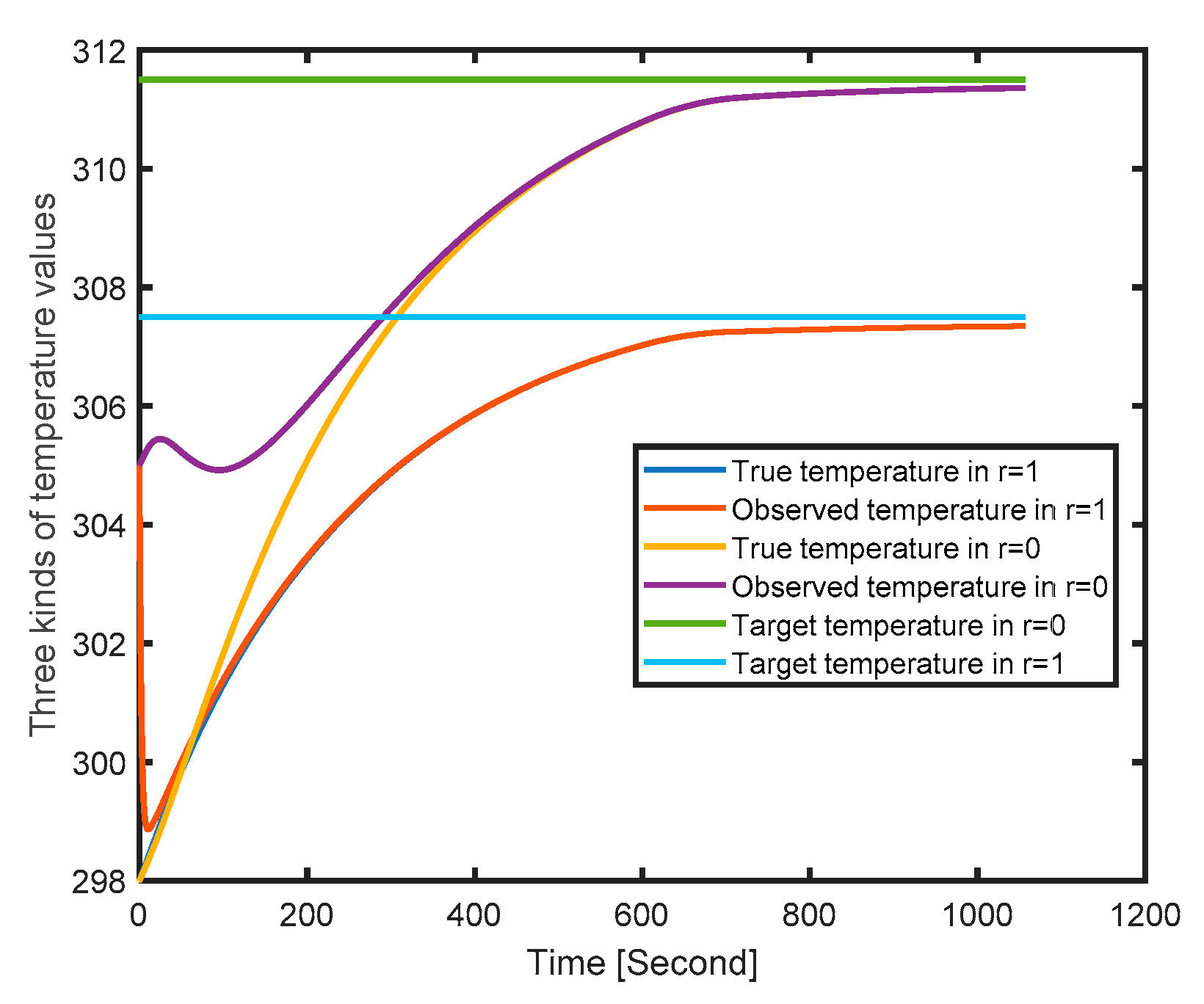
To verify the performance of the backstepping-based observer and controller, a constant current of 2 C is applied to a battery cell; the curve of the temperature rising is presented in
Figure 6.
and
represent the center and the surface of a battery cell, respectively. The two horizontal lines are the target temperature of the surface and the center of a battery cell. From
Figure 6, we can see that the temperature estimation of both the surface and the center is capable of tracking the true temperature and approaching the target temperature gradually. That is to say that we can control the temperature to a safe range using the proposed temperature controller.
5. Simulation and Results
In order to verify the performance of the proposed optimal fast-charging method, CC–CV, the most common pattern of fast charging, was used for the comparative study, including four aspects: charging time, maximum tangential stress, maximum radial stress, and film growth rate.
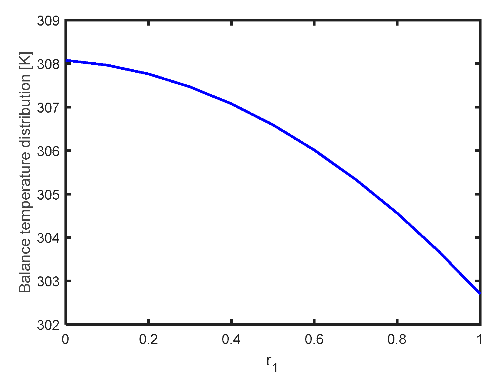
In the process of fast charging a lithium battery, the temperature of the battery cell grows quickly and the aging rate increases. To avoid overheating, the backstepping method is used to keep the battery cell at a constant temperature, as shown in
Figure 7. A constant temperature in the battery cell not only helps avoid overheating, but also helps compare the performance of the proposed fast-charging method with the CC–CV method. In order to find a compromise between the charging time and battery aging, the proposed optimal fast-charging method in this paper considers two aging factors: intercalation-induced stress and film growth. In the comparative study, the CC–CV pattern adopts three kinds of maximum charging current: 1 C, 2 C, and 3 C. This means that the effect of the choice of the maximum charging current on the comparative results is avoided.
In this paper, the upper limits of the radial and tangential stress are predetermined and optimal charging curves were obtained using the dynamic optimization approach. As we know, when charging occurs, the maximum tangential stress is located at the surface of the particle, and the maximum radial stress is located at the center of the particle. For an anode made of graphite, neither the maximum tangential stress nor the maximum radial stress is not allowed to exceed the yielding stress for any length of time to reduce the risk of anode fracture. The following case is discussed: charging a battery from 0% SoC to 100% SoC.
Figure 7 presents the balance of temperature distribution. If this balance is broken, the temperature controller would work to drag the temperature to the target position using various methods, such as changing the fluid temperature and adjusting the fluid flow velocity. Thus, a stable cell temperature can be achieved for safe operation.
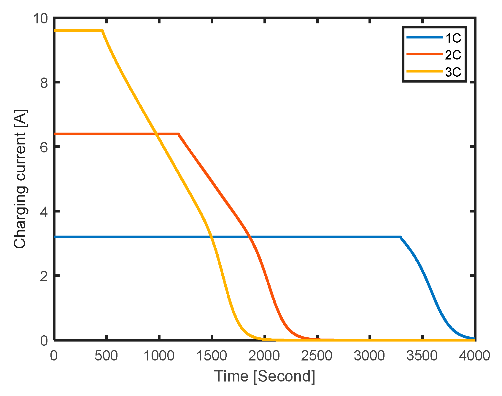
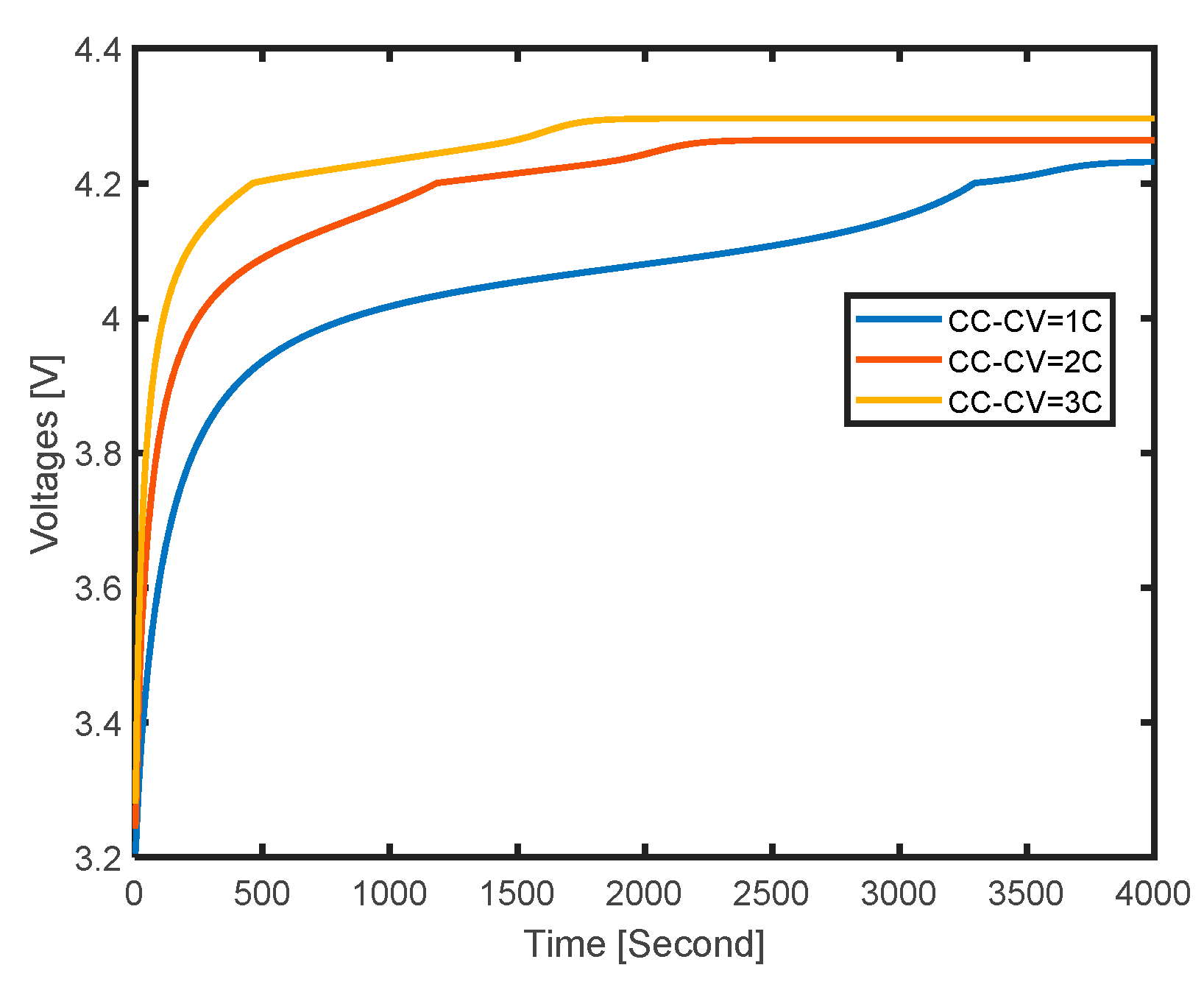
Figure 8 and
Figure 9 show the current and voltage curves of charging a battery from 0% SoC to 100% SoC by utilizing the CC–CV pattern under three maximum charging currents. At the initial charging stage, the input current maintains at the maximum and the terminal voltage climbs fast. When the output voltage reaches the upper value, this voltage is held until the battery cell is charged fully. With the increase in the maximum charging current, the time cost for full charging becomes less and less.
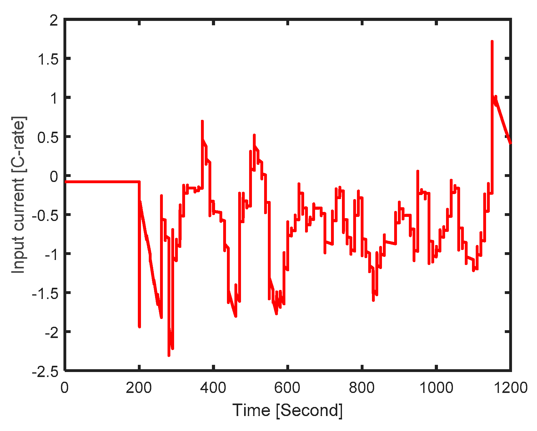
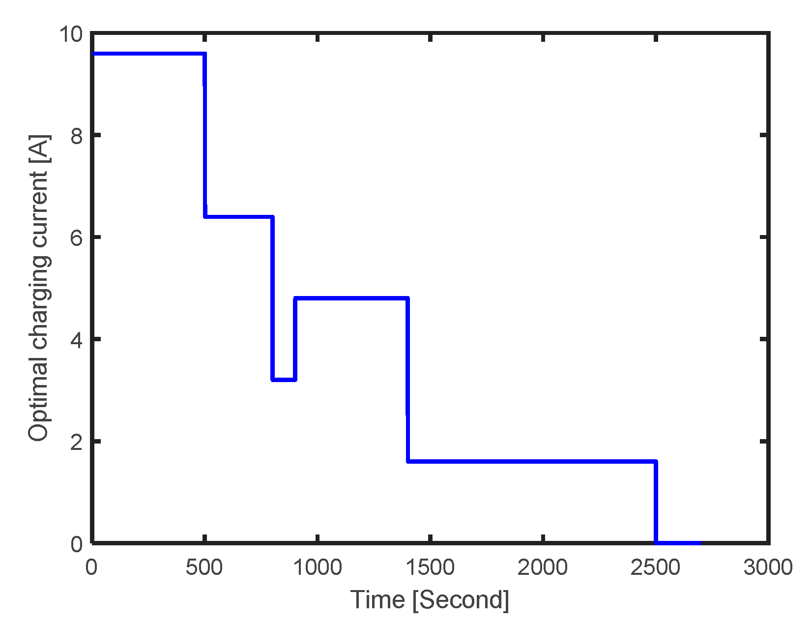
Figure 10 indicates the optimal charging current obtained by the dynamic optimization method. The upper value and lower values of the constraints are listed in
Table 1.
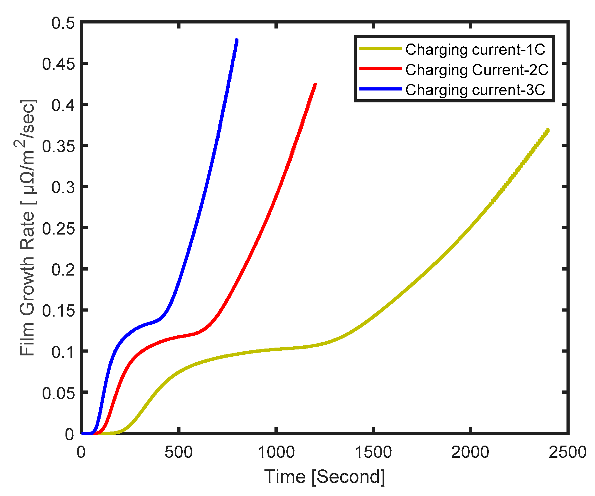
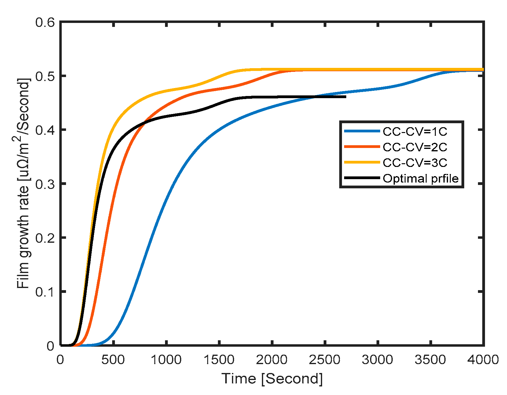
From
Figure 11, we see that the area under the film growth curve is smaller than those of the other three curves, which means the least lithium loss during full charging. At the same time, the charging time of the optimal charging profile just takes 200 s more than the time cost under CC–CV with a 3 C current, which is fast enough and acceptable.
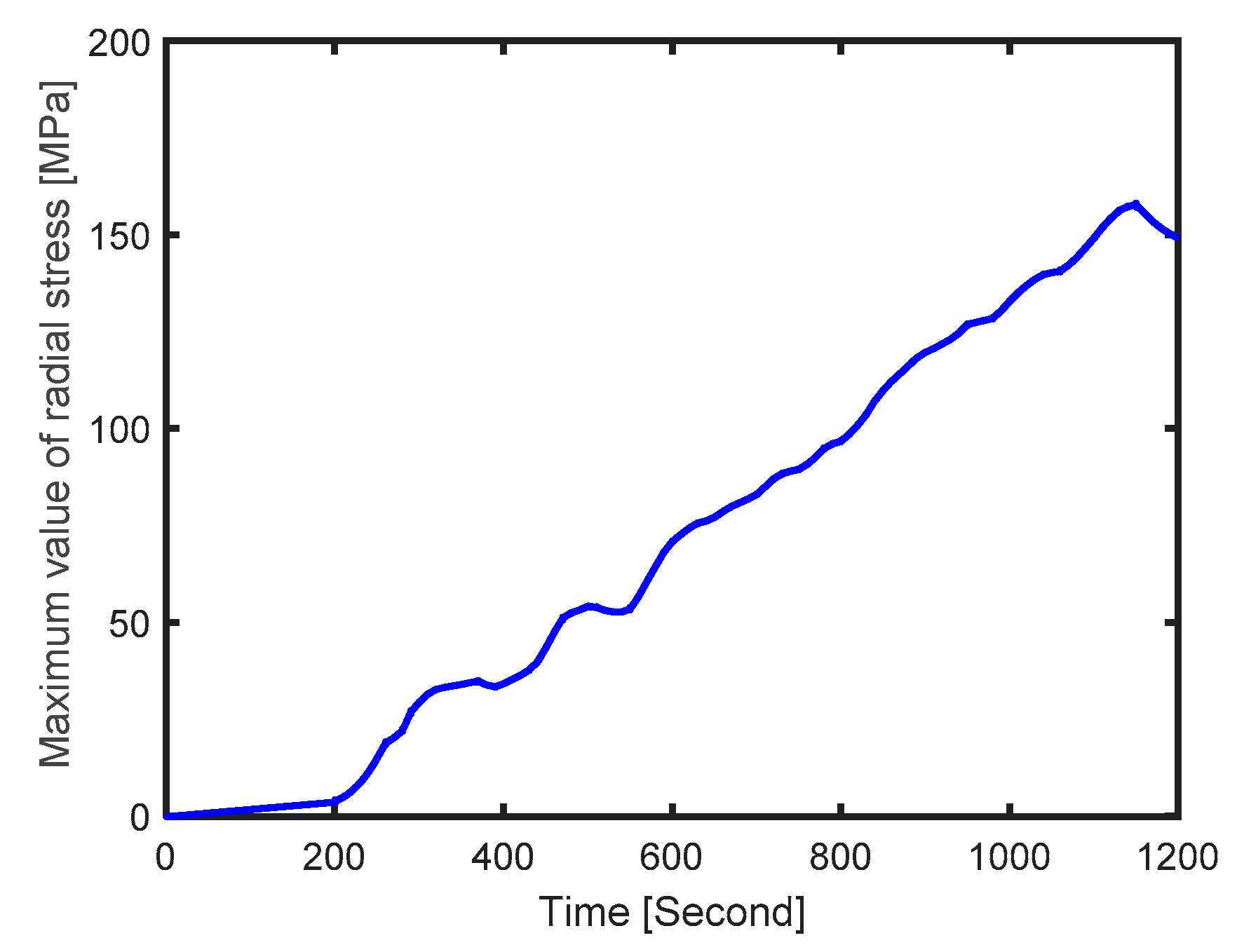
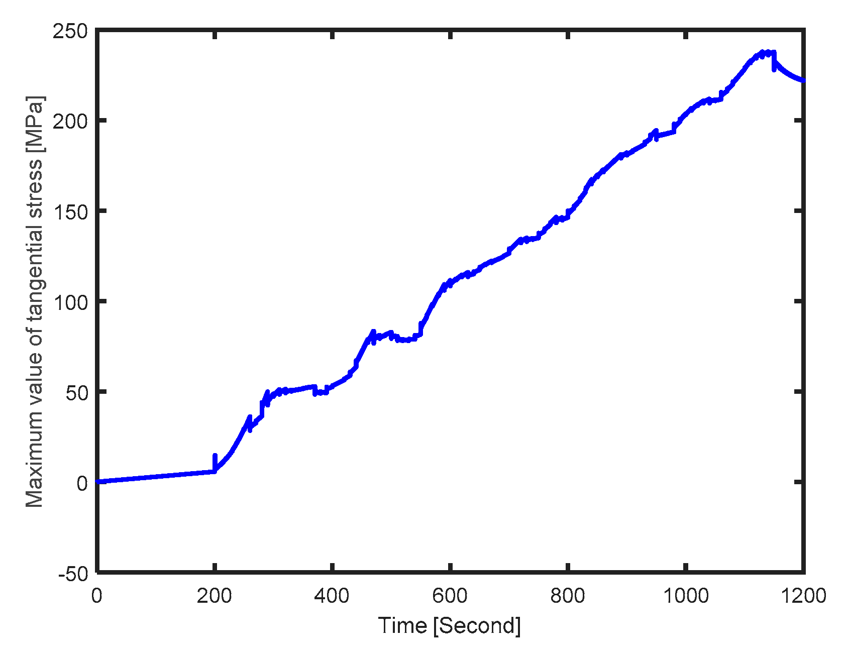
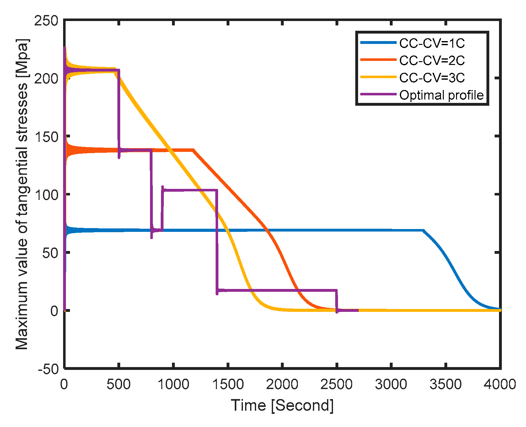
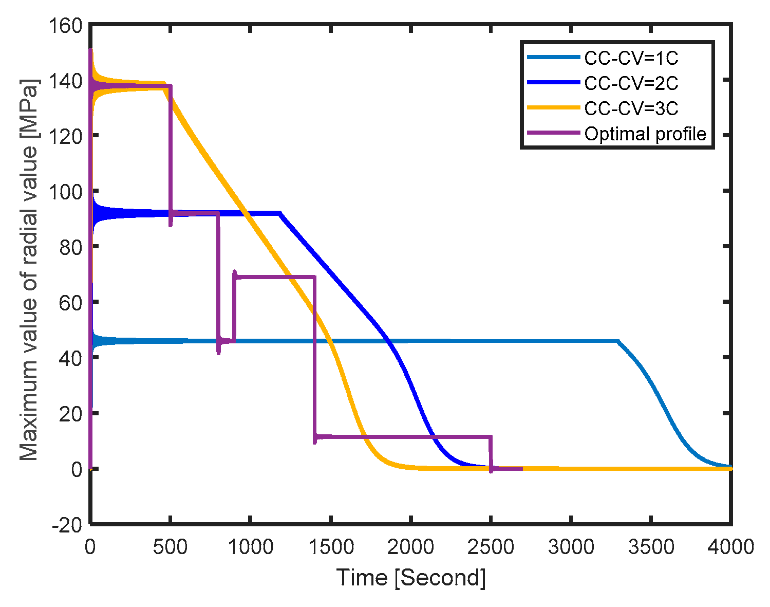
The yielding stress of the radial stress and tangential stress in a graphite-based anode are both around 30 MPa. If the radial stress or tangential stress is more than 30 Mpa for a long time, it is possible to cause fatigue failure and accelerate the aging process. From
Figure 12, the tangential stress generated by optimal charging profile becomes greater than its yielding stress within 1400 s, while the tangential stress under CC–CV with 1 C, 2 C, and 3 C is larger than 30 MPa for more than 1700 s, 2200 s, and 3700 s, respectively. From the maximum values of radial stress as shown in
Figure 13, we can see that the optimal charging profile causes a shorter period of overstress, which represents less electrode fatigue damage. Hence, the result shows that the optimal charging profile obtained by the dynamic optimization method has less probability of causing stress than the CC–CV profiles and so can slow the aging process and extend the battery life.
Therefore, while optimizing the charging speed, the proposed optimal charging method offers a good compromise between charging time and battery aging.
6. Conclusions
In this paper, the electrochemical–thermal model was employed to obtain the optimal charging profile and control the temperature of the cell. A temperature controller-based backstepping method was proposed to keep a relatively constant cell temperature to avoid overheating. Then, the effects of intercalation-induced stress were considered, because these cause particle fracture, which can accelerate the aging process. Furthermore, the growth of film on the surface of particles was also taken into account due to its ability to reduce the reused lithium ions. After that, the optimization objective was established, which minimizes the time cost during charging, while confining intercalation-induced stress and the growth rate of surficial film to a given range. Finally, the simulation was implemented and the results show that the film growth of the optimal charging curve is smaller than that of the other three charging curves, thus demonstrating the least lithium loss during full charging. Besides that, the tangential stress and the radial stress generated by the optimal charging profile were both greater than their yielding stresses for less time during charging as compared with the CC–CV pattern, which means there is less risk of electrode fatigue fracture. Furthermore, the charging time of the optimal charging profile just takes 200 s more than the time cost under CC–CV with a 3 C current, which is fast enough and acceptable. Hence, the proposed optimal charging method offers a good compromise between charging time and battery aging.


