Article

Modeling and Analysis of a Deflection Type Permanent Magnet Synchronous Wind Generator System

1
School of Artificial Intelligence, Hebei University of Technology, Tianjin 300130, China
2
School of Electrical Engineering, Hebei University of Science and Technology, Shijiazhuang 050018, China
3
School of Electrical Engineering, North China University of Science and Technology, Tangshan 063210, China
*
Authors to whom correspondence should be addressed.
Energies 2020, 13(6), 1524; https://doi.org/10.3390/en13061524
Submission received: 21 February 2020 / Revised: 18 March 2020 / Accepted: 23 March 2020 / Published: 24 March 2020
(This article belongs to the Special Issue Electric Machines and Drive Systems for Emerging Applications)

Abstract

:
A novel type of multi-degree-of-freedom (multi-DOF) deflecting-type permanent-magnet synchronous wind generator (PMSWG) is constructed to improve the reliability and utilization of wind energy. The basic working principle of the multi-DOF deflecting-type permanent-magnet synchronous generator (PMSG) is introduced, and its structural size is experimentally and theoretically determined. Subsequently, the multi-DOF deflecting-type PMSG was used to operate a complete wind turbine. A prototype and three-dimensional (3D) model of the wind turbine is simulated, allowing one to analyze the aerodynamics of the turbine and power generation performance. The electromagnetic field analysis is performed via analytical methods, followed by a 3D finite element and torque analyses. Furthermore, the wind turbine power generation characteristics curves are obtained through simulation software. Finally, transient analysis of post deflection is demonstrated. The before and after deflection values of the generator voltage, current, flux linkage, and induced voltage are compared and analyzed, relying on simulations and experiments. Additionally, the wind tunnel experiment is used to compare voltage variation with wind direction. The comparison reveals that the wind generator phase voltage remains maximized with wind direction variation. The results confirm that the proposed PMSWG has excellent performance and future research potential.

Graphical Abstract

1. Introduction

Wind energy is deemed a prospective energy source, owing to its clean and economic characteristics. The current target of the World Wind Energy Association is to generate 30% of worldwide electricity using wind power by 2025. The wind generator has thus become a common research subject [1,2,3]. Currently, most common wind power generators are squirrel cage asynchronous generators, permanent-magnet synchronous generators (PMSG), and doubly-fed asynchronous generators. The squirrel cage asynchronous generator wind turbine has low efficiency, as it cannot adjust the speed to obtain maximum wind energy. The gearbox therein increases the weight of the generator and reduces its efficiency. The electrical energy produced by a doubly-fed asynchronous generator is directly connected to a power grid through a boost transformer. Power electronic devices are used in the speed control system of generators to generate power harmonics. Moreover, the lagging reactive power from a grid must be absorbed, as it increases the power factor and burdens the grid. Therefore, reactive power compensation must be performed to improve the power factor. A PMSG avoids these limitations by removing the gearbox, causing the generator to drive the wind turbine blade directly. Although the PMSG has better efficiency than that of other generators mentioned above, it exhibits low utilization of wind energy. Therefore, building a new type of wind turbine generator which addresses this problem is necessary [4,5,6,7].
In [8], a doubly salient electromagnetic wind power generator is proposed. The salient structure in its rotor and stator is robust and straightforward. Moreover, its high efficiency, in cases involving considerable power, renders it particularly suitable for DC output and non-grid-connected wind power generation. However, its structure relies on the fixed-pitch stall regulated model, which reduces its efficiency because of wind fluctuations. In [9], a dual stator-winding induction generator was studied that could improve rotor speed stability. Simultaneously, a novel control-winding voltage-oriented drive method was proposed, which provides an additional supplementary control loop for adjusting the braking resistor, to ensure that the braking resistor absorbs all the kinetic energy of the generator and turbine. In [10], a novel passive maximum power point tracking (MPPT) is used in a wind turbine generator. Compared with the conventional MPPT, the novel structure does not use a DC/DC converter or any other electrical control device, making it highly reliable for outdoor use. Although this improvement promotes the reliability and use of the wind turbine generator, it does not focus on the generator. The active power response and grid frequency are decoupled in conventional synchronous generators; however, reference [11] proposed a virtual synchronous generator possessing active frequency regulation abilities; however, the study was only a theoretical project challenging to implement in practice. Reference [12] analyzed the outer rotor axial primary magnetic circuit permanent-magnet generator, which uses the outer rotor to achieve small size and direct coupling. The axial primary magnetic circuit can considerably improve the sensitivity gap, so that the key technology becomes easier to achieve. However, this model is only suitable for small-sized wind turbine generators.
A permanent-magnet rotor multi-degree-of-freedom (multi-DOF) generator can realize multi-DOF motion of the output shaft and considerably simplify the mechanical structure, while improving the response speed and positioning accuracy of transmission systems [13]. Therefore, the application of multi-DOF generators in the field of wind power generation has become a research topic receiving considerable attention. In [14,15], the magnetic field and modeling analysis of a multi-DOF deflection generator are proposed via analytical and finite element methods. The size of the permanent-magnet generator and material were determined via calculation. The rotor had a butterfly structure in [14], and the corresponding result shows that a butterfly-shaped permanent-magnet rotor multi-DOF generator can effectively enhance flux density and torque magnitude of the spin-rotation. In [16,17], rotor dynamics characteristics were analyzed, based on which, a mathematical model of the rotor under free state was established, and the results of the finite element and analytical methods were compared to verify whether rotor material rigidity affects the critical speed. Reference [18] shows the electromagnetic, thermal, and solid fields of the multi-DOF permanent-magnet motor, together with a multiphysics coupling analysis of the motor. The temperature increase and stress–strain of the designed structure were obtained via a simulation of the magnetic–thermal–solid coupling, considering the electromagnetic structure as the research object.
Most previous research has only considered the generator ontology analysis, and only a few studies have used a multi-DOF motor as the wind turbine generator. In [19], a multi-objective multi-DOF optimization control method using the model predictive approach was introduced. The control system therein exhibited excellent dynamic performance. Moreover, generator power fluctuations and drive train transient loads were both reduced. However, the control model was linear; thus, the accuracy of the system decreased due to wind fluctuation. Reference [20] focused on a multi-DOF ultrasonic motor using the in-plane deformation of P b ( Zr x Ti 1 x ) O 3 (PZT) elements, presenting its working principle, and driving circuit requirements. However, only the basic structure and working principle of the motor were considered, neglecting its magnetic characteristics.
According to the literature review, few research studies have used a multi-DOF generator as a wind turbine generator. Hence, the present study introduces a multi-DOF deflecting-type permanent-magnet synchronous wind generator (PMSWG). The contributions of this study can be summarized as follows:
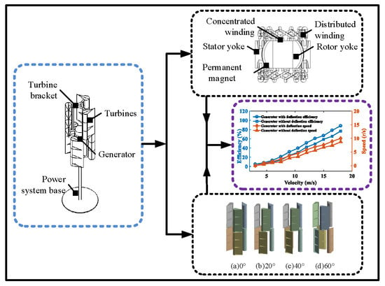
  • A novel multi-DOF deflecting-type PMSG is constructed.
  • The basic characteristics of the PMSG, including the structure, mechanism, electromagnetic field modeling, and torque analysis, are developed and analyzed
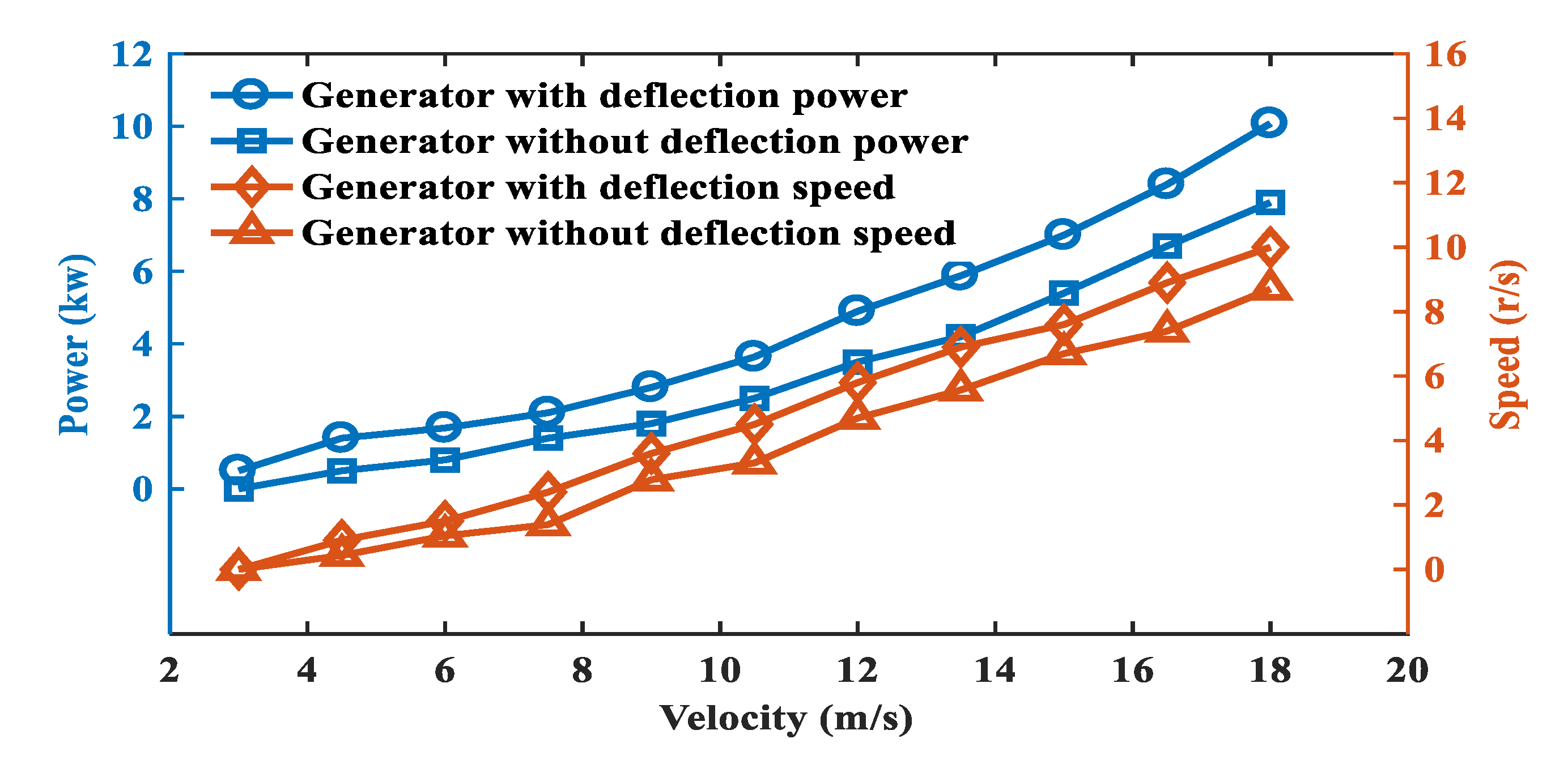
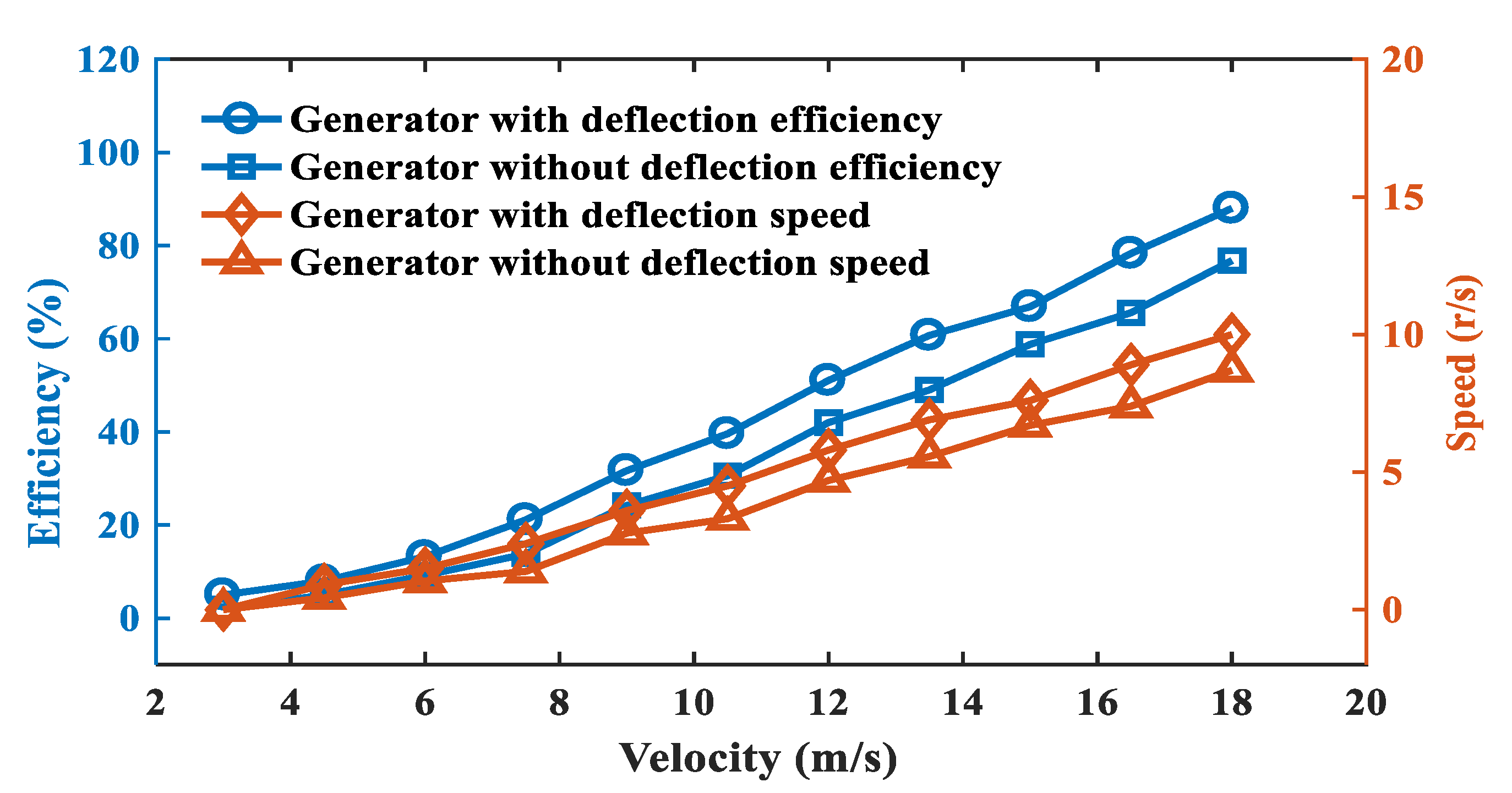
  • The PMSG is used to operate a complete wind turbine, and the resulting aerodynamics and power generation performance of the wind turbine is analyzed.
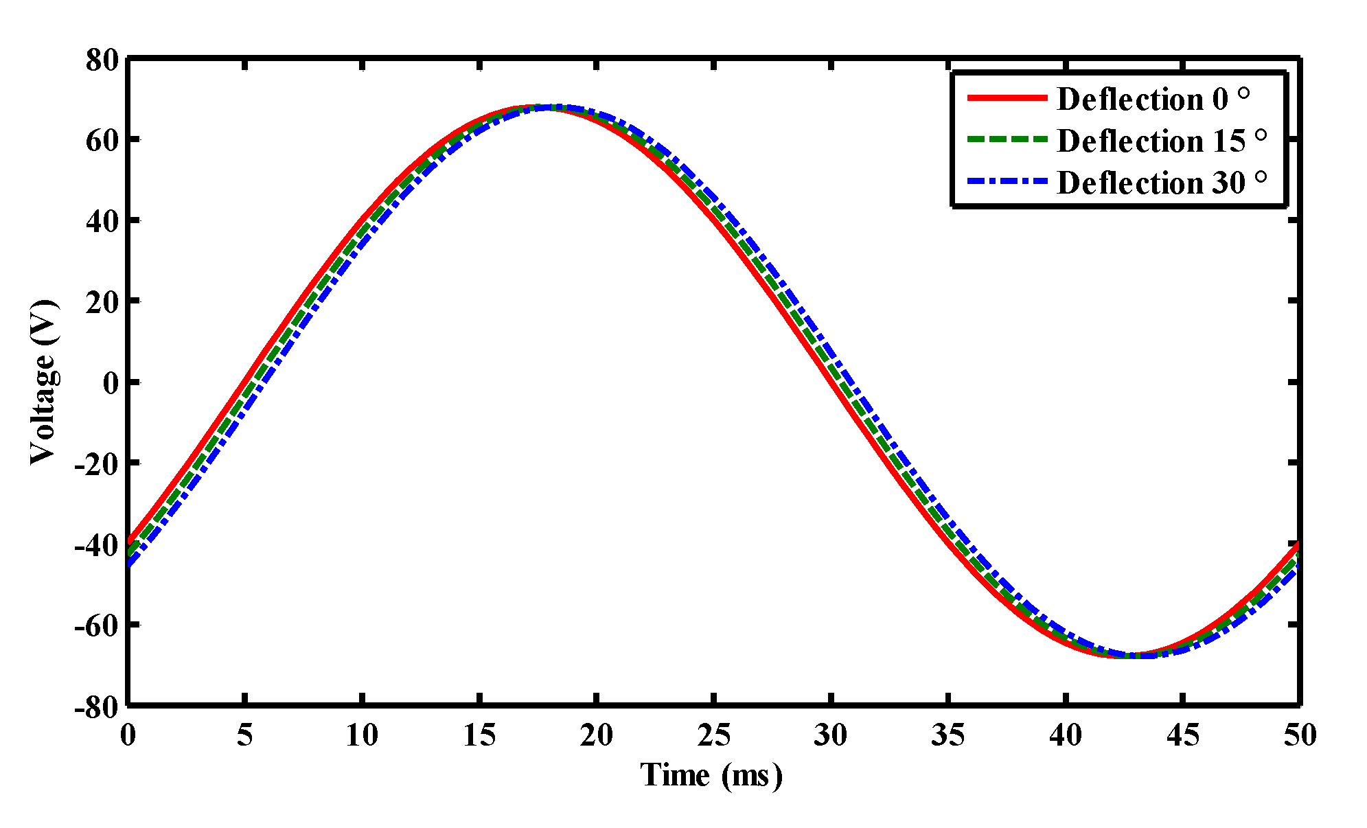
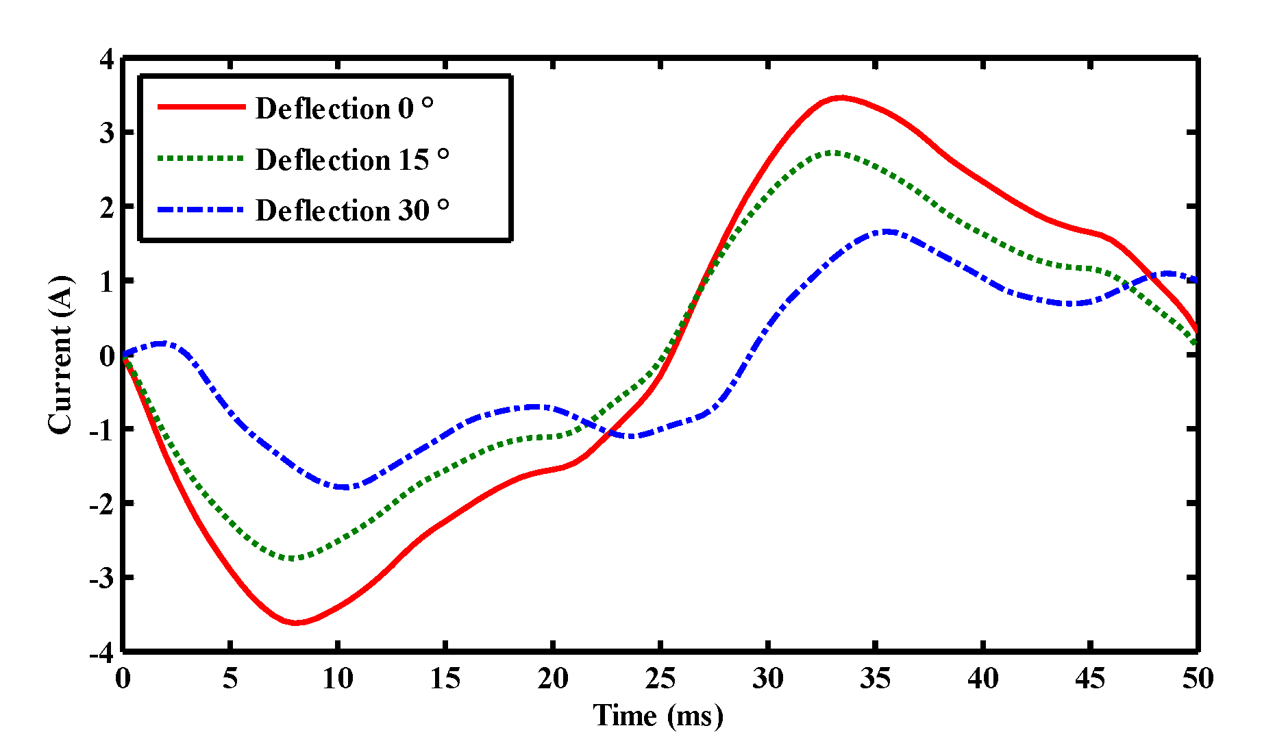
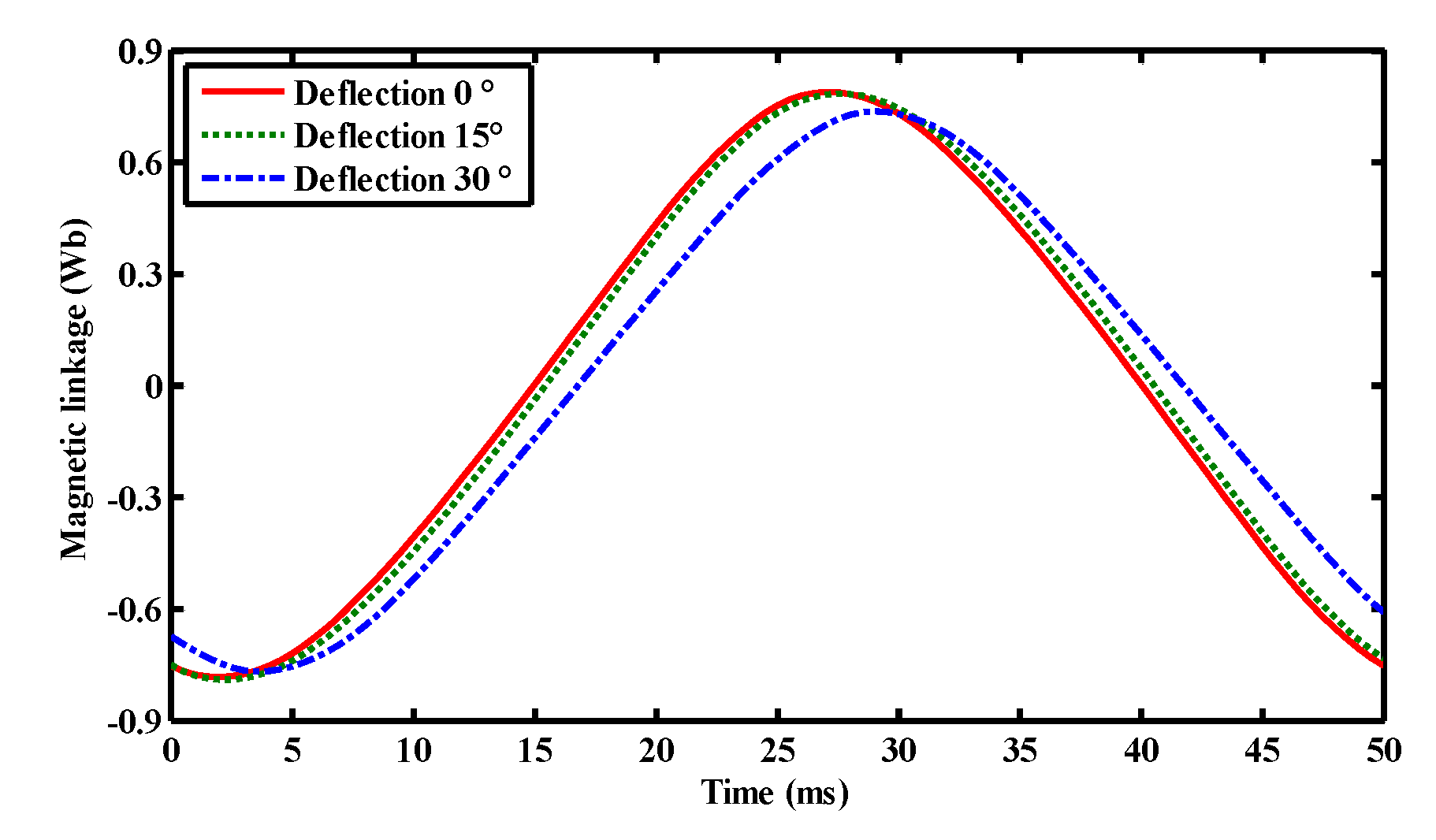
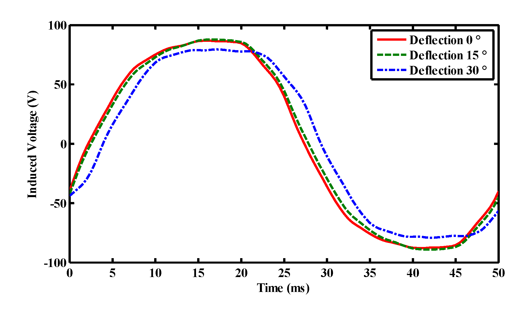
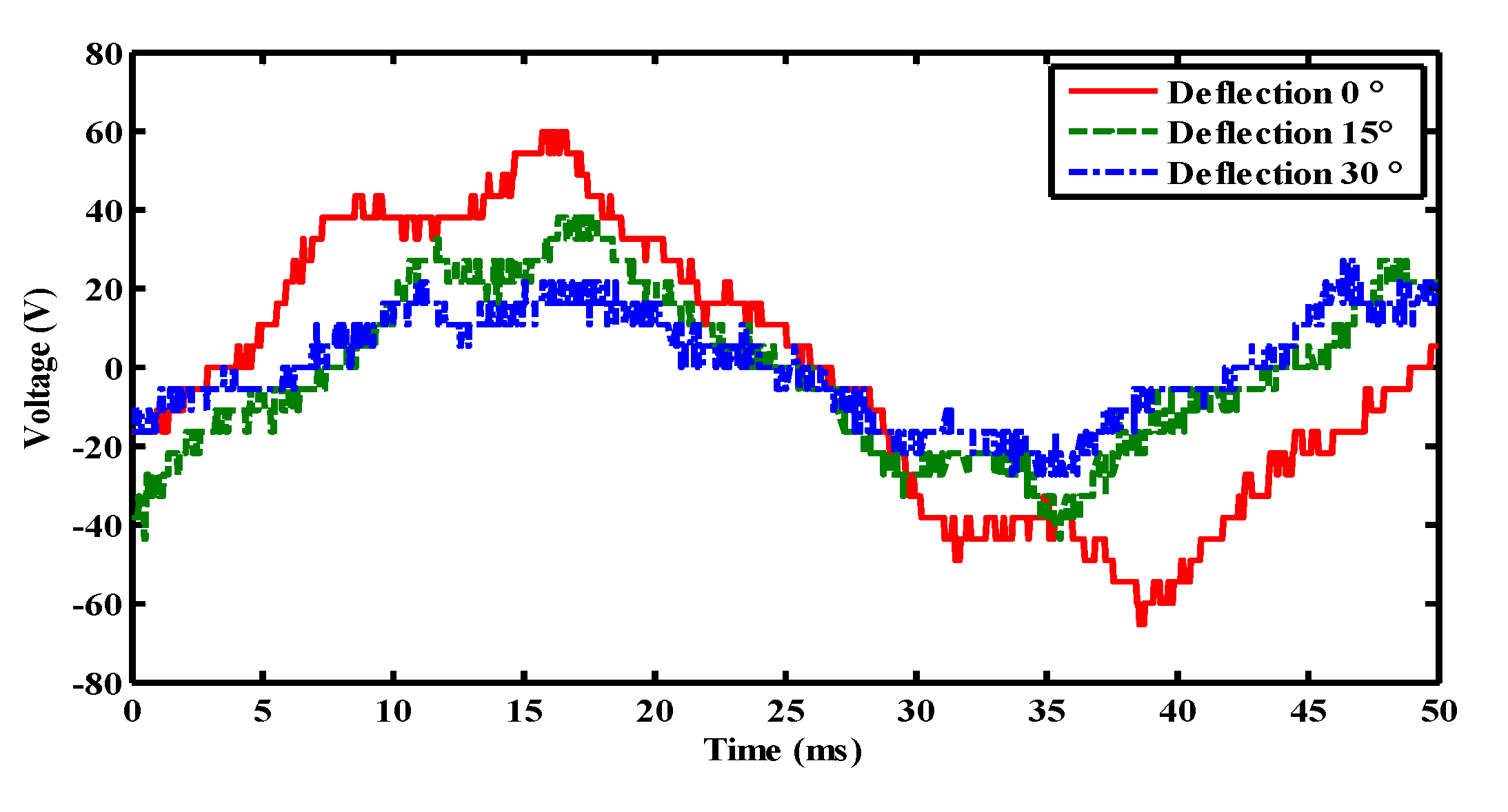
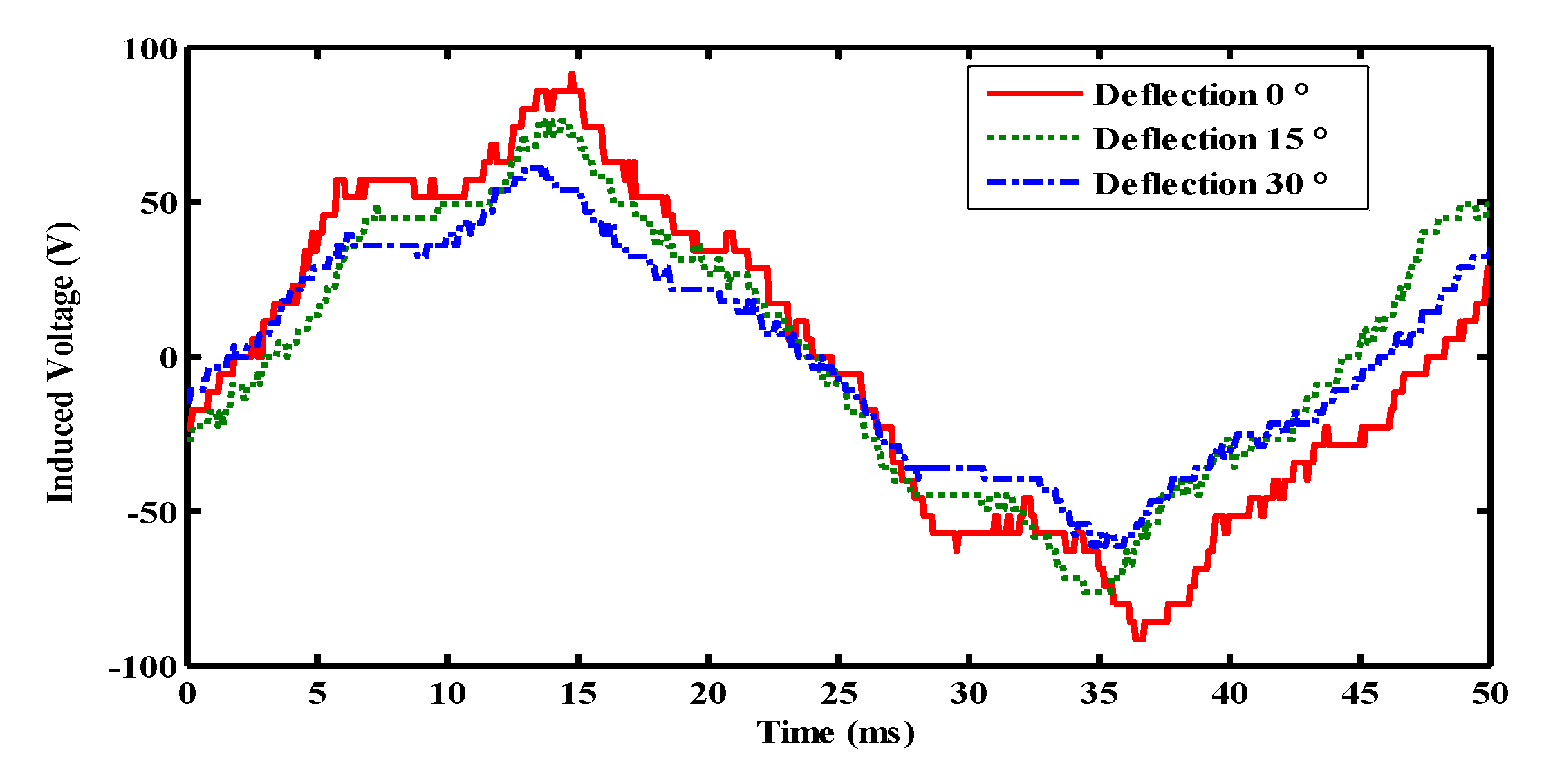
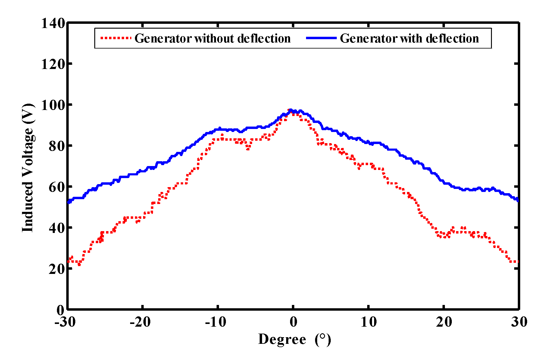
  • The generator’s operation characteristics before and after deflection are compared, and voltage variation with wind direction is demonstrated.
In Section 2, basic structural parameters and the mechanism of the generator are addressed. Section 3 presents electromagnetic field modeling via both the analytical method and three-dimensional (3D) finite element analysis. Simultaneously, both rotation and deflection torques are analyzed. Section 4 illustrates the operation of the generator as a wind turbine, and an investigation of its aerodynamics and power generation performances. Section 5 presents simulations and experimental evaluations. Finally, the discussion and concluding remarks are presented in Section 6 and Section 7, respectively.

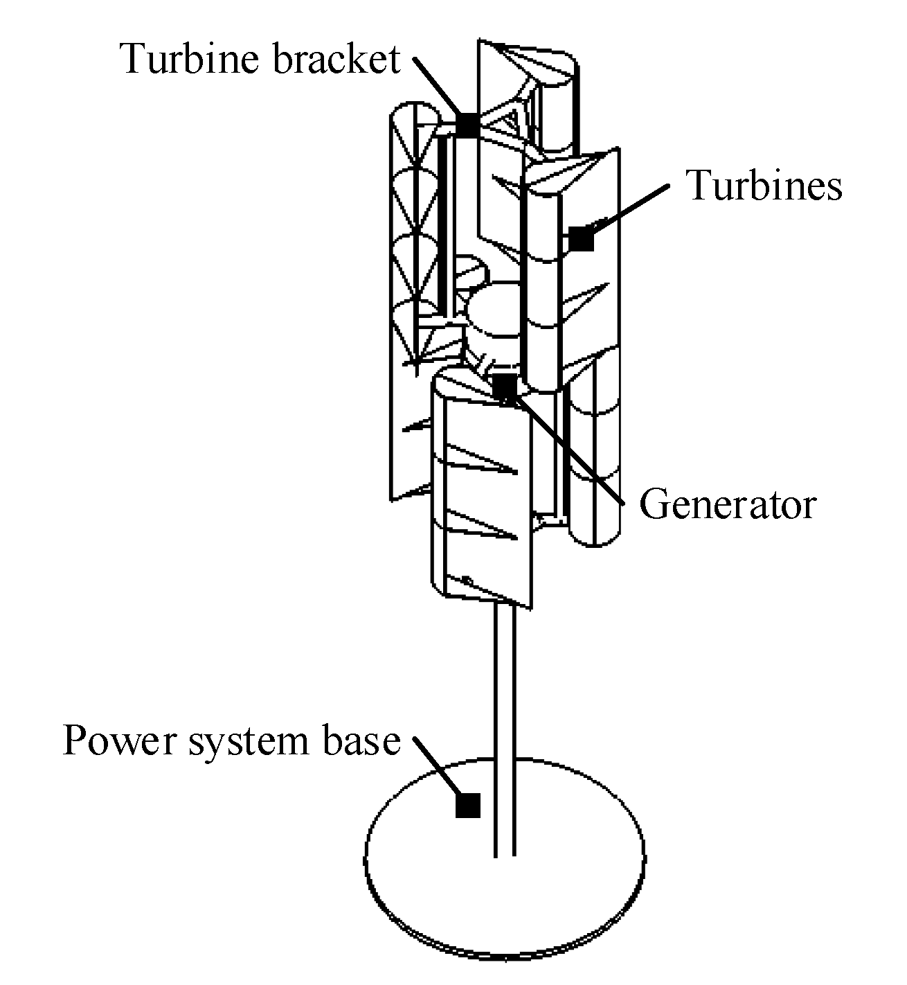
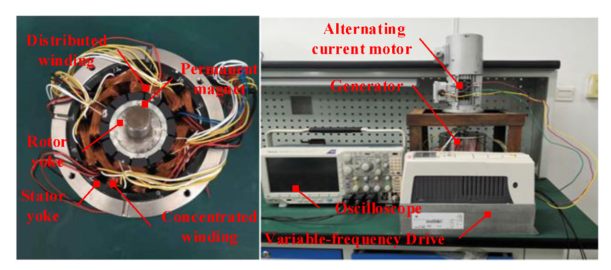
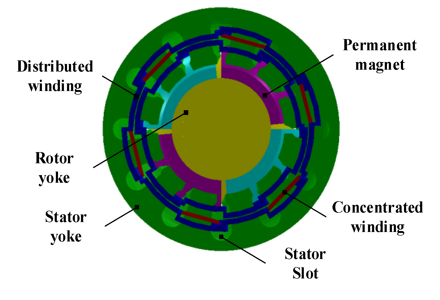
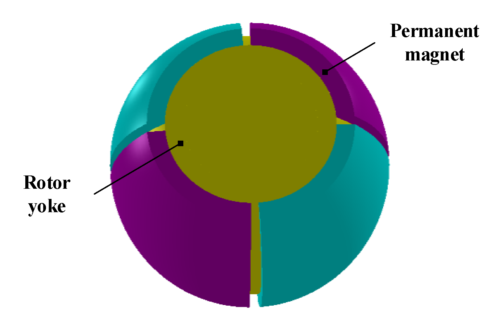
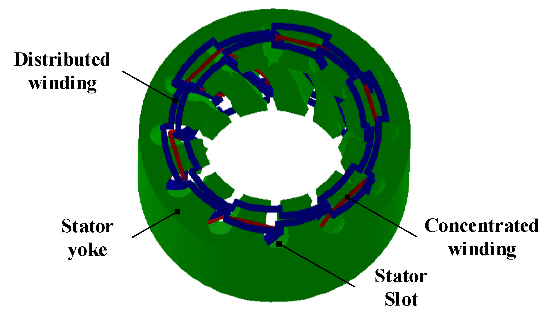
2. Structural Parameters and Mechanism of Multi-DOF Deflecting-Type PMSWG

A wind generator is one of the core components of a wind turbine. Traditional wind generators focus on a single wind direction, and wind energy efficiency substantially reduces when the wind direction changes. A deflecting-type PMSWG performs wind wheel deflection through a control system, which can align the wheel according to the wind direction and increase the rotation speed of the wheel. This control strategy can increase the wind energy use rate of the wind turbine, by performing rotation with multiple degrees of freedom; thus, the turbine not only rotates, but also deflects to a certain angle. Moreover, the wind turbine is directly connected to the generator, saving materials, and simplifying the structure of the turbine. In addition to the advantages of a simple structure, high power generation efficiency, and small size, the proposed novel wind generator exhibits large output torque, simple control structure, and stable power generation.

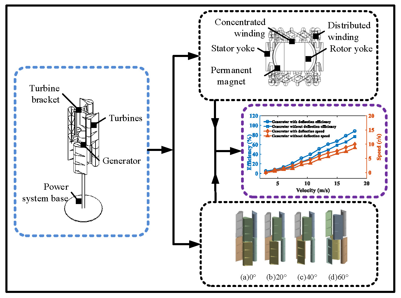
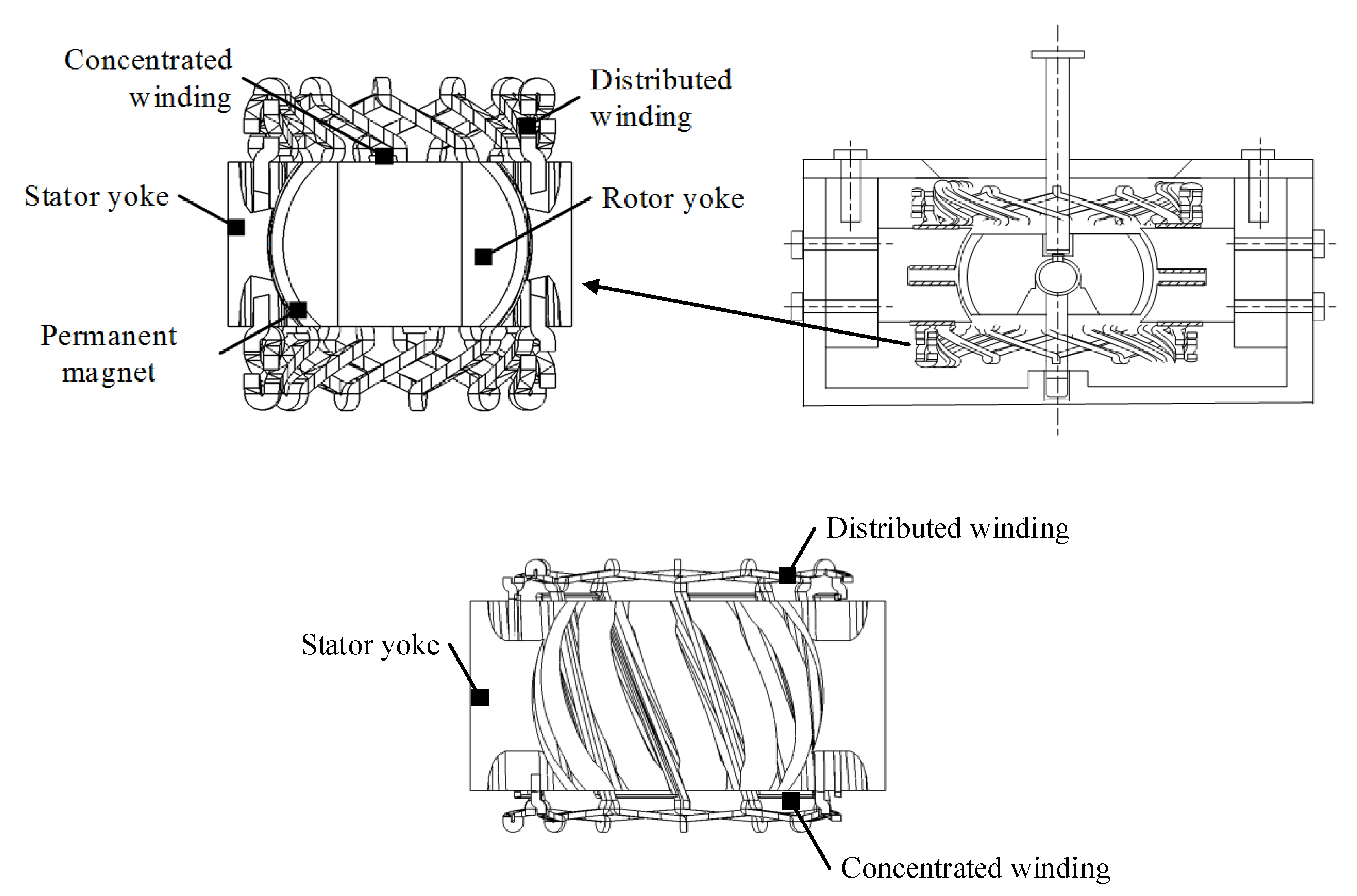
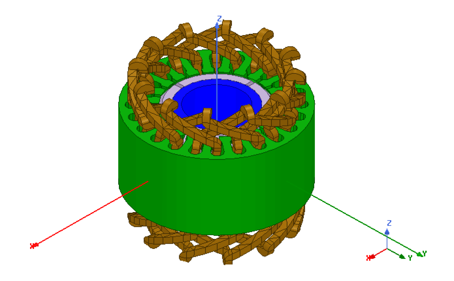
2.1. Generator Structure

The deflecting-type PMSG comprises a stator, a rotor, and windings. The inner core of the rotor contains a magnetic conductive material and a magnetic separator, comprising a non-magnetic conductive material, having the separator placed outside the inner core. The permanent magnets are arranged along the output radial direction between two adjacent magnetic separators that form staggered distributions of the North (N) and South (S) poles. The permanent magnets are sintered from NdFeB material with radial magnetization and a spherical shape, whereas the stator is cylindrical with two types of windings. The stator is made of M19-24G_2DSF0.950 material, and the manufacturing technique is almost the same as traditional PMSG. The distributed winding can operate the generator in a generating state, which is embedded in the pear-shaped groove, creating convenient embedding lines for heat dissipation and a high utility rate, with no insulation layer between the windings. The other type, concentrated winding, is evenly and symmetrically distributed on both sides of the generator middle plane, enabling the generator to operate in an electric state. The stator magnetic yoke composed of magnetic material comprises evenly divided stator pole boots with stator slots between them. The concentrated windings are placed on the stator pole boots. When the generator is used in the electric state, the concentrated windings conduct external power supply and deflect the rotor. Figure 1 shows the basic structural diagram of the generator.

2.2. Determination of Main Parameters

The designed wind generator is suitable for small power applications, owing to its simple structure and installation. The proposed generator can also perform grid-connected operations. The generator uses a battery to store electricity; hence, it requires several batteries to obtain a high rated output voltage. The output voltage selected herein is not significantly high to reduce the cost of the complete machine. Specifically, the designed generator has low voltage and high current, with the rated power and rated voltage set to 10 kW and 120 V, respectively.
According to wind speed variability, the generator is required to work in a wide range. Moreover, as no gearbox mechanism is used, the shaft is directly connected to the wind wheel coupling. Thus, the speed of the generator directly depends on the wind speed, and the generator must have a low rated speed. The starting wind speed of the generator is 2.5–3 m/s, while the operating wind speed range is 2.5–18 m/s, and the rated speed of the generator is set at 600 r/min.
Compared with other permanent magnet materials, the NdFeB has a strong anti-demagnetization ability and excellent magnetic properties, which is more suitable for use in small and medium-sized permanent-magnet wind turbines. Considering both experimental requirements as well as an economical and easy-to-assemble principle, we proposed a four-pole generator model rather than a multi-pole model (more than four poles). Table 1 lists the parameters of the generator.

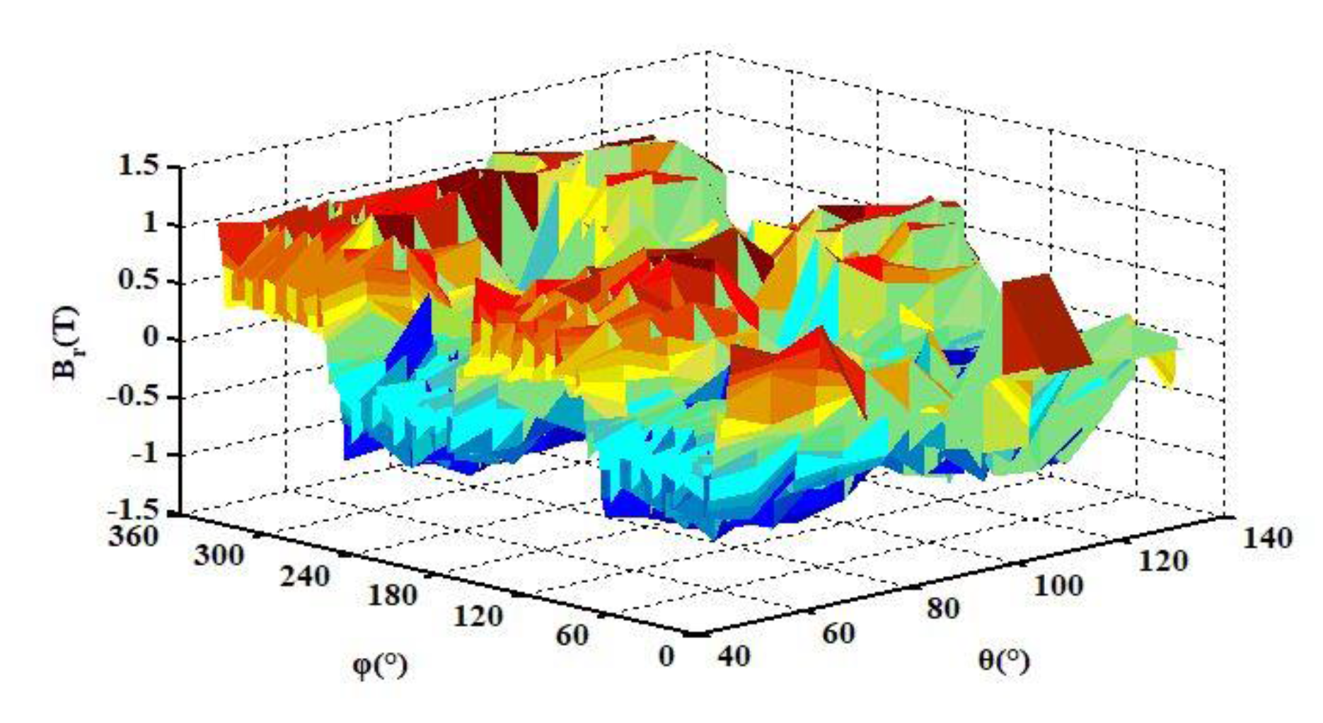
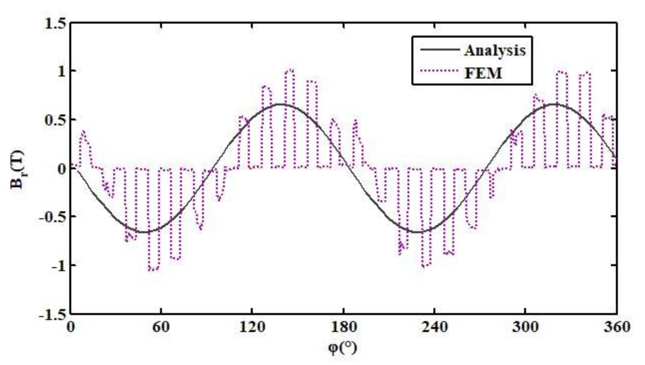
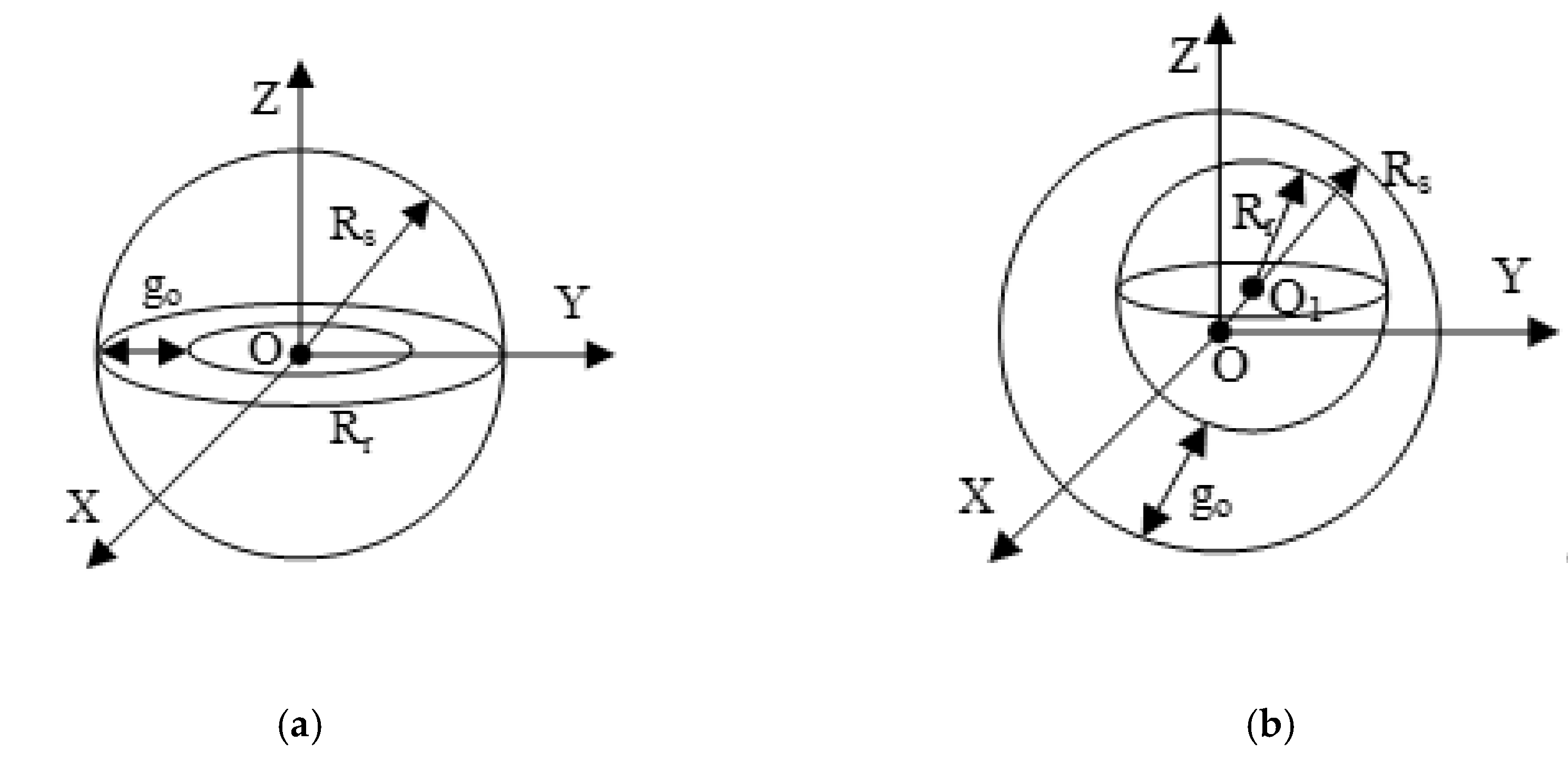
3. Electromagnetic Field Modeling and Torque Analysis

The magnetic field characteristics of a generator are crucial in generator analysis. The proposed generator’s magnetic field model is established through the analytical method and finite element analysis. Moreover, the accuracy of the results of the two modeling methods is compared [21,22,23].

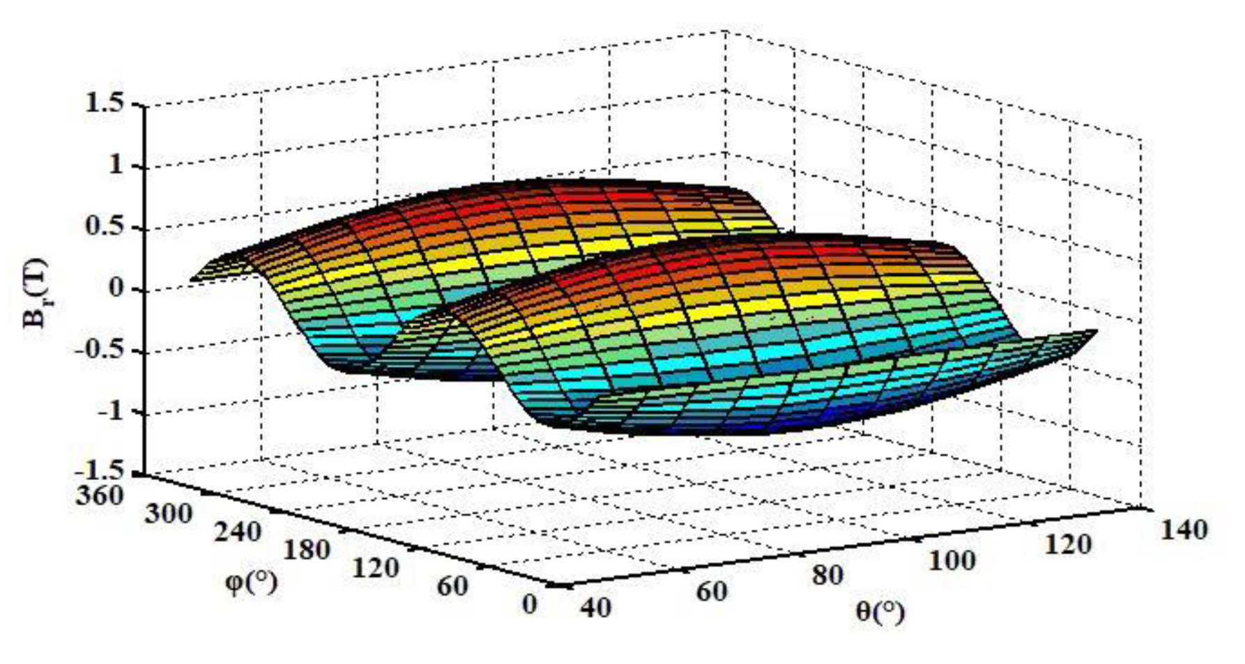
3.1. Analytical Method Modeling

According to the boundary conditions of magnetic media in different regions of the rotor space, the rotor can be divided into three regions, as shown in Figure 2. This is in the region between the rotor permanent magnet and stator winding, termed as Region 1, where both interact with each other to form an air gap magnetic field. The rotor permanent magnet forms Region 2, whereas the inside of the rotor permanent magnet is termed Region 3.
The magnetization characteristic in the three regions is given as follows:
B 1 = μ 0 H 1   ,
B 2 = μ 0 μ r H 2 + μ 0 M 0   ,
B 3 = μ 0 μ r H 3 .
where B 1 , B 2 ,   and   B 3   are the magnetic induction intensity in region 1, 2, and 3, respectively, H 1 ,   H 2   and   H 3   are the magnetic field intensities in region 1, 2, and 3, respectively, and μ 0   and   μ r   are   the permeability of vacuum and relative permeability of the permanent magnet, respectively, and M 0 is the residual magnetization.
No current flows through any of the three spatial regions of the rotor; hence, the magnetic fields in all three regions satisfy the following equations:
×   H k = 0 ,   k   = 1 , 2 , 3 ,   and
·   B k = 0 ,   k   = 1 , 2 , 3 .
The relationship between the magnetic field density and scalar magnetic potential is H k = Φ k ; in spherical coordinates, this relation can be expressed as:
H   = H r e r + H θ e θ +   H φ e φ = Φ r e r 1 r   Φ θ e θ 1 r   sin θ   Φ φ e φ .
The Laplace equation for a scalar magnetic potential in spherical coordinates is given as follows:
1 r 2 [ r ( r 2 Φ k ) + 1 sin θ θ ( sin θ Φ k θ ) + 1 sin 2 θ   Φ k φ ] = 0 .
Therefore, the general solution is:
Φ ( r , θ , φ ) = l = 0 + m = l l ( A l m r l + B l m r l + 1 ) Y l m ( θ , φ ) ,
where Y l m ( θ , φ ) denotes the spherical harmonic function, P l m ( cos θ ) is the associated Legendre function, and A l m and   B l m are unknown coefficients.
According to the existing condition of the three regions, the boundary conditions of the motor are set as follows.
At infinity outside the rotor (r = ∞), the magnetic induction intensity is 0. That is:
B 1 r | r = = 0 ,   B 1 θ | r = = 0 ,   B 1 φ | r = = 0 .
At the boundary between the air-gap region and the permanent magnet radius (r = R r ), as well as at the boundary between the rotor core and the permanent magnet body radius (r = R b ), the tangential components of the magnetic field and magnetic induction intensities are continuous. That is:
B 1 r | r = R r = B 2 r | r = R r ,   H 1 θ | r = R r = H 2 θ | r = R r ,   H 1 φ | r = R r = H 2 φ | r = R r
  B 3 r | r = R r = B 2 r | r = R r ,   H 3 θ | r = R r = H 2 θ | r = R r ,   H 3 φ | r = R r = H 2 φ | r = R r .
At the rotor core (r = 0), the magnetic induction intensity is finite:
B 3 r | r = 0 ,   B 3 θ | r = 0 ,   B 3 φ | r = 0 .
Thus, the expression of the air-gap flux density of a permanent magnet can be expressed as follows:
{ B 1 r = l = 0 m = l l ( ( l + 1 ) μ B l m 1 r l + 2 ) Y l m ( θ , φ ) B 1 θ = l = 0 m = l l ( μ B l m 1 r l + 2 ) Y l m ( θ , φ ) θ B 1 φ = l = 0 m = l l ( μ B l m 1 r l + 2 ) 1 sin θ Y l m ( θ , φ ) φ .
As the generator is radially magnetizing, we exclusively focus on the analysis of B r . Moreover, if we exclusively consider the fundamental wave, the air-gap component B r changes in the direction of φ with the sinusoidal wave. Figure 3 shows the B r plot, wherein two positive and negative peaks are observed across the equator, which agrees with the structure of the four-rotor magnetic poles. When θ = 90 ° , the air-gap magnetic density is the largest; thus, the closer the position is to the equator of the rotor magnetic pole, the greater the magnetic density. The amplitude of B r is approximately 0.5 T.

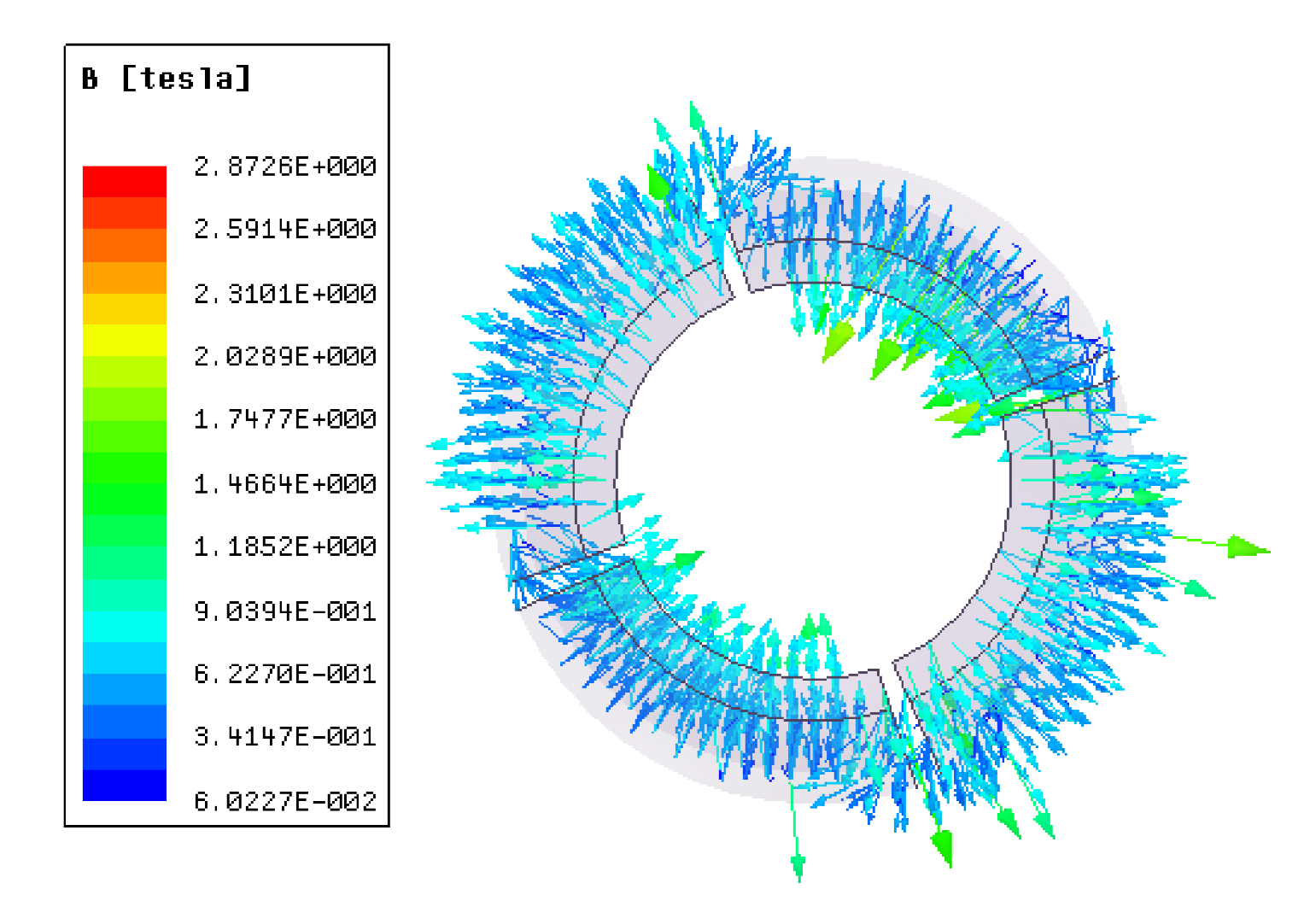
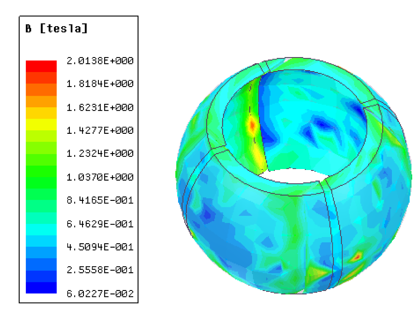
3.2. Finite Element Analysis Modeling

The analytical method can only calculate fundamental wave components of the magnetic field under ideal conditions, ignoring many unimportant conditions. Therefore, Finite Element Analysis (FEA) software was used to model and analyze the magnetic field more accurately.
The finite element model of the generator was established, and the material properties, boundary conditions, and excitation sources of the model were set. The specific simulation parameters are shown in Table 2. Figure 4 presents the finite element solution model of the generator.
The model parameters, which include the number of iteration steps calculated, were set. Additionally, the convergence error value was solved, and the percentage of units was updated at each iteration. Finally, a static simulation of the generator was performed. Based on an adaptive solution, the system error was small, and the target requirement could be achieved. Figure 5 and Figure 6 show the magnetic density curve of the generator and the magnetic dense cloud plot of the rotor.
According to Figure 7, the air-gap component B r changes in the direction of φ with the sinusoidal wave; Figure 7 is nearly identical to Figure 3, obtained through the analytical method.
Figure 8 compares the air-gap magnetic flux obtained using the finite element and analytical methods when θ   =   90 ° . Based on Figure 8, the variation trend of air-gap magnetic flux is nearly identical for both methods, and the amplitudes are similar. The curve appears smooth because the analytical method neglects some factors, having less impact on the model. The finite element model simulates the change in the air-gap magnetic field under regular motor operation; thus, several harmonics exist in time and space. Consequently, the curve of the finite element method appears to be more irregular.

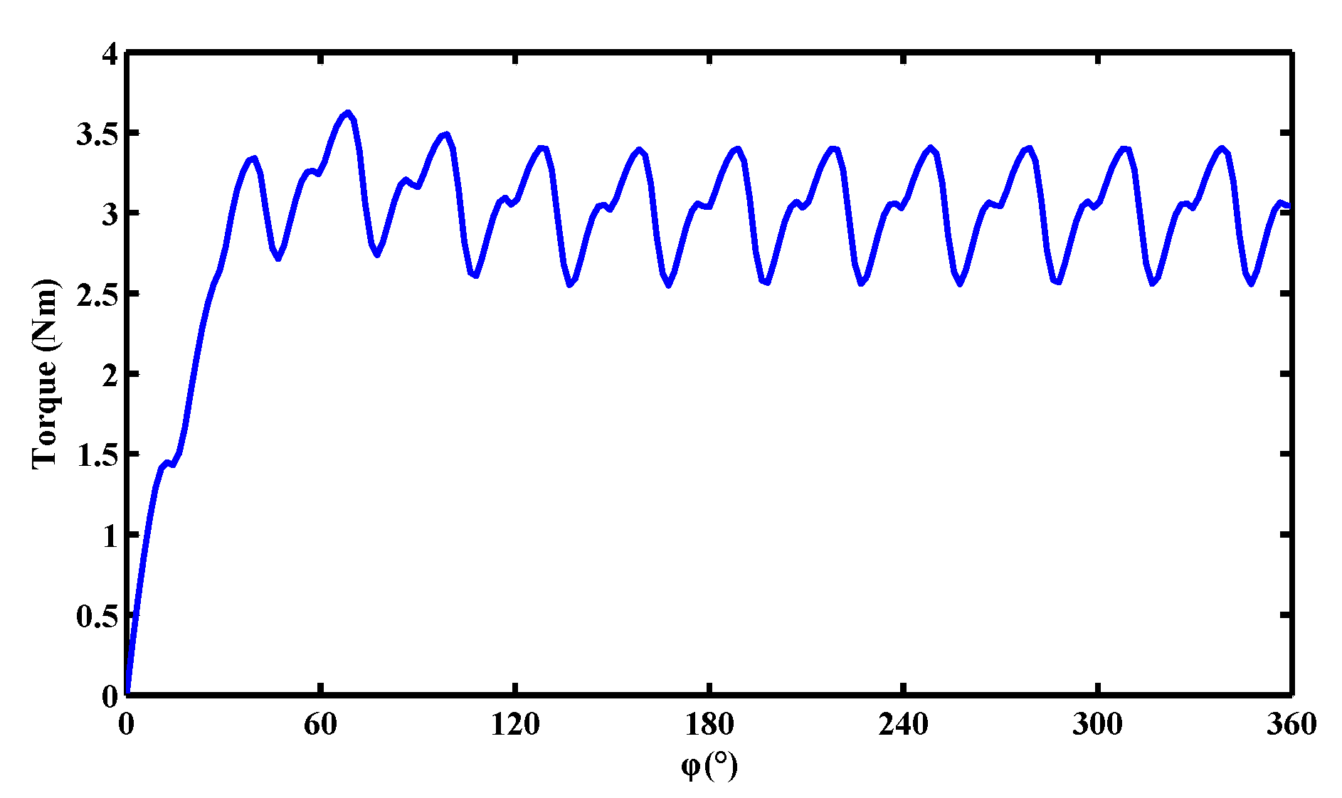
3.3. Torque Analysis

3.3.1. Rotation Torque

The torque calculation considers the flux linkage before and after virtual displacement as constant, while the system is considered free of loss. Thus, the formula for estimating the total energy stored in the solution domain is given as:
W = 0 B H · dBdV ,
where V denotes the volume of the field, and H represents the magnetic field intensity.
According to the virtual displacement principle, the rotor is assumed to have a small angular displacement φ along the equator. Thus, the torque in the direction receiving φ by the rotor is:
T φ = W φ
where the electromagnetic torque T φ is the rotation torque along the equator.
Figure 9 shows the rotation torque of the generator, which is approximately symmetric and changes periodically.

3.3.2. Deflection Torque

The controller can control the generator to change the operation state if deflection is required. Through a brief adjustment, the generator operates in the electric state. At this time, the energy storage power supply is used to drive the generator to deflect, the wind wheel is aligned with the wind direction, and the controller ensures that the generator operates in the generating state. Further, the working principle is the same when the generator operates in the electric state. That is, it follows a similar principle as that of the permanent-magnet deflection-type motor, in which both working modes rely on the interaction between the magnetic fields generated by the current coil and the permanent magnet. A current is fed to several coils to generate N-pole magnetic fields to enable deflection. Conversely, an opposite current is applied to several other coils, which consequently generate S-pole magnetic fields. Following the principle of like poles repel and unlike poles attract, the generated N- and S-poles are repulsed and attracted. Table 3 lists the values of deflection torques at different angles. Based on these tables, when the deflection angle increases, the distance between the rotor and the stator increases, which causes a decrease in the deflection torque.

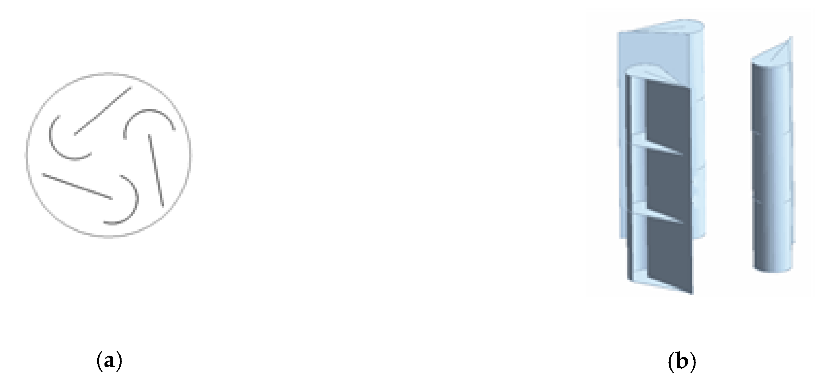
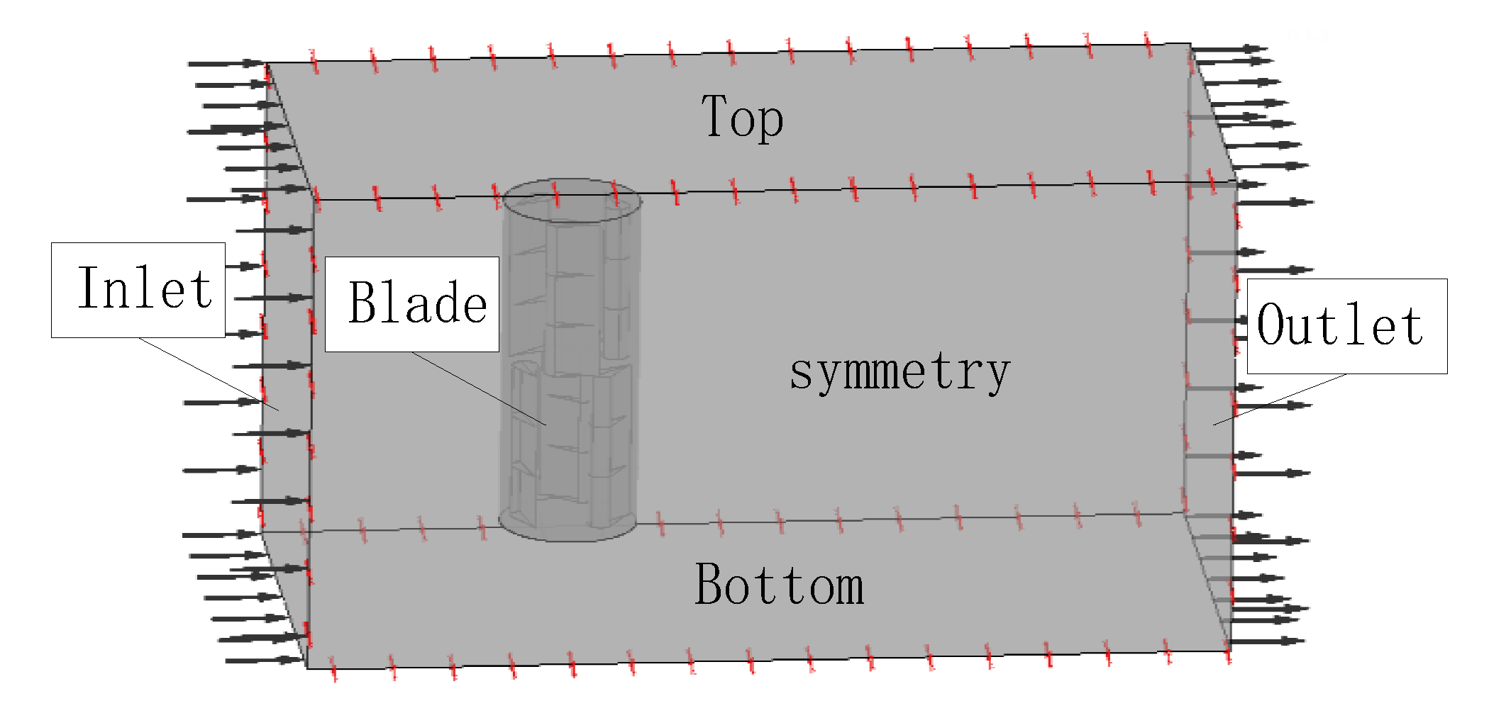
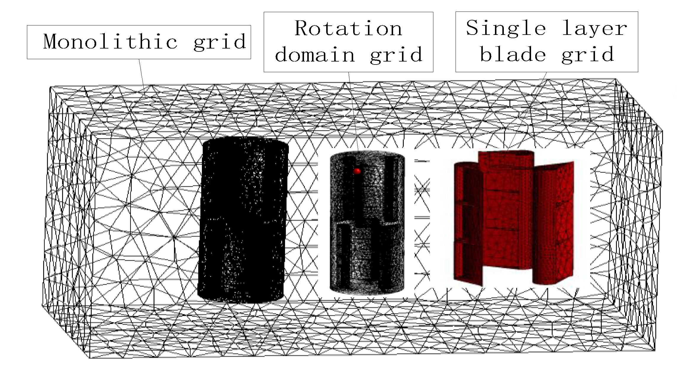
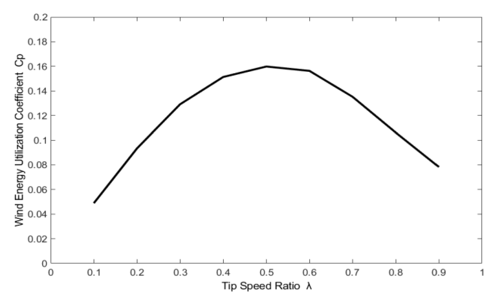
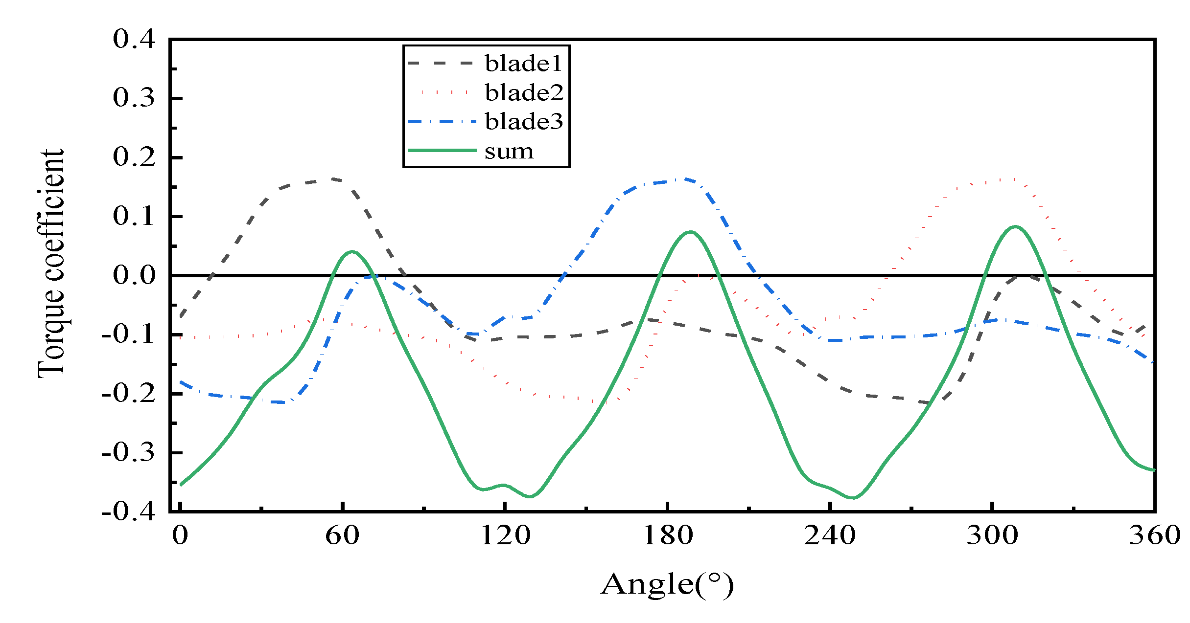
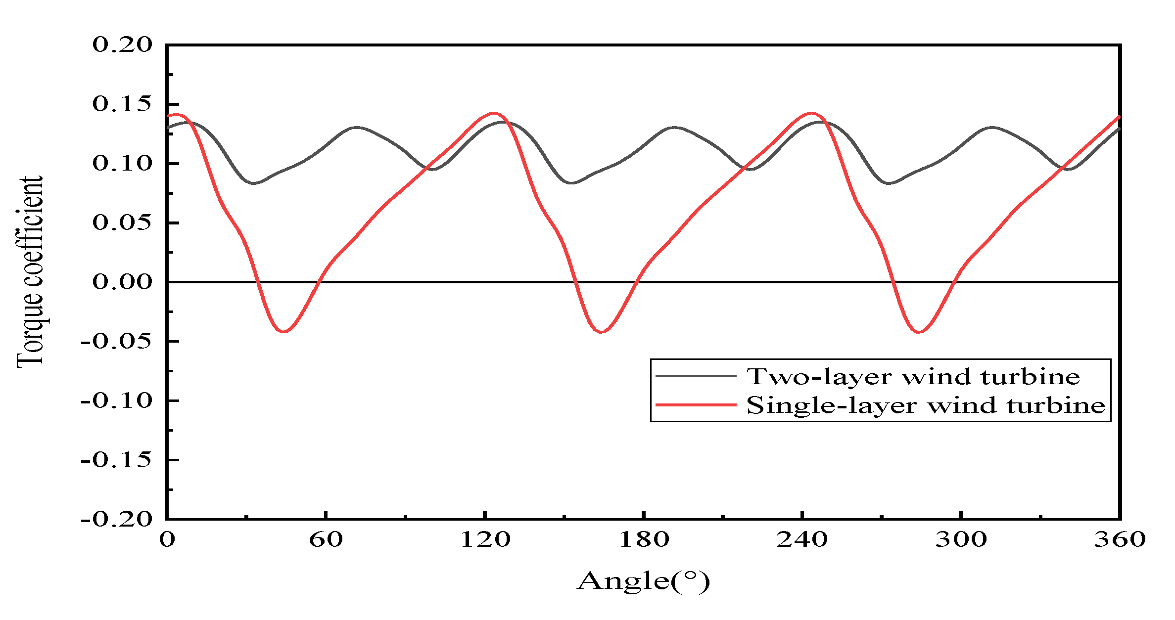
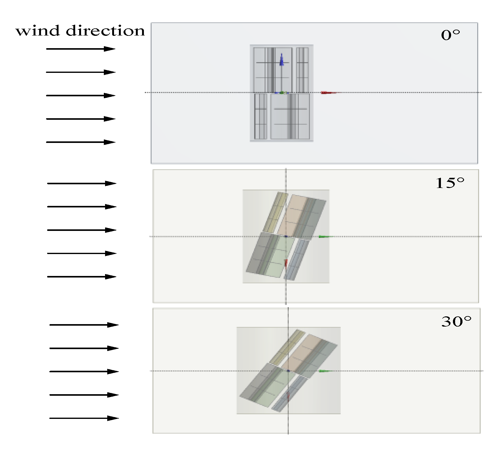
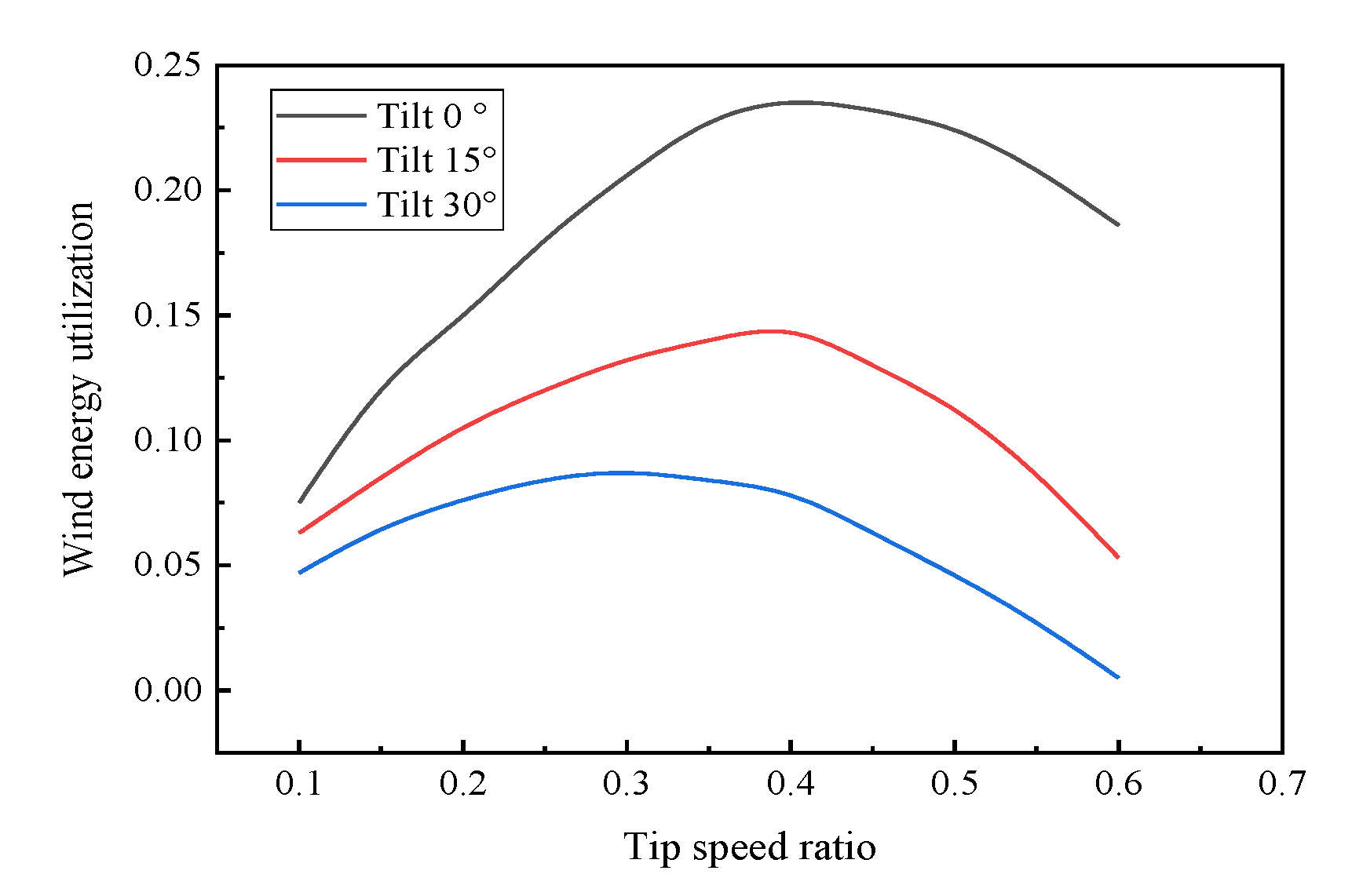
4. Wind Turbine Modeling

Figure 10 shows the 3D model of the multi-DOF deflecting-type permanent-magnet synchronous wind turbine. The turbine usually comprises of a wind wheel, vertical shaft, bearing, bearing seat, tower, footing, coupling, multi-DOF deflecting-type PMSG, controller, and an inverter [24,25,26]. According to Figure 10, the wind turbine has a double-layer wheel structure, and each layer has three shafts. Figure 11a shows a two-dimensional structural model of the double-layer wind wheel, whereas Figure 11b shows a 3D structural model of the one-layer wind wheel. Table 4 lists the specific parameters of the wind turbine obtained from the measured data of the wind turbine prototype from the wind power laboratory at Hebei University of Science and Technology.

Performance Analysis

A flow field analysis was performed using the CFX module of the ANSYS Workbench, by simulating the operation of the wind turbine in practical operations. The boundary condition setting is shown in Figure 12. The wind enters through the inlet, with speeds ranging from 2.5 m/s to 13 m/s. The pressure outlet has a static pressure of 0 Pa. The left and rights sides are set as a symmetrical structure, and the top and bottom are set to the wall. After the boundary conditions are established, the meshing is performed. Figure 13 is a schematic diagram of meshing. During the division process, the selected mesh type, grid layout, and algorithm will directly affect the accuracy of the numerical simulation. This study adopts the automatic mesh generation method, which is a relatively classic mesh division method in software. The specific solver parameters are presented in Table 5.
In the calculation process, the wind speed of the inflow airflow was maintained constant at 5 m/s, and the tip speed ratio changed between 0–1 with a variation in the corresponding parameters. Figure 14 shows the variation curve of the wind energy utilization coefficient with respect to the tip speed ratio, which ranges between 0.1 and 0.9; the wind energy utilization rate first increases and subsequently decreases with increasing tip speed ratio. The wind energy utilization coefficient becomes maximum at a tip speed ratio of 0.5. The wind turbine can maintain the maximum utilization efficiency of the wind energy if the rotation speed is stabilized at this value.
Figure 15 shows the torque coefficient comparison curves of the three blades in one rotation period where the torque coefficient curves are roughly sinusoidal, and the sum of the torques of the three blades is considerably more stable than the individual blade torques. Figure 16 shows the torque coefficient comparison curves of the single- and double-layer wind wheels. The torque coefficient of the double-layer wind wheel is stronger and more stable than that of the single-layer wind wheel.
Figure 17a,b show the top view and 3D model for different stagger angles of the two wind wheel layers, respectively. The rotation space is symmetric; hence, cutting the rotation period by half will allow a 180° rotation. The wind wheel has three blades; thus, the stagger angle of each blade is 60 ° . We considered 0 ° , 20 ° , 40 ° , and 60 ° stagger angles to analyze the torque coefficients; the corresponding results are depicted in Figure 18, which shows that the torque coefficient stabilizes with increasing stagger angle, and the torque coefficient is best when the stagger angle reaches 60 ° .
The wind turbine deflection mode was analyzed in Figure 19, to verify the performance reliability of the multi-DOF deflecting-type PMSWG. The comparison results of the wind energy utilization at different deflecting angles are shown in Figure 20. The wind energy utility decreases as the deflection angle increases; however, the PMSG can still operate in a rational range.

5. Multi-DOF Deflection-Type PMSWG: Transient Analysis with Deflection

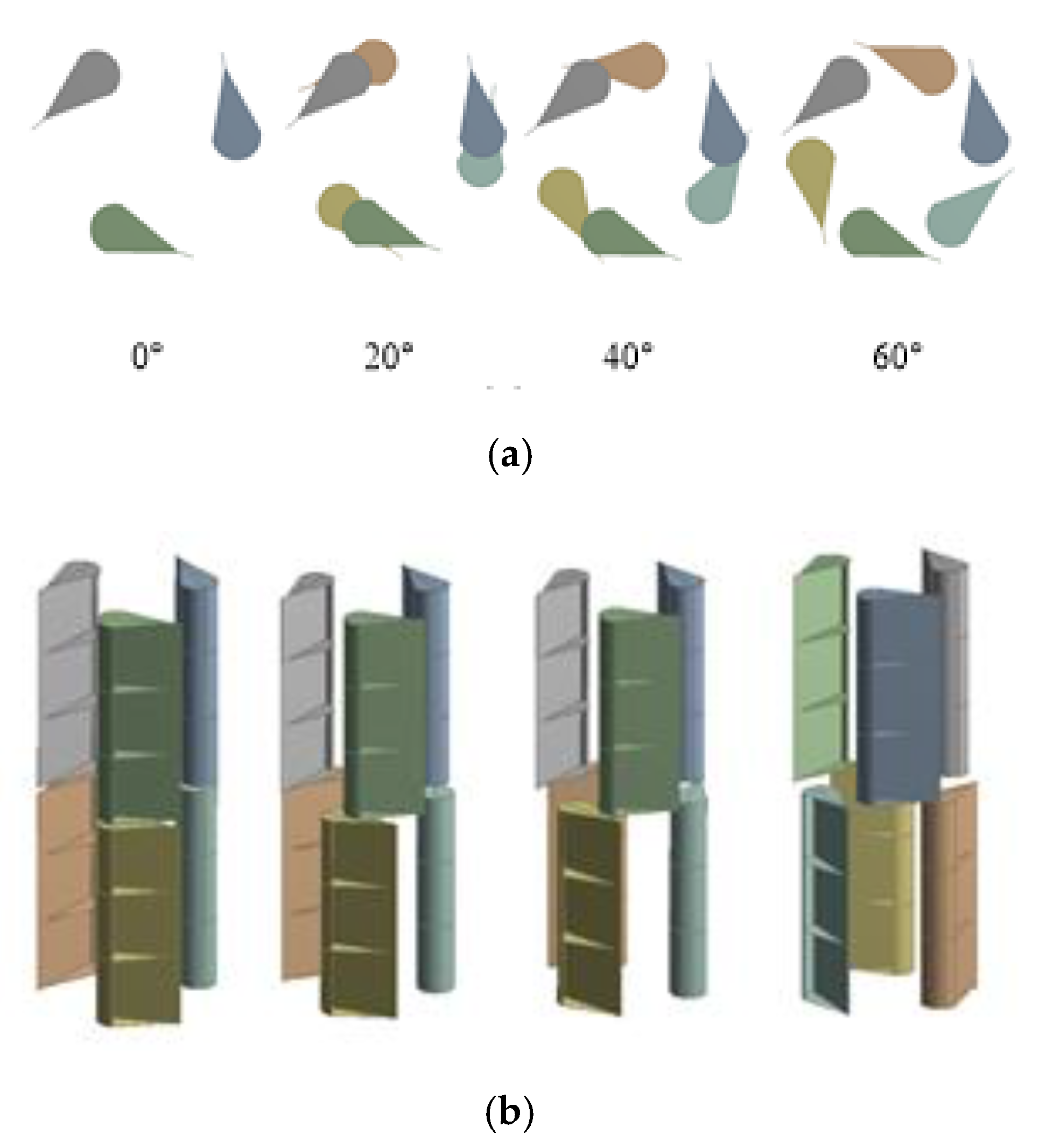
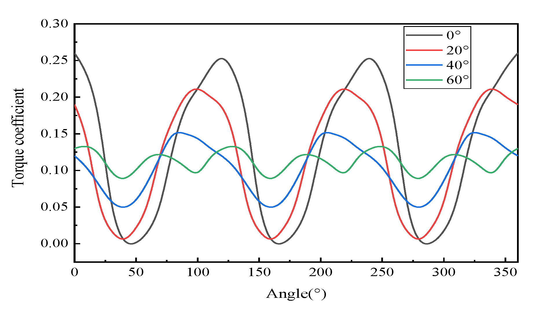
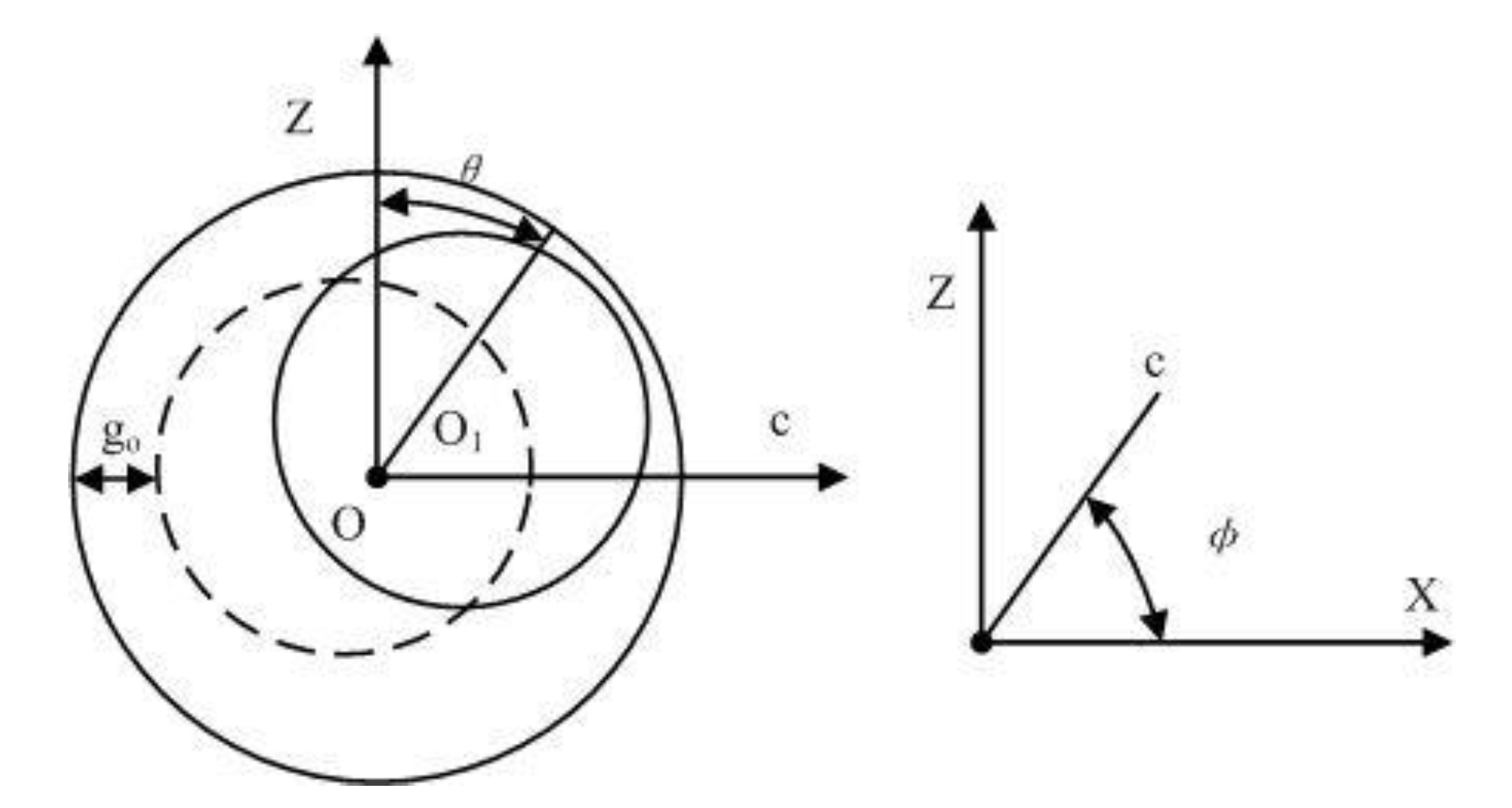
5.1. Rotor Deflection Motion

The proposed generator performs deflection in multiple DOF, so that the rotor can achieve eccentric motion. The air-gap distribution between the stator and the rotor becomes unequal and changes as the rotor deviates from its position when eccentric motion begins. Figure 21 depicts the eccentric motion of the rotor.
Here, we assume that the spherical coordinates of the rotor are ( α , β , γ ) before rotor deflection. Following rotor deflection, the deflection displacement is significantly smaller compared with the rotor radius displacement. At this point, the expression of the air-gap length in any plane (such as the OCZ plane) in the original coordinate system is given as:
g 0 ( θ ) = | OB | sin ( θ ) + Δ z cos ( θ ) ,
where θ is the angle at which the rotor center is deflected relative to the z-axis.
Based on Figure 22, as the OC axis is obtained by rotating the XOY plane around the z-axis at angle φ , the length of OC can be expressed as follows:
| OC | = Δ x sin ( φ ) + Δ y cos ( φ ) .
Substituting Equation (1) in Equation (2), the length of the air-gap at any position of the rotor core represented in spherical coordinates can be expressed as follows:
g 01 ( θ , φ ) = ( Δ x sin ( φ ) + Δ y cos ( φ ) ) · sin ( θ ) + Δ z cos ( θ ) ] .
Hence, the air-gap post rotor deflection expression is:
  g 0 ( θ , φ ) = g 0 g 01 = g 0 [ ( Δ x sin ( φ ) + Δ y cos ( φ ) ) · sin ( θ ) + Δ z cos ( θ ) ] ,
where g 0 is the equally distributed air-gap length between the stator and the rotor before rotor deflection.

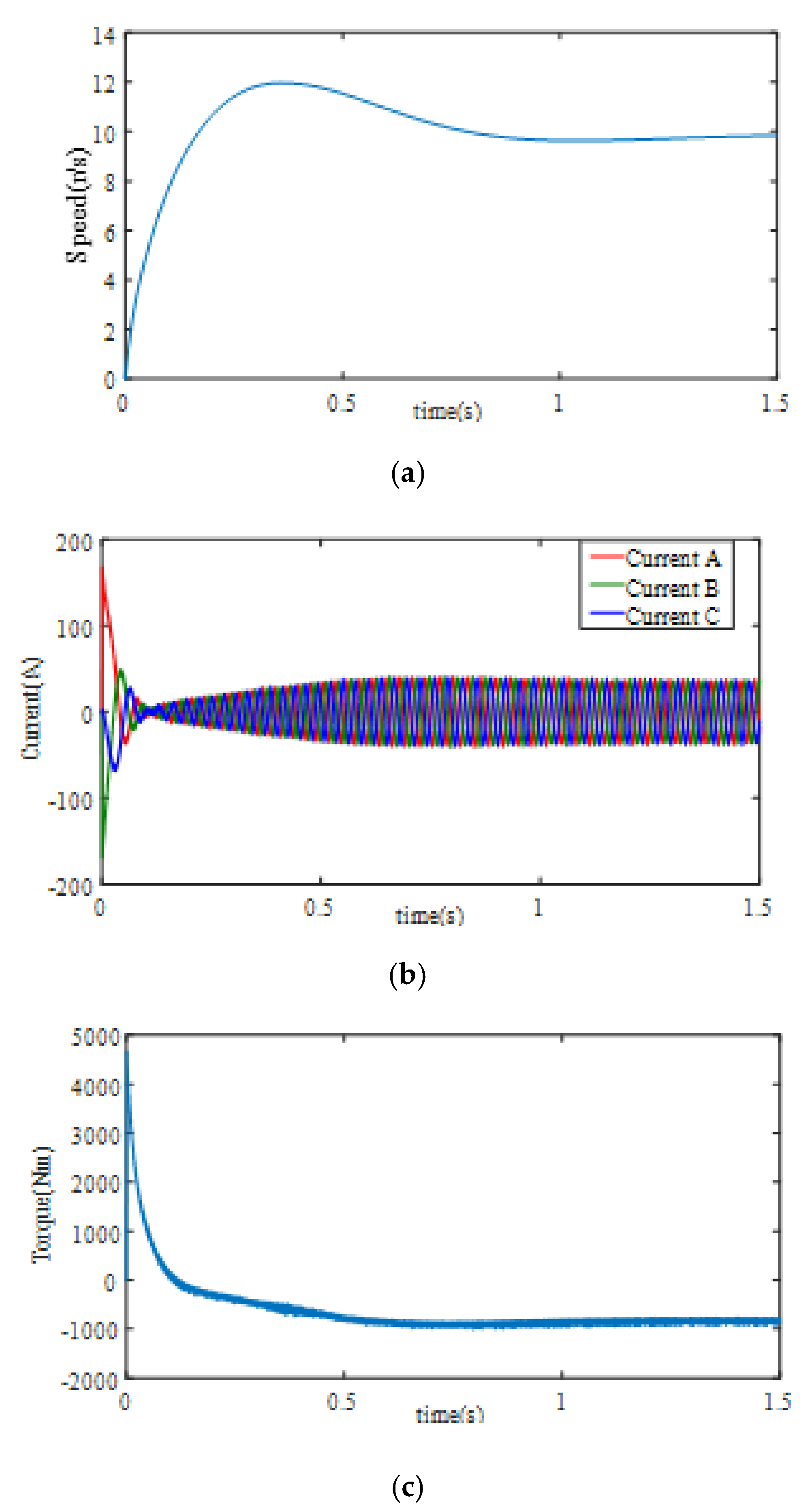
5.2. Transient Analysis Post Deflection via Simulation

The operation of the generator automatically adjusts when the wind direction changes; hence, the generator has to operate in the electric state for a short duration. The working conditions at rotor deflections of 0°, 15°, and 30° were compared. During the simulation, the unstable state at the startup was ignored. There are three phase windings on stator, which are phase A, phase B and phase C. Considering phase A as an example, the comparison plots of the phase voltage, phase current, flux linkage, and induced voltage are shown in Figure 23, Figure 24, Figure 25, and Figure 26, respectively.
In Figure 23 and Figure 25, the amplitude and phase of the voltage and flux linkage remain nearly equal before and after a deflection. Therefore, the influence of harmonics on voltage and flux linkage is minimal. According to Figure 24 and Figure 26, the amplitudes of current and induced voltage decrease, however, the induced voltage curve is relatively smoother than that of the current; thus, harmonics have a smaller effect on the induced voltage than the current. As can be observed here, harmonics can not only affect generator characteristics, but also reduce service life. Therefore, controlling harmonics is essential.

5.3. Experimental Transient Analysis Post Deflection

We used an experimental platform to analyze the working conditions at rotor deflections of 0°, 15°, and 30°. Figure 27 shows the corresponding experimental setup, and 2D models of the stator winding scheme, 3D model of the rotor, and 3D model of the stator are shown in Figure 28, Figure 29, and Figure 30, respectively.
Only the phase voltage and induced voltage were compared, because the phase current can be calculated from the phase voltage, and the flux linkage cannot be directly measured using an oscilloscope. The oscilloscope results showed excessive harmonics; hence, we eliminated these harmonics using a low-pass filter in Matlab. Phase A is considered as an example here, and the impact of rotor deflection on phase and induced voltages are shown in Figure 31 and Figure 32, respectively.
Figure 31 and Figure 32 show that the variation trends of phase and induced voltage remain almost identical before and after deflection. Moreover, both parameters exhibit a sinusoidal change over time. The voltage and back electro-motive force are slightly distorted post deflection, owing to harmonics; hence, the proposed generator can operate normally within the maximum deflection range.

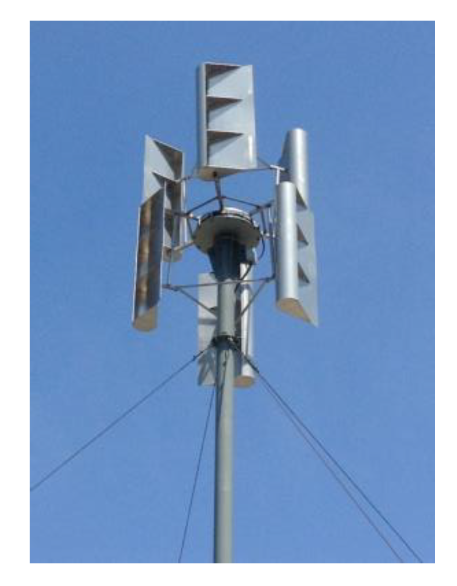
5.4. Wind Tunnel Experiment

The wind tunnel experiment was used to study the relation between voltage variation and wind direction. The direction of the wind in the tunnel changed from 30 ° to 30 ° . The generator used is shown in Figure 27 to simulate a wind turbine (with bearing, bearing seat, tower, footing, coupling, controller, and inverter included). Figure 33 shows the wind turbine prototype, and the basic parameter of the wind tunnel model is shown in Table 6.
The generator power generation characteristic curves are obtained in Figure 34. Figure 34a–c show the speed, current and torque curves of the generator, respectively.
Figure 35 shows the voltage comparison curves post deflection. The voltage nearly maintained a peak value when the rotor deflection angle changed with the change of wind direction. Moreover, the voltage variation was substantial when no deflection occurred in the rotor. Thus, the wind tunnel experiment confirmed that the multi-DOF deflection-type PMSWG can significantly improve wind utility. The power and efficiency comparison curves post-deflection are presented in Figure 36 and Figure 37, respectively. Both power and efficiency can improve by approximately 8 % to 10 % when compared with no deflection in the rotor, making it more attractive than other wind generators.

6. Discussion

To improve the utilization rate of wind energy, some researchers have proposed new wind turbine models, while others have analyzed different control and frequency regulation strategies [7,8,9,10,11,12]. In addition, several studies have focused on multi-DOF generators in a different field, such as the magnetic field, and a modeling analysis, rotor dynamics characteristics, and multiphysics coupling analysis. This article draws on the essence of the above two research areas. We use the characteristics of multi-DOF theory into wind turbine analysis to propose a high quality novel wind turbine model. The results from transient analysis with deflection relying on simulations and experiments and wind tunnel experiments have shown that multi-DOF PMSWG can effectively improve the utilization rate of wind energy. This result provides a reference for optimizing the structure of wind generators and improving their operational stability.
Due to the fact that this wind turbine represents a novel type of structure, two improvements can be performed in the future. First, the structure needs to be improved to realize multi-DOF movement, stability, and collaboration of every component in the structure. Second, the wind turbine can only work in off-grid conditions. The grid-connection process should be considered, to use the wind turbine generation system connected to a grid.

7. Conclusions

This study focused on a deflecting-type PMSG used as a wind turbine. The model parameters and the mechanism of the generator were determined through simulation and experimental analyses. The magnetic field model and torque were simulated, and its air-gap magnetic field characteristics were calculated. Both the aerodynamics and power generation performance of the complete wind turbine were considered. Transient analysis post deflection was performed relying on the simulation and experimental results; further, the wind tunnel experiment was used to compare voltage variation according to the wind direction. The feasibility of the generator design was verified. In addition to the calculated data, the simulation and experimental results provide a theoretical basis and supporting data for the optimization of wind power generation systems.

Author Contributions

Writing—review and editing, methodology, formal analysis, FEA software, W.D.; project administration, supervision, funding acquisition, Z.L.; project administration, supervision, funding acquisition, H.S. (Z.L. and H.S. contributed equally to this work as co-correspondent author); MATLAB software, data curation, J.Z. All authors have read and agreed to the published version of the manuscript.

Funding

Funded by the National Natural Science Foundation of China (51877070, 51577048); Funded by the Natural Science Foundation of Hebei Province (E2018208155, E2018210044); Funded by the High-level Talents of Hebei Province (A201905008); Hebei Province Higher Education Science and Technology Research Key Project (ZD2018228).

Conflicts of Interest

The authors declare no conflict of interest.

References

  1. Blaabjerg, F.; Ma, K. Future on power electronics for wind turbine systems. IEEE J. Emerg. Sel. Top. Power Electron. 2013, 1, 139–152. [Google Scholar] [CrossRef]
  2. Du, P.; Wang, J.Z.; Yang, W.D.; Niu, T. A novel hybrid model for short-term wind power forecasting. Appl. Soft. Comput. 2019, 80, 93–106. [Google Scholar] [CrossRef]
  3. Davidson, M.R.; Zhang, D.; Xiong, W.; Zhang, X.; Karplus, V.J. Modeling the potential for wind energy integration on China’s coal-heavy electricity grid. Nat. Energy 2016, 1, 1–7. [Google Scholar] [CrossRef]
  4. Polinder, H.; Ferreira, J.A.; Jensen, B.B.; Abrahamsen, A.B.; Atallah, K.; McMahon, R.A. Trends in Wind Turbine Generator System. IEEE J. Emerg. Sel. Top. Power Electron. 2013, 1, 174–185. [Google Scholar] [CrossRef]
  5. Patil, N.S.; Bhosle, Y.N. A review on wind turbine generator topologies. In Proceedings of the 2013 International Conference on Power, Energy and Control (ICPEC), Dindigul, India, 6–8 February 2013. [Google Scholar]
  6. Yang, X.; Patterson, D.; Hudgins, J. Permanent magnet generator design and control for large wind turbines. In Proceedings of the 2012 IEEE Power Electronics and Machines in Wind Applications, Denver, CO, USA, 16–18 July 2012. [Google Scholar]
  7. Bhutto, D.K.; Ansari, J.A.S.; Bukhari, S.H.; Chachar, F.A. Wind Energy Conversion Systems (Wecs) Generators: A Review. In Proceedings of the 2019 2nd International Conference on Computing, Mathematics and Engineering Technologies (iCoMET), Sukkur, Pakistan, 30–31 January 2019. [Google Scholar]
  8. Zhang, L.; Zhou, B.; Cheng, F.S.; Zhang, Y.S. Modeling and Dynamic Simulation of a Novel Doubly Salient Electro-Magnetic Wind Power Generator System. In Proceedings of the 2009 World Non-Grid-Connected Wind Power and Energy Conference, Nanjing, China, 24–26 September 2009. [Google Scholar]
  9. Zamani, M.H.; Riahy, G.H.; Abedi, M. Rotor-Speed Stability Improvement of Dual Stator-Winding Induction Generator-Based Wind Farms by Control-Windings Voltage Oriented Control. IEEE Trans. Power Electron. 2016, 31, 5538–5546. [Google Scholar] [CrossRef]
  10. Bai, Y.R.; Kou, B.Q.; Chan, C.C. A Simple Structure Passive MPPT Standalone Wind Turbine Generator System. IEEE Trans. Magn. 2015, 51, 1–4. [Google Scholar] [CrossRef]
  11. Cui, Y.; Song, P.; Wang, X.S.; Yang, W.X.; Liu, H. Wind Power Virtual Synchronous Generator Frequency Regulation Characteristics Field Test and Analysis. In Proceedings of the 2018 2nd International Conference on Green Energy and Applications (ICGEA), Singapore, 24–26 March 2018. [Google Scholar]
  12. Li, X.M.; Xiao, Z.; Song, D.L. A Novel Outer Rotor Axial Primary Magnetic Circuit Permanent Magnet Generator. In Proceedings of the 2015 International Conference on Advanced Mechatronic Systems (ICAMechS), Beijing, China, 22–24 August 2015. [Google Scholar]
  13. Li, Z.; Wang, Q.J. The present research and development situation of permanent magnet spherical motor of multi-dimensions. Small Spec. Electr. Mach. 2006, 34, 7–11. [Google Scholar]
  14. Li, Z.; Lun, Q.Q.; Xue, Z.T.; Wang, Q.J. Calculation and analysis of magnetic field and torque characteristics for 3-DOF deflection type PM motor. Trans. China Electrotech. Soc. 2017, 32, 81–90. [Google Scholar]
  15. Li, Z.; YU, X.X.; Zhang, L.W.; Xue, Z.T.; Wang, Q.J. Design and Analysis of PM Deflection Type Synchronous Wind Generator. Small Spec. Electr. Mach. 2017, 45, 14–21. [Google Scholar]
  16. Li, Z.; Chen, Q.M.; Wang, Q.J. Rotor dynamics characteristic analysis of Multi-degree-of-freedom permanent magnet synchronous motor. Trans. China Electrotech. Soc. 2019, 34, 2269–2276. [Google Scholar] [CrossRef] [Green Version]
  17. Li, Z.; Liu, L.Q.; Guo, P. Modeling and Dynamics Analysis of Permanent Magnet Three-DOF Motor. Electr. Appl. 2018, 11, 37–42. [Google Scholar]
  18. Li, Z.; Chen, Q.; Wang, Q.J. Analysis of Magnetic-Thermal-Solid Coupling Fields of Multi-Degree of Freedom Permanent magnet motor. Small Spec. Electr. Mach. 2018, 46, 40–44. [Google Scholar]
  19. Meng, H.M.; Li, P.F.; Lin, Z.W.; Hu, Y. Multi-degree of freedom optimization control for large inertia wind energy conversion system using model predictive approach. In Proceedings of the 2017 29th Chinese Control and Decision Conference (CCDC), Chongqing, China, 28–30 May 2017. [Google Scholar]
  20. Zhang, M.H.; Li, M.T.; Sun, L.N. A Multi-DOF Ultrasonic Motor Using In-plane Deformation of PZT Elements and Its Driving Circuit. In Proceedings of the 2007 International Conference on Mechatronics and Automation, Harbin, China, 5–8 August 2007. [Google Scholar]
  21. Xiao, S.C.; Qin, M. Electromagnetic design and simulation for large-scale double-stator direct driving permanent magnet wind generator. Motor Control Appl. 2013, 40, 45–50. [Google Scholar]
  22. Lv, Y.N.; Peng, X.; Wang, B.Y. Electromagnetic design of 2MW direct drive permanent magnet synchronous wind generator. J. Hunan Inst. Eng. 2016, 206, 15–18. [Google Scholar]
  23. Li, Z.; Zhang, L.W.; YU, X.X.; Wang, Q.J. Electromagnetic Modeling and Transient Analysis of a Deflection Type Permanent Magnet Synchronous Wind Generator. Mach. Des. Manuf. 2019, 5, 217–221. [Google Scholar]
  24. Li, Z.; Gao, P.F.; Sun, T.T.; Xue, Z.T.; Wang, Q.J. Numerical simulation and analysis of characteristics of drag type vertical axis wind turbine for distributed energy system. Trans. China Electrotech. Soc. 2017, 32, 155–163. [Google Scholar]
  25. Kong, L.; Cai, G.; Chen, C.; Xing, L. Modeling and grid-connected control of proactive permanent magnet direct-driven wind turbine based on energy storage of hydrogen. Trans. China Electrotech. Soc. 2017, 18, 276–285. [Google Scholar]
  26. Brain, H.; Andrew, C.; Ger, K. Alow-order model for offshore floating vertical axis wind turbine aerodynamics. IEEE Trans. Ind. Appl. 2017, 53, 512–520. [Google Scholar]
Figure 1. Basic structure of the generator.
Energies 13 01524 g001
Figure 2. Region division of the permanent magnet.
Energies 13 01524 g002
Figure 3. Three-dimensional distribution plot of B r obtained through the analytical method.
Energies 13 01524 g003
Figure 4. Finite element solution model of the generator.
Energies 13 01524 g004
Figure 5. Pole magnetic field distribution of the generator.
Energies 13 01524 g005
Figure 6. Magnetic dense cloud plot of the rotor.
Energies 13 01524 g006
Figure 7. Three-dimensional distribution plot of B r obtained through the finite element analysis.
Energies 13 01524 g007
Figure 8. Air-gap flux density comparison diagram for θ = 90°.
Energies 13 01524 g008
Figure 9. Transient rotation torque.
Energies 13 01524 g009
Figure 10. Three-dimensional model of the wind turbine.
Energies 13 01524 g010
Figure 11. Wind wheel model: (a) two-dimensional structural model of the double-layer wind wheel; (b) 3D structural model of the one-layer wind wheel.
Energies 13 01524 g011
Figure 12. Boundary condition setting.
Energies 13 01524 g012
Figure 13. Schematic diagram of meshing.
Energies 13 01524 g013
Figure 14. Tip speed ratio–wind energy utilization coefficient curve.
Energies 13 01524 g014
Figure 15. Torque coefficient comparison curves of the three blades.
Energies 13 01524 g015
Figure 16. Torque coefficient comparison curves of single- and double-layer wind turbines.
Energies 13 01524 g016
Figure 17. Stagger angles of two wind wheel layers. (a) Top view of different stagger angles. (b) Three-dimensional model of different stagger angles.
Energies 13 01524 g017
Figure 18. Torque coefficient comparison curves at different stagger angles.
Energies 13 01524 g018
Figure 19. Wind turbine deflection modes.
Energies 13 01524 g019
Figure 20. Comparison results of wind energy utilization at different deflecting angles.
Energies 13 01524 g020
Figure 21. Rotor eccentric motion diagram; (a) Without eccentricity; (b) With eccentricity.
Energies 13 01524 g021
Figure 22. Projection at the center of the rotor in any plane.
Energies 13 01524 g022
Figure 23. Voltage comparison diagram of phase A winding in three states.
Energies 13 01524 g023
Figure 24. Current comparison diagram of phase A winding in three states.
Energies 13 01524 g024
Figure 25. Magnetic linkage comparison diagram of phase A winding in three states.
Energies 13 01524 g025
Figure 26. Induced voltage comparison diagram of phase A winding in three states.
Energies 13 01524 g026
Figure 27. Experimental setup for the generator.
Energies 13 01524 g027
Figure 28. Two-dimensional model of the stator winding scheme.
Energies 13 01524 g028
Figure 29. Three-dimensional model of the rotor.
Energies 13 01524 g029
Figure 30. Three-dimensional model of the stator.
Energies 13 01524 g030
Figure 31. Phase voltage comparison diagram of phase A winding in three states, based on the experiment.
Energies 13 01524 g031
Figure 32. Induced voltage comparison diagram of phase A winding in three states based on the experiment.
Energies 13 01524 g032
Figure 33. Wind turbine prototype.
Energies 13 01524 g033
Figure 34. Generator power generation characteristic curve based on the experiment; (a) Generator speed curve; (b) Generator current curve; (c) Generator torque curve.
Energies 13 01524 g034
Figure 35. Voltage comparison curves post deflection.
Energies 13 01524 g035
Figure 36. Comparison of power curves post deflection.
Energies 13 01524 g036
Figure 37. Comparison of efficiency curves post deflection.
Energies 13 01524 g037
Table 1. Basic parameters of the deflecting-type PMSG.
ParameterValues
Rate power/kW10
Rate current/A13.5
Efficiency at rated operating point88 %
Geometric dimension3
Mass of generator/kg15
Outer diameter of rotor/mm43
Inner diameter of rotor/mm36
Outer diameter of stator/mm100
Inner diameter of stator/mm56
Rated voltage/V120
Rated speed/r/min600
Number of magnetic pole pairs4
Permanent magnet materialNdFeB
Number of parallel branches
Residual magnetic flux density/T
1
1.4
Air gap width/mm1
Table 2. The solver parameters.
Step SizeStep NumberOperation TimeNonlinear Residual
0.0005 s 1000.05 s1.0 × 10 4
Table 3. Value of deflection torques.
AngleX-Axis Deflection Torque Value (N*m)Y-Axis Deflection Torque Value (N*m)
0 ° 0.0199230.011817
5 ° 1.19791.2316
10 ° 1.08111.0864
15 ° 0.949530.97457
20 ° 0.853780.85074
25 ° 0.78260.78247
30 ° 0.741230.71937
Table 4. Specific parameters of the wind turbine.
ParameterValueParameterValue
Height of the blade0.3 mRated power10 kW
Radius of the blade0.65 mRadius of shaft0.2 m
Height of shaft5 m Starting wind speed2–3 m/s
Table 5. The solver parameters.
Reynolds NumberTurbulence ModelNo. of MeshesResidual TargetIterations
6.0 × 10⁵Standard k-e model240,0001.0 × 10−4200
Table 6. Basic parameter of Wind tunnel model.
Low Speed Experimental SectionHigh Speed Experimental Section
Model sizeWidth: 4 m; Long: 24 m; Height: 3 m
Maximum wind velocity ≥30.0 m/s≥80.0 m/s
Velocity instability ≤0.6%≤0.2%
Velocity field inhomogeneity ≤0.4%≤0.2%
Turbulivity≤0.4%≤0.2%

