Article

Techno-Economic and Environmental Evaluations of Decarbonized Fossil-Intensive Industrial Processes by Reactive Absorption & Adsorption CO2 Capture Systems

Department of Chemical Engineering, Faculty of Chemistry and Chemical Engineering, Babes—Bolyai University, Arany Janos 11, RO-400028 Cluj-Napoca, Romania
*
Author to whom correspondence should be addressed.
Energies 2020, 13(5), 1268; https://doi.org/10.3390/en13051268
Submission received: 17 January 2020 / Revised: 4 March 2020 / Accepted: 6 March 2020 / Published: 9 March 2020

Abstract

:
Decarbonization of energy-intensive systems (e.g., heat and power generation, iron, and steel production, petrochemical processes, cement production, etc.) is an important task for the development of a low carbon economy. In this respect, carbon capture technologies will play an important role in the decarbonization of fossil-based industrial processes. The most significant techno-economic and environmental performance indicators of various fossil-based industrial applications decarbonized by two reactive gas-liquid (chemical scrubbing) and gas-solid CO2 capture systems are calculated, compared, and discussed in the present work. As decarbonization technologies, the gas-liquid chemical absorption and more innovative calcium looping systems were employed. The integrated assessment uses various elements, e.g., conceptual design of decarbonized plants, computer-aided tools for process design and integration, evaluation of main plant performance indexes based on industrial and simulation results, etc. The overall decarbonization rate for various assessed applications (e.g., power generation, steel, and cement production, chemicals) was set to 90% in line with the current state of the art in the field. Similar non-carbon capture plants are also assessed to quantify the various penalties imposed by decarbonization (e.g., increasing energy consumption, reducing efficiency, economic impact, etc.). The integrated evaluations exhibit that the integration of decarbonization technologies (especially chemical looping systems) into key energy-intensive industrial processes have significant advantages for cutting the carbon footprint (60–90% specific CO2 emission reduction), improving the energy conversion yields and reducing CO2 capture penalties.

1. Introduction

Global warming and climate change are fundamental issues nowadays. In order to significantly reduce global warming for long-term sustainable development, the greenhouse gas emissions (especially the fossil ones) need to be significantly cut and decoupled from economic growth [1]. Along this line, the industrial and transport sectors are facing important modifications and restructuring with the aim of reducing the fossil energy sources as required for the development of an economy with a low carbon footprint. Among industrial applications with significant greenhouse gas emissions, the heat, and power generation, iron and cement production, and various fossil-based chemical systems are the biggest contributors. To illustrate the major importance of these industrial sectors and to consider the global greenhouse gas emissions one can mention that the coal-based power generation is responsible by more than 10 Gt CO2 from the 33.1 Gt CO2 emitted globally in 2018 [2], production of iron and steel counts for about 6% of global CO2 emissions [3], and the cement production counts for 5% of global CO2 emissions [4]. Accordingly, the fossil-intensive industrial processes need significant changes in forthcoming years to efficiently contribute to the global effort of reducing carbon emissions.
As possible technical and scientific options to cut the fossil carbon emissions, a broad range of measures can be applied, ranging from promoting renewable energy, increasing the energy conversion, and utilization yields too large scale deployment of carbon capture, utilization and storage (CCUS) technologies [5]. These technologies are seen as important options for the medium time horizon to allow a smoothly transition from the current fossil-based economy to a future low carbon one. For the integration of the CO2 capture process into various energy-intensive applications, several conceptual options are already available and widely evaluated in the literature, e.g., pre-, post- and oxy-fuel combustion methods [6]. Once captured, CO2 can be used as raw material for various processes (e.g., production of various chemicals and fuels), stored in appropriate geological formations (e.g., saline aquifers) or used for increasing the oil/gas recovery yields [7].
This work is assessing some key fossil fuel-intensive industrial applications in view of energy and cost-effective process decarbonization. The selected industrial applications are power generation, iron and steel production, cement production, as well as producing chemicals which can also be used as decarbonized energy carriers (e.g., hydrogen). The chemical absorption (scrubbing) method [8] and the innovative chemical/calcium looping cycles based on reactive adsorption systems [9] were evaluated as decarbonization technologies. Apart from the carbon footprint reduction, the overall energy conversion yields, as well as other techno-economic and environmental performance indicators, represent important elements in the present evaluations. Similar non-carbon capture plants are also assessed to quantify the various penalties imposed by decarbonization (e.g., energy, raw materials, and utility consumptions, overall energy efficiency, main economic factors). The decarbonized plant concepts have a 90% CO2 capture rate, a value which is in line with assessment methodology of CO2 capture technologies presented in relevant literature sources, e.g., International Energy Agency Greenhouse Gas Programme (IEAGHG) reports for decarbonization of iron and steel production [3] or cement production [4]. In addition to technical and environmental indicators, the economic impact of process decarbonization is also presented considering key performance indexes.
The selected industrial applications were subject to various technical investigations ranging from the conceptual design of decarbonized plants and evaluation of CO2 capture unit mass and energy integration analysis, usage of computer-aided tools for process design, and integration to the evaluation of main plant performance indexes based on industrial and simulation results. The key novelty aspect of the presented work is to provide an integrated in-depth techno-economic and environmental evaluation methodology of decarbonized industrial processes.

2. Carbon Capture Technologies for Efficient Decarbonization of Industrial Applications

As decarbonization technologies, two carbon capture methods were assessed in view of integration into fossil-intensive industrial applications. The first option considers a mature technology based on chemical scrubbing employing alkanolamines [10]. This technology represents the conventional option when acid gas removal (e.g., CO2, sulfur compounds, etc.) is required in various chemical industrial processes (e.g., natural gas reforming for ammonia synthesis, sulfur removal from oil refinery, etc.). For this main reason, the reactive gas-liquid absorption technology was considered as potential decarbonization process for the evaluated energy-intensive industrial applications. To illustrate this decarbonization technology, Methyl-DiEthanol-Amine (MDEA) was selected as a chemical solvent. The selection of the MDEA solvent was based on the following key advantages over more conventional Mono-Ethanol-Amine (MEA): higher CO2 loadings (1 mole CO2/mole MDEA vs. up to 0.5 mole CO2/mole MEA), higher solution concentration (50% vs. 30%), lower degradation, corrosion and toxicity, better thermal stability, etc. [11]. The overall chemical reaction for MDEA-based decarbonization is presented below:
C O 2 + H 2 O + M D E A M D E A H + + H C O 3
For this decarbonization technology, the above global chemical reaction is used in a cycle, as presented in Figure 1. The gas to be decarbonized is treated in the absorption column being put in contact with an MDEA aqueous solution (50% wt.). The loaded (rich) solvent is pumped in a separate column where using heat, the CO2 is desorbed, and thus, the solvent regenerated. The regenerated (lean) solution is pumped back in the absorption column (some make-up being necessary to cover the solvent losses). The CO2 is treated for moisture removal and compressed to the final delivery pressure (120 bar) prior to storage/utilization. A key element of this decarbonization technology represents the heat consumption (at the bottom of the desorption column) for CO2 desorption and solvent regeneration. Currently, for the post-combustion CO2 capture configurations applied to fossil-based power generation plants (10–15 volumetric percentages of CO2 content in the gas to be treated), this heat duty is about 3 GJ/t CO2 [12]. For pre-combustion capture configurations, the heat consumption for solvent regeneration is significantly reduced to about 0.6–0.8 GJ/t due to pressure reduction [13].
The second evaluated decarbonization option makes use of an innovative reactive system based on calcium adsorption (Calcium Looping—CaL). Similar with chemical scrubbing option presented above, the chemical looping cycle can also be used for pre- and post-combustion decarbonization configurations. This technique uses two separate reactors for decarbonization as follow [9]:
The carbonation reactor where the gas to be decarbonized is put in contact with the calcium sorbent for CO2 capture. The reactions for pre- and post-combustion decarbonization are exhibited below:
Post combustion   capture :   C O 2 + C a O C a C O 3
Pre combustion   capture :   C O + H 2 O + C a O C a C O 3 + H 2
Calcination reactor when CaCO3 is thermally disintegrated to CaO and CO2 according to the next chemical reaction:
C a C O 3 C a O + C O 2
The innovative calcium looping method was selected as decarbonization technology for the fossil-intensive industrial applications based on the following reasons: it represents a promising technology in reducing the CO2 capture energy and cost penalties, possibility to use the spent sorbent (deactivated calcium sorbent) within the main process, sorbent lower cost and large availability, etc. [14]. For this decarbonization technology, the conceptual design is presented in Figure 2. As for gas-liquid absorption decarbonization technology, the calcium looping cycle requires an additional energy input (for the calcination reactor). In the calcination reactor, some sort of fuel (e.g., natural gas, syngas, coal, etc.) is to be oxy-combusted for providing the required energy input for the calcium carbonate decomposition. Oxygen must be used for combustion in order not to dilute the CO2 captured stream with nitrogen. Different for gas-liquid decarbonization technology, the CaL cycle is operating at significantly higher temperatures: carbonation (CO2 fixation) reactor to 500–650 °C and calcination reactor to about 850–1000 °C [15]. These operating conditions enable high-temperature heat recovery with positive consequences on the overall energy conversion yield [16].

3. Conceptual Designs, Main Design Assumptions, and Process Integration Elements

To illustrate the influence of plant decarbonization over the most relevant techno-economic and environmental indexes, some key fossil-intensive industrial applications were considered as follow:
  • Cases 1: Coal-based gasification power plants;
  • Cases 2: Coal-based super-critical power plants;
  • Cases 3: Integrated iron & steel plants;
  • Cases 4: Cement production plants.
The evaluated gasification plants consider both pre- and post-combustion decarbonization scenarios is based on the Integrated Gasification Combined Cycle (IGCC) design [17]. The conventional gasification-based power plant design without carbon capture involves a partial oxidation process (with oxygen and steam) of the solid fuel to syngas (mainly a mixture of hydrogen and carbon monoxide). Further, the syngas is treated for sulfur removal in an acid gas removal unit, and the clean gas is used for power generation in a combined cycle gas turbine unit [18].
For the pre-combustion capture, the syngas is decarbonized either by gas-liquid absorption or calcium looping, and the hydrogen-rich stream is then used for power generation (in a combined cycle gas turbine unit) or hydrogen and power co-generation. For the post-combustion capture, the flue gases from the syngas-fueled gas turbine are treated for decarbonization with the same two carbon capture technologies (MDEA-based gas-liquid absorption and calcium looping). The conceptual plant layouts of decarbonized IGCC power plants are shown in Figure 3.
The evaluated coal-based super-critical power plants are based on the conventional state of the art design [19]. The combustion-based power plants involve total oxidation of solid fuel with air. The hot flue gases are then used for steam generation. The steam cycle parameters were selected in line with industrial standards: live steam at 290 bar/582 °C also having two steam reheats at 75 bar/580 °C, and 20 bar/580 °C. The cooled flue gases are treated for particulate matter, NOx, and SOx removal prior to decarbonization. The two decarbonization technologies analyzed in this paper (MDEA-based chemical scrubbing by gas-liquid absorption and calcium-based gas-solid looping cycle) were evaluated in a post-combustion capture configuration. The conceptual plant layout of the decarbonized super-critical power plant, is presented in Figure 4.
The evaluated decarbonization scenario for iron and steel production considers an integrated steel mill in accordance with the current state of the art [20]. The iron and steel production involve sinter production, iron production (a blast furnace), desulphurization plant, steel production (basic oxygen furnace), and various metallurgical steps. Within an integrated steel mill, there are numerous CO2 emission sources; this analysis considers the carbon capture for the main ones: captive power and heat (steam) plant, blast furnace and hot stoves, lime and coke production systems [21]. The two decarbonization technologies (MDEA-based chemical scrubbing by gas-liquid absorption and calcium-based gas-solid looping cycle) were evaluated in a post-combustion configuration. The conceptual plant layout of decarbonized iron and steel production system is presented in Figure 5.
The evaluated decarbonization scenario for cement production considers the current conventional design [22]. The cement production involves raw meal production, preheating, calcination (clinker production), and grinder (cement production) steps. The generated CO2 within the cement production process has two main sources—one from the fuel to be combusted in the calcination step and one from the calcium carbonate decomposition [23]. The two decarbonization technologies (MDEA-based chemical scrubbing and calcium-based gas-solid looping cycle) were evaluated in a post-combustion capture configuration. The conceptual plant layout of the decarbonized cement plant is presented in Figure 6.
Table 1 shows the most important design assumptions of evaluated fossil-intensive industrial applications (power generation, iron, steel, and cement production) to be decarbonized as well as the two CO2 capture technologies (reactive gas-liquid absorption and calcium looping cycle). More detailed specifications are provided in the reference sources indicated in Table 1. Assumptions were furthermore used for modeling and simulation of assessed case studies. In this respect, ChemCAD software was used as a process flow modeling tool. Then the simulation results were employed to evaluate the most important plant performance indexes (e.g., fuel consumption, ancillary energy, and raw materials consumption, plant decarbonization rate, carbon footprint, etc.).
The evaluated carbon capture designs were assessed in view of heat and power integration analysis for optimization of overall energy conversion yield [24]. In this respect, Pinch Analysis was used for Heat Integration of hot and cold streams within the plant. The main focus of Heat Integration analysis of the two carbon capture technologies was to enhance heat recovery potential by process-to-process heat exchange and to reduce external hot and cold utility consumptions [25]. To show the fundamental advantage in terms of high-temperature heat recovery of calcium-based gas-solid looping cycle over the chemical scrubbing option, Figure 7 presents the Hot and Cold Composite Curves for CaL cycle used for super-critical power plant decarbonization [16].
In contrast with the calcium looping cycle, the reactive gas-liquid absorption cycle has low-temperature hot streams (40–60 °C); therefore, the available heat cannot be used in an energy-efficient manner (e.g., for steam generation) but only to be taken by cooling water (external cooling utility) [11]. It can be observed that the high-temperature heat recovery capacity of the CaL unit significantly improves the overall energy conversion yield. In fact, the CaL unit can be seen not only as a carbon capture system but also as an energy conversion system since additional fuel (coal) is oxy-combusted with the goal to provide the heat input for CaCO3 decomposition.

4. Techno-Economic and Environmental Assessment Methodology

This section of the paper is dedicated to present the overall techno-economic and environmental plant performance indicators. All evaluated decarbonized energy-intensive industrial concepts were mathematically modeled and simulated using ChemCAD software. The most important simulation data (as mass and energy balances, fuel conversion yields, overall plant decarbonization rate, etc.) were benchmarked against industrial data for model validation; e.g., for the gasification [18] and combustion [19] power plant concepts, for the integrated steel plants [3], for the cement production plants [4], for the alkanolamines-based carbon capture processes [26] and for the calcium looping-based carbon capture [27] and its integration into various energy systems [28]. No significant differences between simulation results and literature data were noticed/registered.
After validation of the simulation results, the most relevant techno-economic and environmental plant performance indexes were calculated using the following equations:
Gross/net power conversion efficiencies show the energy conversion rates for the gasification and combustion power plants:
η g r o s s / n e t = G r o s s / n e t e l e c t r i c i t y o u t p u t [ M W e ] T h e r m a l e n e r g y o f u s e d f u e l ( c o a l ) [ M W t h ] × 100
Ancillary power consumption was calculated considering all electricity consumptions of various plant sub-systems:
A n c i l l a r y p o w e r c o n s u m p t i o n = P l a n t u n i t s p o w e r c o n s u m p t i o n
Plant decarbonization rate (noted as CO2 Capture Rate—CCR) takes into account the percentage of feedstock carbon that was captured:
C C R = S e q u e s t e r e d c a r b o n m o l a r f l o w [ k m o l e / h ] C a r b o n m o l a r f l o w o f c o a l [ k m o l e / h ] × 100
Specific emission of CO2 (SECO2) quantifies the vented CO2 quantity when 1 MW of power or 1 ton of steel/cement is produced:
S E C O 2 = E m i t t e d C O 2 m a s s f l o w [ k g / h ] N e t p o w e r o u t p u t [ M W e ] / S t e e l o r c e m e n t o u t p u t [ t ] × 100
Specific consumption of primary energy for CO2 avoided (SPECCA) takes into accounts both non-carbon capture and carbon capture power plant concepts using the following equation:
S P E C C A = = H e a t r a t e C a p t u r e [ M J L H V M W h e ] H e a t r a t e N o c a p t u r e [ M J L H V M W h e ] S p e c i f i c e m i s s i o n s N o c a p t u r e [ k g C O 2 M W h e ] S p e c i f i c e m i s s i o n s C a p t u r e [ k g C O 2 M W h e ]
Specific capital investment (SCI) calculates the capital investment required for production of 1 kW of net power or 1 ton of steel/cement:
S C I = C a p i t a l i n v e s t m e n t [ M E u r o ] N e t p o w e r o u t p u t [ k W e ] / S t e e l o r c e m e n t o u t p u t [ t ] · 100
Levelized costs of decarbonized power, steel, and cement were calculated according to the International Energy Agency-Greenhouse Gas R&D Program methodology [29] using the net present value method. This method was translated into in-house developed calculation routines.
CO2avoided cost was calculated considering the levelized cost of electricity (or steel/cement) and specific CO2 emissions in both plant conditions with and without carbon capture:
C O 2 a v o i d e d cos t = L C O E C a p t u r e L C O E N o c a p t u r e S p e c i f i c C O 2 e m i s s i o n s N o c a p t u r e S p e c i f i c C O 2 e m i s s i o n s C a p t u r e
The above-mentioned performance indicators, as well as others (e.g., fuel and raw material consumptions, ancillary energy consumptions, etc.) were calculated for the evaluated fossil-intensive industrial applications. Regarding environmental impact indicators, several Life Cycle Assessment (LCA) studies were performed by the authors for gasification [30], combustion [31], and iron and steel [32] but due length constraints only the carbon footprint was presented in details. The LCA results are presented in detail for one illustrative case (i.e., super-critical combustion power plant).

5. Results and Discussions

5.1. Coal-Based Gasification Power Plants

For decarbonization of gasification-based power plants, two technical options are available. The pre-combustion route when the shifted syngas is decarbonized before combustion in a combined cycle. The post-combustion route when the syngas is used for power production in a combined cycle as in any conventional IGCC design without carbon capture, and then the combustion gases are treated for CO2 capture (see Figure 3). For gasification systems, the general opinion is that the pre-combustion configurations are more efficient than the post-combustion ones considering the partial pressure of CO2 in the gas to be decarbonized [16]. This work is considering both pre- and post-combustion capture options to illustrate, in a quantitative manner, the advantages of the pre-combustion capture option. For post-combustion capture, only the calcium looping option was considered. This consideration was based on its higher energy efficiency compared to the chemical scrubbing option. The following gasification-based power plant concepts were evaluated:
  • Case 1.1—Conventional gasification-based power plant without decarbonization;
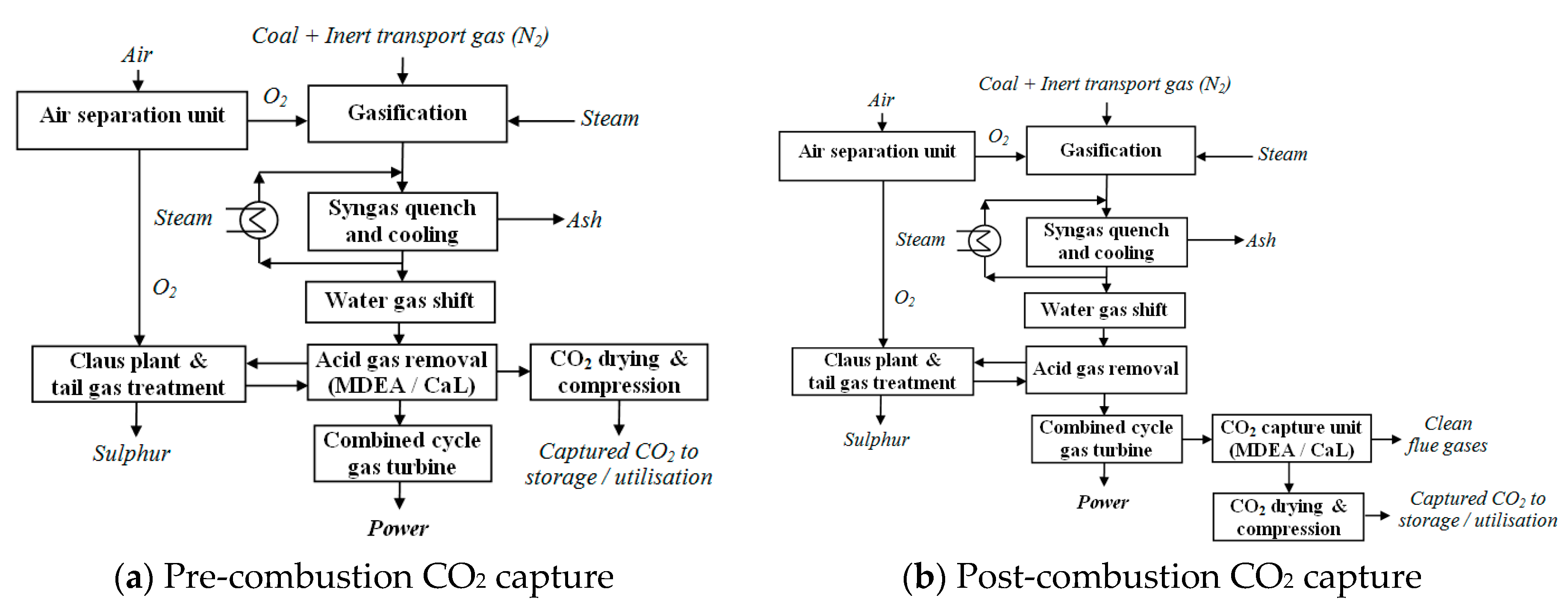
  • Case 1.2—Decarbonized power plant based on the pre-combustion concept using reactive gas-liquid absorption (MDEA);
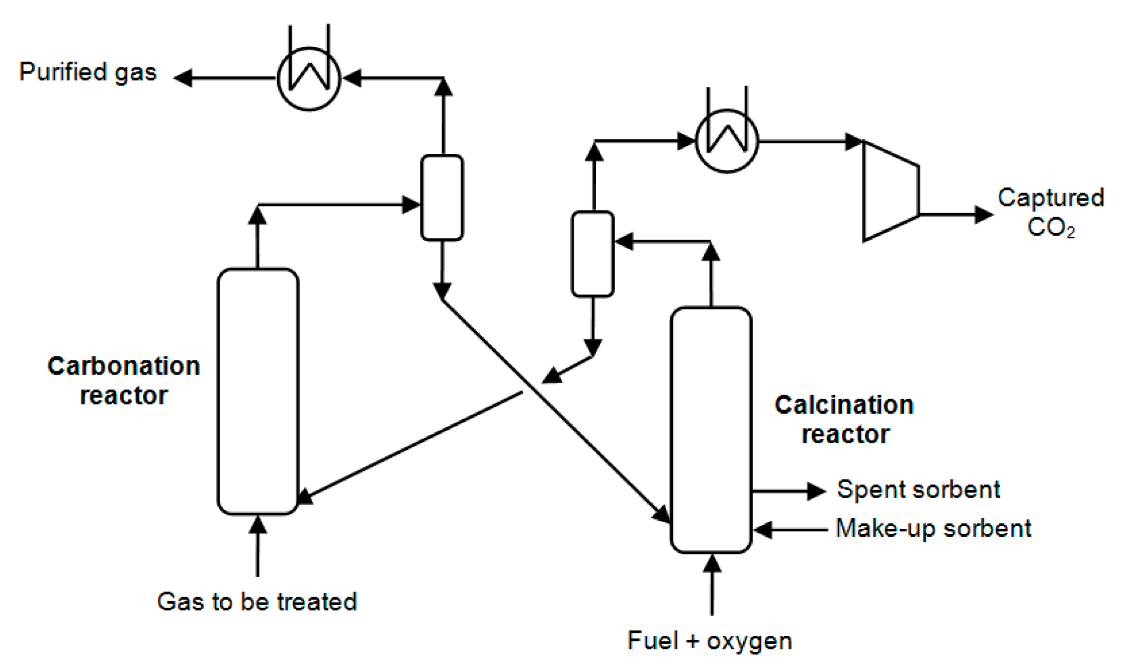
  • Case 1.3—Decarbonized power plant based on the pre-combustion concept using reactive gas-solid system (CaL);
  • Case 1.4—Decarbonized power plant based on the post-combustion concept using reactive gas-liquid absorption (MDEA).
The most important techno-economic and environmental performance indicators of evaluated coal-based gasification power plants are summarized in Table 2.
As shown in Table 2, the pre-combustion capture configurations have a lower decarbonization energy penalty than the post-combustion option (9.3–9.7 vs. 11.7 net energy efficiency percentage points). This energy efficiency difference of about two net percentage points between pre-combustion and post-combustion capture cases can be explained by the significantly higher partial pressure of CO2 in the gas subject to decarbonization (12–14 bar for pre-combustion cases vs. 0.13–0.16 bar for post-combustion cases). For the pre-combustion options, the MDEA concept (Case 1.2) shows higher net efficiency than the CaL concept (Case 1.3).
The specific consumption of primary energy for CO2 avoided (SPECCA indicator) shows slightly better performances for the MDEA system compared to the CaL one (either prior or after combustion). In addition, CaL design (which uses a Circulated Fluidization Bed—CFB system) is more complicated to be adjusted for operation at high pressures (about 30–40 bar) as required in the pre-combustion option [33]. Specific CO2 emissions (carbon footprint) for all decarbonized plants are significantly reduced compared to the benchmark case without carbon capture. A full Life Cycle Analysis (LCA) reveals (as illustrated below in case of super-critical combustion-based power plants) that other environmental impact indicators increase by plant decarbonization [30]. This negative element of process decarbonization is explained by increasing the raw materials consumptions, reducing energy efficiency, and introducing new plant sub-units (CO2 capture and conditioning units).
The decarbonization process of gasification-based power generation brings significant economic penalty (23–75% increase in the specific capital investment, 35–50% increase in the electricity cost). The economic indicators show that pre-combustion capture (either gas-liquid absorption or calcium looping) is definitely better than post-combustion capture in term of specific capital investment (reduced by 20–30%), levelized cost of electricity (reduced by 6–10%) and CO2 avoided cost (reduced by 19–30%). The MDEA-based decarbonization option has slightly better electricity cost, and CO2 avoided cost than the calcium looping option (for the technical reasons mentioned above).
One relevant element to be mentioned here in connection with gasification systems represents the ability of this partial oxidation technology to generate, in a flexible manner, various energy carriers. For instance, after syngas decarbonization in a pre-combustion capture configuration, the hydrogen-rich gaseous stream could be employed for the generation of power, hydrogen, or other synthetic carbon-based fuels (methanol, substitute natural gas, synthetic hydrocarbons via Fischer–Tropsch process). One key advantage of these systems represents high cumulative energy efficiency. This specific design characteristic of gasification-based energy conversion systems represents an important element for the future low carbon higher efficiency systems [34].

5.2. Coal-Based Super-Critical Combustion Power Plants

To quantify the techno-economic and environmental impact of the decarbonization process for the coal-based, super-critical, combustion-based, power generation using post-combustion capture systems, the next power plant concepts were used as illustrative examples in this work:
  • Case 2.1—Conventional combustion-based power plant without decarbonization;
  • Case 2.2—Decarbonized power plant based on reactive gas-liquid absorption (MDEA);
  • Case 2.3—Decarbonized power plant based on reactive gas-solid system (CaL).
The non-capture concept (Case 2.1) is based on current industrial design having 500 MW net output [19]. For the assessed decarbonized concepts (both having the same plant decarbonization degree—90%), the additional heat and power consumptions required for CO2 capture are covered by the main power block. The most important techno-economic and environmental performance indicators of evaluated coal-based super-critical power plants are summarized in Table 3.
As presented in Table 3, the decarbonization penalty for super-critical power plants lays between seven to nine net energy efficiency percentage points (for the same decarbonization rate considered in both options—90%). The post-combustion calcium looping decarbonization system shows improved values in comparison to the chemical gas-liquid absorption scrubbing system. The difference in net power efficiency points for the two decarbonization systems is about 1.62. This value is justified by the high-temperature heat recovery potential of the calcium looping cycle. The specific consumption of primary energy for CO2 avoided (SPECCA) also shows better value for chemical looping in comparison to chemical scrubbing (gas-liquid absorption) by about 0.67 MJ/kg. All these technical and environmental benefits of the CaL-based decarbonization process translate into improved economic performance [35]. All economic indicators are in favor of the calcium looping option in comparison to the gas-liquid absorption as assessed decarbonization technologies—specific investment cost (reduced by about 25%), levelized cost of electricity (reduced by about 18%), and CO2 avoided cost (reduced by about 36%). Also, it worth mentioning that the combustion-based power generation is cheaper than the gasification-based power generation in a non-carbon capture scenario, but when carbon capture is implemented, the economic differences are reduced significantly or even are in favor of IGCC power plants (see Table 2 and Table 3).
To illustrate an in-depth environmental impact evaluation for the assessed super-critical power plants with and without carbon capture, Table 4 presents the Life Cycle Analysis (LCA) results in a cradle-to-grave approach using CML 2001 method. The full technical details of this LCA analysis are presented in the paper indicated as reference [31].
It can be noticed that the carbon footprint (noted here as Global Warming Potential—GWP) is reduced with plant decarbonization (not corresponding to 90% plant decarbonization rate but to a lower rate due to up-stream and down-stream processes). All other environmental indicators are increasing with plant decarbonization; in some cases, the increasing rate is quite high (e.g., acidification potential, indicators related to toxicity, etc.). It worth mention that for the calcium looping system, all environmental indicators have better values than for the reactive gas-liquid absorption system. The main reason for this result represents the lower environmental impact of natural-based calcium sorbent in comparison to a chemical-based solvent.

5.3. Integrated Steel Mills

To assess the techno-economic and environmental impact of decarbonization applied to iron and steel production, the next plant concepts were used as illustrative examples:
  • Case 3.1—Conventional steel mill without decarbonization;
  • Case 3.2—Decarbonized steel mill based on reactive gas-liquid absorption (MDEA);
  • Case 3.3—Decarbonized steel mill based on reactive gas-solid system (CaL).
As presented in Table 1, a conventional integrated iron and steel plant was considered in the assessments with 4 Mt/y hot-rolled coil (HRC) production capacity [3]. All assessed decarbonized steel concepts are not considering any import of heat and power (steel mill off-gases are used for this purpose). In this respect, natural gas was used as additional fuel to cover the ancillary energy consumptions [36]. The decarbonized steel mill concepts capture CO2 from the most significant plant units, e.g., captive power plant, blast furnace hot stoves, and lime coke production units. The most important performances of evaluated steel plants are exhibited in Table 5.
As shown in Table 5, the decarbonization of main CO2 emitters (captive heat and power plant, blast furnace, lime and coke production units) from an integrated iron and steel production plant cut the overall carbon footprint significantly (with a reduction of about 60 to 70%). Considering the significant amount of greenhouse gas emission of this important industrial sector, this reduction is very substantial [36]. The investigated looping cycle has some important advantages in comparison to the chemical scrubbing system, e.g., higher energy conversion yield and subsequent lower decarbonization energy and cost penalties, integration of spent calcium-based sorbent in the iron and steel production process with a positive impact on plant environmental performance [37]. As for the above-presented cases (combustion and gasification-based power generation), the decarbonization process reduces carbon footprint but increases other environmental indicators [36].
Decarbonization of iron and steel production process brings an economic penalty (6–13% increase of specific capital investment, 12–18% increase of steel production cost). The economic indicators show that the calcium looping option has slightly better economic performance than post-combustion capture in terms of specific capital investment (reduced by about 6%), steel production cost (reduced by about 5%), and CO2 avoided cost (reduced by about 6%).

5.4. Cement Plants

To evaluate the impact of process decarbonization (in a post-combustion capture configuration) for cement production, the next plant concepts were considered as illustrative examples:
  • Case 4.1—Conventional cement production plant without decarbonization;
  • Case 4.2—Decarbonized cement production based on reactive gas-liquid absorption (MDEA);
  • Case 4.3—Decarbonized cement production based on reactive gas-solid system (CaL).
As presented in Table 1, a conventional cement plant was considered in the assessments with 1 Mt/y production capacity [4]. For decarbonized cement production cases by reactive gas-liquid and gas-solid systems, a coal-based combustion unit in conjunction with a steam cycle power block was used to cover the ancillary energy (heat and power) consumptions of the carbon capture plants [38]. The excess energy was exported as the power to the grid with a 520 kg/MWh as the carbon dioxide emission factor. The most relevant techno-economic and environmental performance indexes of the assessed cement plants are exhibited in Table 6.
As presented in Table 6, the cement plant decarbonization cut significantly the overall carbon footprint of the process (by about 92–93%). The investigated looping cycle exhibits several benefits in comparison to the chemical scrubbing system, e.g., higher energy conversion yield and subsequent lower decarbonization energy penalty. Another important element of the calcium-based reactive gas-solid system refers to the potential to reuse the spent solid material in the cement plant (clinker production). This element brings advantages in terms of reducing carbon footprint as well as improving technical and economic performance indicators [39]. As for the above-presented cases, the decarbonization process brings a positive effect in reducing the carbon footprint, but on the other hand, increases other environmental indicators [40].
Decarbonization of the cement production process brings significant economic penalty (74–112% increase of specific capital investment, 62–95% increase of cement production cost). The economic indicators show that calcium looping option has better economic performance than post-combustion capture in term of specific capital investment (reduced by about 18%), cement production cost (reduced by about 16%), and CO2 avoided cost (reduced by about 34%).

6. Conclusions

This techno-economic and environmental analysis assessed in a quantifiable manner the decarbonization process of some important fossil-based industrial processes (electricity generation, iron, steel and cement production). As decarbonization technologies, two reactive gas-liquid (chemical scrubbing using alkanolamines—MDEA) and gas-solid (based on calcium-based sorbents) systems were assessed. The CaL decarbonization option exhibits improved performance indicators over the chemical scrubbing for the evaluated post-combustion capture configurations (higher energy conversion yields, lower carbon footprint and specific primary energy consumption, better economic indicators, etc.). In addition, for some of the evaluated processes (steel and cement production plants), the spent solid sorbent from the looping cycle can be utilized by the integration of the whole production chain with positive techno-economic and environmental results. For the pre-combustion capture configuration (evaluated here in relation to a coal gasification plant), the chemical scrubbing by gas-liquid absorption shows higher energy efficiency and more potential for future developments than CaL decarbonization option. Regarding the environmental impact of the LCA analysis, it is worth mentioning that the carbon footprint is reduced by the process decarbonization, but other environmental indicators show significant increases. To illustrate this element, the results of an LCA analysis were presented in detail for super-critical combustion-based power plant concepts.

Author Contributions

A.-M.C., L.P. and C.-C.C. did the model conceptualization of evaluated systems and proposed the assessing methodology, A.-M.C., S.D. and C.-C.C. assessed the main technical and environmental performances, V.S. and C.-C.C. were responsible with modeling, simulation and Heat Integration work as well as writing the paper. All authors have read and agreed to the published version of the manuscript.

Funding

This research received no external funding.

Conflicts of Interest

The authors declare no conflict of interest.

References

  1. European Commission. The European Green Deal; COM(2019) 640 Final; European Commission: Brussels, Belgium, 2019. [Google Scholar]
  2. International Energy Agency. Global Energy & CO2 Status Report 2019. Available online: https://www.iea.org/reports/global-energy-and-co2-status-report-2019/emissions (accessed on 7 January 2020).
  3. International Energy Agency—Greenhouse Gas R&D Programme. Iron and Steel CCS Study (Techno-Economic Integrated Steel Mill); Report 2013/04; IEAGHG: Cheltenham, UK, 2013. [Google Scholar]
  4. International Energy Agency—Greenhouse Gas R&D Programme. Deployment of CCS in the Cement Industry; Report 2013/19; IEAGHG: Cheltenham, UK, 2013. [Google Scholar]
  5. European Commission. A Policy Framework for Climate and Energy in the Period From 2020 to 2030; COM(2014) 15 Final; European Commission: Brussels, Belgium, 2014. [Google Scholar]
  6. Metz, B.; Davidson, O.; Coninck, H.; Loos, M.; Meyer, L. Special Report: Carbon Dioxide Capture and Storage; Intergovernmental Panel on Climate Change (IPCC); Cambridge University Press: New York, NY, USA, 2005. [Google Scholar]
  7. Norhasyima, R.S.; Mahlia, T.M.I. Advances in CO₂ utilization technology: A patent landscape review. J CO2 Util. 2018, 26, 323–335. [Google Scholar] [CrossRef]
  8. Fang, M.; Yi, N.; Di, W.; Wang, T.; Wang, Q. Emission and control of flue gas pollutants in CO2 chemical absorption system—A review. Int. J. Greenh. Gas Con. 2020, 93, 102904. [Google Scholar] [CrossRef]
  9. Fan, L.S. Chemical Looping Systems for Fossil Energy Conversions; Wiley-AIChE: Hoboken, NJ, USA, 2010. [Google Scholar]
  10. Borhani, T.N.; Wang, M. Role of solvents in CO2 capture processes: The review of selection and design methods. Renew. Sustain. Energy Rev. 2019, 114, 109299. [Google Scholar] [CrossRef]
  11. Cormos, A.M.; Dinca, C.; Cormos, C.C. Energy efficiency improvements of post-combustion CO2 capture based on reactive gas-liquid absorption applied for super-critical circulating fluidized bed combustion (CFBC) power plants. Clean. Technol. Environ. 2018, 20, 1311–1321. [Google Scholar] [CrossRef]
  12. Li, T.; Keener, T.C. A review: Desorption of CO2 from rich solutions in chemical absorption processes. Int. J. Greenh. Gas Con. 2016, 51, 290–304. [Google Scholar] [CrossRef]
  13. Cormos, A.M.; Cormos, C.C. Techno-economic assessment of combined hydrogen & power co-generation with carbon capture: The case of coal gasification. Appl. Therm. Eng. 2019, 147, 29–39. [Google Scholar]
  14. Yan, Y.; Wang, K.; Clough, P.T.; Anthony, E.J. Developments in calcium/chemical looping and metal oxide redox cycles for high-temperature thermochemical energy storage: A review. Fuel Process. Technol. 2020, 199, 106280. [Google Scholar] [CrossRef]
  15. Hornberger, M.; Spörl, R.; Scheffknecht, G. Calcium Looping for CO2 Capture in Cement Plants—Pilot Scale Test. Energy Procedia 2017, 114, 6171–6174. [Google Scholar] [CrossRef]
  16. Cormos, C.C. Economic evaluations of coal-based combustion and gasification power plants with post-combustion CO2 capture using calcium looping cycle. Energy 2014, 78, 665–673. [Google Scholar] [CrossRef]
  17. Higman, C.; van der Burgt, M. Gasification, 2nd ed.; Gulf Professional Publishing, Elsevier Science: Burlington, MA, USA, 2008. [Google Scholar]
  18. International Energy Agency—Greenhouse Gas R&D Programme. Potential for Improvement in Gasification Combined Cycle Power Generation with CO2 Capture; Report PH4/19; IEAGHG: Cheltenham, UK, 2003. [Google Scholar]
  19. National Energy Technology Laboratory. Cost and Performance Baseline for Fossil Energy Plants, Volume 1: Bituminous Coal and Natural Gas to Electricity; Report 2010/1397; NETL: Albany, NY, USA, 2010. [Google Scholar]
  20. Ramírez-Santos, A.A.; Castel, C.; Favre, E. A review of gas separation technologies within emission reduction programs in the iron and steel sector: Current application and development perspectives. Sep. Purif. Technol. 2018, 194, 425–442. [Google Scholar]
  21. Quader, M.A.; Ahmed, S.; Ghazilla, R.A.; Ahmed, S.; Dahari, M. A comprehensive review on energy efficient CO2 breakthrough technologies for sustainable green iron and steel manufacturing. Renew. Sustain. Energy Rev. 2015, 50, 594–614. [Google Scholar] [CrossRef]
  22. Cormos, A.M.; Dinca, C.; Petrescu, L.; Chisalita, D.A.; Szima, S.; Cormos, C.C. Carbon capture and utilisation technologies applied to energy conversion systems and other energy-intensive industrial applications. Fuel 2018, 211, 883–890. [Google Scholar] [CrossRef]
  23. Garcia, M.; Berghout, N. Toward a common method of cost-review for carbon capture technologies in the industrial sector: Cement and iron and steel plants. Int. J. Greenh. Gas Con. 2019, 87, 142–158. [Google Scholar] [CrossRef]
  24. Manan, Z.A.; Nawi, W.N.R.M.; Alwi, S.R.W.; Klemeš, J.J. Advances in Process Integration research for CO2 emission reduction—A review. J. Clean. Prod. 2017, 167, 1–13. [Google Scholar] [CrossRef]
  25. Perejón, A.; Romeo, L.M.; Lara, Y.; Lisbona, P.; Martínez, A.; Valverde, J.M. The Calcium-Looping technology for CO2 capture: On the important roles of energy integration and sorbent behavior. Appl. Energy 2016, 162, 787–807. [Google Scholar]
  26. International Energy Agency—Greenhouse Gas R&D Programme. Improvement in Power Generation with Post-Combustion Capture of CO2; Report no. PH4/33; IEAGHG: Cheltenham, UK, 2004. [Google Scholar]
  27. Sun, H.; Wu, C.; Shen, B.; Zhang, X.; Zhang, Y.; Huang, J. Progress in the development and application of CaO-based adsorbents for CO2 capture—A review. Mater. Today Sustain. 2018, 1–2, 1–27. [Google Scholar] [CrossRef]
  28. Haaf, M.; Peters, J.; Hilz, J.; Unger, A.; Ströhle, J.; Epple, B. Combustion of solid recovered fuels within the calcium looping process—Experimental demonstration at 1 MWth scale. Exp. Therm. Fluid Sci. 2020, 113, 110023. [Google Scholar] [CrossRef]
  29. International Energy Agency—Greenhouse Gas R&D Programme. The IEAGHG Power Plant Assessment Program (PPAP); Report 2005/7; IEAGHG: Cheltenham, UK, 2005. [Google Scholar]
  30. Petrescu, L.; Cormos, C.C. Environmental assessment of IGCC power plants with pre-combustion CO2 capture by chemical & calcium looping methods. J. Clean. Prod. 2017, 158, 233–244. [Google Scholar]
  31. Petrescu, L.; Bonalumi, D.; Valenti, G.; Cormos, A.M.; Cormos, C.C. Life Cycle Assessment for supercritical pulverized coal power plants with post-combustion carbon capture and storage. J. Clean. Prod. 2017, 157, 10–21. [Google Scholar] [CrossRef]
  32. Petrescu, L.; Chisalita, D.A.; Cormos, C.C.; Manzolini, G.; Cobden, P.; van Dijk, H.A.J. Life Cycle Assessment of SEWGS technology applied to integrated steel plants. Sustainability 2019, 11, 1825. [Google Scholar] [CrossRef] [Green Version]
  33. Diego, M.E.; Arias, B. Impact of load changes on the carbonator reactor of a 1.7 MWth calcium looping pilot plant. Fuel Process. Technol. 2020, 200, 106307. [Google Scholar] [CrossRef]
  34. Cormos, A.M.; Dinca, C.; Cormos, C.C. Multi-fuel multi-product operation of IGCC power plants with carbon capture and storage (CCS). Appl. Therm. Eng. 2015, 74, 20–27. [Google Scholar] [CrossRef]
  35. Rolfe, A.; Huang, Y.; Haaf, M.; Rezvani, S.; MclIveen-Wright, D.; Hewitt, N.J. Integration of the calcium carbonate looping process into an existing pulverized coal-fired power plant for CO2 capture: Techno-economic and environmental evaluation. Appl. Energy 2018, 222, 169–179. [Google Scholar] [CrossRef]
  36. Chisalita, D.A.; Petrescu, L.; Cobden, P.; van Dijk, H.A.J.; Cormos, A.M.; Cormos, C.C. Assessing the environmental impact of an integrated steel mill with post-combustion CO2 capture and storage using the LCA methodology. J. Clean. Prod. 2019, 211, 1015–1025. [Google Scholar] [CrossRef]
  37. Nidheesh, P.V.; Kumar, M.S. An overview of environmental sustainability in cement and steel production. J. Clean. Prod. 2019, 231, 856–871. [Google Scholar] [CrossRef]
  38. Dean, C.C.; Blamey, J.; Florin, N.H.; Al-Jeboori, M.J.; Fennell, P.S. The calcium looping cycle for CO2 capture from power generation, cement manufacture and hydrogen production. Chem. Eng. Res. Des. 2011, 89, 836–855. [Google Scholar] [CrossRef] [Green Version]
  39. Erans, M.; Jeremias, M.; Zheng, L.; Yao, J.G.; Blamey, J.; Manovic, V.; Fennell, P.S.; Anthony, E.J. Pilot testing of enhanced sorbents for calcium looping with cement production. Appl. Energy 2018, 225, 392–401. [Google Scholar] [CrossRef]
  40. Kuramochi, T.; Ramírez, A.; Turkenburg, W.; Faaij, A. Comparative assessment of CO2 capture technologies for carbon-intensive industrial processes. Prog. Energy Combust. Sci. 2012, 38, 87–112. [Google Scholar] [CrossRef]
Figure 1. CO2 capture by chemical scrubbing via an absorption-desorption cycle.
Energies 13 01268 g001
Figure 2. CO2 capture by the calcium-based sorbent looping cycle.
Energies 13 01268 g002
Figure 3. Decarbonized Integrated Gasification Combined Cycle (IGCC) power plant options.
Energies 13 01268 g003
Figure 4. Decarbonized super-critical power plant.
Energies 13 01268 g004
Figure 5. Decarbonized integrated steel mill.
Energies 13 01268 g005
Figure 6. Decarbonized cement plant.
Energies 13 01268 g006
Figure 7. Calcium looping cycle Heat Integration analysis.
Energies 13 01268 g007
Table 1. Main design elements of evaluated decarbonized industrial processes.
Unit Design Assumptions
Fossil fuel (coal) specifications [22]Ultimate analysis (dry weight percentages): 72.30% carbon, 4.11% hydrogen, 1.69% nitrogen, 7.45% oxygen, 0.56% sulfur, 13.89% ash; Moisture: 8%; Lower heating value: 25.17 MJ/kg
Gasification power plant [12]Entrained-flow gasifier with syngas quench
Separate H2S and CO2 removal by absorption and adsorption systems
Combined cycle power using one M701G2 gas turbine
Super-critical power plant [17]290 bar/582 °C and two reheats at 75 bar/580 °C and 20 bar/580 °C
95% NOx removal yield by selective catalytic reduction unit
98–99% SOx removal yield by wet desulphurization unit
Integrated steel mill [3]Plant capacity: 4 Mt/y hot-rolled coil (HRC)
Decarbonization of power plant, hot stoves, lime and coke production
Natural gas-based heat and power unit for ancillary consumptions
Captive heat and power plant: subcritical boiler and combined cycle
Cement plant [4]Plant capacity: 1 Mt/y cement
95% NOx removal yield by selective catalytic reduction unit
98–99% SOx removal yield by wet desulphurization unit
Coal-based heat and power unit for ancillary energy consumptions
Decarbonization unit employing a chemical scrubbing system [19]Methyl-diethanol-amine (MDEA) aqueous solution 50% wt.
Absorption/desorption columns: 42–55 °C/115–125 °C
90% flue gas decarbonization rate (pre- and post-combustion)
Solvent regeneration: thermal using LP steam at 140–150 °C
Decarbonization unit employing a Ca-based sorbent system [19]Natural limestone as calcium-based sorbent
Carbonation/calcination reactors: 540–615 °C/825–975 °C
90% flue gas decarbonization rate (pre- and post-combustion)
Oxy-fuel combustion system to provide heat for sorbent regeneration
Power consumption for oxygen production unit: 200 kWh/t
CO2 conditioning unit [14]Four compression stages with 120 bar final pressure at plant gate
Moisture removal by gas-liquid absorption using Tri-Ethylene-Glycol (TEG)
CO2 composition (volume percentages): >95% CO2, <2000 ppm CO, <200 ppm H2O,<50 ppm H2S, <4% other gases
Table 2. Gasification power plants techno-economic and environmental performance indexes.
Performance IndexUMCase 1.1Case 1.2Case 1.3Case 1.4
Fossil fuel (coal) consumptiont/h151.00166.80222.00228.17
Coal lower heating value (LHV)MJ/kg25.17
Power plant input thermal energyMW1055.741166.211552.151595.30
Power output (combined cycle)MW560.61535.88716.25720.50
Power consumptionMW76.25108.91156.18175.01
Net power outputMW484.36426.97560.07545.49
Net power efficiency%45.8736.6136.0834.19
Plant decarbonization rate%0.0090.0090.0090.00
Specific power plant emissionskg/MWh760.2585.4883.0288.95
SPECCAMJ/kg-2.943.143.99
Specific capital investment€/kW1874.002620.002305.003286.00
Levelised cost of electricity€/MWh54.1373.2876.0781.25
CO2 avoided cost€/t-28.3832.4040.39
Table 3. Super-critical power plants techno-economic and environmental performance indexes.
Performance IndexUMCase 2.1Case 2.2Case 2.3
Fossil fuel (coal) consumptiont/h165.00208.50199.13
Coal lower heating value (LHV)MJ/kg25.17
Power plant input thermal energyMW1153.621457.761392.24
Power output (steam turbine)MW528.90569.05596.81
Power consumptionMW28.9069.0596.81
Net power outputMW500.00500.00500.00
Net power efficiency%43.3434.3035.92
Plant decarbonization rate%0.0090.0090.00
Specific power plant emissionskg/MWh800.6189.6077.05
SPECCAMJ/kg-3.082.41
Specific capital investment€/kW1320.002520.001875.00
Levelised cost of electricity€/MWh45.5384.0268.41
CO2 avoided cost€/t-49.0931.34
Table 4. Environmental impact indicators (Life Cycle Analysis) for super-critical power plants.
Environmental Impact IndexUMCase 2.1Case 2.2Case 2.3
Global warming potentialkg CO2 eq./MWh970.37495.93402.20
Acidification potentialkg SO2 eq./MWh0.494.571.66
Eutrophication potentialkg PO4−3 eq./MWh1285.441739.761121.86
Ozone depletion potential ×108kg R11 eq./MWh0.594.072.63
Abiotic depletion potentialMJ/MWh9829.2815,231.6313,752.06
Freshwater ecotoxicity potentialkg DCB eq./MWh0.271.661.10
Human toxicity potentialkg DCB eq./MWh3.4155.2719.84
Photochemical oxidation potentialkg Ethene eq./MWh0.202.710.26
Terrestrial ecotoxicity potentialkg DCB eq./MWh0.050.280.18
Marine ecotoxicity potentialkg DCB eq./MWh6730.5426,011.8516,494.81
Table 5. Integrated steel mills techno-economic and environmental performance indexes.
Performance IndexUMCase 3.1Case 3.2Case 3.3
Fossil fuel (natural gas) consumptionMW669.80544.001156.80
Power output (gas turbine)MW-202.3191.06
Power output (steam turbine)MW224.68107.33366.06
Gross power block outputMW224.68309.65457.12
Power consumptionMW9.681.68132.65
Net power block outputMW215.00307.97324.47
Net power block efficiency%32.1056.6128.04
Decarbonization rate (power block)%0.000.0090.00
Specific CO2 emissions (power)kg/MWh2455.42370.02242.32
Specific CO2 emissions (steel)kg/t HRC980.48229.50166.10
Decarbonization rate (capture plant)%0.0090.0090.00
Overall plant specific CO2 emissionskg/t HRC2092.50833.55640.00
Quantity of captured CO2kg/t HRC0.001615.801495.20
Specific capital investment€/t HRC955.001077.001015.00
Levelised cost of steel€/t HRC520.73614.05580.70
CO2 avoided cost€/t-73.4668.92
Table 6. Cement plants techno-economic and environmental performance indexes.
Performance IndexUMCase 4.1Case 4.2Case 4.3
Fossil fuel (coal) consumptiont/h-33.5022.10
Coal inferior calorific valueMJ/kg25.17
Thermal energy (decarbonization unit)MW-234.22154.51
Power output (steam turbine)MW-54.4058.12
Gross power block outputMW-54.4058.12
Power consumptionMW16.2434.1642.38
Net power block outputMW-20.2415.74
Net power block efficiency%-8.6410.18
Plant decarbonization rate%0.0090.0090.00
Specific plant CO2 emissions (on-site)kg/t cement728.42135.78120.74
Specific plant CO2 emissions (export)kg/t cement42.02−79.93−62.35
Specific plant CO2 emissions (total)kg/t cement770.4455.8558.39
Quantity of captured CO2kg/t cement0.001214.17962.20
Specific capital investment€/t cement263.00557.00458.00
Levelized cost of cement€/t cement65.60127.68106.73
CO2 avoided cost€/t-86.8757.76

