Article

Flexible Kinetic Energy Release Controllers for a Wind Farm in an Islanding System

Department of Electrical Engineering, National Taiwan University, EE Building 2, No. 1, Sec. 4, Roosevelt Rd., Taipei 106, Taiwan
*
Author to whom correspondence should be addressed.
Energies 2020, 13(22), 6135; https://doi.org/10.3390/en13226135
Submission received: 23 October 2020 / Revised: 18 November 2020 / Accepted: 19 November 2020 / Published: 23 November 2020

Abstract

:
To improve frequency nadir following a disturbance and avoid under-frequency load shedding, two types of flexible kinetic energy release controllers for the doubly fed induction generator (DFIG) are proposed. The basic idea is to release only a small amount of kinetic energy stored at the DFIG in the initial transient period (1–3 s after the disturbance). When the frequency dip exceeds a preset threshold, the amount of kinetic energy released is increased to improve the frequency nadir. To achieve the goal of flexible kinetic energy release, a deactivation function based integral controller is first presented. To further improve the dynamic frequency response under parameter uncertainties and external disturbances, a second flexible kinetic energy release controller is designed using a proportional-integral controller, with the gains being adapted in real-time with the particle swarm optimization algorithm. Based on the MATLAB/SIMULINK simulation results for a local power system, it is concluded that the frequency nadir can be maintained around the under-frequency load shedding threshold of 59.6 Hz using the proposed controllers.

1. Introduction

To improve the dynamic frequency response of a local power system with high penetration of wind power, a supplementary frequency controller (SFC) installed on the rotor side converter (RSC) of a doubly fed induction generator (DFIG) has been widely investigated in recent years. The main purpose of this work is to design a proper SFC such that the frequency nadir (FN) of the islanding system following a grid disconnection event can be maintained higher than the threshold of 59.6 Hz, which is equal to the sum of the low frequency load shedding limit of 59.5 Hz set by the local utility and 0.1 Hz safety margin. In other words, frequency nadir following a disturbance causing a power deficit is of major concern in this paper.
In the literature, a proportional (droop) controller which generates a control signal proportional to the frequency deviation has been proposed [1,2,3,4,5,6,7,8,9,10]. When the control signal is added to the RSC of the DFIG, the electrical power output of the DFIG can be modulated and the system frequency response can be improved. To further improve the dynamic frequency response, the gain of the proportional controller was varied based on the rate of change of frequency (ROCOF) [4], or DFIG rotor speed [5]. In [7], the gain was decreased linearly with time. In [8], the particle swarm optimization (PSO) technique was employed to adapt the proportional gain in real-time in order to have a good dynamic frequency response following a disturbance. Other self-tuning techniques such as artificial neural networks [11], model predictive controllers [12,13,14,15], and fuzzy set algorithm [16,17,18] have been proposed to provide the required supplementary frequency control signal.
A proportional (droop)-derivative (inertia) (PD) controller with the inertial control signal being proportional to the derivative of frequency deviation has also been widely studied [19,20,21,22,23,24,25,26,27,28]. The effect of the PD controller on the initial ROCOF [22,24] or frequency nadir [22] has been examined. It was pointed out in [7,22] that the initial ROCOF might be improved during the inertia period (around 1–2 s after the disturbance) by the inertia controller through injecting more DFIG electrical power to the power system. However, the inertia control might have a negative impact on frequency nadir since the DFIG injects more electrical power to reach a smaller frequency dip, causing the steam or gas turbine to deliver less mechanical power to the synchronous generator (SG). The increase in DFIG kinetic energy release and reduction in SG accumulated mechanical energy in the first few seconds might cause a lower frequency nadir in the subsequent primary frequency regulation period (around 2–50 s after the disturbance). Therefore, the optimal inertia controller gain to have the highest frequency nadir was found to be close to zero [22]. Therefore, the inertia control will not be considered in this work, since our goal is to reach the highest frequency nadir to avoid under-frequency load shedding.
In this paper, two flexible kinetic energy release controllers for a DFIG wind farm are proposed in order to improve the frequency nadir after a disturbance. The basic idea is to release less kinetic energy from the DFIG during the first few seconds after the disturbance when the system frequency is above a certain threshold. When the system frequency drops to a level below the threshold, the kinetic energy reserved in the DFIG during the first few seconds after the disturbance is gradually released to improve the frequency nadir.
In the first flexible kinetic energy release controller, an integral controller is added to the conventional droop controller when the system frequency is lower than 59.9 Hz. A deactivation function is proposed to gradually decrease the integral controller output to zero and force the DFIG to return to its steady-state maximum power point tracking (MPPT) operating mode when the system frequency eventually returns to its nominal value of 60 Hz.
The gains in the first flexible kinetic energy release controller are designed based on a particular operating point. To improve the dynamic frequency response for the system subject to variations in system parameters such as speed governor and steam turbine time constants or external disturbances such as wind speed variation, the second flexible kinetic energy release controller, in which the controller gains are adapted in real-time based on PSO algorithm, is proposed. The advantages and disadvantages of the proposed controllers and controllers referred to in the literature are summarized in Table 1.

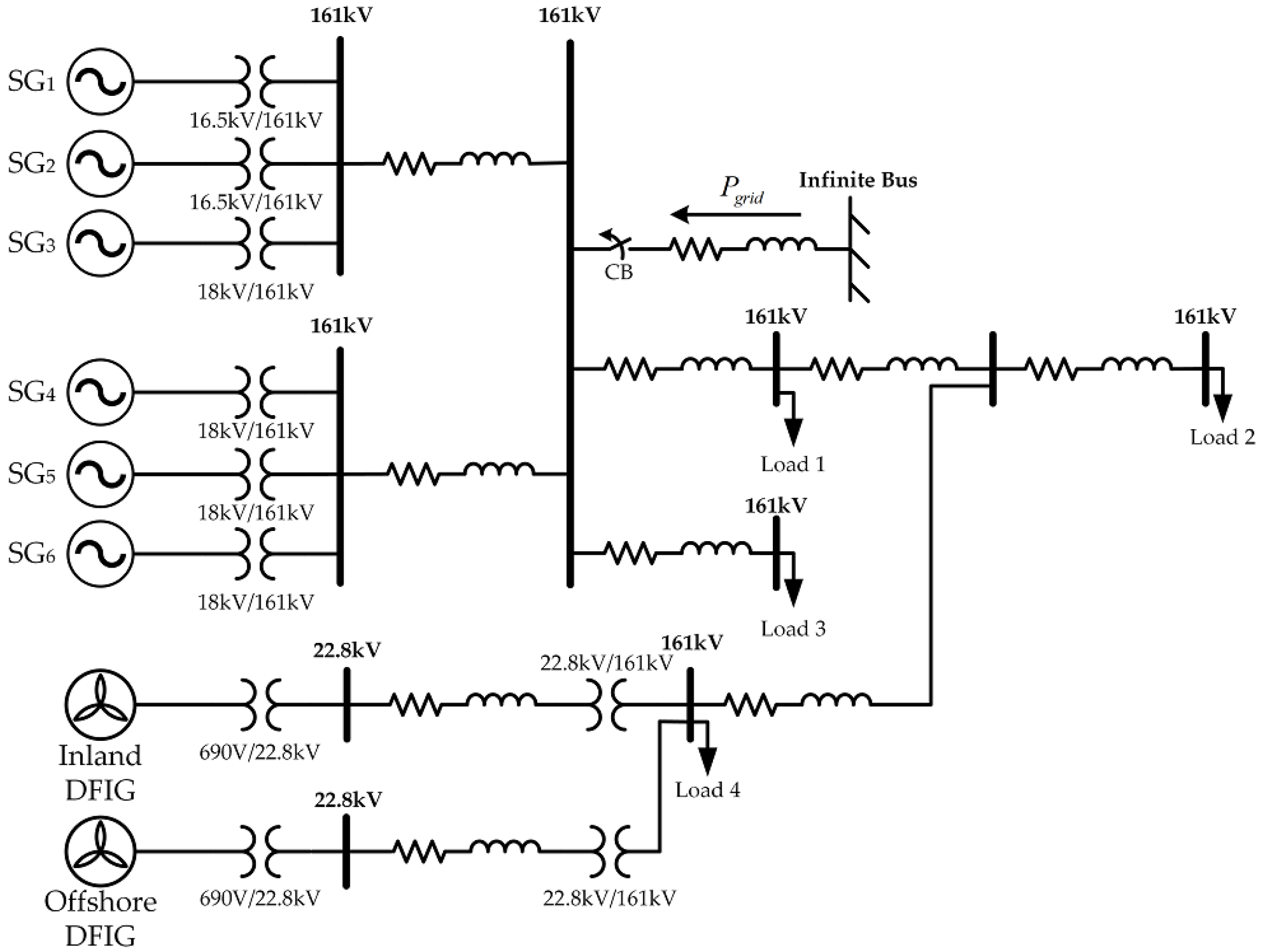
2. Test System Model

The test system under study is a local power system as illustrated in Figure 1.
The six synchronous generators in the local power system in Figure 1 are lumped together as an equivalent SG [29] and the inland and offshore wind farms are lumped together as an equivalent DFIG in this study [1]. When the grid is subject to a fault, the local power system is disconnected from the grid and is operated at an islanding operation mode. The functional block diagram for the equivalent SG and equivalent DFIG frequency control system is depicted in Figure 2.
To avoid considerable revenue losses, the approaches of power reserve such as pitch angle control and de-loaded operating strategy are not considered in this work. Therefore, the DFIG operates at the MPPT mode in a normal operation to achieve the maximum harvest of the wind power. The DFIG electromagnetic torque under the MPPT mode is expressed as:
T eD   = T eD , opt
where T eD , opt is the optimum electromagnetic torque for MPPT, which is a quadratic function of the DFIG rotor speed ω mD . In the case of frequency drop due to grid disconnection, the DFIG kinetic energy is the only energy source from a wind farm that can be released to the system. To improve the dynamic response of system frequency, a supplementary frequency control signal from the flexible kinetic energy release controller T FKERC is added to T eD , opt to obtain the desired electromagnetic torque command of the DFIG as shown below:
T eD   =   T eD , opt + T FKERC
In this work, the main purpose of the DFIG flexible kinetic energy release controller is to inject additional real power into the islanding system such that the system frequency nadir is as high as possible during the entire post-disturbance transient period. Due to the fast reaction of the RSC, the frequency response is dominated initially by DFIG. As mentioned earlier, the flexible kinetic energy release controller should be designed for the DFIG to release minimal kinetic energy in the initial transient period. Then, the reserved kinetic energy of the DFIG can be released afterwards to improve the frequency nadir. Details on the design of the two types of flexible kinetic energy release controllers proposed in this work are described in Section 3 and Section 4.

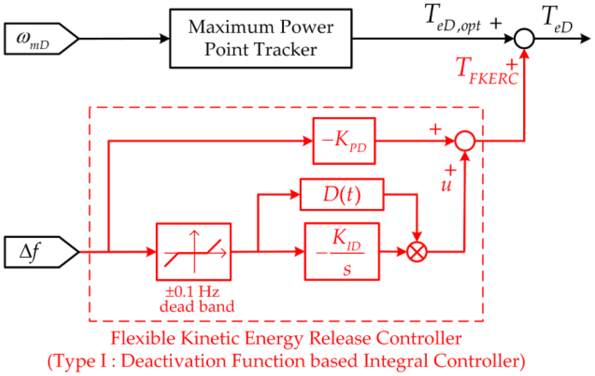
3. Type I Flexible Kinetic Energy Release Controller Using the Deactivation Function Based Integral Controller

In this section, an innovative Type I flexible kinetic energy release controller, as depicted in Figure 3, is proposed to release the kinetic energy flexibly and effectively from a DFIG wind farm.
As shown in Figure 3, the Type I flexible kinetic energy release control signal T FKERC from the deactivation function based integral controller can be written as:
T FKERC   =   { K PD Δ f ( t ) ,   if   f   >   59.9   Hz ( K PD   +   D ( t ) K ID s ) Δ f ( t ) , otherwise
In order for the DFIG to deliver only a small amount of kinetic energy in the initial transient period, only the droop control is employed in Equation (3) when f > 59.9 Hz. When the system frequency is below 59.9 Hz, the deactivation function based integral controller is started. With the proposed Type I flexible kinetic energy release controller, an integral control signal u is gradually increased such that the goal to have a smaller control signal T FKERC in the beginning and a larger control signal afterwards can be met. Therefore, the system frequency nadir can be improved through the action of an integral gain with a deferred and accumulated control output.
Since the integral controller output will not be zero after the transient period is over, the DFIG may work at an operating point which is different from that before the disturbance. For the DFIG to return to its MPPT mode operation when the system frequency approaches its nominal value, the integral controller output must be gradually decreased to zero. In the present work, a deactivation function D(t), as depicted in Figure 4, is proposed to gradually decrease the integral control output to zero in a very smooth manner.
As shown in Figure 4, the integral controller output must be gradually decayed to zero in a period of decay time ( t 2 ) after a delay time ( t 1 ) from the instant of the lowest system frequency (the nadir time t n ). The dynamic frequency response curves for different delay times ( t 1 ) and decay times ( t 2 ) are shown in Figure 5a,b, respectively, for the case of V w = 11 m/s and P grid = 30 MW at t = 10 s.
It is observed from Figure 5a that, after a brief period of frequency rise, the system frequency will drop again to a new low value when the integral controller output is gradually decreased to zero. The decay time t 2 is chosen to be 20 s, and the PI controller gains are K PD = 20 and K ID = 1.5 in Figure 5a. As shown from the response curves in Figure 5a, the delay time t 1 should be kept as small as possible in order to decrease the subsequent frequency drop. This is due to the fact that a longer delay time will cause a greater drop in the DFIG kinetic energy and a lower system frequency following the removal of the integral controller. In the present work, a delay time of 1 s is chosen for t 1 to cover the time required to detect the system frequency nadir.
Figure 5b compares the frequency responses for different decay times t 2 . The PI controller gains are chosen to be K PD = 20 and K ID = 1.5. It is observed that the system frequency after the decay of the integral controller output dips to a value even lower than the first nadir when a short decay time t 2 = 10 s is employed. This is due to the fact that the DFIG output power is decreased rapidly and the SG does not have enough time to increase its output power, causing a power deficit and subsequent frequency dip. On the other hand, the DFIG kinetic energy will be consumed too much, causing a later frequency drop if a long decay time such as t 2 = 50 s is used. In the present work, a moderate decay time t 2 = 20 s is employed.
Since it takes a long time to get a solution from MATLAB/SIMULINK circuit-level simulations, system-level simulations are conducted to approximately estimate the effects of integral controller gains K ID on the system frequency nadir under different values of K PD for the system subject to a disturbance of P grid = 45 MW at t = 10 s, as depicted in Figure 6.
An observation of Figure 6 reveals that a higher frequency nadir can be achieved for the four different values of K PD when a moderate gain of K ID is employed. Table 1 lists the highest frequency nadir for various combinations of K PD and K ID under different values of P grid .
It is observed from Table 2 that a combination of K PD = 20 and K ID = 1 gives the highest frequency nadir for the base case of P grid = 45 MW. The preliminary gains of K PD = 20 and K ID = 1 from system-level simulations are further refined to be K PD = 20 and K ID = 1.1 using more time-consuming circuit-level simulations. In Section 5, the pair of gains K PD = 20 and K ID = 1.1 will be employed for the simulations.

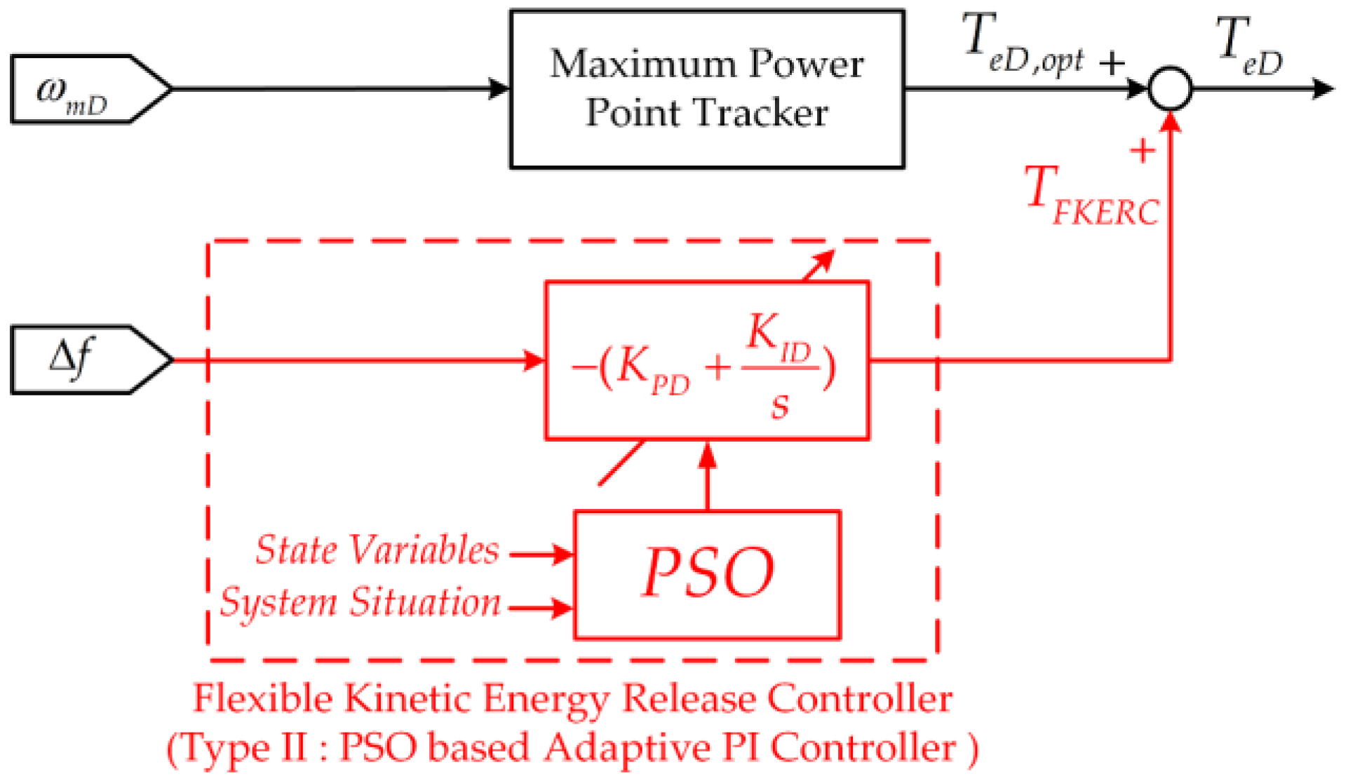
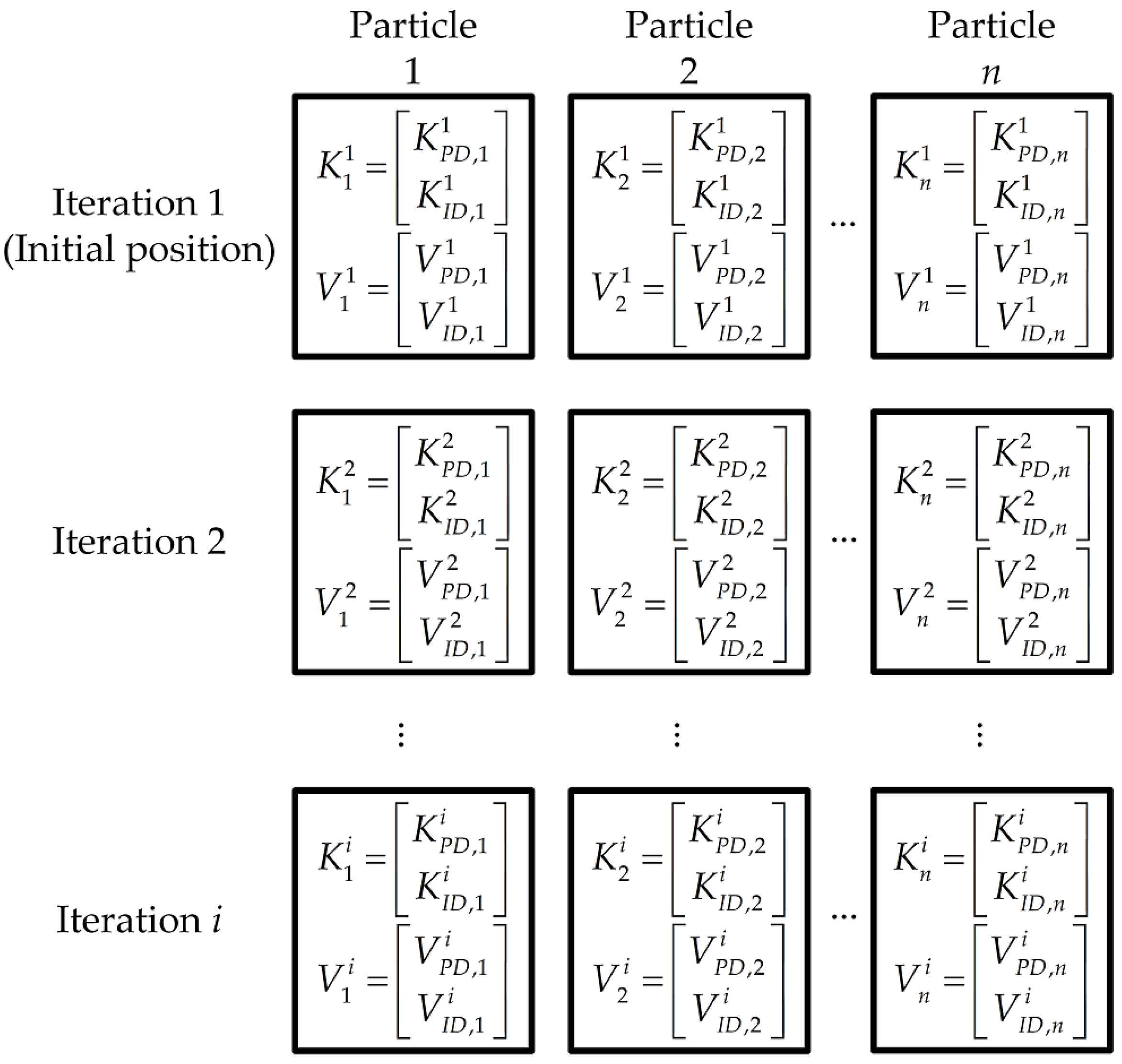
4. Type II Flexible Kinetic Energy Release Controller Using PSO

In the design of Type I flexible kinetic energy release controller, the controller gains are designed based on a certain set of system parameters and operating conditions in order to have a good frequency response under that particular operating point. However, the dynamic frequency response may become unsatisfactory when there is a change in system parameters or operating conditions. In order to have a good frequency response when the system is subject to variations in system parameters or operating conditions, the gains of the Type I flexible kinetic energy release controller may be adapted in real-time using the Type II PSO controller, as shown in Figure 7.
The procedures followed by the proposed flexible kinetic energy release controller using PSO to adjust the controller gains have been described in [30,31]. As shown in Figure 8, in each iteration i, particle n has positions K n i = [ K PD , n i K ID , n i ] T and velocities V n i = [ V PD , n i V ID , n i ] T . The positions and velocities are updated as follows:
K n i + 1   =   K n i + V n i + 1
V n i + 1   =   w n i V n i + r 1 ( K n ( pbest ) K n i ) + r 2 ( K ( gbest ) K n i )
where r 1 and r 2 are random numbers between 0 and 1, K n ( pbest ) is the best particle position, K ( gbest ) is the best global position, and w n i is a weighting factor expressed as:
w n i   =   w MAX ( w MAX w min ) N i
The number of particles N is chosen to be 12 and the total number of iterations is 15. The maximum and minimum values for the weight of the velocity vector are chosen to be w MAX = 0.5 and w min = 0.1, respectively. In this work, the evaluation function E in the PSO algorithm is defined as follows:
E   =   MAX | Δ f pu ( t ) |     Δ f pu *
where Δ f pu ( t ) = f pu ( t ) 1 pu and Δ f pu * = 1 (59.6/60) pu. Note that the PSO algorithm is started only when the system frequency is lower than 59.6 Hz and the evaluation function is chosen to keep the system frequency as close to 59.6 Hz as possible. In this way, the retained DFIG kinetic energy can be released in critical conditions to avoid under-frequency load shedding.

5. Simulation Results

To demonstrate the effectiveness of the proposed flexible kinetic energy release controllers, the local power system in Figure 1 with the parameters in the Appendix A was simulated using MATLAB/SIMULINK. The dynamic responses from detailed circuit-level simulations are presented as follows.

5.1. Dynamic Performance of Type I Flexible Kinetic Energy Release Controller

To examine the dynamic performance of the Type I flexible kinetic energy release controller, dynamic response curves for the following three cases are depicted in Figure 9 under the condition of K PD = 20, P grid = 45 MW, and V w = 11 m/s:
  • Case 1: Droop control only (KID = 0).
  • Case 2: Type I controller with KID = 1.1.
  • Case 3: Type I controller with KID = 2.
The local power system was disconnected from the main grid at the instant of t = 10 s and remained in islanding operation afterwards. The power deficit of 45 MW immediately following the grid disconnection caused a frequency dip, which should be controlled by increasing the DFIG electrical power P eD in order to present the frequency from dropping to a level lower than the under-frequency load shedding threshold of 59.6 Hz.
On comparing the response curves for the three cases in Figure 9, the following observations are in order:
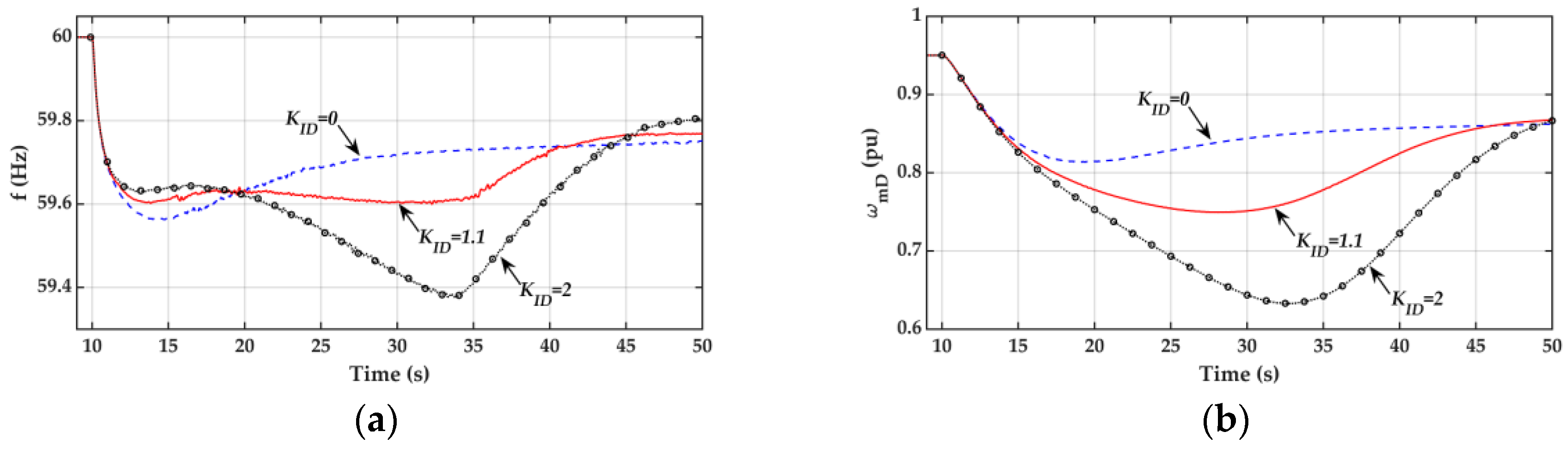
  • The frequency response curves for the three cases are essentially the same during the inertia period (1–2 s after the disturbance or 10 s ≤ t ≤ 11–12 s) since the frequency nadir is of major concern and inertia control is not considered in this work.
  • The frequency nadir for Case 1 with only a droop controller is lower than the prespecified threshold of 59.6 Hz.
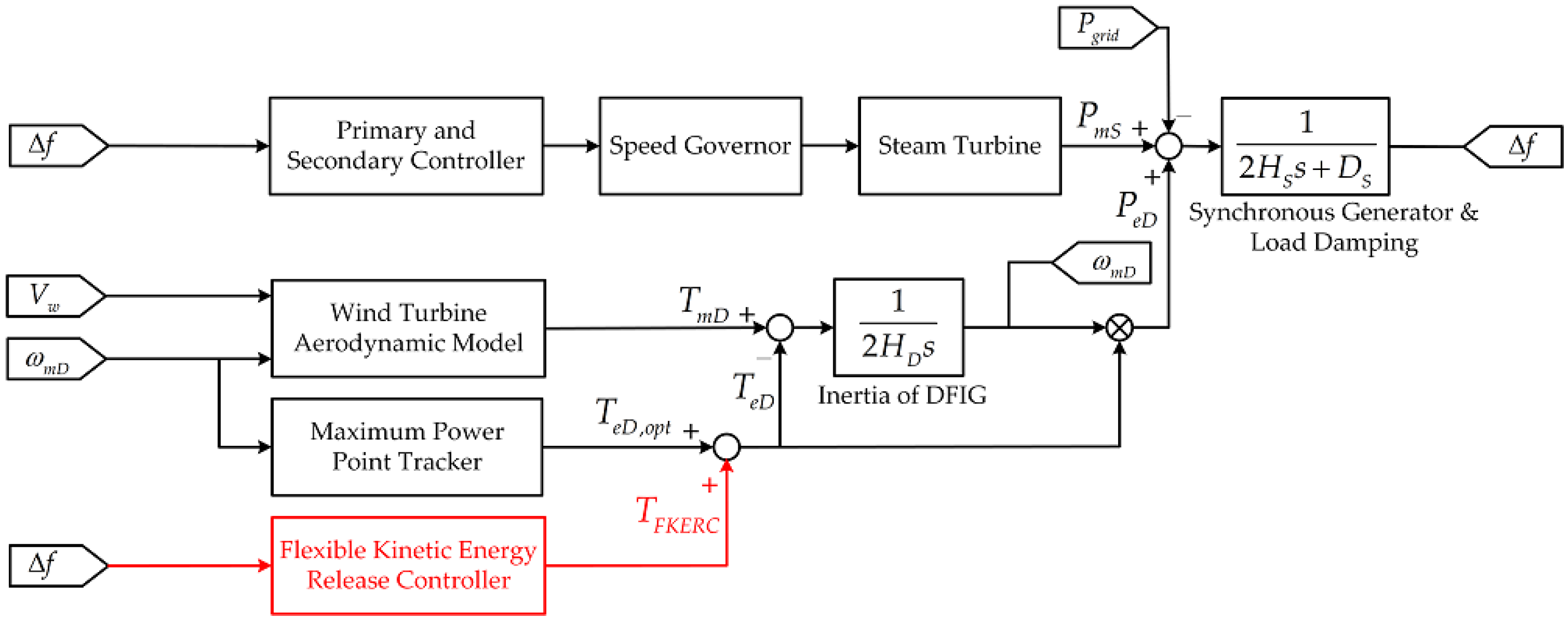
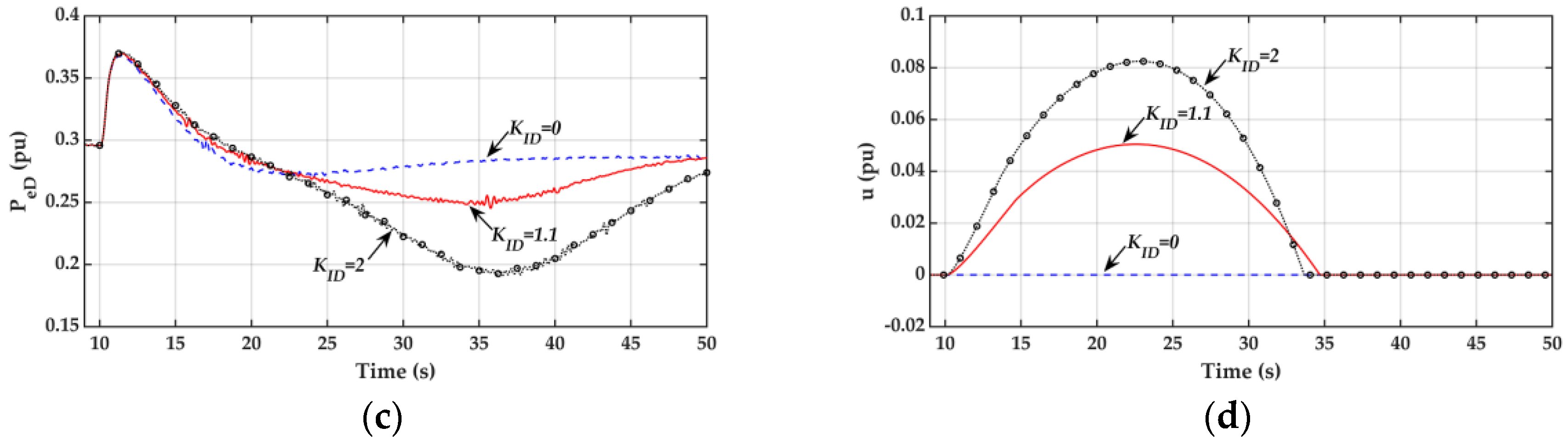
  • With the proposed Type I flexible kinetic energy release controller, the frequency nadir is improved to a value higher than the threshold of 59.6 Hz. This is achieved through the addition of an integral controller with a gain of KID = 1.1. As shown in Figure 9c,d, both the DFIG electrical power PeD and control signal are increased by the proposed Type I flexible kinetic energy release controller during the first few seconds in the primary frequency regulation period (12 s ≤ t ≤ 22 s)
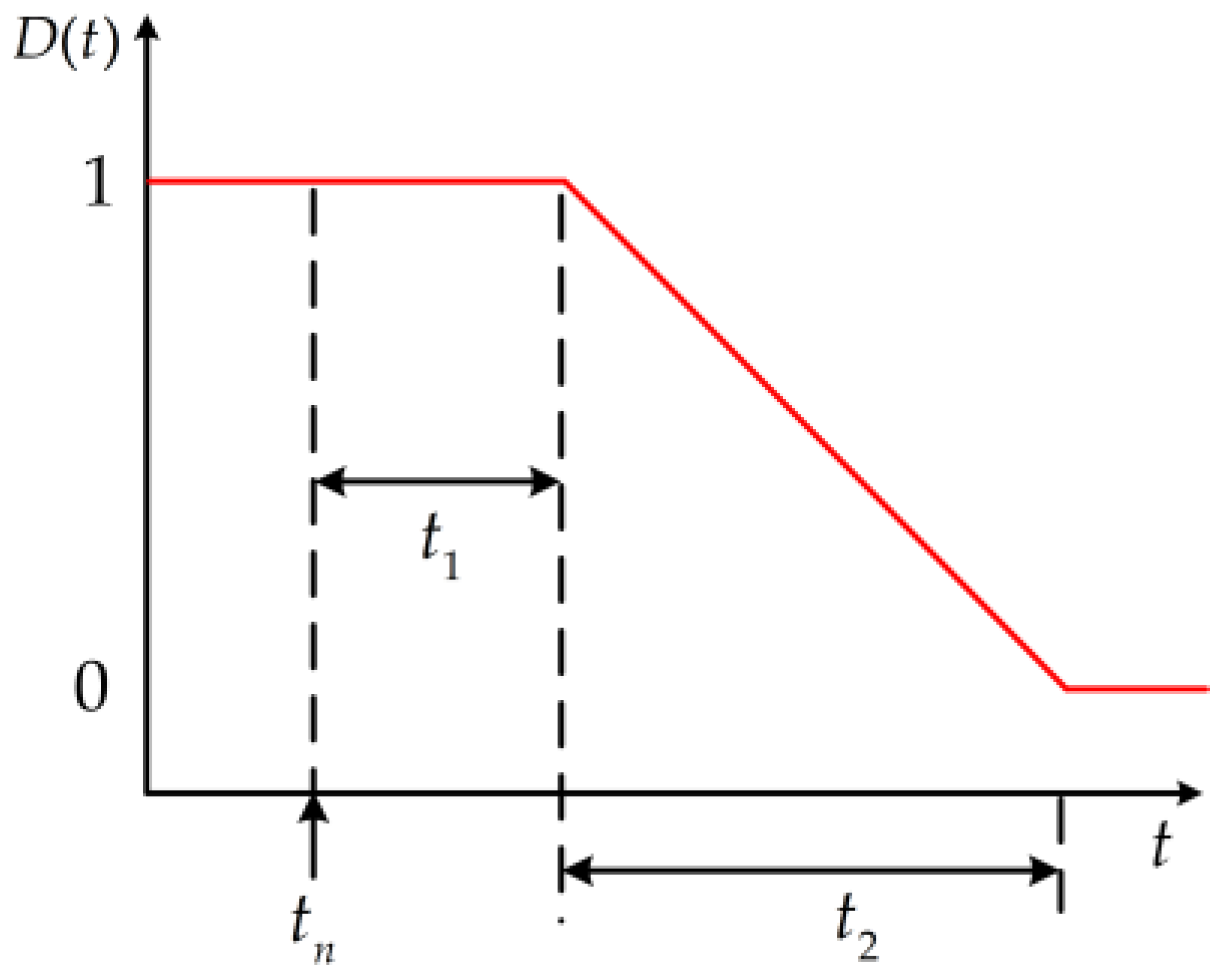
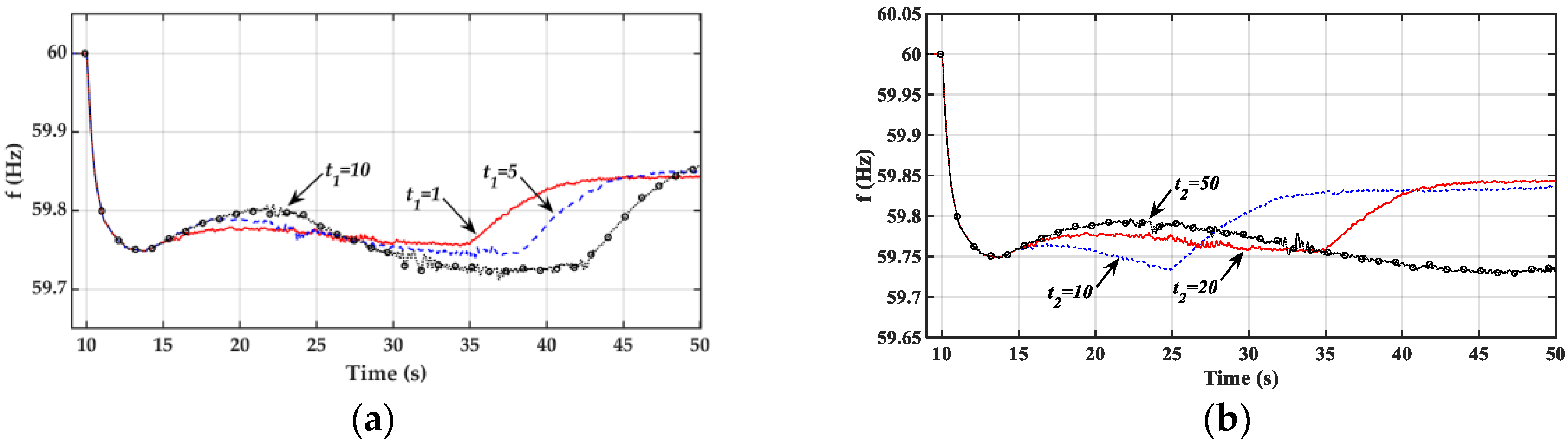
  • As evidenced by the response curve in Figure 9d, the control signal u from the proposed Type I flexible kinetic energy release controller is gradually increased when the system frequency drops to 59.9 Hz at t = 10.5 s. The deactivation function in Figure 4 begins to work at t = 13 s when the frequency nadir is detected. Due to the action of deactivation function, the rate of change of control signal u is gradually decreased and the control signal u is decreased to zero in a very smooth manner in order to avoid the second frequency nadir.
  • Although the DFIG output power PeD can be further increased and the first frequency nadir at around t = 13 s can be improved further using a higher integral gain of KID = 2 for the Type I flexible kinetic energy release controller, the DFIG speed will drop significantly and the DFIG kinetic energy will be exhausted in the primary frequency regulation period. As a result, a very low second frequency nadir (59.4 Hz) will be observed at t = 34 s. A moderate gain of KID = 1.1 seems to be a good choice for the study system.

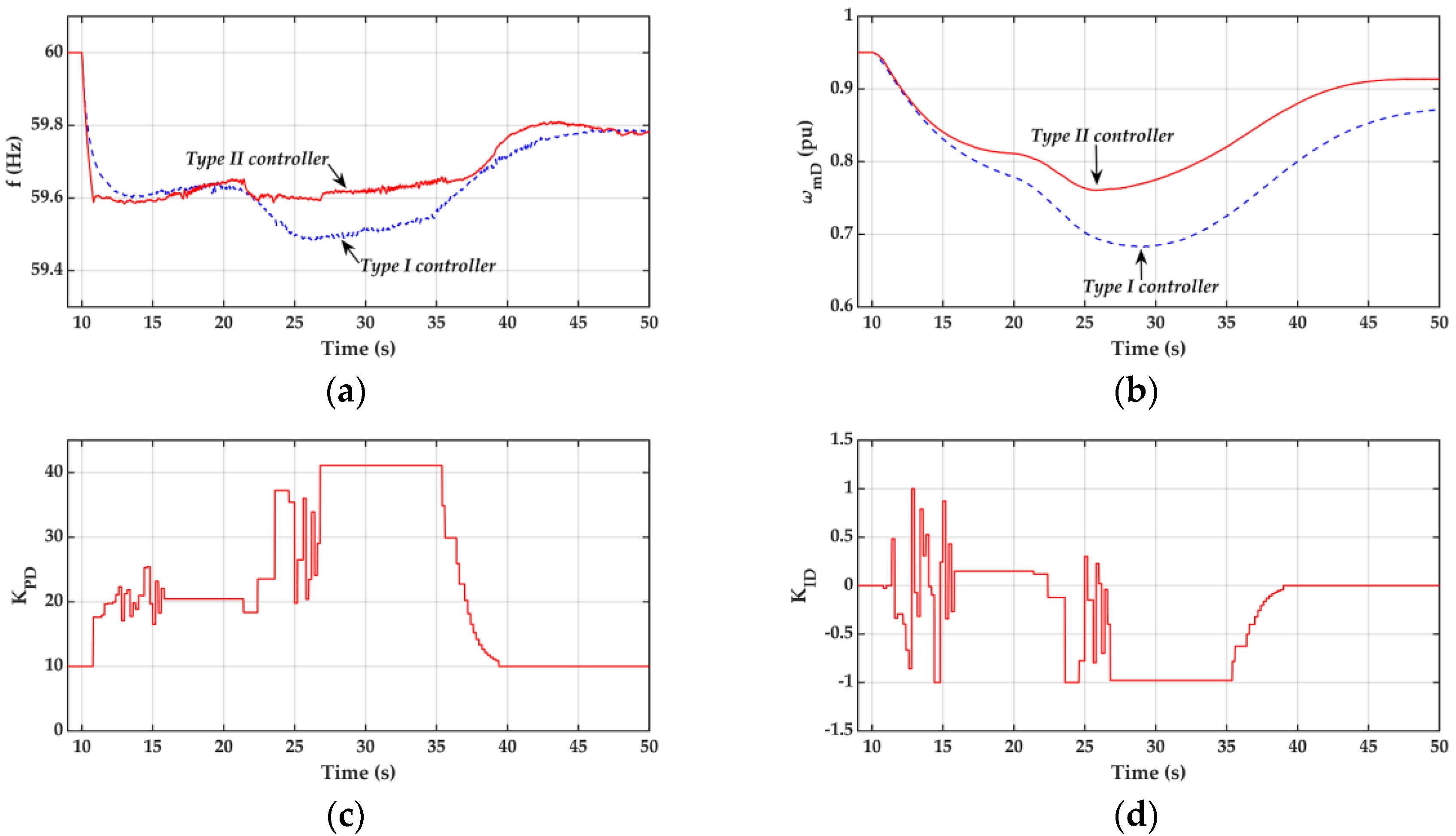
5.2. Dynamic Performance of Type II Flexible Kinetic Energy Release Controller

Detailed comparisons of the dynamic frequency responses for the system with Type I and Type II flexible kinetic energy release controllers, when the system is subject to parameter uncertainties and external disturbances, are described below.

5.2.1. Dynamic Response Curves under Uncertainties in System Parameters Servo-Motor Time Constant Tsm and Reheater Time Constant Tt4 (Pgrid = 45 MW, Vw = 11 m/s, Tsm = 0.375 s, Tt4 = 6.625 s)

To investigate the dynamic performance of the Type II controller under parameter uncertainties, the servo-motor time constant T sm and the reheater time constant T t 4 , were changed from 0.3 and 5.3 s to 0.375 and 6.625 s, respectively. It is assumed that the Type II controller is unaware of the change in system parameters. The dynamic response curves from the Type I and Type II controllers are compared in Figure 10. Note that the initial gains for the Type II controller were set to be K PD = 10 and K ID = 0.
It is observed from the frequency response curves in Figure 10a, for the case of T sm = 0.375 s and T t 4 = 6.625 s, that the system frequency nadir is lower than the threshold of 59.6 Hz when a Type I controller with the same controller gains of K PD = 20, K ID = 1.1, and deficit power P grid = 45 MW as those used in Figure 9 was employed. Recall that the Type I controller with the gains K PD = 20 and K ID = 1.1 gave a satisfactory frequency response for the system with the original parameters ( T sm = 0.3 s and T t 4 = 5.3 s), as shown in Figure 9a. Therefore, it is concluded that the frequency response from a Type I controller is sensitive to system parameter variations.
On the other hand, as evidenced by the response curve in Figure 10a, the frequency nadir remained around 59.6 Hz when the Type II controller was employed. As shown in Figure 10c,d, an improvement of the system frequency response was achieved by the Type II controller through the use of a pair of lower initial gains ( K PD = 10, K ID = 0) immediately following the grid disconnection. As explained earlier, more kinetic energy retained in the DFIG as a result of lower initial gains during the first few seconds after disturbance enabled the DFIG to deliver more electrical power to the islanding system and to improve frequency response.
As shown in Figure 10c,d, the Type II controller was started when the frequency was lower than 59.6 Hz and higher gains for K PD and K ID from the Type II controller forced the DFIG to deliver more electrical power to the system. With the increase of the electrical power output from the DFIG, the system frequency was improved. In order to return to the MPPT operation mode, when the system frequency exceeded 59.65 Hz, the PSO gains were gradually decayed to the initial values ( K PD = 10, K ID = 0).

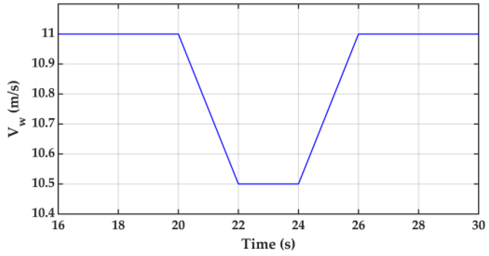
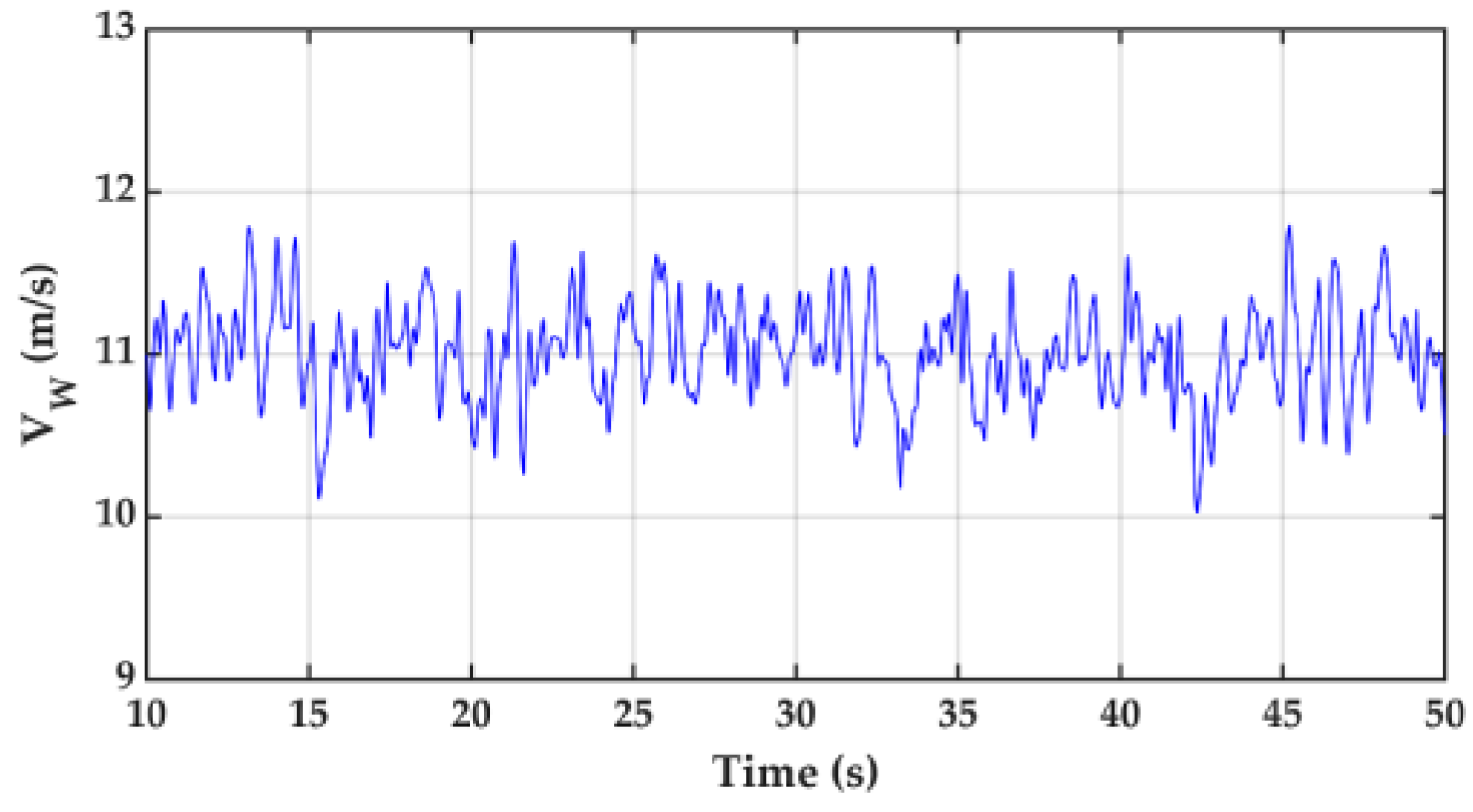
5.2.2. Dynamic Response Curves under Change of Wind Speed

To examine the dynamic performance of the Type II controller under a change of wind speed as shown in Figure 11, Figure 12 depict the dynamic response curves for this case.
Since the gains of the Type I controller had been selected based on a fixed wind speed of V w = 11 m/s, the system frequency nadir failed to meet the requirement of 59.6Hz when the system was subject to a wind speed change, as evidenced by the frequency response curve in Figure 12a. However, the Type II controller can still maintain a satisfactory frequency response by adjusting the controller gains in real-time when the system is subject to a wind speed change, as shown in Figure 12c,d.

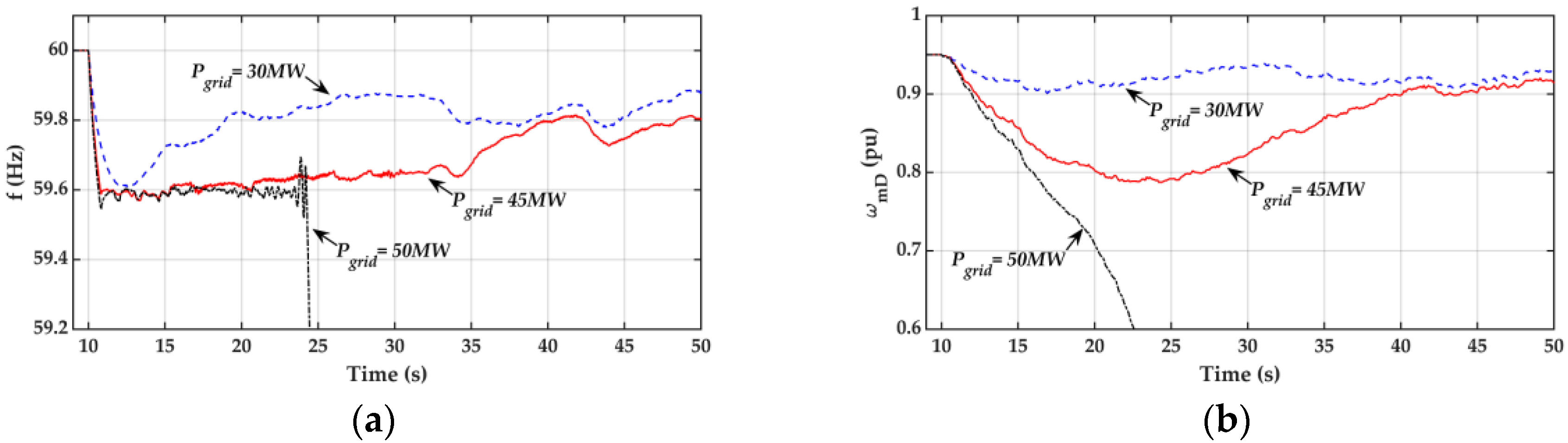
5.2.3. Dynamic Response Curves under Uncertainties in System Parameters and Fluctuation of Wind Speed in Different Pgrid

In order to assess the effectiveness of the Type II controller, the dynamic responses for different values of P grid under the combined effects of the SG time constant change, as described in Section 5.2.1, and the wind speed fluctuation, as shown in Figure 13, are depicted in Figure 14.
Based on the dynamic response curves in Figure 14, the following observations can be made.
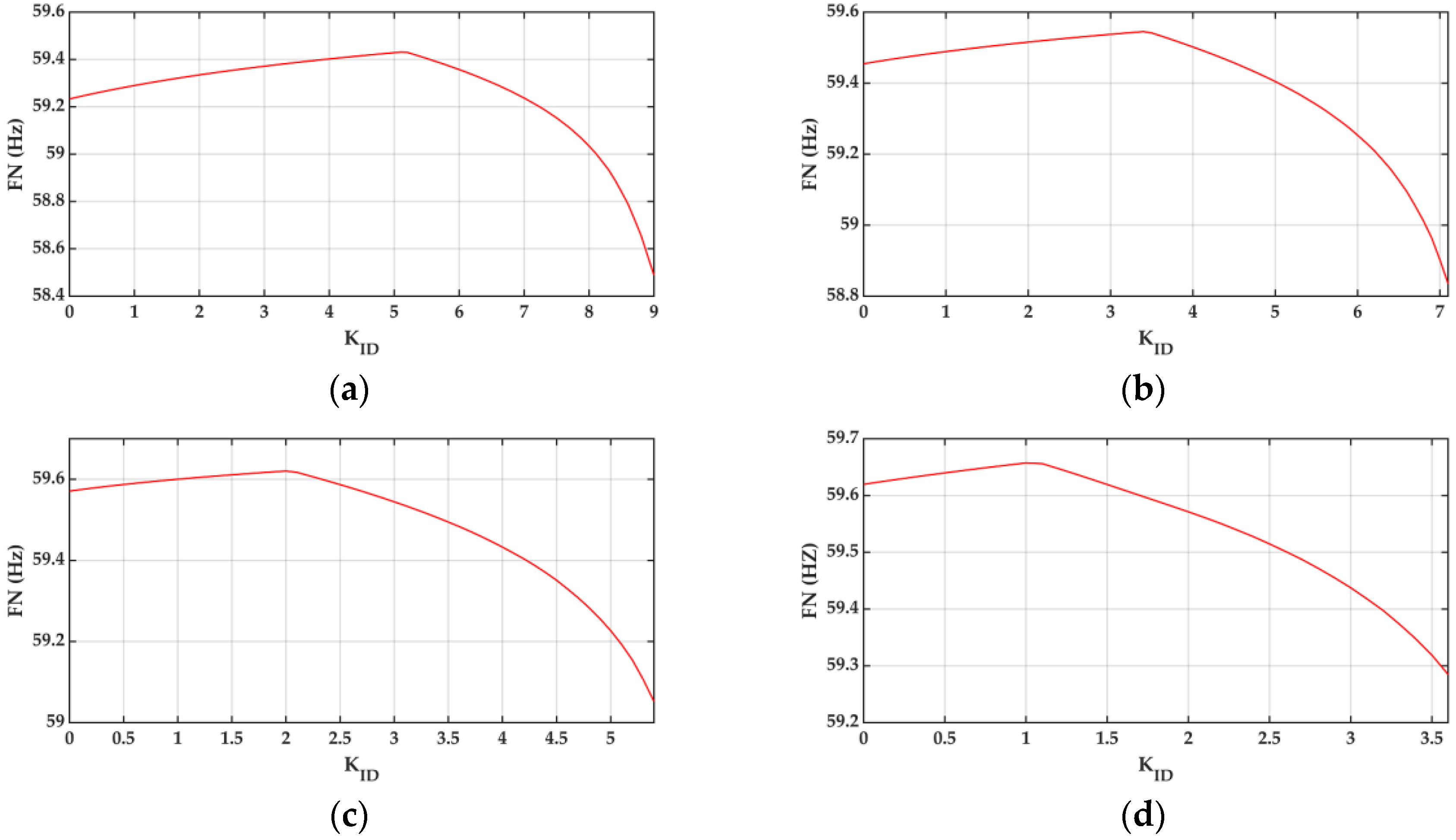
  • When the deficit power Pgrid is 30 MW, the PSO algorithm will not be initiated since the frequency response during the entire post-fault period is higher than the threshold of 59.6 Hz. Therefore, the controller gains for the Type II controller will remain at the initial values (KPD = 10, KID = 0).
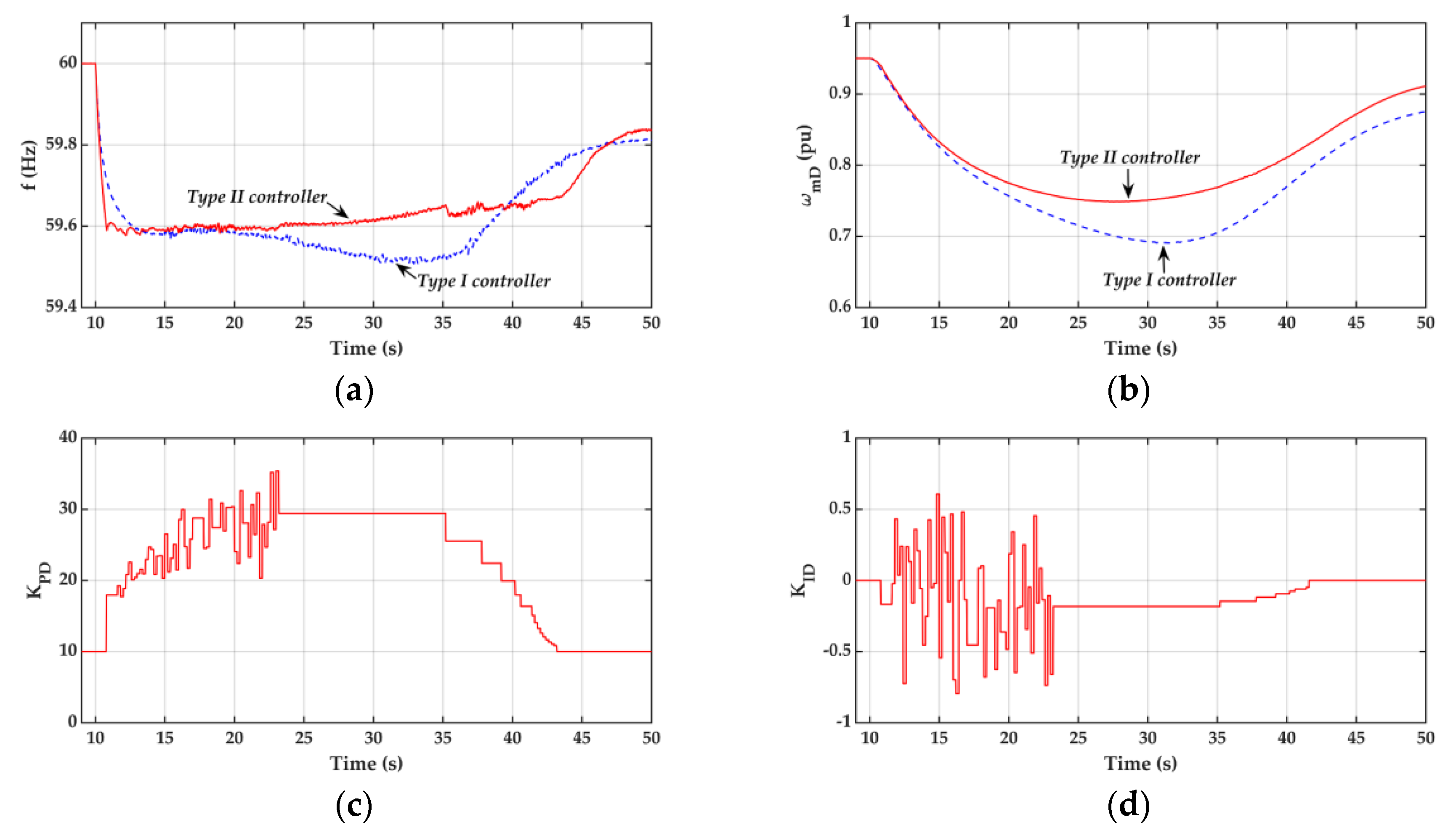
  • As the deficit power Pgrid is increased to 45 MW, the controller gains for the Type II controller can be adjusted online to improve the frequency response, even though the PSO algorithm is unaware of the change in SG parameters and the fluctuations in wind speed.
  • When the system encounters a large deficit power, e.g., Pgrid= 50 MW, the system frequency can be kept around 59.6 Hz in the first few seconds after disturbance using the proposed Type II controller. However, the DFIG stall and frequency collapse are observed afterwards since the large deficit power exceeds the upper limit of the DFIG stored kinetic energy, which can be released to the power system under disturbance conditions.

6. Conclusions

Two flexible kinetic energy release controllers have been designed for a DFIG to improve the frequency nadir of an islanding system, comprising an equivalent SG and an equivalent DFIG. Specific conclusions are summarized as follows:
  • The Type II flexible kinetic energy release controller with the controller gains being adapted in real-time, using the PSO technique, has been found to be able to offer a better dynamic frequency response than the Type I controller when the system is subject to external disturbances or parameter variations.
  • In this paper, the pitch angle is set to be zero to avoid considerable revenue losses. However, the de-loaded operation may be used to improve the system frequency at the price of revenue loss when the deficit power exceeds the DFIG kinetic energy limit.
  • Although the dynamic frequency response can be improved by the proposed Type I and Type II controllers, the delay time and decay time in the Type I controller must be properly designed in order to achieve good performance. In addition, it takes a long time for the PSO algorithm to reach the desired optimal gains of KPD and KID. In order to reduce the computational burden, it is necessary to limit the number of particles per iteration. However, the local minimum may be experienced as a result of an insufficient number of particles.
  • Future work will be devoted to the implementation and field test of the proposed controllers. Furthermore, the coordination between the pitch angle controller and the proposed controller will be investigated.

Author Contributions

Conceptualization, methodology, validation, and investigation, Y.-W.C.; writing—original draft, supervision, and project administration, Y.-Y.H. Both authors have read and agreed to the published version of the manuscript.

Funding

This research was funded by the Ministry of Science and Technology of Taiwan, grant number MOST 106-2221-E-002-147-MY3 and the APC was funded by the Ministry of Science and Technology of Taiwan.

Acknowledgments

This work was supported by the Ministry of Science and Technology of Taiwan, under contract MOST 106-2221-E-002-147-MY3. Cheng-Hung Chuang and Tien-Kuei Lu provided valuable system data and comments.

Conflicts of Interest

The authors declare that they have no known competing financial interests or personal relationships, which could have appeared to influence the work reported in this paper.

Nomenclature

D S load damping
D (t)deactivation function
H S ,   H D equivalent inertia time constants of synchronous machine and DFIG
f system frequency
K PD ,   K ID DFIG supplementary proportional and integral controller gain
P grid grid power
P eD electromagnetic power of DFIG
P mS mechanical power of synchronous machine
T mD ,   T eD mechanical torque and electromagnetic torque of DFIG
T eD , opt electromagnetic torque command of DFIG for MPPT
T FKERC flexible kinetic energy release control signal
t 1 , t 2 , t n decay time, delay time, and nadir frequency time
ω mD DFIG speed
V W wind speed
incremental quantity

Appendix A

Speed governor and turbine:
Droop and integral controller gains:   K PS = 20 and K IS = 0.1.
Speed relay and servo-motor time constants: T sr = 0.1 s and T sm = 0.3 s.
Steam chest, reheater, and crossover time constants: T t 5 = 0.68 s, T t 4 = 5.3 s, and T t 3 = 0.58 s.
Power fractions: F 5 = 0.241, F 4 = 0.399, and F 3 = 0.360.
Synchronous machine:
Rated power: 480 MVA.
Rated voltage: 18 kV.
Rated frequency: 60 Hz.
Number of poles: 2 poles.
Machine parameters: H S = 3.3 s, D S = 0.
DFIG:
Rated power: 200 MVA.
Rated voltage: 690 V.
Proportional and integral gains of q-axis rotor current regulator: K pq = 0.0756, K iq = 0.8318.
Stator, rotor, and mutual inductances: L s = 3.1 pu, L r = 3.08 pu, and L m = 3 pu.
Rotor resistance: R r = 0.01 pu.
Number of poles: 4 poles.
Machine parameters: H D = 3.5 s.
Loads:
Load 1 = 26 MW; Load 2 = 160 MW; Load 3 = 50 MW; Load 4 = 24 MW.
Infinite bus parameters:
Rated short-circuit power: 11,072.92 MVA.
Rated short-circuit current: 39.71 kA.
Rated voltage: 161 kV.
X/R ratio: 31.6912.

References

  1. Shahabi, M.; Haghifam, M.R.; Mohamadian, M.; Nabavi-Niaki, S.A. Microgrid dynamic performance improvement using a doubly fed induction wind generator. IEEE Trans. Energy Convers. 2009, 24, 137–145. [Google Scholar] [CrossRef]
  2. Mauricio, J.M.; Marano, A.; Gomez-Exposito, A.; Ramos, J.L.M. Frequency regulation contribution through variable-speed wind energy conversion systems. IEEE Trans. Power Syst. 2009, 24, 173–180. [Google Scholar]
  3. Arani, M.F.M.; Mohamed, Y.A.I. Analysis and impacts of implementing droop control in DFIG-based wind turbines on microgrid/weak-grid stability. IEEE Trans. Power Syst. 2015, 30, 385–396. [Google Scholar]
  4. Hwang, M.; Muljadi, E.; Park, J.; Sørensen, P.; Kang, Y.C. Dynamic droop–based inertial control of a doubly-fed induction generator. IEEE Trans. Sustain. Energy 2016, 7, 924–933. [Google Scholar]
  5. Lee, J.; Jang, G.; Muljadi, E.; Blaabjerg, F.; Chen, Z.; Kang, Y.C. Stable short-term frequency support using adaptive gains for a DFIG-based wind power plant. IEEE Trans. Energy Convers. 2016, 31, 1068–1079. [Google Scholar]
  6. Arani, M.F.M.; Mohamed, Y.A.I. Dynamic droop control for wind turbines participating in primary frequency regulation in microgrids. IEEE Trans. Smart Grid 2018, 9, 5742–5751. [Google Scholar]
  7. Garmroodi, M.; Verbič, G.; Hill, D.J. Frequency support from wind turbine generators with a time-variable droop characteristic. IEEE Trans. Sustain. Energy 2018, 9, 676–684. [Google Scholar] [CrossRef]
  8. Yang, J.; Chen, Y.; Hsu, Y. Small-signal stability analysis and particle swarm optimisation self-tuning frequency control for an islanding system with DFIG wind farm. IET Gener. Transm. Distrib. 2019, 13, 563–574. [Google Scholar]
  9. Li, Y.; Xu, Z.; Zhang, J.; Wong, K.P. Variable gain control scheme of DFIG-based wind farm for over-frequency support. Renew. Energy 2018, 120, 379–391. [Google Scholar] [CrossRef]
  10. Hwang, M.; Muljadi, E.; Jang, G.; Kang, Y.C. Disturbance-adaptive short-term frequency support of a DFIG associated with the variable gain based on the ROCOF and rotor speed. IEEE Trans. Power Syst. 2017, 32, 1873–1881. [Google Scholar] [CrossRef]
  11. Hafiz, F.; Abdennour, A. An adaptive neuro-fuzzy inertia controller for variable-speed wind turbines. Renew. Energy 2016, 92, 136–146. [Google Scholar] [CrossRef]
  12. Qudaih, Y.S.; Bernard, M.; Mitani, Y.; Mohamed, T.H. Model predictive based load frequency control design in the presence of DFIG wind turbine. In Proceedings of the 2011 2nd International Conference on Electric Power and Energy Conversion Systems (EPECS), Sharjah, UAE, 15–17 November 2011; pp. 1–5. [Google Scholar]
  13. Mohamed, T.H.; Morel, J.; Bevrani, H.; Hiyama, T. Model predictive based load frequency control_design concerning wind turbines. Int. J. Electr. Power Energy Syst. 2012, 43, 859–867. [Google Scholar] [CrossRef]
  14. Tielens, P.; Hertem, D.V. Receding horizon control of wind power to provide frequency regulation. IEEE Trans. Power Syst. 2017, 32, 2663–2672. [Google Scholar] [CrossRef]
  15. Wang, H.; Yang, J.; Chen, Z.; Ge, W.; Ma, Y.; Xing, Z.; Yang, L. Model predictive control of PMSG-based wind turbines for frequency regulation in an isolated grid. IEEE Trans. Ind. Appl. 2018, 54, 3077–3089. [Google Scholar] [CrossRef]
  16. Zhang, S.; Mishra, Y.; Shahidehpour, M. Fuzzy-logic based frequency controller for wind farms augmented with energy storage systems. IEEE Trans. Power Syst. 2016, 31, 1595–1603. [Google Scholar] [CrossRef]
  17. Ghafouri, A.; Milimonfared, J.; Gharehpetian, G.B. Fuzzy-adaptive frequency control of power system including microgrids, wind farms, and conventional power plants. IEEE Syst. J. 2018, 12, 2772–2781. [Google Scholar] [CrossRef]
  18. Abazari, A.; Monsef, H.; Wu, B. Load frequency control by de-loaded wind farm using the optimal fuzzy-based PID droop controller. IET Renew. Power Gener. 2019, 13, 180–190. [Google Scholar] [CrossRef]
  19. Wu, Y.; Yang, W.; Hu, Y.; Dzung, P.Q. Frequency regulation at a wind farm using time-varying inertia and droop controls. IEEE Trans. Ind. Appl. 2019, 55, 213–224. [Google Scholar] [CrossRef]
  20. Geng, H.; Xi, X.; Yang, G. Small-signal stability of power system integrated with ancillary-controlled large-scale DFIG-based wind farm. IET Renew. Power Gener. 2017, 11, 1191–1198. [Google Scholar] [CrossRef]
  21. Lee, J.; Muljadi, E.; Srensen, P.; Kang, Y.C. Releasable kinetic energy-based inertial control of a DFIG wind power plant. IEEE Trans. Sustain. Energy 2016, 7, 279–288. [Google Scholar] [CrossRef]
  22. Vyver, J.V.d.; Kooning, J.D.M.D.; Meersman, B.; Vandevelde, L.; Vandoorn, T.L. Droop control as an alternative inertial response strategy for the synthetic inertia on wind turbines. IEEE Trans. Power Syst. 2016, 31, 1129–1138. [Google Scholar] [CrossRef]
  23. Vidyanandan, K.V.; Senroy, N. Primary frequency regulation by deloaded wind turbines using variable droop. IEEE Trans. Power Syst. 2013, 28, 837–846. [Google Scholar] [CrossRef]
  24. Kayikci, M.; Milanovic, J.V. Dynamic contribution of DFIG-based wind plants to system frequency disturbances. IEEE Trans. Power Syst. 2009, 24, 859–867. [Google Scholar]
  25. Ramtharan, G.; Ekanayake, J.B.; Jenkins, N. Frequency support from doubly fed induction generator wind turbines. IET Renew. Power Gener. 2007, 1, 3–9. [Google Scholar]
  26. Morren, J.; Pierik, J.; De Haan, S.W.H. Inertial response of variable speed wind turbines. Electr. Power Syst. Res. 2006, 76, 980–987. [Google Scholar] [CrossRef]
  27. Morren, J.; Haan, S.W.H.d.; Kling, W.L.; Ferreira, J.A. Wind turbines emulating inertia and supporting primary frequency control. IEEE Trans. Power Syst. 2006, 21, 433–434. [Google Scholar] [CrossRef]
  28. Zhang, X.; Zhu, Z.; Fu, Y.; Li, L. Optimized virtual inertia of wind turbine for rotor angle stability in interconnected power systems. Electr. Power Syst. Res. 2020, 180, 106157. [Google Scholar] [CrossRef]
  29. Kundur, P. Power System Stability and Control; McGraw-Hill Education: New York, NY, USA, 1994. [Google Scholar]
  30. Eberhart, R.; Kennedy, J. A new optimizer using particle swarm theory. In MHS’95. Proceedings of the Sixth International Symposium on Micro Machine and Human Science, Nagoya, Japan, 4–6 October 1995; IEEE: New York, NY, USA; pp. 39–43.
  31. Kennedy, J.; Eberhart, R. Particle swarm optimization. In Proceedings of the ICNN’95—International Conference on Neural Networks, Perth, WA, Australia, 27 November–1 December 1995; Volume 1944, pp. 1942–1948. [Google Scholar]
Figure 1. One-line diagram for the studied local power system.
Energies 13 06135 g001
Figure 2. Frequency control functional block diagram for the islanding system.
Energies 13 06135 g002
Figure 3. Deactivation function based integral controller.
Energies 13 06135 g003
Figure 4. Deactivation function for the integral controller.
Energies 13 06135 g004
Figure 5. Effects of different delay times (t1) and decay times (t2) on system frequency. (a) Different delay, Table 1. (b) Different decay times (t2).
Energies 13 06135 g005
Figure 6. Effect of integral controller gain KID on frequency nadir under different values of KPD (a) KPD = 5, (b) KPD = 10, (c) KPD = 15, (d) KPD = 20.
Energies 13 06135 g006
Figure 7. Particle swarm optimization (PSO) based adaptive Proportional-Integral (PI) controller.
Energies 13 06135 g007
Figure 8. Schematic diagram of particle positions and velocities in every iteration.
Energies 13 06135 g008
Figure 9. Comparison of dynamic response curves from different integral gains (KPD = 20, Pgrid = 45 MW, Vw = 11 m/s). (a) Frequency, (b) DFIG speed, (c) DFIG electrical power, (d) deactivation function based integral control signal.
Energies 13 06135 g009aEnergies 13 06135 g009b
Figure 10. Comparison of dynamic response curves from the Type I and Type II controllers under change of system parameters T s m and T t 4 ( P g r i d = 45 MW, V w = 11 m/s, T s m = 0.375 s, T t 4 = 6.625 s). (a) Frequency, (b) DFIG speed, (c) PSO proportional gain, (d) PSO integral gain.
Energies 13 06135 g010
Figure 11. Variation of wind speed.
Energies 13 06135 g011
Figure 12. Comparison of dynamic response curves from the Type I and Type II controllers under change of wind speed ( P g r i d = 45 MW). (a) Frequency, (b) DFIG speed, (c) PSO proportional gain, (d) PSO integral gain.
Energies 13 06135 g012
Figure 13. Fluctuation of wind speed.
Energies 13 06135 g013
Figure 14. Dynamic response curves of the Type II controller under parameters uncertainties and the fluctuation of wind speed at different deficit powers. (a) Frequency, (b) DFIG speed.
Energies 13 06135 g014
Table 1. Summary of supplementary frequency controllers for doubly fed induction generator (DFIG).
Controller/AlgorithmOperating Conditions DependentNeeds TrainingNeeds Rule BaseNeeds Evaluation FunctionComputational Burden
PID [1,2,3,4,5,6,7,8,9,10,19,20,21,22,23,24,25,26,27,28]YESNONONOLOW
ANN [11]NOYESNONOLOW
MPC [12,13,14,15]NONONOYESHIGH
Fuzzy [16,17,18]NONOYESNOLOW
Type IYESNONONOLOW
Type IINONONOYESHIGH
Table 2. The highest frequency nadir for various combinations of KPD and KID under different values of Pgrid.
KPDKIDFN
Pgrid = 30 MW55.559.63
103.759.70
152.359.75
201.359.78
Pgrid = 35 MW55.459.56
103.659.65
152.259.71
201.259.74
Pgrid = 40 MW55.359.50
103.559.60
152.159.67
201.159.70
Pgrid = 45 MW55.159.43
103.459.55
15259.62
20159.66
Publisher’s Note: MDPI stays neutral with regard to jurisdictional claims in published maps and institutional affiliations.

