Article

Design and Operational Control Strategy for Optimum Off-Design Performance of an ORC Plant for Low-Grade Waste Heat Recovery

1
University of L’Aquila, Piazzale Ernesto Pontieri, Monteluco di Roio, 67100 L’Aquila, Italy
2
Clean Energy Processes (CEP) Laboratory, Department of Chemical Engineering, Imperial College London, South Kensington Campus, London SW7 2AZ, UK
3
Institute of Turbomachinery, Xi’an Jiaotong University, Xi’an 710049, China
*
Author to whom correspondence should be addressed.
Energies 2020, 13(21), 5846; https://doi.org/10.3390/en13215846
Submission received: 13 October 2020 / Revised: 30 October 2020 / Accepted: 3 November 2020 / Published: 9 November 2020
(This article belongs to the Special Issue Waste Energy Recovery and Valorization in Internal Combustion Engines)

Abstract

:
The applicability of organic Rankine cycle (ORC) technology to waste heat recovery (WHR) is currently experiencing growing interest and accelerated technological development. The utilization of low-to-medium grade thermal energy sources, especially in the presence of heat source intermittency in applications where the thermal source is characterized by highly variable thermodynamic conditions, requires a control strategy for off-design operation to achieve optimal ORC power-unit performance. This paper presents a validated comprehensive model for off-design analysis of an ORC power-unit, with R236fa as the working fluid, a gear pump, and a 1.5 kW sliding vane rotary expander (SVRE) for WHR from the exhaust gases of a light-duty internal combustion engine. Model validation is performed using data from an extensive experimental campaign on both the rotary equipment (pump, expander) and the remainder components of the plant, namely the heat recovery vapor generator (HRVH), condenser, reservoirs, and piping. Based on the validated computational platform, the benefits on the ORC plant net power output and efficiency of either a variable permeability expander or of sliding vane rotary pump optimization are assessed. The novelty introduced by this optimization strategy is that the evaluations are conducted by a numerical model, which reproduces the real features of the ORC plant. This approach ensures an analysis of the whole system both from a plant and cycle point of view, catching some real aspects that are otherwise undetectable. These optimization strategies are considered as a baseline ORC plant that suffers low expander efficiency (30%) and a large parasitic pumping power, with a backwork ratio (BWR) of up to 60%. It is found that the benefits on the expander power arising from a lower permeability combined with a lower energy demand by the pump (20% of BWR) for circulation of the working fluid allows a better recovery performance for the ORC plant with respect to the baseline case. Adopting the optimization strategies, the average efficiency and maximum generated power increase from 1.5% to 3.5% and from 400 to 1100 W, respectively. These performances are in accordance with the plant efficiencies found in the experimental works in the literature, which vary between 1.6% and 6.5% for similar applications. Nonetheless, there is still room for improvement regarding a proper design of rotary machines, which can be redesigned considering the indications resulting from the developed optimization analysis.

1. Introduction

The rising interest in small-scale organic Rankine cycle (ORC) plants for waste heat recovery (WHR) purposes, in applications characterized by time variable conditions associated with both the heat source and heat sink, raises the issue of off-design plant operation [1,2,3]. Whereas extensive literature deals with proving ORC thermodynamic feasibility in various WHR scenarios [4,5,6,7], the optimum plant design is relatively unexplored, based on the analysis of the plant hydraulics [8,9], i.e., the performance sensitivity to the (i) actual fluid charge in the plant [10]; (ii) revolution speed of the pump and expander [11,12]; (iii) lower and upper cycle pressures [13]; and (iv) heat exchangers behavior at part load conditions [14].
In general, ORC plant modeling considers user-imposed variables for the operating parameters, such as temperatures—superheating degree [15], subcooling degree [12,13,14,15,16], approach point temperatures [13]—and pressures, or a combination of temperatures and pressures [14], resulting in predictions that can deviate from real plant operation, which can vary significantly within a given envelope. Moreover, the possibility of actually implementing conditions close to such assumptions usually requires an increased plant complexity: a dedicated control strategy for pressure optimization [13], as well as the need to rely on rotary proper equipment if dynamic machines [14,15,16] or heat exchangers [17,18] highly customized for the specific application are used, rather than on-the-shelf technology. However, this means higher costs, reduced fail-safe, and not necessarily an extended range of the optimum operation of the plant. On the other hand, for small-scale power plants, the choice of rotary (scroll, sliding vane, screw) and linear (piston) volumetric expanders instead of dynamic machines ensures better facing the unsteady operating conditions, making the whole plant more reliable and robust [19,20]. Moreover, positive-displacement machines can operate at low operational speed, hence ensuring a less complex and expensive solution than that involving the scaling down of turbomachines [21]. As discussed extensively in Ref. [9] in the context of controlling ORC plant operation, the revolution speed of the rotary equipment is a same-rank variable as the working fluid properties or the characteristics of the heat source and sink. This is particularly critical in the case of both the pump and the expander when these are volumetric machines. With reference to the pump, the revolution speed directly controls the processed mass flow rate of the working fluid for each specific condition at the heat sink. At the expander, the revolution speed determines the expander permeability and the intake pressure.
As a matter of fact, a significant breakthrough in ORC plant design and optimization should be sought in a less constrained off-design analysis, with a deeper investigation of the effects of the system’s inertia in transient operation [22], optimum selection of the rotational speed for the expander and pump [11], and an optimum working fluid mass flow rate for each operating condition, which, in turn, reflects on the limited operating pressures of the plant. Another fundamental aspect is the working fluid selection, and to this aim, molecular-based models were developed to predict the thermodynamic properties of organic working fluids [23]. Moreover, the use of working fluid mixtures ensures enhancement of the thermodynamic performance relative to pure fluids [24,25,26].
In order to meet the expectations of such a novel approach, which aims to develop a detailed representation of the ORC plant integrating both plant and cycle analysis, the research mainly focused on the in-depth modeling of the heat exchangers for various cycle layouts to allow the calculation of the working fluid mass at both the design point and off-design conditions [27,28,29,30]. On the other hand, very little has been investigated, to date, on the plant hydraulic behavior and in particular on the plant permeability, which is defined as the attitude of the circuit to allow the fluid to pass through. This property was found to be fundamental in the relation between the mass flow rate circulating inside the plant and the maximum pressure [9]. The plant permeability is basically determined by the volumetric expander, which according to its volumetric efficiency sets the intake pressure for a given mass flow rate sent by the pump and when it is rotating at a certain speed [9]. Consequently, the dependence between the volumetric efficiency, leakages, and rotational speed is worth investigating, particularly in small-scale ORC units for WHR from unsteady thermal sources. It has been already observed [9,31,32] that real performance can be quite different from the idealized one evaluated by means of thermodynamic analysis without considering typical real plant features such as hydraulic permeability and the effect of expander leakages on the whole performance. From it, in fact, having fixed a specific cycle design for optimal operating conditions, the main relevant variables can be calculated in order to fulfill the desired goal: maximum efficiency, maximum thermal energy recovered, and maximum specific work, after which the optimum pressure or superheating degree can be easily determined. However, once the optimum pressure is calculated, it must be reached in a real plant, and this depends on a complex equilibrium between the permeability of the plant and the working fluid flow rate. The first parameter depends not only on many design variables (pipe diameter and length, circuit layout, presence of the reservoirs, dimension of the pump and expander, heat exchanger design, valve positions, etc.) but also on many operating conditions (revolution speed of the expander and of the pump, flow rate which calls for the enthalpy equilibrium at the heat recovery vapour generator (HRVG), valve operation, etc.) and some sub-design parameters (angular position of the inlet and exit ports of the expander, built-in volume ratio of the expander and on the pump, etc.). Indeed, all these parameters/variables determine the mass aspirated by the expander, setting the pressure of the working fluid at the expander intake and consequently the plant maximum pressure [9]. All these aspects should be managed in order to set up a desired maximum pressure on the plant equal to that determined by a thermodynamic analysis for a given mass flow rate circulating inside the plant.
In general, volumetric machines can achieve a higher rate of operational flexibility [33] in terms of high expansion ratios if piston expanders are used [34,35,36], as well as good reliability and good off-design performance in the case of sliding-vane machines being employed [31,37]. According to extensive literature on the drivers that define plant operating pressure [31,38,39], it can be assured that this parameter is fixed by the expander: the flow leakages associated with normal operation play a significant role in determining the optimal cycle parameters.
Particularly with sliding vane technology, a significant incidence of internal leakage on the machine energy and hydraulic performance must be expected, i.e., a loss of available work for a reduced mass flow rate, actually expanding and reduced volumetric efficiency [39]. As the flow leakage gets larger, the matching point between the hydraulic characteristics of the circuit and the pump shifts toward larger required mass flow rates to compensate for the pressure loss at the expander inlet. As a result, when the plant is conceived to operate with a constant upper pressure, an additional pump power consumption is expected with respect to design conditions and eventually a high backwork ratio (BWR) applies, which is the ratio between the work consumed by the pump and the work available at the expander shaft, and it could end up questioning the plant’s feasibility. In a complementary sliding pressure scenario, some variability on the expander inlet pressure is accepted: no additional pumping work is required, but the plant operates mostly under off-design conditions with obvious performance penalties. On the other hand, the discharge pressure is fixed by the condenser condition, thus defining the pressure ratio across the expander [40,41].
All these real plant features introduce complexities that should be taken into account in the off-design optimization and call for the setting up of a dedicated optimization strategy. In order to develop a predictive computational design tool for the optimum design of a small-scale ORC plant, a comprehensive model of the plant is developed in the present paper. The research work deals with the experimental validation of the comprehensive model based on data collected from an extensive experimental campaign performed on an ORC plant for WHR on the exhaust gases of a light-duty IVECO F1C 3-L supercharged diesel engine with R236fa as the working fluid. During the experimental and numerical analysis, the intrinsic variability of both plant operating parameters (e.g., working fluid mass flow rate) and driving conditions (e.g., internal combustion engine (ICE) speed and torque) were varied in order to induce a continuous off-design operation of the bottoming ORC plant.
Once validated, the model allows us to analyze the ORC plant, reproducing its real layout, taking into account in particular the real pipe distribution, the volume of the components, and the mass of the working fluid charge. Therefore, it allows performing a plant analysis via the prediction of the plant permeability and the definition of the condensation conditions according to the cooling medium state. Thanks to these peculiarities, the model is used to assess the validity of optimization strategies employed to improve plant performance within a wide range of operating conditions.

2. Materials and Methods

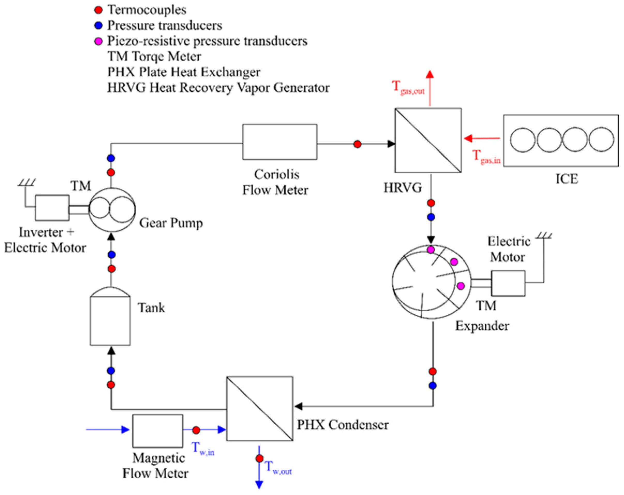
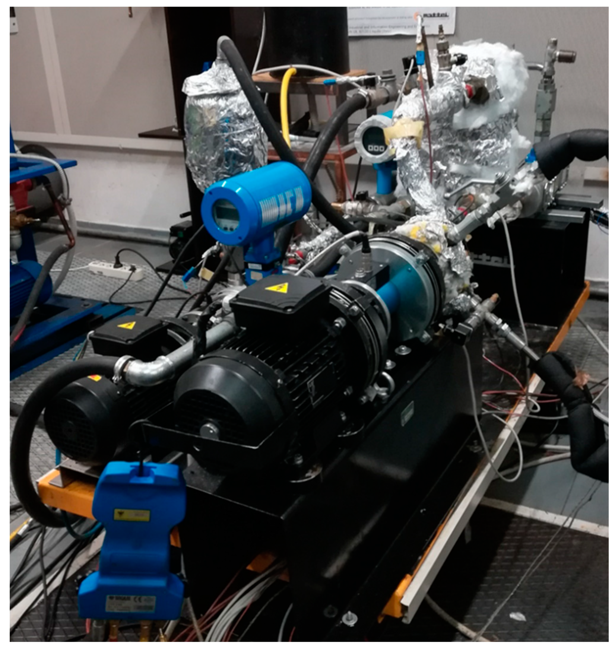
2.1. Experimental Layout

Figure 1 shows a schematic diagram of the ORC plant on which the experimental activity was performed. The ORC plant recovers thermal energy from the exhaust gases of a light-duty IVECO F1C 3-L diesel engine, and the experimental facility is located in the “Carmelo Caputo” Fluid Machine Laboratory at University of L’Aquila. Two important criteria arise when selecting the working fluid, which are the optimal utilization of the heat source and the achievement of high thermal efficiency and power density [42]. Nevertheless, additional criteria including environmental aspects such as flammability, toxicity, global warming potential (GWP), and ozone depletion potential (ODP) should be considered during working fluid selection [43]. In Ref. [43], it was stated that some fluids that present acceptable environmental indicators (near-zero ODP and GWP < 200) are flammable and can be employed only in such applications that meet the safety standard requirements. In addition, working fluid mixtures present an interesting opportunity, in particular for such applications with limited or constrained cooling resources; however, cycles with more volatile working fluid are more efficient and cost effective and ensure the recovery of a higher thermal power [23]. Another important aspect to take into account is the dynamic response of the ORC plant, which is affected also by the working fluid selection. In particular, ORC plants with working fluid suitable for low-temperature operation tend to respond faster than plants with fluids suitable for high-temperature operation [44].
In the current application, R236fa was selected as the working fluid, so that a direct comparison would be possible with the experimental results from previous studies by the authors [9,45]. Moreover, R236fa shows a lower cost and similar thermophysical properties to R245fa, which is one of the most suitable working fluids for waste heat recovery in internal combustion engines [46,47] despite other fluids such as ethanol and R236ea showing better thermodynamic performance [48], and it has been successfully employed in small-scale ORC systems [49].
For the heat recovery vapor generator (HRVG), the plate-and-fin technology was selected to reduce the backpressure-induced pressure losses that adversely affect both the engine performance and the heat transfer to the bottoming ORC plant. A gear pump driven by a variable speed electric motor allows achieving the upper cycle pressure, from which the working fluid expands in a 1.5 kW sliding vane rotary expander (SVRE). The expander has a radial intake port and an axial exhaust port, its stator, rotor diameter and chamber height are equal to 75.9 mm, 65 mm, and 60 mm, respectively. The machine has 7 chambers and 7 blades whose thickness and length are equal 17 mm and 4 mm, with a blade mass of 25 g. All these geometry features are reported in Table 1.
A constant 1500 RPM rotational speed is imposed by the connection to the electric grid, which is mediated by the asynchronous generator. A plate heat exchanger acts as the condenser, with water as the cooling medium. A receiver downstream of the condenser dumps flow rate fluctuations and prevents cavitation at the pump by keeping the pump intake pressure at a constant level. The receiver is a buffer vessel that can be also introduced between the evaporator and expander to suppress the variation in vapor quality at expander inlet, as it was done in [50]. The reconstruction of the indicated diagram by means of angularly spaced piezoresistive sensors along with the volumetric efficiency and shaft torque measurement allows a complete characterization of the expander performance.
In Figure 2, the experimental ORC plant is reported. The plant was developed to recover the exhaust gases of an IVECO F1C a 3-L supercharged diesel engine, as shown in Figure 3. From the analysis of Figure 2, it can be observed that as the gear pump (Figure 4a) pressurizes, the working fluid (R236fa) flows in the HRVG (Figure 4b) vaporizes, recovering thermal energy by the exhaust gases of the ICE (Figure 3). Then, the superheated working fluid expands in an SVRE (Figure 4c) producing mechanical power. So, the fluid leaving the SVRE is condensed in a plate heat exchanger (PHX) (Figure 4d) prior to being repumped, repeating the cycle.
Table 2 reports the uncertainties of thermocouples, pressure transducers, flowmeters, and torque sensors employed, along with their composition into the volumetric, mechanical, and global efficiency. When the indicated pressure is not directly involved, classic composition criterion applies; the uncertainty on the indicated power is derived from the uncertainty of the piezoresistive sensors for mean effective pressure measurement and mediation by the volume of the machine [45].

2.2. Theoretical Model

The model was developed following an approach based on combined one-dimensional (1D) and zero-dimensional (0D) analysis and allows the definition of a theoretical model of the ORC plant in the GT-Suite™ environment. This software platform is comprehensive and contains multiple sub-routines; however, it does not involve long evaluation times, with simulations needing a few minutes to converge. The model reproduces all the physical quantities upstream and downstream of each component of the ORC plant, whose main components and functional connections are shown in Figure 5 and modeled according the components listed below.
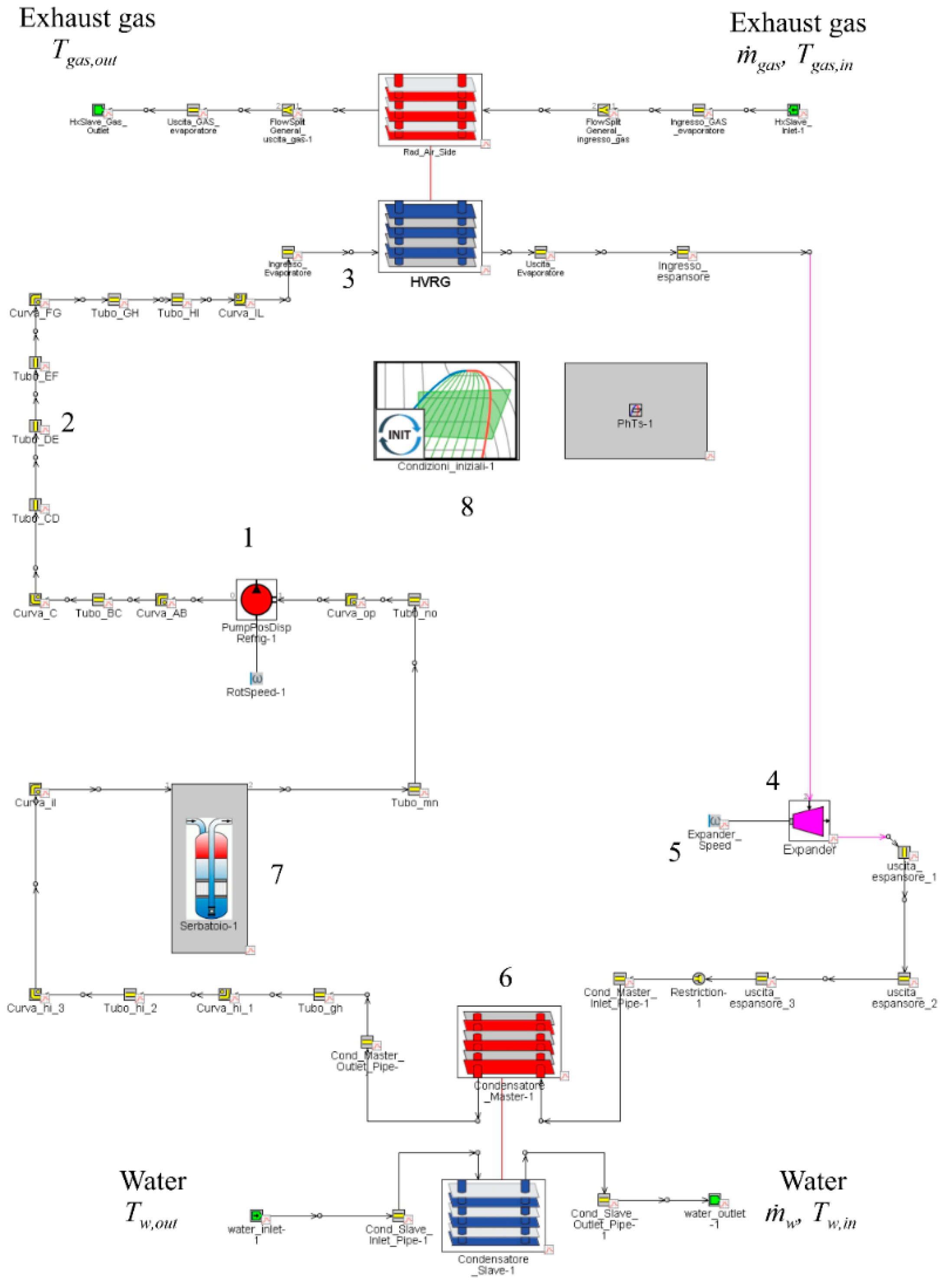
  • Component #1 represents the gear pump, which is modeled as a single component characterized by its volumetric capacity and thermodynamic performance, i.e., the volumetric and adiabatic isentropic efficiency. The present work is based on the data obtained from an extensive experimental campaign by the authors [8], but in the most general case, it can be retrieved from a comprehensive model of the machine, which confirms the versatility of the present approach. The pump revolution speed is varied through an inverted mounted on an asynchronous electric motor. Thus, being a volumetric machine, if the revolution speed, ωpmp, is set, the mass flow rate circulating inside the plant, WF, the pump volumetric efficiency, ηpmp, and the pump intake volume, Vin,pmp, are known. The pump was modeled as in Equation (1):
    m ˙ WF = V in , pmp ρ in , pmp η pmp ω pmp 60
    where WF depends on the density of the working fluid at the pump intake ρin,pmp, which is set by the heat sink conditions, ωpmp is an operating condition introduced as an input parameter, Vin,pmp depends on the pump design, and ηpmp depends on the volumetric losses, and it can be either introduced as an experimental map (as in the present paper) or calculated by means of a dedicated model, such as the one developed by the authors in previous work [51].
  • Component #2 is the pipe-template that models the pipe connection of the power plant. In order to reproduce the real hydraulic behavior of the plant in terms of permeability, the real pipe layout is reproduced. To do this, a huge number of pipe elements are involved to reproduce the pipe connections, and each pipe bland and diameter variation is taken into account as well as the material and the surface roughness. For these elements, 1D analysis characterizes the thermo-fluid-dynamic behavior of the working fluid inside the plant, by discretizing the pipes into sub-volumes and by solving balance equations inside each sub-domain in terms of mass conservation (Equation (2)), momentum conservation (Equation (3)), and energy conservation (Equation (4)). These equations are written in 1D, assuming a uniform value for all the quantities in the cross-sectional area of each duct. The fluid-dynamic model is solved through a preliminary linear discretisation of the ducts. Thus, the whole system is subdivided into multiple sub-volumes in contact with each other enclosing a portion of the working fluid. The scalar physical quantities such as pressure, temperature, density, and internal energy are assumed constant within each volume, while the vectorial quantities such as fluid speed and mass flow rate are evaluated on each interface. An implicit method is employed for the integration of the differential equations in order to obtain a simultaneous solution for all the sub-volumes at a certain time step. In this method, the primary variables are the mass flow rate, pressure, and the total enthalpy [52].
    d m d t = m ˙
    d m ˙ d t = d ρ u A d t = d p A + m ˙ u 4 C f ρ u | u | 2 d x A D K p ( 1 2 p u | u | ) A d x
    d ρ h V d t = m ˙ h + V d p d t δ A s ( T f l u i d T w a l l )
    The model allows a physical representation of the ORC based-power plant and the reproduction of its hydraulic behavior, by assessing the effect on the plant permeability of each component and functional connections. As a matter of fact, the permeability α (Equation (5)) can be defined as the ratio of the mass flow rate and pump pressure rise:
    α = m ˙ WF p
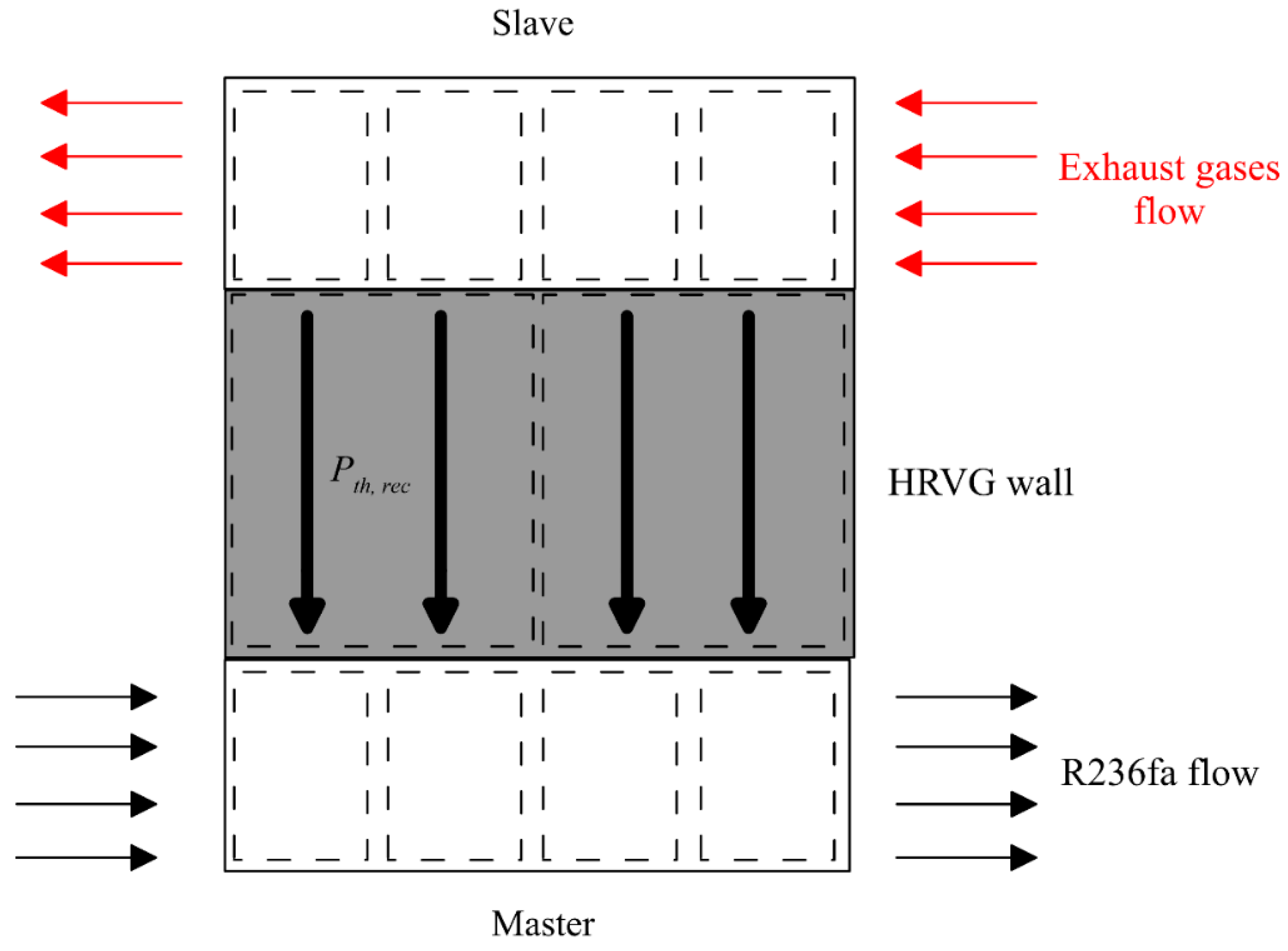
  • Component #3, which is the evaporator, is modeled according a master-slave hierarchy, with the cold side of the evaporator (working fluid side) mastering and the exhaust side acting as the slave. The division in the master and slave section is only a mathematical abstraction, according to which one flow passes through the master and the other passes through the slave. However, the master and the slave together represent the whole behavior of the evaporator accounting for the geometry of the real machine, which eventually allows a proper assessment of both the thermal inertia of the metallic masses and the pressure drops inside.
In the master–slave approach reported in Figure 6, the HRVG walls are sub-divided into 60 sub-volumes, and for each time step, the solver evaluates the thermal energy exchanged between the exhaust gases and working fluid Pth,rec. The model considers heat transfer as the combination of two contributions, one related to the thermal conduction through the HRVG wall and the other related to the convective heat exchange between each fluid and the adjacent HRVG wall. The thermal power exchanged Pth,rec is evaluated according to Equation (6):
P th , rec = U A s Δ T
where:
  • As represents the area of heat exchange determined by the model for each sub-volume as a function of HRVG geometry introduced as a calculation input;
  • ΔT is the temperature logarithmic mean difference between each fluid evaluated as a function of the HRVG configuration;
  • U represents a whole convective heat exchange coefficient evaluated at each analysis step and for each sub-volume based on the condition of fluid motion, its thermophysical properties, and the roughness of the duct surfaces. The product UAs is evaluated from:
U A s = 1 ( 1 U m A m + t w k w A w + 1 U sl A sl )
where Usl and Um represent respectively the convective heat exchange between the exhaust gas and the HRVG wall (slave), and between the HRVG wall and working fluid (master), Asl and Am are the corresponding master and slave heat exchange surfaces, kw represents the conductive thermal conductibility of the HRVG wall, AW is the surface of the conductive heat exchange area, and tW is the thickness of the HRVG wall. The heat exchange coefficients are evaluated according to specific correlations applied to each sub-volume of the evaporator: when the solver determines that the working fluid is in the single-phase state (either liquid or vapor), the Colburn correlation is used [52], whilst for the two-phase state, the Plate-Kandlikar correlation [52] applies.
Concerning the input required by this section, the exhaust gases’ mass flow rate and temperature are set as boundary conditions, while the working fluid mass flow rate is imposed by the pump and from the condition at the intake.
4.
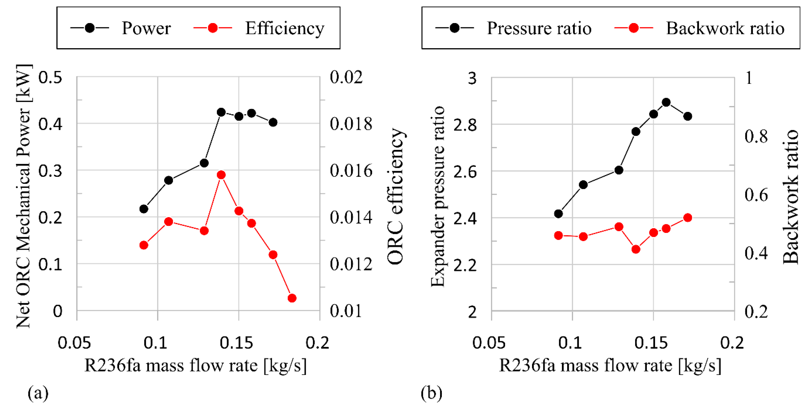
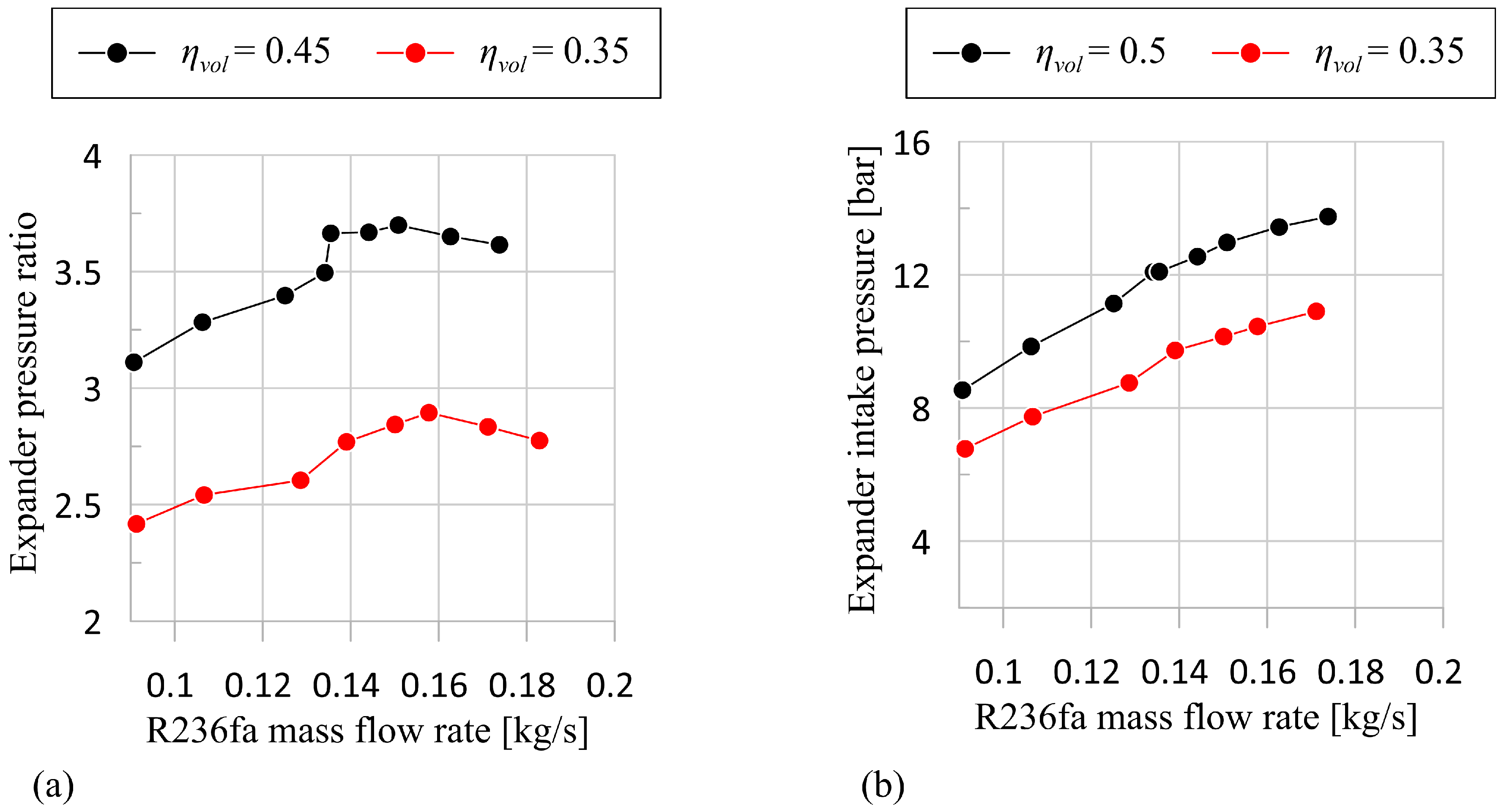
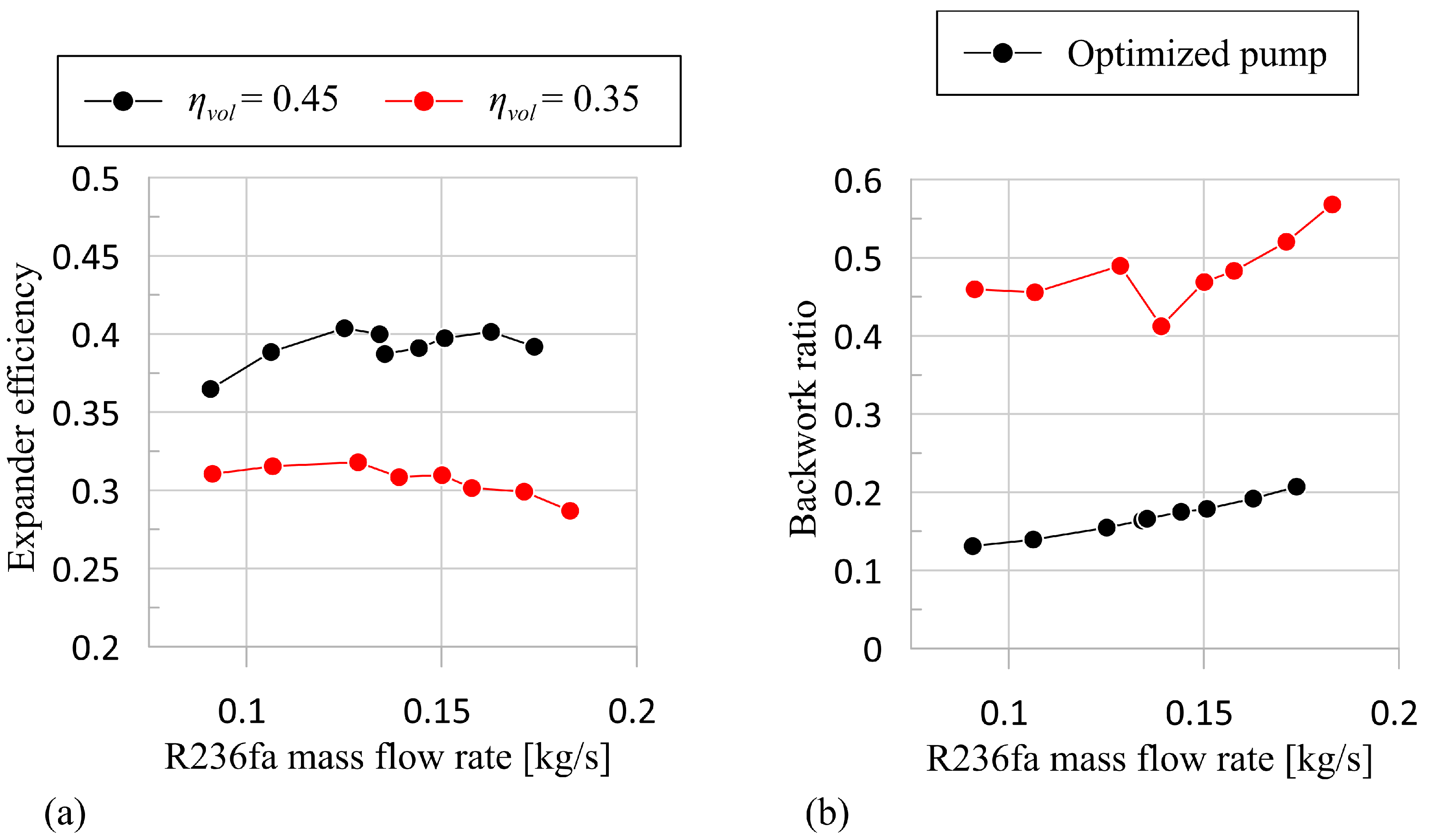
Component #4 represents the SVRE whose characteristics are introduced as a look-up-table. The introduced data can be obtained from an expander model as the one developed by the authors in previous studied [8] or from the specific experimental campaign, [8]. The required data are the revolution speed, the mass flow rate entering the machine, the mechanical power produced, and the intake and exhaust pressure and temperature. The use of the table is necessary because the software environment does not conceive of introducing the specific model of the SVRE [8] inside the whole model. This is because in the SVRE model, the evaluation proceeds over time periodically, while the calculation proceeds in a continuous way. Anyway, the expander model allows defining the relation between the pressure ratio β (Equation 8) across the expander and its performance in terms of power and efficiency. The expander pressure ratio is defined, dividing the expander intake pressure by the pressure exerted by the circuit at the expander outlet. This value represents the pressure difference at which the machine operates. The higher the ratio, the larger the power producible by the SVRE. Therefore, this parameter can be certainly indicative of the suitability of the machine for the considered application. Another aspect to be taken into account is the impact of pump power on that produced by the expander from a net ORC plant power point of view. This ratio is called the backwork ratio, BWR, and it is reported in Equation 9. The model ensures the evaluation of BWR as both the pump and expander power are predicted.
β = p EXP , in p EXP , out
BWR = P pmp P EXP
When volumetric expanders are considered, another fundamental parameter is the built-in volume ratio, which is defined by dividing the exhaust volume by the intake volume:
VR = V exh V suc
The value of VR (Equation (10)) in a volumetric machine is fixed and defines the pressure inside the expander chamber when the exhaust port opens. This value can be different from the pressure imposed by the circuit at expander outlet, pEXP,out, so in the machine design, the VR should be properly defined to match the considered application.
Indeed, if VR is not properly sized, it affects the indicated power Pind, which is defined in Equation (11) as the integral of the p-V diagram that reports the pressure inside the expander chamber as a function of its volume. Consequently, if Pind diminishes, the mechanical power Pmech decreases also, as it can be evaluated in Equation (12) as the difference between Pind and the power loss due to friction Ploss. Concerning this latter quantity, in SVRE, it coincides with the dry friction power due to the relative motion of the blade tip on the stator inner surface.
P ind = i = 1 N v p i d V i t cycle
P mech = P ind P loss
η vol = m ˙ th m ˙ WF = ρ in , end V in , end N v ω   m ˙ WF
The power produced by the machine depends also on volumetric efficiency evaluated in Equation (13) as the ratio between the theoretical mass flow rate aspirated by the SVRE and the real one that enters the machine. The difference is due to the leakages that flow across the clearance gap (between the blade tip at the stator inner surface, between the rotor face and casing, and between the blade side and rotor slot).
5.
Component #5 represents the electric generator that was introduced as a boundary condition in terms of the rotational speed at which the SVRE rotates as a consequence of the dynamic equilibrium on the expander shaft. If the generator is connected to the electric network (as in the experimented case), the velocity is constant. Nevertheless, if a proper inverter was installed on the expander, the revolution speed at which the expander works can be changed, constituting an important degree of freedom for expander regulation. The model is able to vary the revolution speed, thus catching this phenomenon.
6.
Component #6 is equivalent to Component #5 and represents the condenser. The hot (working fluid) side is the master and the tap water for cooling the slave; the cooling capacity is set by the boundary conditions (flow rate and temperature). Similarly to the evaporator, the machine is physically represented and the Dittus–Boelter correlation [52] applies to the single-phase flow region (liquid or vapour), and the Plate, Yan, Lio, and Lin correlations [52] apply to the two-phase region.
7.
Component #7 allows modeling the tank located upstream from the pump. This element allows varying the volume capability and consequently the volume of the whole plant. In the post processing, this element allows also understanding the phase of the working fluid inside the plant.
8.
Component #8 is the holder of the data initialization as the charge and the temperature and pressure of working fluid. In particular, the charge of the working fluid can be varied in order to predict the effect on plant performance if a different quantity of working fluid is charged in the plant. Thanks to this component, the model can be retained as charge sensitive. For the experimental case considered, the mass of the working fluid charged inside the plant is 6.5 kg.

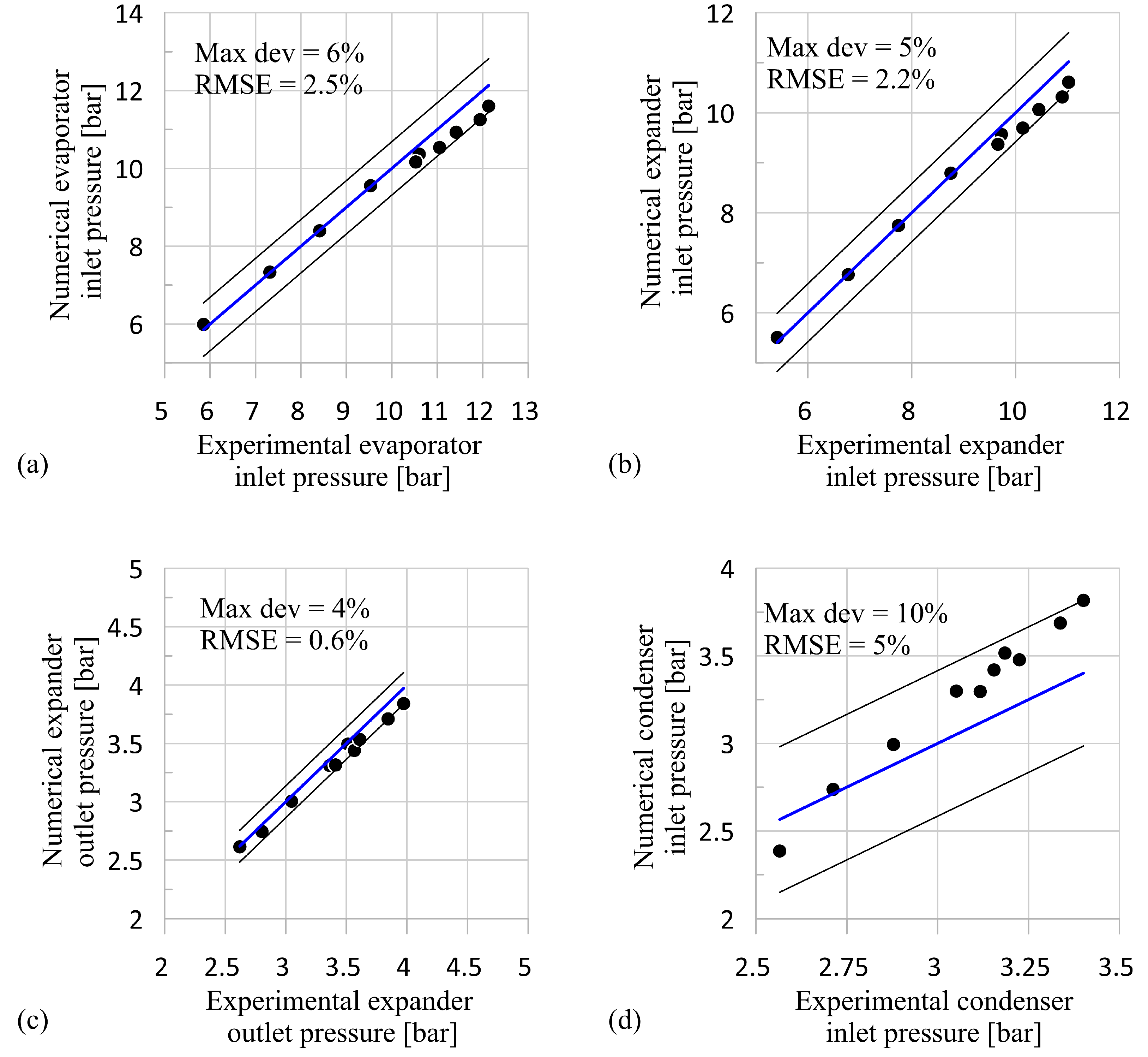
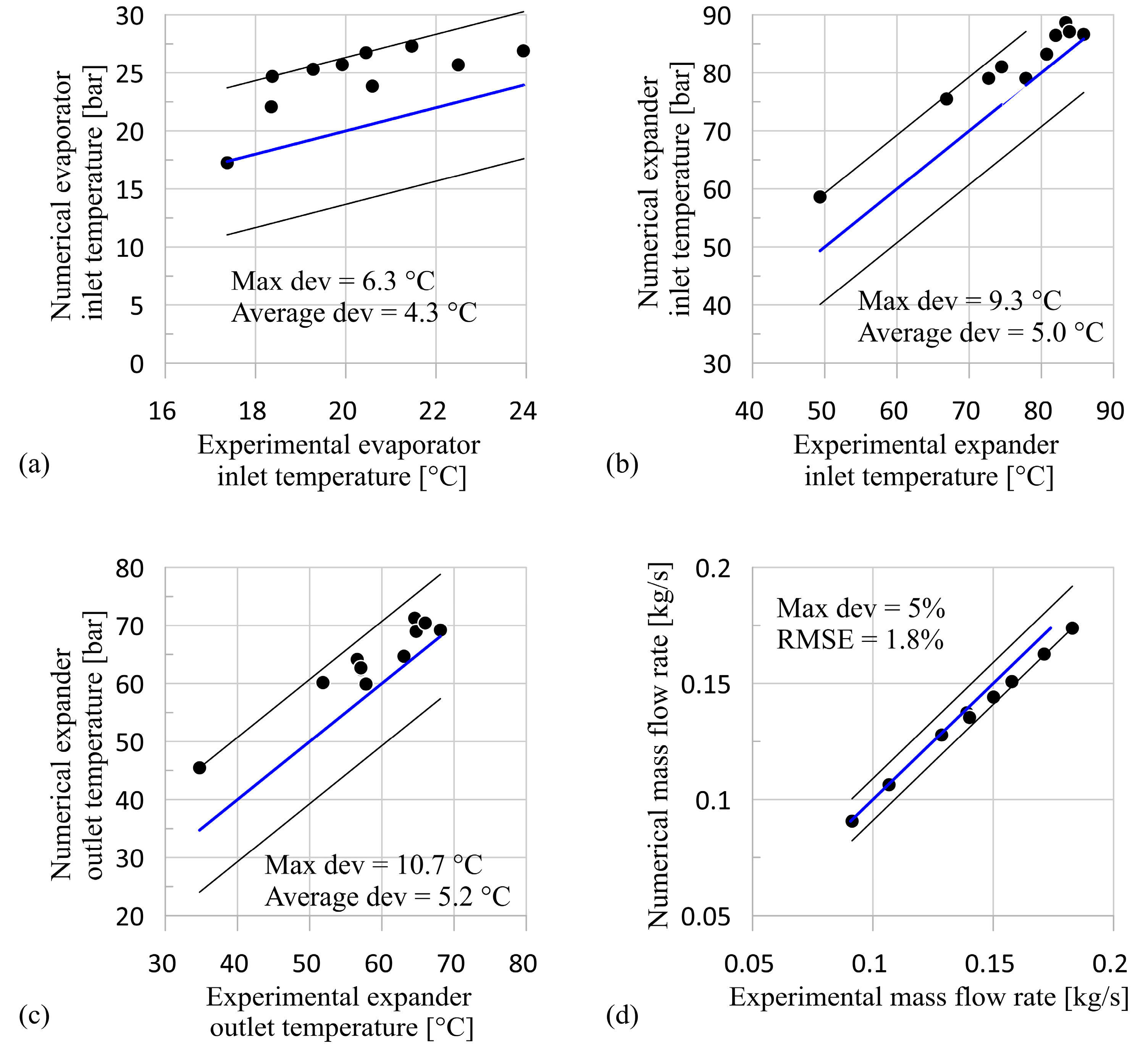
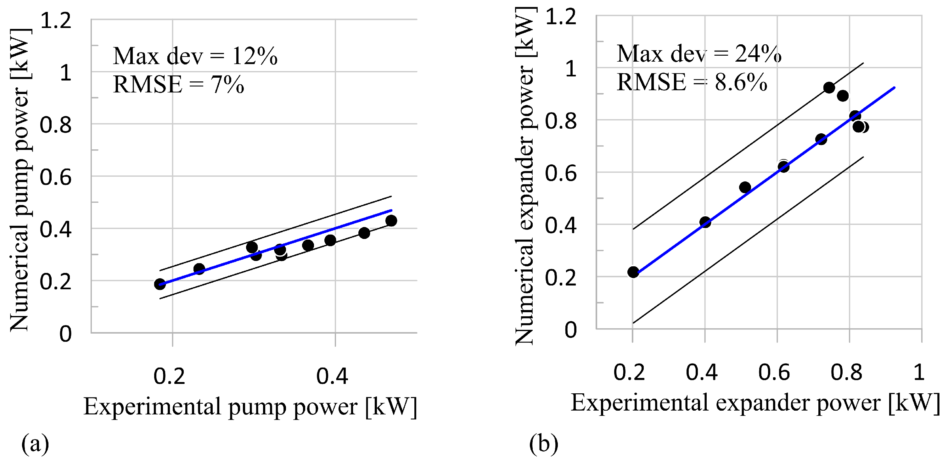
2.3. Experimental Validation

The model validation is carried out using the data from an extensive experimental campaign conducted on the test rig reported in Figure 1. Thus, fixing the following boundary conditions:
  • Mass flow rate sent by the pump. The first parameter is fixed once the revolution speed was defined, in fact, being the pump of a volumetric pipe, in this case, the mass flow rate is known.
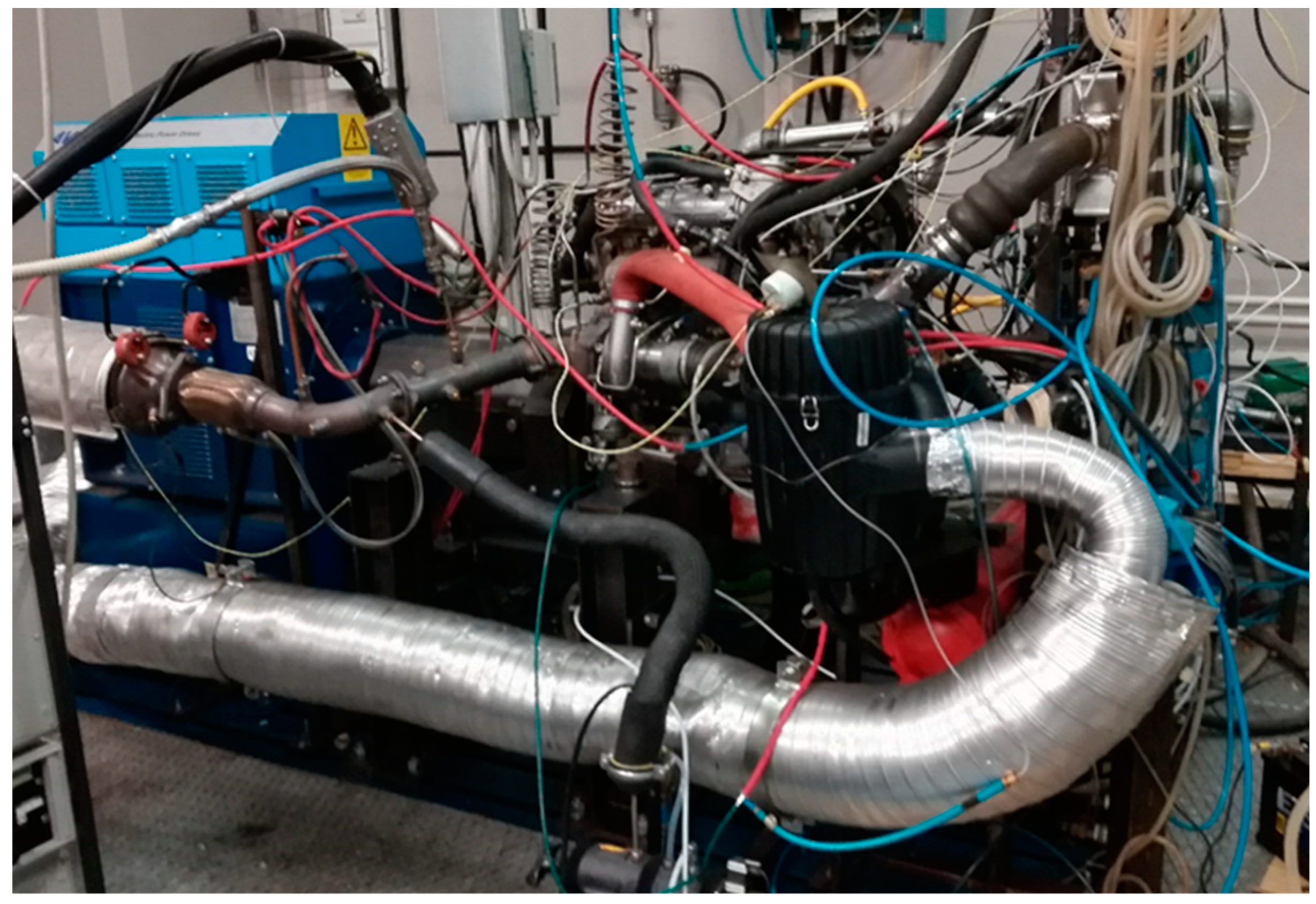
  • Mass flow rate and temperature of exhaust gas at the evaporator inlet. This information is related to the operating point of the ICE as it depends on its torque and the revolution speed. In the validation procedure, they are measured on the ICE dynamic test bench, which allows reproducing the real operating conditions encountered by the vehicle. In this way, the ORC plant can be tested for a wide variation of the high thermal source, and its performance can be evaluated under off-design conditions.
  • Expander revolution speed. This condition can be entered through Component #5 and depends on the dynamic equilibrium at the expander shaft. As mentioned previously, if the expander is connected to the electric network, this speed is fixed, while if an inverter is employed, the velocity can be changed. It is worth noting that the expander reaches a certain operating condition quickly because the dynamics of the expander are fast relative to the other components.
  • Mass flow rate and temperature of the coolant at the condenser inlet. This information defines the heat sink. In the experimental case considered, there is a pump that circulates the cooling water with a mass flow rate equal to 1.5 kg/s at a temperature of 15–25 °C.
  • Charge of working fluid inside the plant. The mass of working fluid is introduced in Component #8 together with the initial temperature and pressure of the working fluid.
The inlet and outlet pressure and temperature of the working fluid at the evaporator, expander, and condenser are predicted and compared to the experimental data. The mechanical power at the expander and pump shaft are predicted and compared with the measured data.
Figure 7 shows the errors in the pressure at the evaporator inlet (Figure 7a), expander inlet (Figure 7b), expander outlet (Figure 7c), and condenser inlet (Figure 7d). The model allows capturing the hydraulic behavior of the power plant, with a deviation and a root mean square error (RMSE) below 10% and 5%, respectively. Furthermore, the model is able to represent with satisfying accuracy the temperature at the evaporator inlet (Figure 8a), at the expander inlet (Figure 8b), and at the expander outlet (Figure 8c). Indeed, as it can be observed from Figure 5, the average absolute deviations are respectively 4.3 °C for the evaporator inlet temperature, 5.0 °C for the expander inlet temperature, and 5.2 °C for the expander outlet temperature. It is worth noticing that the condenser inlet temperature was not reported, since it is quite coincident with the expander outlet temperature. Figure 8d shows the accuracy of the working fluid mass flow rate prediction, with a 5% maximum deviation and a 1.8% RMSE. The low errors in terms of the mass flow rate (Figure 8d) and pressure upstream and downstream of the main components (Figure 7) demonstrate the model’s ability to represent the real hydraulic behavior of the plant. Indeed, according to Equation (5), the permeability is defined as the pressure in correspondence of a certain component for a given mass flow rate circulating inside the plant. The model reproduces the mechanical power needed by the pump to process the working fluid (Figure 9a) and the one produced by the expander (Figure 9b) with an RMSE equal to 7% and 8.6%, respectively. On the other hand, the maximum deviation is equal to 12% and 24%, respectively.

3. Results: Analysis of the Recovery Plant Performance and Optimization

3.1. Baseline ORC-Based Power Plant Performance Analysis

Once validated, the model is used to optimize the whole performance of the ORC plant (Figure 6). The net mechanical power output of the ORC plant in Figure 10a, i.e., the difference between the expander output and the power consumption by the pump, varies between 0.20 and 0.42 kW when the working fluid mass flow rate is in the range of 0.09 to 0.18 kg/s. The ORC plant maximum power and maximum energy efficiency occur with a mass flow rate of 0.14 kg/s (Figure 10a), despite a relatively average (2.75) value of the expander pressure ratio. Indeed, regarding this mass flow rate, the backwork ratio BWR (Equation 9) is at its lowest (0.2), producing the maximum energy response for the plant (Figure 10b). Even if higher expander pressure ratios correspond to the higher mechanical power generated by the expander, they also produce a higher BWR, i.e., an increased demand of pump power, leading to lower net power output. Prior to any optimization effort, the parameters on which the expander intake and outlet pressures depend should be assessed, as they determine the net recovered mechanical power. As aforementioned, a volumetric expander has a fixed built-in volume ratio (VR) (Equation (10)) given by the ratio between the exhaust and intake volume.
Experimental evidence suggests that for given intake conditions (i.e., pressure and temperature), the vane pressure at the exhaust port opening hardly matches the fluid one at the expander outlet.
The experimental indicated cycle in Figure 11a shows an overexpansion with respect to the circuit pressure, pexh, which leads to an isochoric recompression of the working fluid at the exhaust start and eventually to a lower indicated mechanical power. Thus, the term overexpansion means that the pressure of the fluid at the exhaust port opening is lower than that imposed by the fluid. The rated case is in Figure 11b, with the pressure inside the vane at the exhaust start closely matching the circuit one. For the same convention used to define the overexpansion, the under-expansion occurs when the pressure inside the chamber is higher than that in the circuit, as shown in Figure 11c, where an expansion at constant volume (isochoric) takes place, resulting in a larger value of indicated power.
Then, subtracting the friction-related mechanical losses, i.e., dry friction associated with the blades–stator relative motion, in SVRE [8] according to Equation (12), 743, 350, and 200 W mechanical power is assessed, in the scenarios in Figure 11c, Figure 11b, and Figure 11a, respectively.
This highlights the importance of the pressure ratio across the expander, i.e., the proper matching of the vane and line pressures for reduced penalty on the recovered mechanical power. As a matter of fact, when a volumetric expander is used, apart from the clearance gap that bypasses the inner chamber of the expander, there is no communication between the high-pressure line (from pump exhaust to expander intake end) and the low-pressure line (from the expander exhaust start to pump intake). Thus, the maximum pressure and the minimum pressure can be considered independent [8].
The maximum pressure depends on the expander permeability, which is a function of the volumetric efficiency and the expander revolution speed: the higher the permeability, the lower the intake pressure for a fixed mass flow rate. For a given revolution speed, the intake pressure increases with a linear trend as a function of the mass flow rate, as shown in Figure 12a, which shows that the expander permeability determines the ORC-based power unit maximum pressure.
Figure 12b reports the pressure at the condenser inlet and pump intake: both pressures grow linearly with the mass flow rate but with a lower slope than the intake pressure, as a consequence of the differences on the pressure losses.
The higher pressure in the condenser—and consequently, at the pump intake—is due to the temperature of the water employed as the cooling medium. Figure 13a indicates that the temperature of R236fa at the condenser outlet is close to the water temperature across the condenser. As the mass flow rate increases, more power is recovered by the working fluid, and the heat rejected into the water stream increases, resulting in a higher temperature of the cooling medium at the condenser outlet (Figure 13b). Consequently, once the conditions of the low thermal source are set, the exhaust pressure is only slightly affected by the thermal power recovered by the working fluid. On the contrary, the maximum pressure can be easily changed through the variation of expander permeability, which shows a higher hydraulic impendence than any other component.

3.2. ORC-Based Power Plant Performance Optimization Strategies

The reduction of the expander permeability is certainly one promising solution to optimize the ORC plant performance. Indeed, a lower permeability ensures a higher intake pressure (and consequently a higher β) for a certain mass flow rate of working fluid. The permeability decrease can be obtained using a device with a higher volumetric efficiency, expressed as in Equation (13).
In addition to the selection of a proper volumetric efficiency for the expander, a second possibility for performance enhancement comes from the pump optimization, in order to reduce the BWR [51] or from the adoption of a less permeable expander [53]. In the case at hand, half the power produced by the expander is consumed by the pump. Indeed, the pump suffers from lower efficiency, as it is not optimized for application that involves the use of organic fluid, but it coincided for oleo-dynamic application.
Nonetheless, even if a dedicated pump was employed, a large loss can also be expected. Moreover, if the expander is less permeable, a lower mass flow rate is needed to reach the design intake pressure, which in turn leads to lower pump power absorption and lower BWR.
Based on previous results, the SVRE expander with higher volumetric efficiency ηvol = 0.45 substitutes for the more permeable one. The new expander has the same geometry but a smaller clearance gap at the tip blade with respect to the previous expander version. In the new machine, the clearance gap is equal to 85 μm, while in the more permeable version, the gap is larger than 140 μm. This difference is caused by the quality of the internal components surface (blade, stator, rings) and the lubrication rate, which is equals in both cases (5% of the whole working fluid charge). The fully experimental comparison between the two machines is reported in Ref. [8].
In Figure 14a, the permeability decrease with the new machine is appreciated. Indeed, for a certain mass flow rate elaborated by the machine, the new expander guarantees a higher pressure ratio β as a consequence of a larger intake pressure at the expander inlet, which is due to the lower permeability of the new device (Figure 14b). Indeed, if the device has high permeability keeping constant the mass flow sent by the pump, only a small part of working fluid enters the expander chamber, while the remaining part escapes as leakage flows.
Thus, the mass enclosed in the chamber defines a pressure lower than that achievable if the leakage was lower (machine with a higher volumetric efficiency and less permeable). Furthermore, as the volumetric losses are the main limit of the whole expander performance growth, if the flow leakage diminishes by the adoption of a less permeable device, higher expander efficiency values can be achieved (Figure 15a).
On the other hand, the pump optimization is associated with a BWR increase from 0.14 to 0.2, when the mass flow rate doubles, from 0.09 to 0.18 kg/s (Figure 15b). Thus, the impact of pump power on that produced by the expander is halved with respect to the experimental case. The reason is that if the expander and consequently the circuit is more permeable, the pump must pressurize a higher quantity of working fluid, but this extra mass flow rate does not enter the expander, being associated to leakage.
Hence, the benefits expected on the expander pressure ratio (and expander power) are not achieved, and the BWR increases. However, this information suggests new avenues and new concepts for ORC plant optimization. Indeed, the pump is in most cases neglected, but its improvement ensures largely enhancing the ORC plant performance. Volumetric machines in this sense show high potential being less sensitive to revolution speed variation than the dynamic ones.
Both these optimization strategies lead to an improvement of ORC performance in terms of net power produced (Figure 16a) and efficiency (Figure 16b). A maximum net power of 1.05 kW can be recovered, i.e., 50% gain with respect to the maximum power in the baseline case. Moreover, it can be observed that the net recovered power does not grow with the mass flow rate indefinitely: a mass flow rate of 0.18 kg/s allows the maximum power recovery. The same advantages are appreciated on the ORC efficiency that ranges between 3.0% and 3.5% (at 0.09 and 0.15 kg/s, respectively).
Hence, there is a trade-off between the operating conditions, in terms of mass flow rate, for net ORC power and plant efficiency maximization that should be sought. Nonetheless, both the power and efficiency curves show a flat trend in correspondence of the maximum: satisfyingly high performances can be reached for a wide mass flow rate range.

4. Further Discussion

The adoption of the proposed optimization strategies has been shown to increase the net thermal efficiency of the ORC plant investigated in this work, on average, from 1.5% to 3.5% and the maximum generated power from 400 to 1100 W, respectively. The performance of the ORC plant in the present work was comparable to that performance of ORC plants in similar applications by various investigators, which has been experimentally assessed and reported in the literature. For example, in Ref. [54], an ORC plant with an intermediate oil circuit and radial turbine achieved an efficiency of 4% with a turbine efficiency of 35%. In Ref. [55], a swash-plate expander was adopted, and the ORC plant reached an efficiency of 6% with an expander efficiency of 38% when recovering heat from a 2-L ICE. Furthermore, the ORC plant developed and reported in Ref. [56] adopting a single-screw expander was demonstrated to have an efficiency of up to 6.3%, while the expander reached an efficiency of 58%, and an ORC plant recovering heat from a 3-L diesel engine reached an efficiency of up to 4% when employing a scroll expander [53]. In the application considered in Ref. [57], which involves the adoption of a 190 W sliding vane expander, the ORC plant efficiency was 1.6%. Thus, despite the efficiency and power produced by the optimized ORC plant being in these performance ranges, there is still room for plant performance improvement, which rests on improved pump and expander design according the optimization criteria found in this work.

5. Conclusions

ORC plants for the waste heat recovery of internal combustion engine exhaust gases are characterized by severe off-design working conditions due to the intrinsic unsteady behavior of the high and low thermal sources. For this reason, a reliable mathematical model that allows predicting the off-design behavior of the plant is fundamental to define the optimization strategy for the ORC system development. Nevertheless, ORC plants are very complex systems; thus, all the real components and plant features should be considered to obtain reliable results. In order to reach this objective, in this paper, a comprehensive model of an ORC power plant was developed, merging the plant and the thermodynamic analysis of the system. The model was validated based on an extensive experimental campaign on an ORC plant for heat recovery from the exhaust gases of a supercharged 3-L diesel IVECO F1C engine. The accuracy of simulated pressures predicted by the combined 0-D/1-D GT-Suite™ model is found to be within 2% in terms of the maximum RMSE and up to 5–10% in terms of the maximum deviation from the measured pressures. Furthermore, the average absolute error on the simulated temperatures is within the range of 5–6 °C, with a maximum deviation within 9 °C. The pump and expander power are reproduced with a 7% and 8.6% RMSE, respectively.
The validated model served as a computational design platform for assessing the benefits on the net power and efficiency of the plant, which are associated with (i) a lower expander permeability; and (ii) the benefits of sliding vane rotary pump optimization. A lower permeability was found to increase the pressure ratio at the expander for a given mass flow rate and, consequently, the expander power. An additional advantage is associated with the higher volumetric performance of the expander. An optimized pump can allow a lower pumping power requirement and eventually lead to a lower backwork ratio (50% lower than the one in the baseline case). These optimization strategies are developed thanks to a novel concept of plant modeling. In fact, the new approach aims to integrate the cycle and plant analysis, thus reproducing the real phenomena taking place in the plant due to the components and pipes layout employed. The combination of these strategies can increase the ORC plant net power and efficiency by up to 50% compared with the baseline case.

Author Contributions

Conceptualization, R.C., C.N.M., F.F., D.V., Y.W., J.S.; methodology, R.C., C.N.M., F.F., D.V., Y.W., J.S.; software, F.F.; validation, F.F., D.V.; formal analysis, R.C., C.N.M., F.F., D.V., Y.W., J.S.; investigation, R.C., C.N.M., F.F., D.V., Y.W., J.S.; resources, R.C., C.N.M.; data curation, F.F., D.V.; writing—original draft preparation, R.C., C.N.M., F.F., D.V., Y.W., J.S.; writing—review and editing, R.C., C.N.M., F.F., D.V., Y.W., J.S.; visualization, R.C., C.N.M., F.F., D.V., Y.W., J.S.; supervision, R.C., C.N.M.; project administration, R.C., C.N.M. All authors have read and agreed to the published version of the manuscript.

Funding

This research received no external funding.

Acknowledgments

This work was supported by the UK Engineering and Physical Sciences Research Council (EPSRC) [grant numbers EP/P004709/1, and EP/R045518/1]. Data supporting this publication can be obtained on request from cep-lab@imperial.ac.uk. This research work was developed in the framework of the National Operating Program (PON) for Attraction and International Mobility (AIM) - AIM1829299, a project of the Italian Ministry of University (MIUR) to favour the international research collaboration.

Conflicts of Interest

The authors declare no conflict of interest.

Nomenclature

SymbolsSubscripts
A—area [m2]Exh—exhaust
BWR—backwork ratioEXP—expander
Cf—fanning friction coefficientgas—exhaust gas
D—diameter [mm]in—inlet/intake
dx—discretization length [mm]ind—indicated
dVi—chamber volume variation [m3]loss—mechanical losses
HRVG—heat recovery vapour generatorm—master
h—specific total enthalpy [J/kg]mech—mechanical
k—thermal conductivity [W/mK]out—outlet
Kp—pressure drop coefficientpmp—pump
m—mass [kg]s—heat exchange area [m2]
—mass flow rate [kg/s]sl—slave
P—power [W]suc—suction
p—pressure [Pa, bar]vol—volumetric
PHX—plate heat exchangerw—water
Nvnumber of vanes/bladeswall—wall temperature
tcycle—cycle time [s]WF—working fluid
T—temperature [K, °C]
t—thickness of HRVG wall [mm]Greek Letter
U—whole heat transfer coefficient [W/m2K]
Ummaster convective coefficient [W/m2K]α—permeability
Usl—master convective coefficient [W/m2K]Δp—pressure difference [bar]
u—speed [m/s]δ—heat transfer coefficient [W/m2K]
V—volume of sub-element [m3]η—efficiency
VR—volume ratioρ—density
ω—expander revolution speed [RPM]/[RPS]

References

  1. Wang, T.; Liu, L.; Zhu, T.; Gao, N. Experimental investigation of a small-scale organic Rankine cycle under off-design conditions: From the perspective of data fluctuation. Energy Convers. Manag. 2019, 198, 111826. [Google Scholar] [CrossRef]
  2. Santos, M.; André, J.; Francisco, S.; Mendes, R.; Ribeiro, J. Off-design modelling of an organic Rankine cycle micro-CHP: Modular framework, calibration and validation. Appl. Therm. Eng. 2018, 137, 848–867. [Google Scholar] [CrossRef]
  3. He, Z.; Zhang, Y.; Dong, S.; Ma, H.; Yu, X.; Zhang, Y.; Ma, X.; Deng, N.; Sheng, Y. Thermodynamic analysis of a low-temperature organic Rankine cycle power plant operating at off-design conditions. Appl. Therm. Eng. 2017, 113, 937–951. [Google Scholar] [CrossRef]
  4. Mahmoudi, A.; Fazli, M.; Morad, M.R. A recent review of waste heat recovery by organic Rankine cycle. Appl. Therm. Eng. 2018, 143, 660–675. [Google Scholar] [CrossRef]
  5. Shi, L.; Shu, G.; Tian, H.; Deng, S. A review of modified organic Rankine cycles (ORCs) for internal combustion engine waste heat recovery (ICE-WHR). Renew. Sustain. Energy Rev. 2018, 92, 95–110. [Google Scholar] [CrossRef]
  6. Wang, Z.; Hu, Y.; Xia, X.; Zuo, Q.; Zhao, B.; Li, Z. Thermo-economic selection criteria of working fluid used in dual-loop ORC for engine waste heat recovery by multi-objective optimization. Energy 2020, 197, 117053. [Google Scholar] [CrossRef]
  7. Le Brun, N.; Simpson, M.; Acha, S.; Shah, N.; Markides, C.N. Techno-economic potential of low-temperature, jacket-water heat recovery from stationary internal combustion engines with organic Rankine cycles: A cross-sector food-retail study. Appl. Energy 2020, 274, 115260. [Google Scholar] [CrossRef]
  8. Fatigati, F.; Di Bartolomeo, M.; Cipollone, R. Experimental and numerical characterization of a positive displacement vane expander with an auxiliary injection port for an ORC-based power unit. Energy Procedia 2018, 148, 830–837. [Google Scholar] [CrossRef]
  9. Fatigati, F.; Di Bartolomeo, M.; Di Battista, D.; Cipollone, R. Experimental and Numerical Characterization of the Sliding Rotary Vane Expander Intake Pressure in Order to Develop a Novel Control-Diagnostic Procedure. Energies 2019, 12, 1970. [Google Scholar] [CrossRef] [Green Version]
  10. Dickes, R.; Dumont, O.; Guillaume, L.; Quoilin, S.; Lemort, V. Charge-sensitive modelling of organic Rankine cycle power systems for off-design performance simulation. Appl. Energy 2018, 212, 1262–1281. [Google Scholar] [CrossRef]
  11. Quoilin, S. Sustainable Energy Conversion through the Use of Organic Rankine Cycles for Waste Heat Recovery and Solar Applications. Ph.D. Thesis, University of Liège, Liège, Belgium, 2011. [Google Scholar]
  12. Manente, G.; Toffolo, A.; Lazzaretto, A.; Paci, M. An organic Rankine cycle off-design model for the search of the optimal control strategy. Energy 2013, 58, 97–106. [Google Scholar] [CrossRef]
  13. Wang, J.; Yan, Z.; Zhao, P.; Dai, Y. Off-design performance analysis of a solar-powered organic Rankine cycle. Energy Convers. Manag. 2014, 80, 150–157. [Google Scholar] [CrossRef]
  14. Hu, D.; Zheng, Y.; Wu, Y.; Li, S.; Dai, Y. Off-design performance comparison of an organic Rankine cycle under different control strategies. Appl. Energy 2015, 156, 268–279. [Google Scholar] [CrossRef]
  15. Gurgenci, H. Performance of power plants with organic Rankine cycles under part-load and off-design conditions. Sol. Energy 1986, 36, 45–51. [Google Scholar] [CrossRef]
  16. Song, J.; Gu, C.W.; Ren, X. Parametric design and off-design analysis of organic Rankine cycle (ORC) system. Energy Convers. Manag. 2016, 112, 157–165. [Google Scholar] [CrossRef]
  17. Möller, A.; Gullapalli, V.S. System cost and efficiency optimization by heat exchanger performance simulations. Energy Procedia 2017, 129, 459–465. [Google Scholar] [CrossRef]
  18. Gullapalli, V.S. Modeling of brazed plate heat exchangers for ORC systems. Energy Procedia 2017, 129, 443–450. [Google Scholar] [CrossRef]
  19. Chatzopoulou, M.A.; Lecompte, S.; De Paepe, M.; Markides, C.N. Off-design optimisation of organic Rankine cycle (ORC) engines with different heat exchangers and volumetric expanders in waste heat recovery applications. Appl. Energy 2019, 253, 113442. [Google Scholar] [CrossRef]
  20. Pantano, F.; Capata, R. Expander selection for an on board ORC energy recovery system. Energy 2017, 141, 1084–1096. [Google Scholar] [CrossRef] [Green Version]
  21. Freeman, J.; Hellgardt, K.; Markides, C.N. An assessment of solar-powered organic Rankine cycle systems for combined heating and power in UK domestic applications. Appl. Energy 2015, 138, 605–620. [Google Scholar] [CrossRef] [Green Version]
  22. Dickes, R.; Dumont, O.; Daccord, R.; Quoilin, S.; Lemort, V. Modelling of organic Rankine cycle power systems in off-design conditions: An experimentally-validated comparative study. Energy 2017, 123, 710–727. [Google Scholar] [CrossRef]
  23. Oyewunmi, O.A.; Taleb, A.I.; Haslam, A.J.; Markides, C.N. On the use of SAFT-VR Mie for assessing large-glide fluorocarbon working-fluid mixtures in organic Rankine cycles. Appl. Energy 2016, 163, 263–282. [Google Scholar] [CrossRef] [Green Version]
  24. Oyewunmi, O.A.; Markides, C.N. Markides, Thermo-economic and heat transfer optimization of working-fluid mixtures in a low-temperature organic Rankine cycle system. Energies 2016, 9, 448. [Google Scholar] [CrossRef] [Green Version]
  25. Oyewunmi, O.A.; Kirmse, C.J.; Pantaleo, A.M.; Markides, C.N. Markides, Performance of working-fluid mixtures in ORC-CHP systems for different heat-demand segments and heat-recovery temperature levels. Energy Convers. Manag. 2017, 148, 1508–1524. [Google Scholar] [CrossRef]
  26. Song, J.; Gu, C.W. Analysis of ORC (Organic Rankine Cycle) systems with pure hydrocarbons and mixtures of hydrocarbon and retardant for engine waste heat recovery. Appl. Therm. Eng. 2015, 89, 693–702. [Google Scholar] [CrossRef]
  27. Ziviani, D.; Woodland, B.J.; Georges, E.; Groll, E.A.; Braun, J.E.; Horton, W.T.; Van den Broek, M.; De Paepe, M. Development and validation of a charge Sensitive organic Rankine cycle (ORC) simulation tool. Energies 2016, 9, 389. [Google Scholar] [CrossRef] [Green Version]
  28. Liu, L.; Zhu, T.; Ma, J. Working fluid charge oriented off-design modeling of a small scale organic Rankine cycle system. Energy Convers. Manag. 2017, 148, 944–953. [Google Scholar] [CrossRef]
  29. Desideri, A.; Amicabile, S.; Alberti, F.; Vitali-Nari, S.; Quoilin, S.; Crema, L.; Lemort, V. Dynamic modeling and control strategies analysis of a novel small CSP biomass plant for cogeneration applications in building. In Proceedings of the SWC 2015/ISES Conference Proceedings, Daegu, Korea, 8–12 November 2015. [Google Scholar] [CrossRef] [Green Version]
  30. Alobaid, F.; Mertens, N.; Starkloff, R.; Lanz, T.; Heinze, C.; Epple, B. Progress in dynamic simulation of thermal power plants. Prog. Energy Combust. Sci. 2017, 59, 79–162. [Google Scholar] [CrossRef]
  31. Vodicka, V.; Novotny, V.; Mascuch, J.; Kolovratnik, M. Impact of major leakages on characteristics of a rotary vane expander for ORC. Energy Procedia 2017, 129, 387–394. [Google Scholar] [CrossRef]
  32. Dickes, R.; Dumont, O.; Lemort, V. Experimental assessment of the fluid charge distribution in an organic Rankine cycle (ORC) power system. Appl. Therm. Eng. 2020, 179, 115689. [Google Scholar] [CrossRef]
  33. Sun, H.; Qin, J.; Hung, T.C.; Huang, H.; Yan, P.; Lin, C.H. Effect of flow losses in heat exchangers on the performance of organic Rankine cycle. Energy 2019, 172, 391–400. [Google Scholar] [CrossRef]
  34. Dumont, O.; Parthoens, A.; Dickes, R.; Lemort, V. Experimental investigation and optimal performance assessment of four volumetric expanders (scroll, screw, piston and roots) tested in a small-scale organic Rankine cycle system. Energy 2018, 165, 1119–1127. [Google Scholar] [CrossRef] [Green Version]
  35. Bianchi, M.; Branchini, L.; Casari, N.; De Pascale, A.; Melino, F.; Ottaviano, S.; Pinelli, M.; Spina, P.R.; Suman, A. Experimental analysis of a micro-ORC driven by piston expander for low-grade heat recovery. Appl. Therm. Eng. 2019, 148, 1278–1291. [Google Scholar] [CrossRef]
  36. Chatzopoulou, M.A.; Simpson, M.; Sapin, P.; Markides, C.N. Off-design optimisation of organic Rankine cycle (ORC) engines with piston expanders for medium-scale combined heat and power applications. Appl. Energy 2019, 238, 1211–1236. [Google Scholar] [CrossRef]
  37. Badr, O.; Probert, S.D.; O’Callaghan, P. Performances of multi-vane expanders. Appl. Energy 1985, 20, 207–234. [Google Scholar] [CrossRef]
  38. Quoilin, S.; Aumann, R.; Grill, A.; Schuster, A.; Lemort, V.; Spliethoff, H. Dynamic modelling and optimal control strategy of waste heat recovery organic Rankine cycles. Appl. Energy 2011, 88, 2183–2190. [Google Scholar] [CrossRef]
  39. Yang, B.; Peng, X.; He, Z.; Guo, B.; Xing, Z. Experimental investigation on the internal working process of a CO2 rotary vane expander. Appl. Therm. Eng. 2009, 29, 2289–2296. [Google Scholar] [CrossRef]
  40. Garg, P.; Karthik, G.M.; Kumar, P.; Kumar, P. Development of a generic tool to design scroll expanders for ORC applications. Appl. Therm. Eng. 2016, 109, 878–888. [Google Scholar] [CrossRef] [Green Version]
  41. Dickson, J.; Ellis, M.; Rousseau, T.; Smith, J. Validation and design of heavy vehicle cooling system with waste heat recovery condenser. SAE Int. J. Commer. Veh. 2014, 7, 458–467. [Google Scholar] [CrossRef]
  42. White, M.T.; Oyewunmi, O.A.; Chatzopoulou, M.A.; Pantaleo, A.M.; Haslam, A.J.; Markides, C.N. Computer-aided working-fluid design, thermodynamic optimisation and thermoeconomic assessment of ORC systems for waste-heat recovery. Energy 2018, 161, 1181–1198. [Google Scholar] [CrossRef]
  43. Emadi, M.A.; Chitgar, N.; Oyewunmi, O.A.; Markides, C.N. Working-fluid selection and thermoeconomic optimisation of a combined cycle cogeneration dual-loop organic Rankine cycle (ORC) system for solid oxide fuel cell (SOFC) waste-heat recovery. Appl. Energy 2020, 261, 114384. [Google Scholar] [CrossRef]
  44. Shu, G.; Wang, X.; Tian, H.; Liu, P.; Jing, D.; Li, X. Scan of working fluids based on dynamic response characters for organic Rankine cycle using for engine waste heat recovery. Energy 2017, 133, 609–620. [Google Scholar] [CrossRef]
  45. Fatigati, F.; Di Bartolomeo, M.; Cipollone, R. Dual intake rotary vane expander technology: Experimental and theoretical assessment. Energy Convers. Manag. 2019, 186, 156–167. [Google Scholar] [CrossRef]
  46. Wang, E.H.; Zhang, H.G.; Fan, B.Y.; Ouyang, M.G.; Zhao, Y.; Mu, Q.H. Study of working fluid selection of organic Rankine cycle (ORC) for engine waste heat recovery. Energy 2011, 36, 3406–3418. [Google Scholar] [CrossRef]
  47. Song, J.; Li, X.; Wang, K.; Markides, C.N. Parametric optimisation of a combined supercritical CO2 (S-CO2) cycle and organic Rankine cycle (ORC) system for internal combustion engine (ICE) waste-heat recovery. Energy Convers. Manag. 2020, 218, 112999. [Google Scholar] [CrossRef]
  48. Mikielewicz, D.; Wajs, J.; Ziółkowski, P.; Mikielewicz, J. Utilisation of waste heat from the power plant by use of the ORC aided with bleed steam and extra source of heat. Energy 2016, 97, 11–19. [Google Scholar] [CrossRef]
  49. Wajs, J.; Mikielewicz, D.; Bajor, M.; Kneba, Z. Experimental investigation of domestic micro-CHP based on the gas boiler fitted with ORC module. Arch. Thermodyn. 2017, 37, 79–93. [Google Scholar] [CrossRef]
  50. Freeman, J.; Hellgardt, K.; Markides, C.N. Working fluid selection and electrical performance optimisation of a domestic solar-ORC combined heat and power system for year-round operation in the UK. Appl. Energy 2017, 186, 291–303. [Google Scholar] [CrossRef] [Green Version]
  51. Bianchi, G.; Fatigati, F.; Murgia, S.; Cipollone, R. Design and analysis of a sliding vane pump for waste heat to power conversion systems using organic fluids. Appl. Therm. Eng. 2017, 124, 1038–1048. [Google Scholar] [CrossRef]
  52. Gamma Technologies. GT Suite, Flow Theory Manual, Flow Solver Basics; Gamma Technologies: Westmont, IL, USA, 2018. [Google Scholar]
  53. Fatigati, F.; Di Bartolomeo, M.; Di Battista, D.; Cipollone, R. Experimental characterization of a hermetic scroll expander operating in an ORC-based power unit bottoming an internal combustion engine. AIP Conf. Proc. 2019, 2191, 020069. [Google Scholar] [CrossRef]
  54. Alshammari, F.; Pesyridis, A. Experimental study of organic Rankine cycle system and expander performance for heavy-duty diesel engine. Energy Convers. Manag. 2019, 199, 111998. [Google Scholar] [CrossRef]
  55. Galindo, J.; Ruiz, S.; Dolz, V.; Royo-Pascual, L.; Haller, R.; Nicolas, B.; Glavatskaya, Y. Experimental and thermodynamic analysis of a bottoming organic Rankine cycle (ORC) of gasoline engine using swash-plate expander. Energy Convers. Manag. 2015, 103, 519–532. [Google Scholar] [CrossRef]
  56. Zhang, Y.Q.; Wu, Y.T.; Xia, G.D.; Ma, C.F.; Ji, W.N.; Liu, S.-W.; Yang, K.; Yang, F.-B. Development and experimental study on organic Rankine cycle system with single-screw expander for waste heat recovery from exhaust of diesel engine. Energy 2014, 77, 499–508. [Google Scholar] [CrossRef]
  57. Suankramdee, W.; Thongtip, T.; Aphornratana, S. Experimental study of a sliding vane expander in a micro-scale ORC system for utilizing low-grade heat. Energy Procedia 2017, 138, 823–828. [Google Scholar] [CrossRef]
Figure 1. Experimental test bench and measurement instruments layout.
Energies 13 05846 g001
Figure 2. Organic Rankine cycle (ORC) plant experimental test bench.
Energies 13 05846 g002
Figure 3. IVECO F1C 3-L supercharged diesel internal combustion engine.
Energies 13 05846 g003
Figure 4. (a) Pump and upstream plenum; (b) heat recovery vapour generator (HRVG); (c) sliding vane rotary expander (SVRE); (d) plate heat exchanger (PHX) condenser.
Energies 13 05846 g004
Figure 5. Diagram of the ORC-based power plant model.
Energies 13 05846 g005
Figure 6. Modeling approach for the HRVG based on the master and slave parameterization.
Energies 13 05846 g006
Figure 7. Comparison between the experimental and predicted pressure at the (a) evaporator inlet; (b) expander inlet; (c) expander outlet; and (d) condenser inlet.
Energies 13 05846 g007
Figure 8. Comparison between the experimental and predicted (a) temperature at evaporator inlet; (b) temperature at expander inlet; (c) temperature at expander outlet; and (d) WF mass flow rate.
Energies 13 05846 g008
Figure 9. Comparison between experimental and predicted mechanical power at: (a) pump; and (b) expander.
Energies 13 05846 g009
Figure 10. (a) Net power produced by ORC and efficiency; and (b) expander pressure ratio and backwork ratio.
Energies 13 05846 g010
Figure 11. SVRE experimental indicated cycle: (a) overexpansion; (b) nominal expansion; and (c) underexpansion.
Energies 13 05846 g011
Figure 12. (a) Evaporator inlet and expander intake pressure; and (b) condenser inlet and pump intake pressure, all as function of the mass flow rate.
Energies 13 05846 g012
Figure 13. (a) R236fa inlet temperature and water inlet and outlet temperature at condenser, (b) Power at low thermal source.
Energies 13 05846 g013
Figure 14. (a) Expander pressure ratio as function of volumetric efficiency; (b) Effect of volumetric efficiency on expander intake pressure.
Energies 13 05846 g014
Figure 15. (a) Efficiency of the two expanders; and (b) backwork ratio of the optimized and current pump.
Energies 13 05846 g015
Figure 16. Net ORC mechanical power and efficiency of the: (a) optimized; and (b) baseline expander.
Energies 13 05846 g016
Table 1. Expander geometry and angle of ports.
Stator Diameter (mm)75.9
Rotor diameter (mm)65
Eccentricity (mm)5.45
Chamber height (mm)60
Blade length (mm)17
Blade tick (mm)3.96
Intake volume (cm3)5.4
Exhaust volume (cm3)19.3
Intake port opening angle (deg)4.4
Intake port closing angle (deg)48
Exhaust port opening angle (deg)180
Exhaust port closing angle (deg)322.5
Table 2. Measurement uncertainty.
Working fluid temperature±0.3 K
Working fluid pressure±0.3 bar
Indicated cycle±0.1% of full-scale sensor output
Working fluid mass flow rate±0.5% (kg/s)
Water mass flow rate±0.5% (kg/s)
Mechanical power±0.8% (W)
Volumetric efficiency±0.6%
Mechanical efficiency±2%
Publisher’s Note: MDPI stays neutral with regard to jurisdictional claims in published maps and institutional affiliations.

