Article

Numerical Modelling and Experimental Verification of the Low-Emission Biomass Combustion Process in a Domestic Boiler with Flue Gas Flow around the Combustion Chamber

1
Faculty of Mechanical Engineering, University of Technology and Humanities in Radom, 26-600 Radom, Poland
2
Faculty of Energy and Environmental Engineering, Silesian University of Technology, 14-100 Gliwice, Poland
3
Faculty of Civil Engineering and Environmental Sciences, Białystok University of Technology, 15-351 Białystok, Poland
4
Faculty of Environmental Engineering and Energy, Poznan University of Technology, 60-965 Poznań, Poland
*
Author to whom correspondence should be addressed.
Energies 2020, 13(21), 5837; https://doi.org/10.3390/en13215837
Submission received: 8 October 2020 / Revised: 29 October 2020 / Accepted: 31 October 2020 / Published: 9 November 2020
(This article belongs to the Special Issue Sustainable Combustion Systems and Their Impact)

Abstract

:
The paper presents the results of numerical and experimental studies aimed at developing a new design of a 10 kW low-emission heating boiler fired with wood pellets. The boiler is to meet stringent requirements in terms of efficiency (η > 90%) and emissions per 10% O2: CO < 500 mg/Nm3, NOx ≤ 200 mg/Nm3, and dust ≤ 20 mg/Nm3; these emission restrictions are as prescribed in the applicable ECODESIGN Directive in the European Union countries. An innovative aspect of the boiler structure (not yet present in domestic boilers) is the circular flow of exhaust gases around the centrally placed combustion chamber. The use of such a solution ensures high-efficiency, low-emission combustion and meeting the requirements of ECODESIGN. The results of the numerical calculations were verified and confirmed experimentally, obtaining average emission values of the limited gases CO = 91 mg/Nm3, and NOx = 197 mg/Nm3. The temperature measured in the furnace is 450–500 °C and in the flue it was 157–197 °C. The determined boiler efficiency was 92%. Numerical calculations were made with the use of an advanced CFD (Computational Fluid Dynamics) workshop in the form of the Ansys programming and a computing environment with the dominant participation of the Fluent module. It was shown that the results obtained in both experiments are sufficiently convergent.

Graphical Abstract

1. Introduction

Excessive CO2 emissions to the atmosphere, the threat of smog (especially in the vicinity of large urban agglomerations), and appropriate legal regulations force the low energy industry to eliminate the use of fossil solid fuels. In the European Union countries, hard coal has almost been eliminated from the market as a fuel intended for small prosumer energy. Solid renewable fuels, wood biomass, and agro biomass remained on the market. Combustion of these fuels in low-power (domestic) boilers can undoubtedly contribute to reducing CO2 emissions to the atmosphere. However, this will not make onerous and dangerous smog disappear [1,2,3]. To meet the care of the natural environment, the European Union Parliament imposed the obligation to conduct the biomass combustion process for low-power boilers intended for heating small objects (including residential buildings), so that the emission of combustion products to the atmosphere meets the requirements of the ECODESIGN standard in the scope of CO < 500 mg/Nm3, NOx < 200 mg/Nm3, and dust < 40 mg/Nm3 for O2 = 10 mg/Nm3 in the flue gas [4,5,6]. This standard is effective in European Union countries from 2020. The requirements of the standard (when it comes to low-power boilers fired with biomass) mainly concern the limited values of CO and NOx emissions and the conduct of the combustion process with high energy efficiency—the process high-efficiency combustion is associated with the low-emission process. Meeting the abovementioned requirements obliges boiler manufacturers (especially in countries where solid fuel boilers are widely used) to take actions aimed at continuous improvement of their products, designing a range of products adapted to legal requirements. Considering the needs of atmosphere protection and the related market requirements, in many research units actions are taken to identify biomass fuels burned in low-power boilers, model their combustion process, and increase fuel-burning efficiency to meet the standards in force in the European countries (EC). Given the stringent emission standards, the considerable potential of biomass in EC countries encourages the development of biomass combustion technology in low-power boilers [7,8,9,10]. Therefore, it is necessary to support the activities discussed in [11], where the authors justify the social and economic need for effective use of this fuel in the small domestic energy industry. Such actions are justified by the sustainable development policy implemented in the European Union countries. In [12], the efficiency of burning wood pellets in domestic boilers, with different loads and different configurations of burner settings was discussed and compared. The authors stated that high emission and energy efficiency depend (when it comes to structural changes) on the configuration of the burner—higher efficiency is obtained at the lower power supply. In the paper [13], the authors analysed the work of several hundred boilers fired with biomass pellets. These boilers were installed in residential buildings in Germany, Austria, Great Britain, and Spain. Despite the interesting operational data, it is worth noting that the monitored boilers were characterized by a typical design of the boiler furnace and convective part. The burner was located centrally at the bottom of the spacious furnace. The convective part was located behind the hearth, in a system of single-draft, self-cleaning ducts with a circular cross-section (flame tubes). The exhaust gas flowed through these channels to the flue. The furnace and convection part were separated from the surroundings with a water jacket and a layer of insulation. Such boilers (as indicated in the data contained in [13]) are widely used in EC countries. Other—relatively popular—boiler structures are presented in [14]. The research was aimed at obtaining useful data (for two different commercial low-power boilers), which concerned the intensity of sediment formation on the walls of heat exchangers. The first boiler is a two-draft boiler with a water jacket in the hearth and in the convection part, which is the second flue gas draft. In the upper part of the furnace and convective part—in order to increase the heat exchange surface—there were tufts of water tubes flushed by exhaust gases. The exhaust fumes from the convection part located behind the combustion chamber were directed to the smoke duct. The second boiler is a common one-draft structure with a flue gas/water heat exchanger located directly above the tube burner. The authors noted that the ability to settle solid particles was lower in the case of a boiler with a vertical single-tube heat exchanger. The reason for the appearance of smaller deposits in a single-pipe boiler is the stronger turbulence of flue gas flow through the pipes in which screw turbulators were additionally installed. Similar studies are presented in [15]. The researchers’ interests were tubular heat exchanger boilers. They examined the impact of installing additional elements of the tubes in the heat exchanger. Based on the results, they found that an increase in the number of tubes (i.e., an increase in the heat exchange surface) has an impact on the increase in boiler efficiency, with an increase in the CO content in the flue gas. There were no changes in solid particle emissions. In the paper [16], the possibilities of modernizing the heat-flow system of a two-draft boiler with a water jacket in the furnace and in the convection part, constituting the second flue gas, were pointed out. The added fan increased the turbulence of the exhaust gas flow in the upper part of the furnace and convection chamber.
Observations of the test results based on the above review of biomass combustion technology in small boilers show that the boiler designs are based mainly on the concept of hot flue gas flow in multi-pipe (usually two or three-pipe) channels with a water jacket. The channels are arranged according to the following scheme: the hearth, behind the hearth, successive convection channels (one behind the other) or the hearth, and other convection channels above the hearth (one above the other). These can be rectangular ducts or multi-tube flue gas ducts (smoke tubes). Tubes (smoke tubes) are also often used in the construction of flue gas/water heat exchangers with single-line flue gas flow, where the tube exchanger is located above the furnace.
The aim of the work was to build a prototype of a 10 kW boiler with an innovative furnace design and convection flue gas circulation channels. The boiler is designed to burn pellets made of wood biomass in the continuous feeding mode. The aim of the work was achieved by carrying out numerical and experimental research. Numerical tests included the following: (i) modelling the height of the combustion chamber by analysing the combustion process of syngas produced from biomass in the retort burner; (ii) flue gas flow, temperature distribution and heat exchange calculation in the furnace and convection channels; and, (iii) concentration of gaseous products of CO, CO2 combustion: NOx and O2. The experimental tests consisted in the verification of the obtained results from the numerical analysis in the scope of the following: (i) temperature measurement in the furnace and in the flue, (ii) measurement of gas concentration of combustion products, and (iii) determination of the boiler efficiency. The key assumption of the innovative design concept was to place the furnace with the burner in the central part of the boiler body. The adopted concept of the location of the furnace forces the circulation of hot exhaust gases in a four-pass flow. Flow I is the hearth, Flows II, III, and IV form a system of circular convection flow of exhaust gases around the hearth. Numerical calculations and then the verification of compliance of the calculation results with the results of emission measurements play an important role in the process of design development. The offered boiler is the only solution of this type with a characteristic central location of the furnace and circulating flue gas.

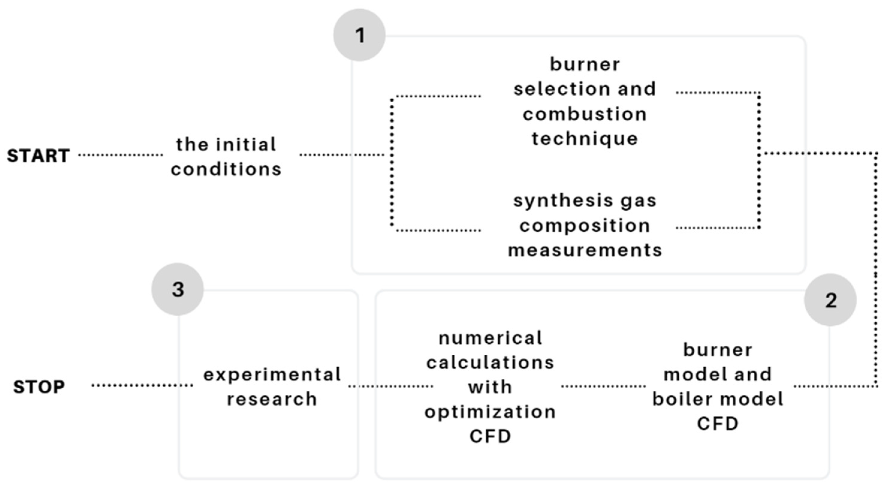
2. Materials and Methods

The paper proposes a 3-stage, semi-empirical procedure for creating a numerical model of the boiler (Figure 1). After determining the target boiler power and combustion technique in the burner, an experiment was carried out to determine the composition of the synthesis gas, which is the product of gasification processes taking place in the burner. These data were used as the boundary condition for the burner model in the cylindrical test chamber. Based on the information (combustion chamber height, temperature distribution, CO and O2 concentrations) adopted from calculations of syngas combustion in the cylindrical area (Figure 2), a numerical model of the actual boiler combustion chamber was made. Multi-variant simulations were carried out to suggest optimal chamber geometry. The last stage was the prototype of the boiler and the verification of model assumptions.

2.1. Composition and Calorific Value of the Generator Gas

In the boiler furnace, the generator gas (syngas) will be burned, which was obtained in the process of wood biomass gasification; the wood biomass was in the form of pellets with a diameter of 3 mm and a length of about 10–15 mm (average values). The fuel characteristics of the tested biomass are shown in Table 1. Samples for analytical determinations were taken in accordance with the PN-EN 14778:2011 standard Solid biofuels–Sampling. Fuel properties were determined according to PN-EN 14774-1:2010 Solid biofuels—Determination of moisture content—Drying method—Part 1: Total moisture; PN-EN 14775:2010 Solid biofuels—Determination of Ash; PN-EN 14918: 2010 Solid biofuels—Determination of calorific value; PN-EN 15104:2011 Solid biofuels—Determination of total carbon, hydrogen and nitrogen content—Instrumental methods; PN-EN 15289: 2011 Solid biofuels—Determination of total sulphur and chlorine. The gasification process was carried out in the retort burner chamber (Figure 2a) with an added cylindrical chamber (Figure 2). The gasification factor was air. During gasification, the air demand index expressed as a fuel/air ratio F/A was 0.72, and fuel consumption F = 0.000668 g/s, air gasification consumption A = 0.000927 g/s. Syngas was obtained; its composition in the dry state is presented in Table 2. The concentrations of individual components were determined using the GAS 3000 syngas analyser. The calorific value of syngas was calculated based on Formula (1) [17]:
LHV = 126[CO] + 108[H2] + 359 [CH4],
where [CO], [H2], and [CH4] percentage volumetric shares of syngas flammable components are indicated.
The method of measuring the synthesis gas composition is shown in Figure 3. In order to separate the syngas from the environment, a cylindrical syngas chamber (1) was added to the burner, to which this gas flows from the furnace (2). Gas samples were collected through the syngas analyser system (9) to measure its composition. The gasification air (primary air) was supplied by the blowing fan (7) and through the ducts arranged on the perimeter of the lower part (4). This air enters the fuel layer fed continuously to the furnace (2). Mineral residue after the gasification process automatically moves to the top of the furnace, from where periodically, after sliding up the chamber (1), is removed outside. After removing ash, the chamber (1) returns to the sealed position and in this position the syngas samples are taken through the measuring system (8) and (9). The upper air blowing ducts (secondary air) during the synthesis gas composition test are plugged. If the syngas chamber (1) for measuring the synthesis gas composition is removed under normal boiler operation conditions, then syngas combustion will take place thanks to the secondary air supplied through the cleared channels (5) around the periphery of the upper part of the furnace (Figure 2 and Figure 3).

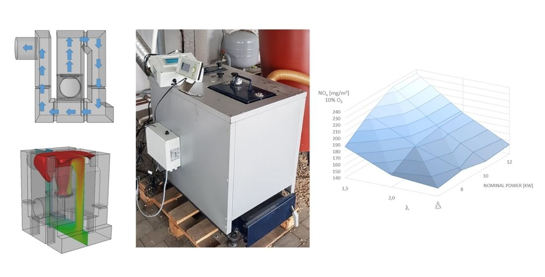
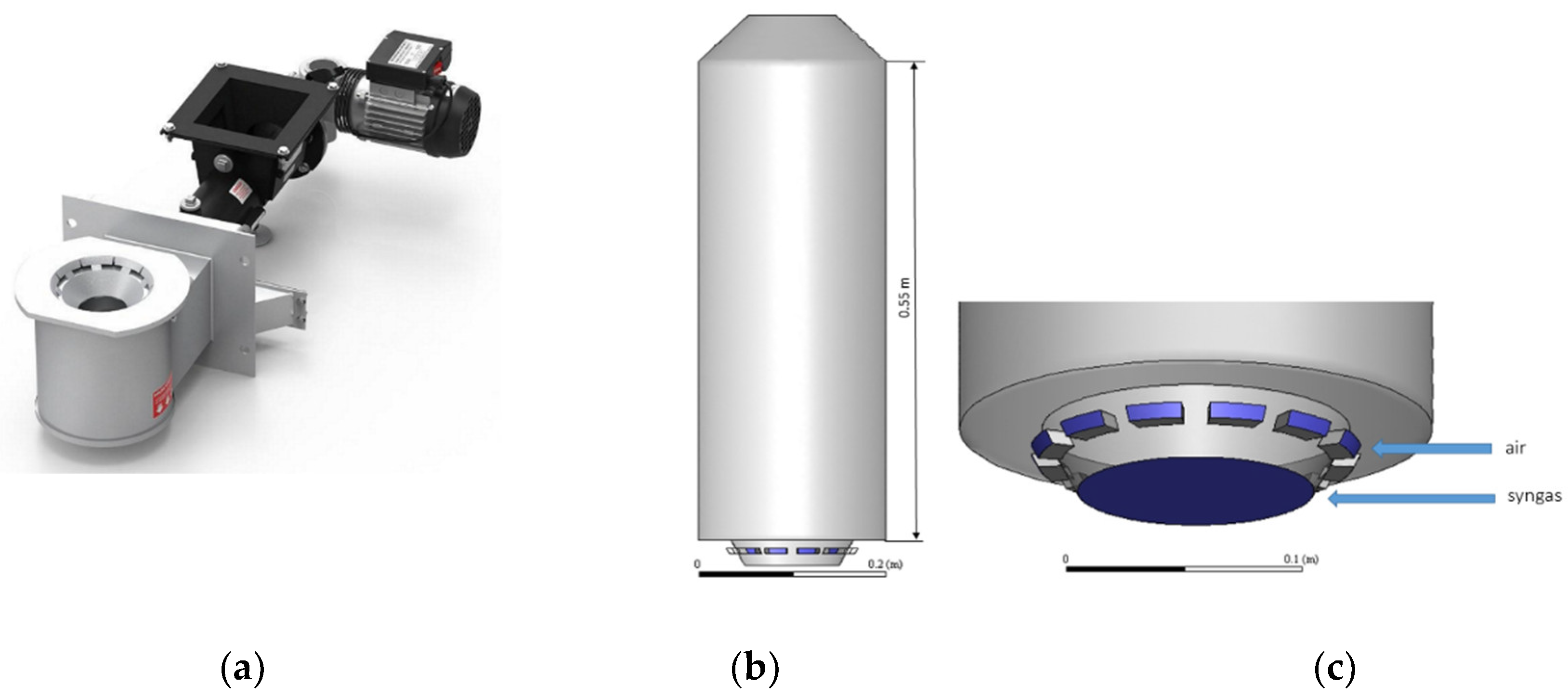
2.2. Numerical Modelling of Combustion Processes

Numerical modelling of the construction of a new boiler type began with the analysis of the combustion process in the burner (Figure 2a) of syngas produced in the process of wood pellets gasification. The composition of syngas obtained during the gasification process is provided in Table 2. In Figure 2b, a model of the burner in a cylindrical chamber is presented, which served as a starting point for determining the correct chamber geometry of the designed boiler. The essence of the numerical calculations was the following: (i) determining the height at which, at 100% burner load, all combustible particles undergo combustion in the mixture of synthesis gas and air; and, (ii) determining the temperature distribution that governs the efficiency and low-emission combustion. Numerical calculations were made assuming a syngas flow corresponding to 10 kW with an air excess factor λ = 2. The composition of syngas corresponded to the experimental (real) data given in Table 2. The air flow was calculated according to the following relationships (2) and (3):
O t   =   1 2 ( H 2   +   CO )   +   2 CH 4     O 2 [ m 3 O 2 / m 3   of fuel ]
L t   =   O t 0.21 [ m 3   of   air / m 3   of   fuel ]
In the second step of numerical modelling, a full boiler model with flue gas flow and positioning of the stake according to the original concept was made.
The numerical grid of the cylindrical combustion chamber with the burner was built of 622,000 polyhedral cells, while the numerical grid of the full boiler model consists of 945,000 polyhedral cells. In order to simulate the gas phase reactions within the full geometry of a biomass furnace in CFD, models for turbulence and radiation were selected [18]. The implementation of the realizable k-ε (enhanced wall treatment) turbulence model enables the Reynolds turbulent equations to be closed. The discrete ordinates radiation model was used to simulate the radiation heat transfer. Combustion reactions are complex and simplified into a series of global reactions with CFD modelling. The hybrid Finite-Rate/Eddy-Dissipation model [18] with the typical reactions scheme can be summarized in the form of kinetics rates [19,20]:
CH4 + 1.5O2 → CO + 2H2O Ar (s − 1) = 5.012 × 10¹¹ E’r (J/kmol) = 2.0 × 10⁸
CO + 0.5O2 → CO2 Ar (s − 1) = 2.239 × 10¹² E’r (J/kmol) = 1.7 × 10⁸
H2 + 0.5O2 → H2O Ar (s − 1) = 9.870 × 10⁸ E’r (J/kmol) = 3.1 × 10⁷
The gas phase absorption coefficients are calculated using the weighted-sum-of-grey gases model (WSGGM). Boundary conditions are as described in Table 3. Water cooling was installed on the wall in the cylindrical chamber model. The necessary settings were fixed according to the documentation for the Ansys Fluent packet. In a similar method of modelling, the operation of a biomass gasifying retort burner is presented in [21].

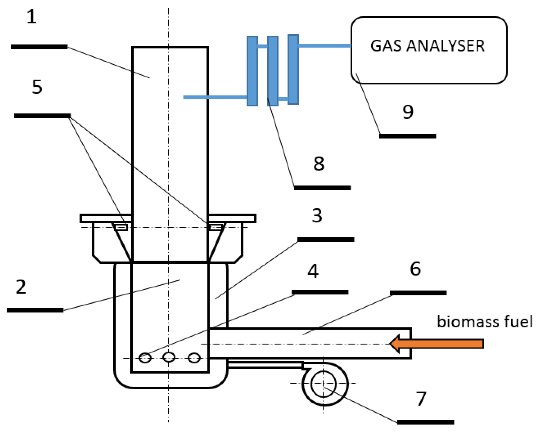
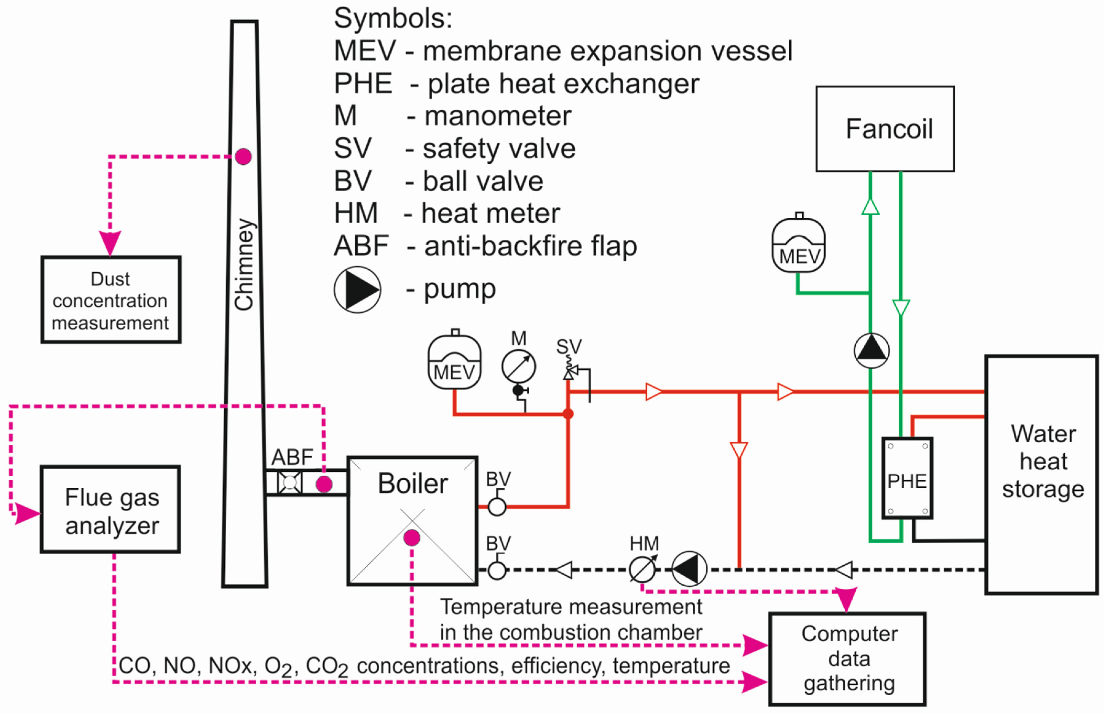
2.3. Experimental Set up and Procedure

Measurements were carried out in the boiler installation belonging to the Poznan University of Technology, Division of Heating, Air Conditioning and Air Protection. Experiments were performed in almost real-life conditions of small power boilers. Boiler installation with measurement equipment is presented in Figure 4.
Pollutant concentrations in the flue gas and flue gas temperature were measured using the Vario Plus (manufacturer—MRU GmbH Germany) flue gas analyser. CO and CxHy concentrations were measured using the infrared procedure. Oxygen (O2), nitric oxide (NO), nitrogen dioxide (NO2) concentrations were measured with electrochemical cells. The gas analyser Vario Plus also calculated the air excess ratio and chimney loss for the boiler.
Heat received by the boiler water and boiler heat output were measured with a Kamstrup heat meter. Fuel-mas was measured with Sartorius weight. The boiler heat efficiency was calculated as heat transferred to the boiler water, divided by fuel-mas, multiplied by fuel lower heating value.

3. Results and Discussions

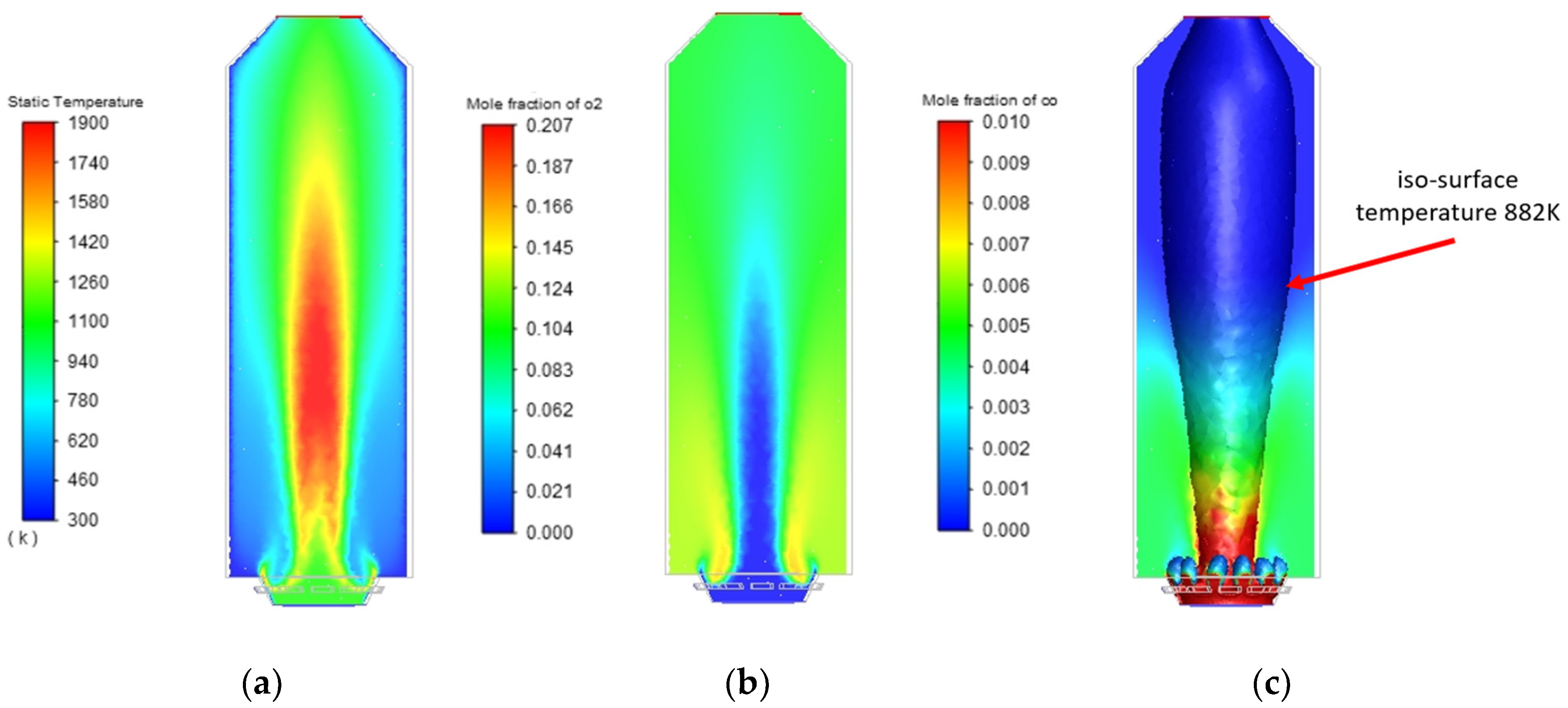
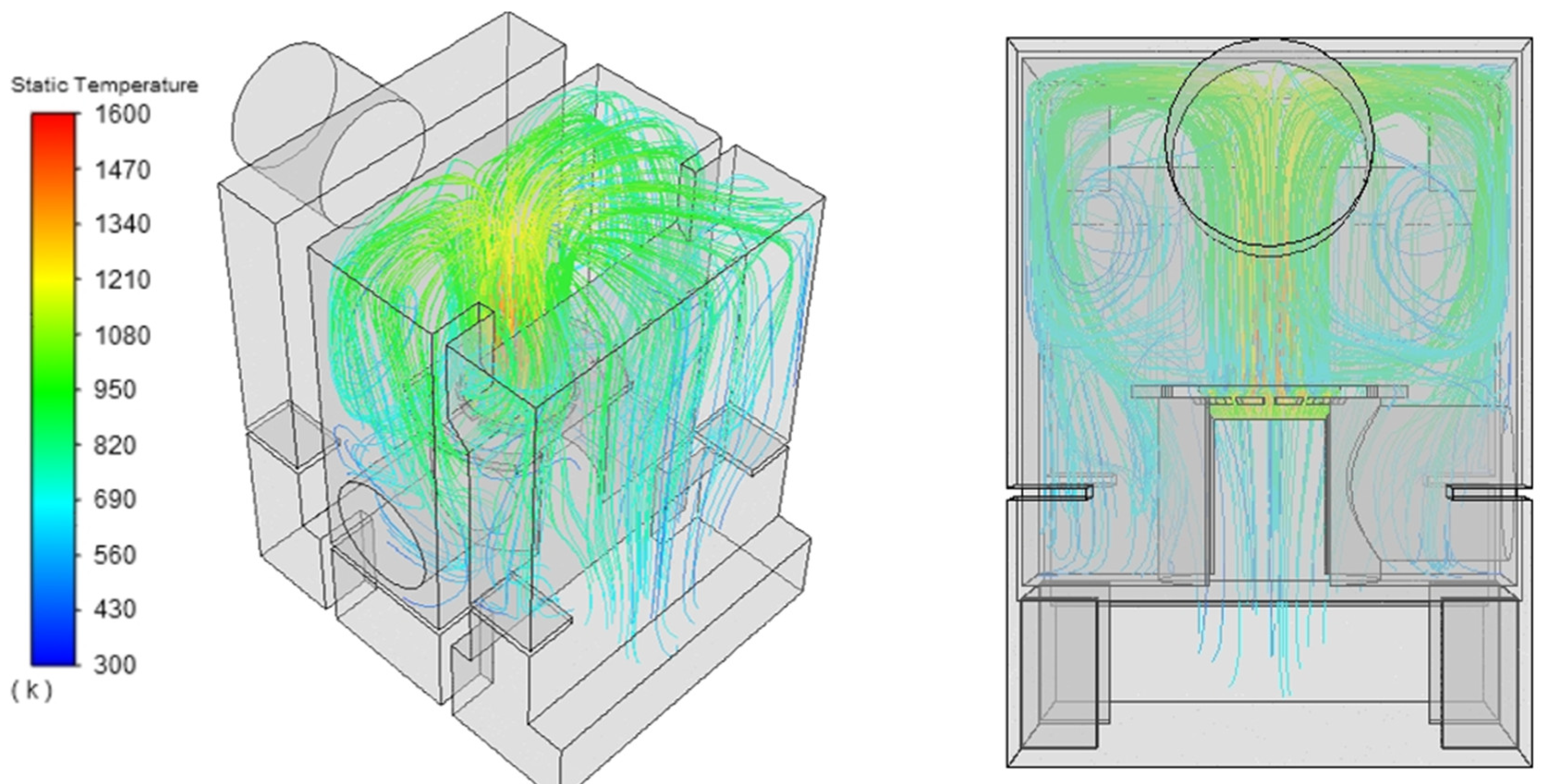
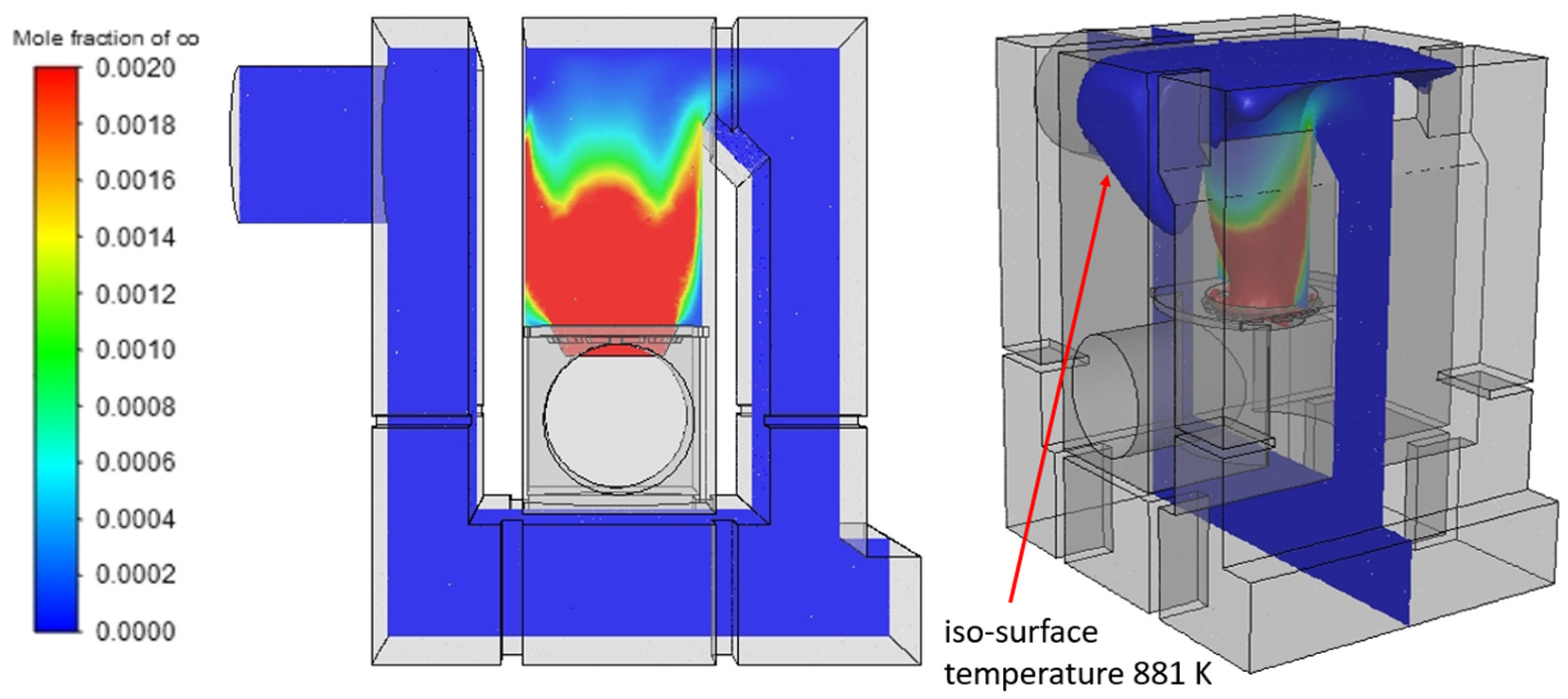
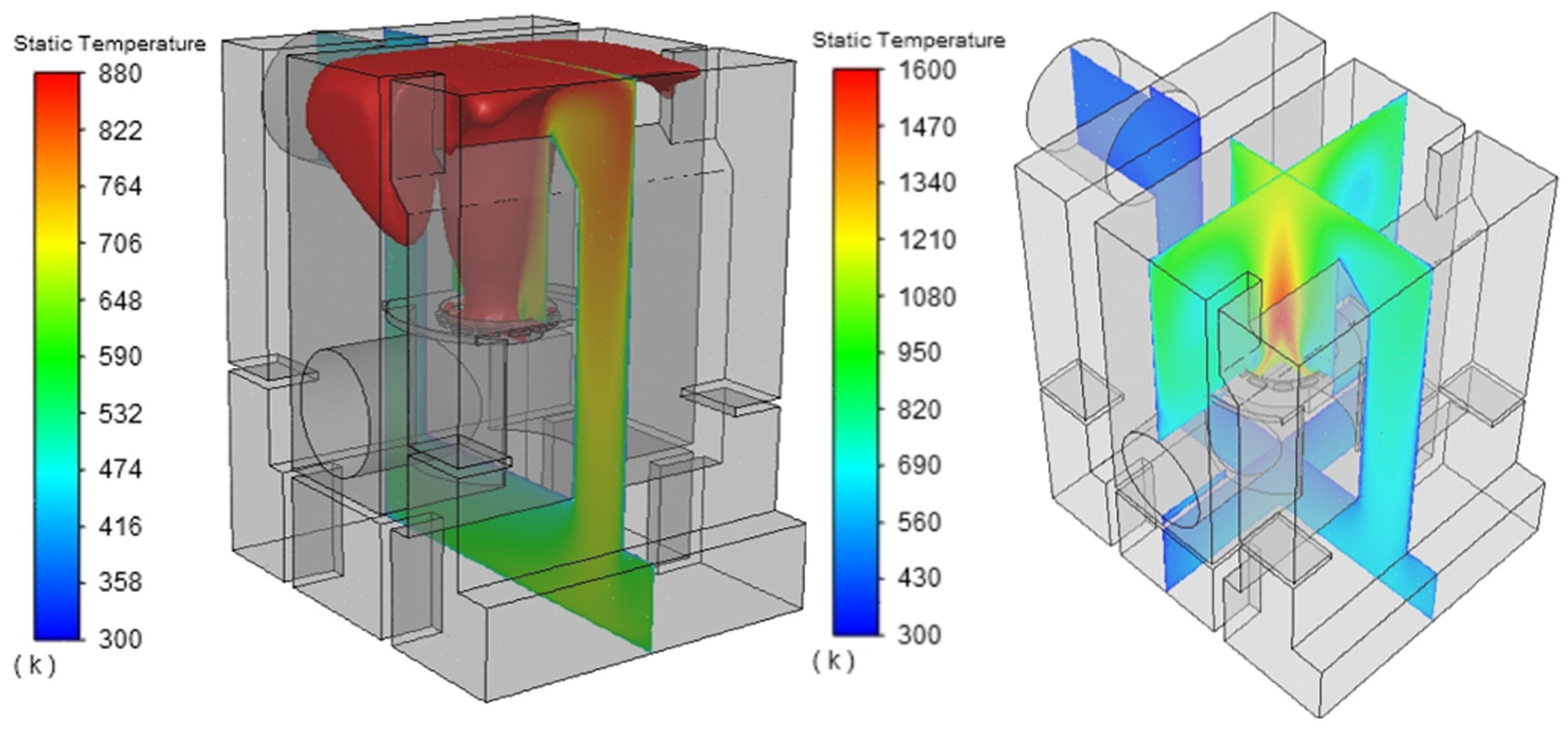
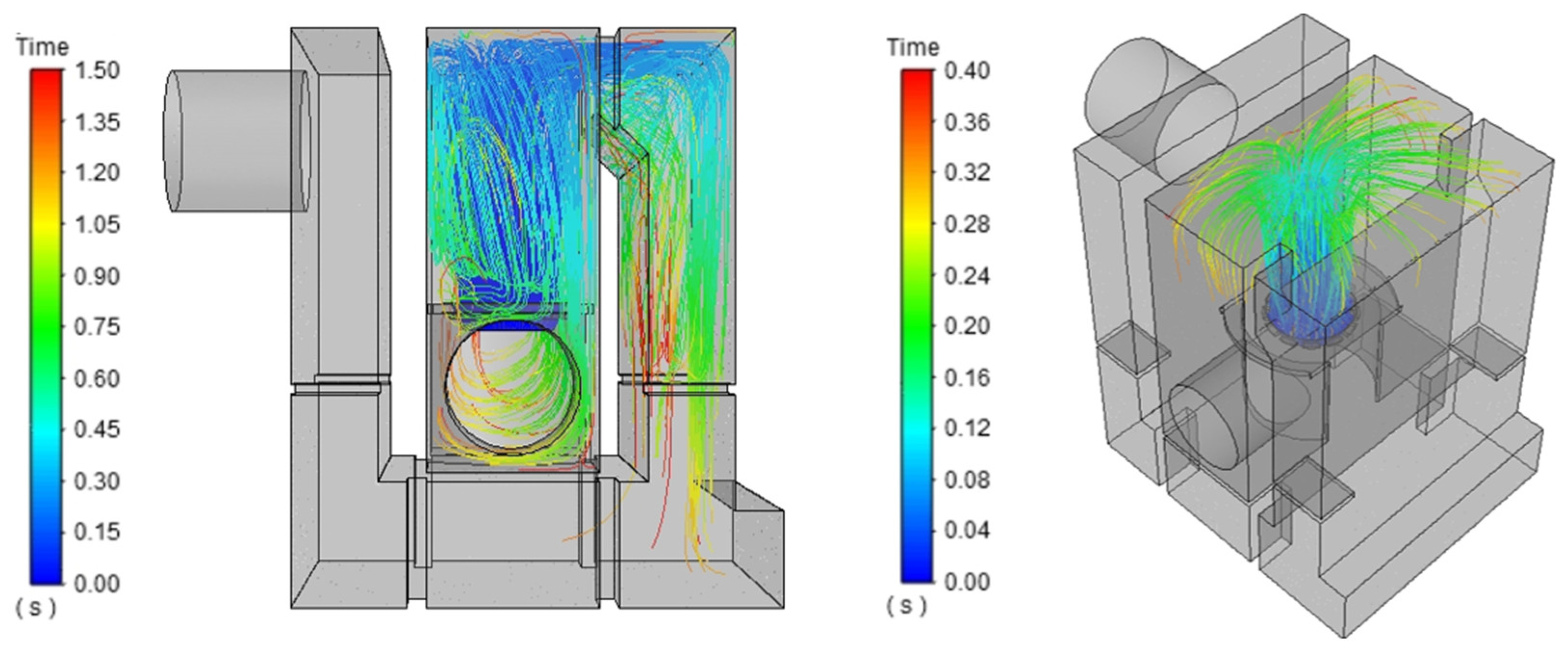
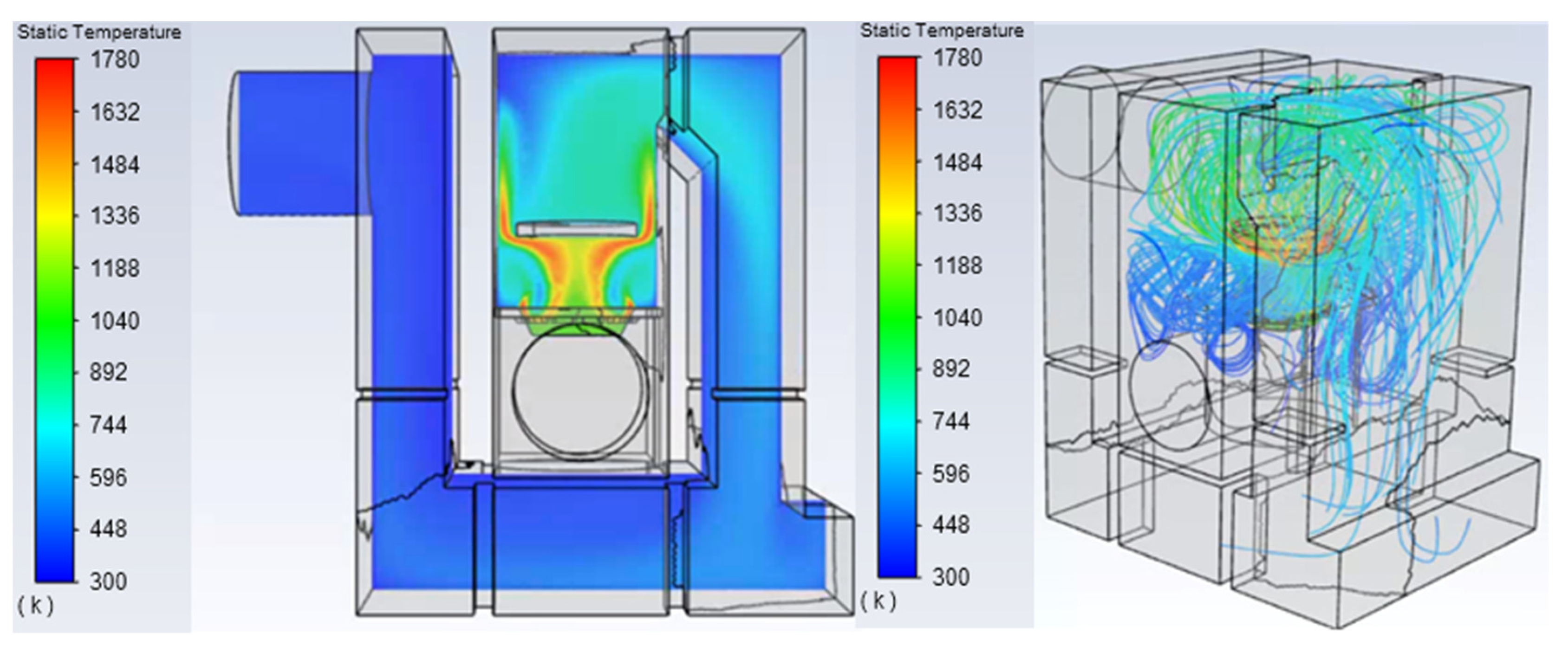
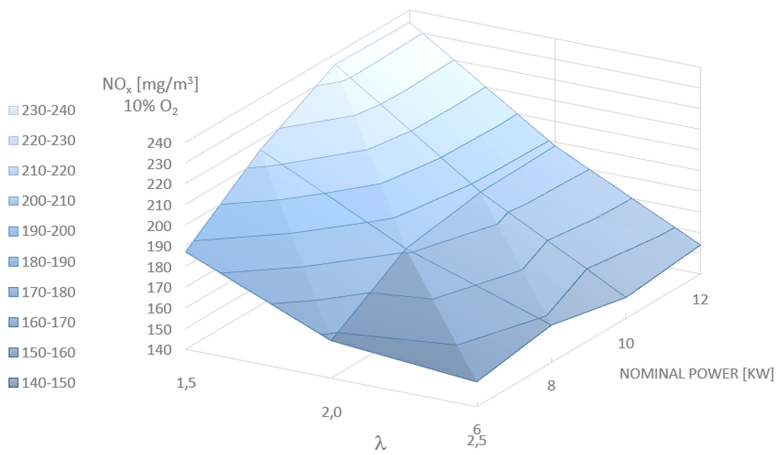
3.1. Results of Numeric Simulations

Examples of the results of temperature distribution, combustion gas products, and exhaust gas paths are given in Figure 5, Figure 6, Figure 7, Figure 8, Figure 9, Figure 10 and Figure 11. Table 4 presents the temperature and flue gas composition values in the outlet plane to the chimney from the target boiler model. Analysing the results (Figure 5c), it should be noted that only in the central part of the cylindrical chamber are there favourable conditions for the rapid burning of carbon monoxide (the temperature exceeds 882 K, i.e., the flash point of CO and other compounds, i.e., CH4 and H2). The observed CO concentration may result in the formation inside the boiler chamber, of low temperature and low O2 content zones, which are unfavourable for reducing flammable compounds. Consequently, this will lead to their emission through the chimney to the atmosphere. Based on the results of the numerical calculations of syngas combustion (syngas composition Table 2) in the burner (Figure 5), with the assumed geometry of the burner (Figure 6), the height of the combustion chamber of the boiler h = 285 mm was determined. Figure 7 shows the calculated exhaust gas path from the burner through the combustion chamber located in the central part of the boiler. It should be emphasized that, in the proposed geometry of the combustion chamber in the boiler (Figure 6 and Figure 2a), the effect of flue gas swirling was obtained (Figure 7), which promotes afterburning of carbon monoxide and also intensifies heat exchange with the water jacket. The combustion of carbon monoxide is additionally favoured by the high temperature zone, which exceeds the flash point of CO of 973 K (700 °C) in the cross section (Figure 8 and Figure 9). The upward stream of hot exhaust gases visible in Figure 7, Figure 9 and Figure 10 should therefore involve the use of a protective layer of refractory material, e.g., chamotte, etc. The geometry of the proposed combustion chamber thus ensures a long residence time (from 1 to 2 s) of gas particles in the high temperature zone (Figure 10). Figure 11 shows numerical analysis of deflector applications that is often used by boiler manufacturers. The obtained results clearly indicate that, in this way, the effect of flue gas swirling and its internal circulation is reduced, which is favourable for the low-emission nature of the boiler operation. Therefore, in the structure proposed by the authors, this classic solution should be abandoned. The risk of high temperatures affecting the top wall of the chamber can be reduced by a protective layer of refractory material.

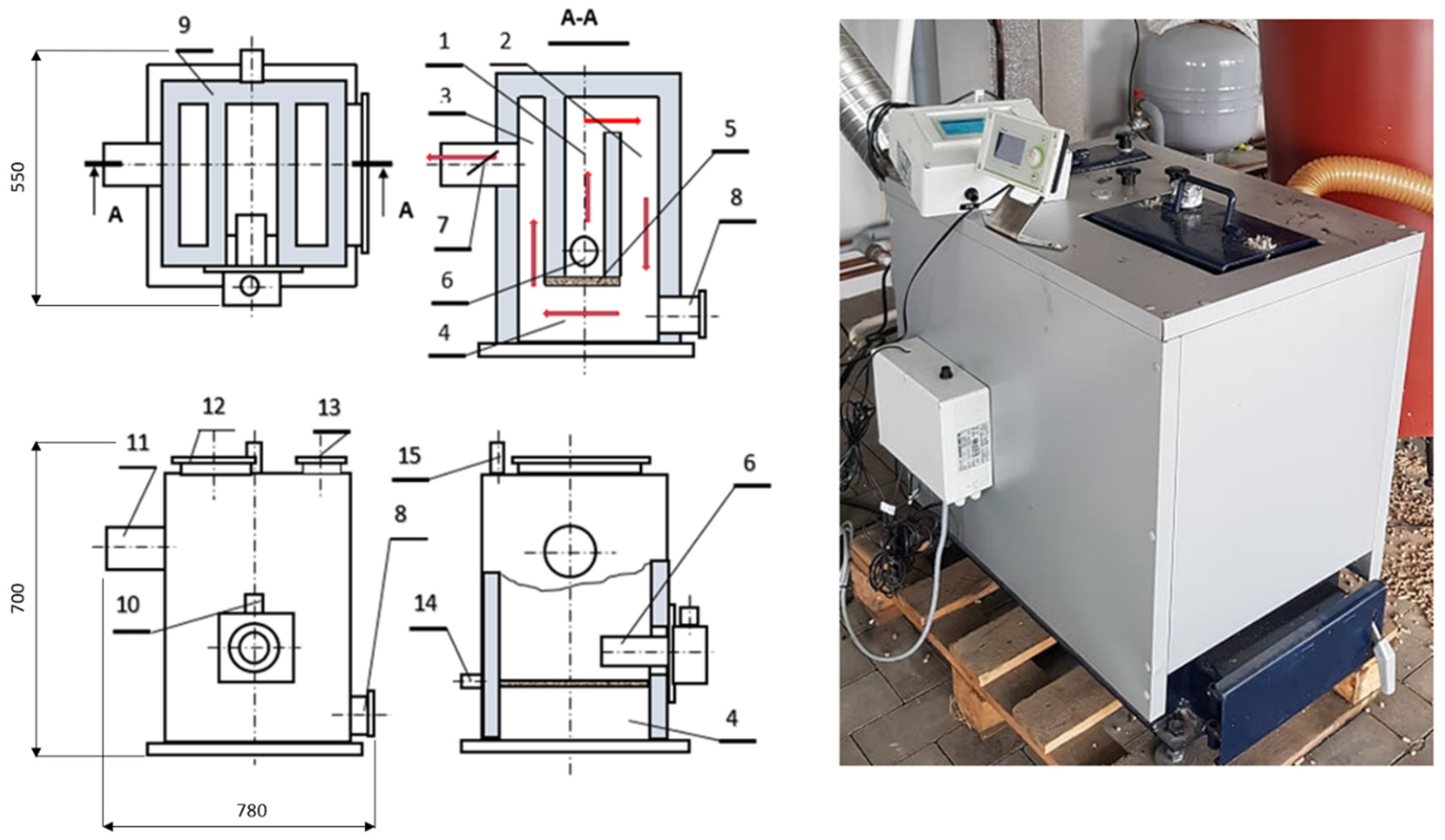
3.2. Real Model of the Boiler

Based on the results obtained from the numerical model of syngas combustion in the retort burner and the numerical model of the boiler, a prototype of a 10 kW boiler with a retort burner, a centrally located combustion chamber, and exhaust gas circulation around the combustion chamber were constructed. The real model of the boiler is shown in Figure 12. The boiler is built of the combustion chamber, where the burner (6) burning fuel in the form of wood pellets is placed at the bottom (the fuel characteristics are presented in Table 1). The furnace is fenced from below from the flue gas circulation chamber (4) and the convection chamber I (2) and the convection chamber II (3) slot parts. It is fenced off by a sliding cast iron or steel ceramic grate with heat-resistant properties (5) located under the burner (6). The grate (5) tightly closes the furnace (1) so that the fumes are not drawn downwards to the circulation chamber (4). In order to remove the ash from biomass gasification, the grate (5) is manually extended, and after removing the ash, it is moved to a tight position. The ash is poured into chamber (4), from where it is removed periodically outwards through the cleaning duct (8). Hot flue gases cool due to natural draft. They then flow from the furnace, through the convection, the flue gas circulation chamber (4) and the convection chamber II, into the smoke conduit (11) and escape to the atmosphere through the chimney. The chimney draft is regulated by a damper (7). The combustion and convection chambers are enclosed with a water jacket (9) (flue gas/water heat exchanger). The exhaust gas circulation process (which is significant) is forced by the temperature difference in the natural course of the furnace (1), convection chamber I (2), recirculation chamber (4) (exhaust gas recurrence) under the burner (6), and convection chamber II (3). Cooled flue gas is directed to the chimney via the smoke conduit (11). Fuel to the retort burner is dispensed from the tank through stub (10). Inspection hatches (12) and (13) periodically allow observation and removal of impurities that can be deposited on the heating surfaces of the furnace (1) and convection chambers (2) and (3). It should be added that, during stable boiler operation, no intrusive sediment is present on these surfaces. In addition to the exhaust gas circulation process, the central location of the combustion chamber (1) is noteworthy. This design solution enables the combustion process in chamber (1) to be carried out in adiabatic conditions with a uniformly high temperature distribution, which promotes the efficient combustion of flammable gaseous particles and soot. An expression of thermal processes occurring in the combustion chamber is the absence of tarry (black) deposits on the boiler’s heating surfaces. The flue gas/water heat exchange surface is ca. 1.2 m2, which translates into relatively small external dimensions of the boiler 10 kW − 700 × 780 × 550 mm (Figure 12).
The fuel stream was measured several times using a weighing device. Temperature in the combustion chamber was measured about 0.10 m above the flame with a radiation shielded thermocouple PtRhPt connected additionally with a temperature meter for value comparison. Heat received by the boiler water and boiler heat output were measured with an ultrasonic heat meter. All the obtained data (measured continuously) were transmitted to a personal computer via a data acquisition system. For each test run, parameter values were collected every 5 s, and averaged and mean values were calculated. This time interval of data gathering was optimal, since the measured values were not changing very quickly. Mean values for several consecutive test runs were used to obtain the overall mean value for each type of experiment. Uncertainty intervals were calculated for all measurement results with a 0.95 probability. Pellets were supplied from the hopper by means of a fixed-speed screw feeder and gravitationally fell into a small chamber. Subsequently, a horizontal fixed-speed screw pellet dispenser of each furnace introduced pellets into the burning region. Both devices were synchronized and always worked simultaneously. The fuel stream could be regulated manually by modifying operation and stand-by time of the screw pellet dispenser. The pellet furnace was equipped with its own electrically heated automatic ignition device. Air supply was provided to the furnace by a fan integrated with the furnace. The boiler lacked an automatic device with an oxygen probe (lambda sensor) that would measure oxygen concentration in the flue gas downstream the boiler. Air stream could be modified manually by fan speed regulation, ranging from 10 to 100% of its maximum value. Secondary air entered the furnace through a perforated plate located at the bottom of pellet furnace. The fan stopped operating when boiler water temperature reached its maximum value of 85 °C and reinitiated after the temperature decreased 5 °C below this maximum value.

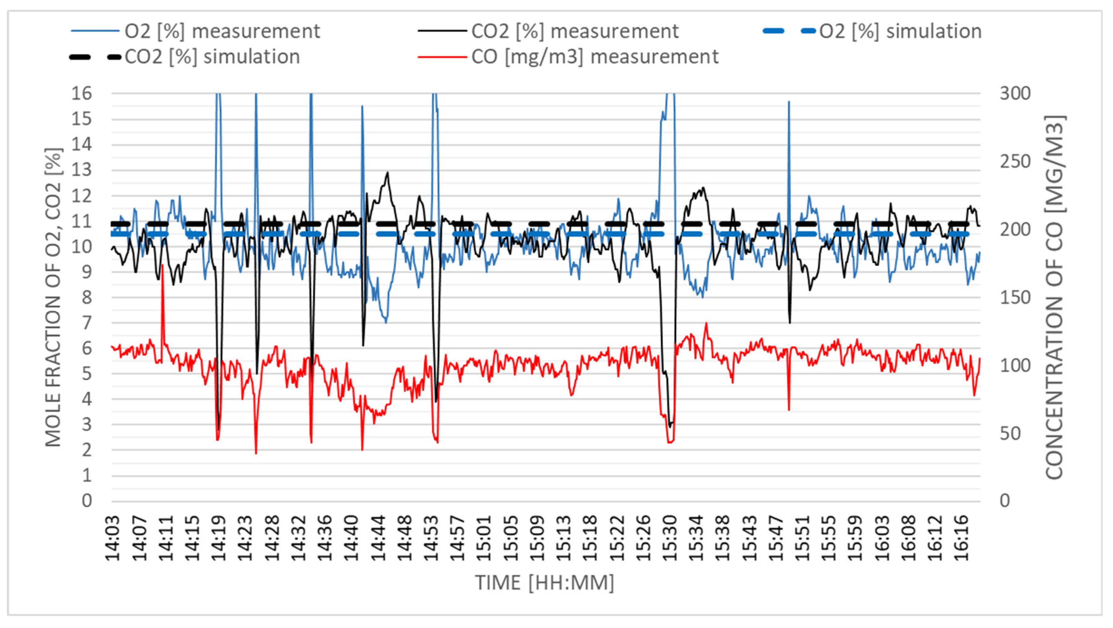
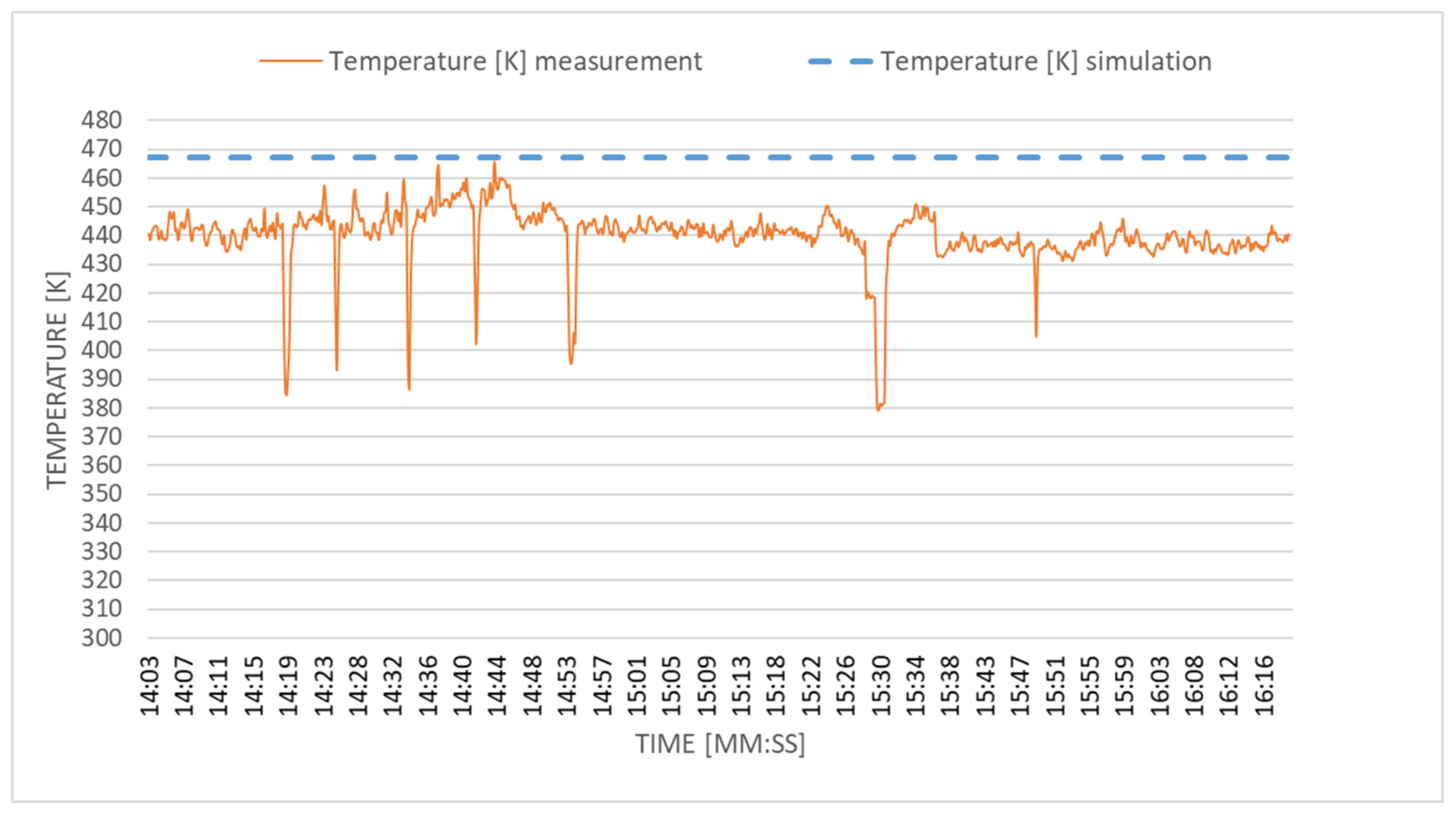
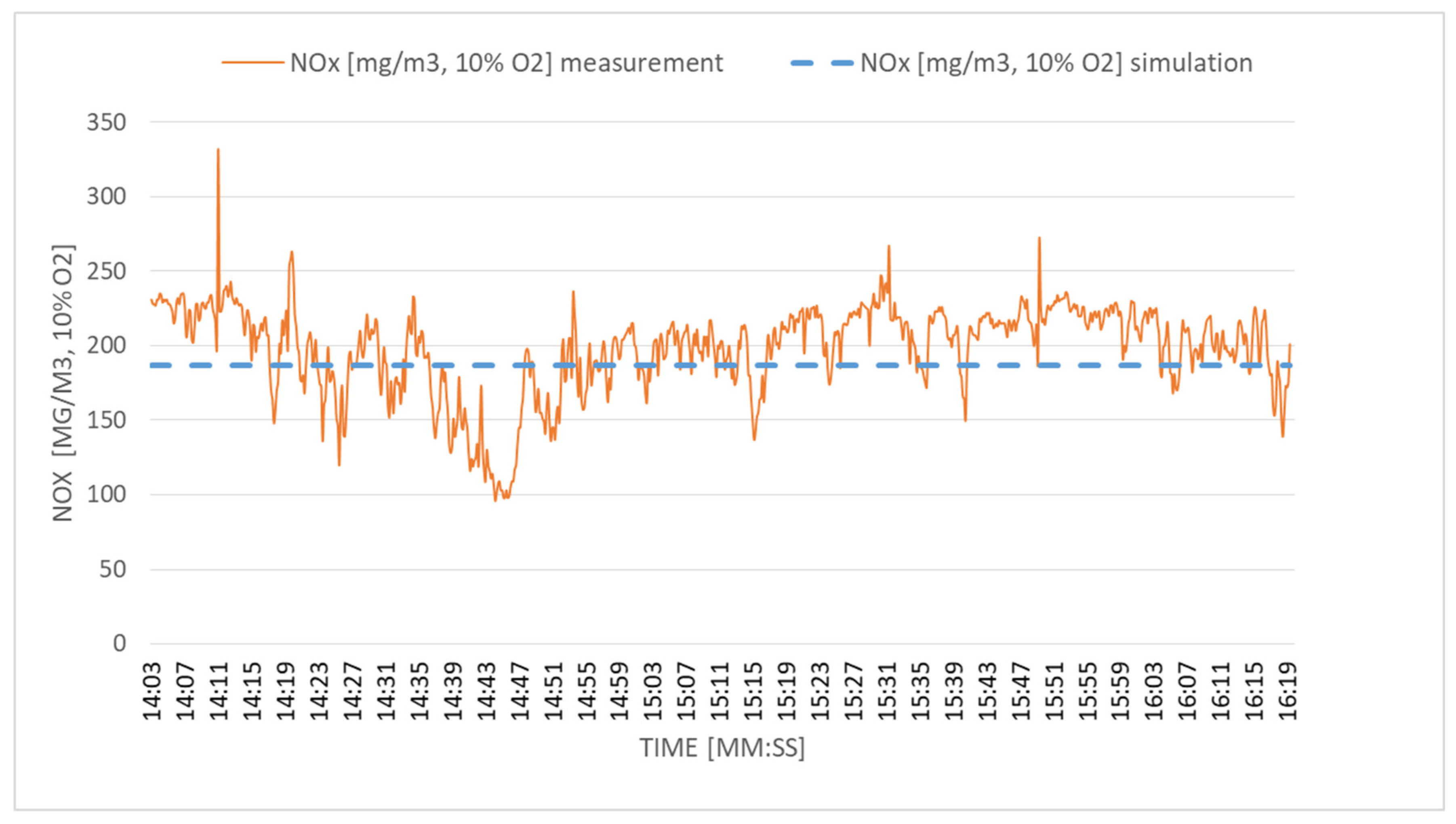
3.3. Verification of the Numerical Model in Real Conditions

In experiments carried out with the boiler, we strived to achieve a steady state in order to analyse the behaviour of the boiler. Parameters such as temperature and CO2, O2 and CO emissions were compared with those collected from numerical simulations, performed using the model (Figure 13 and Figure 14). Analysing the data of the average temperature values in the chimney and CO2, O2 emissions from a 2-h measurement and analogous values obtained from the numerical simulation, one can notice differences in the range of 2.7–7%. Experimental data show slight oscillations of the measured quantities, which is a derivative of the nature of a pellet-operated heating installation. Steady-state results are obtained from the numerical model. This is the reason for slight differences in values, but it does not affect the general nature of the simulation results obtained, based on which the research was continued. The boiler geometry adopted for numerical calculations was mapped (Figure 6), the design (executive) documentation was prepared, and the prototype presented in Figure 12 was constructed. The fuel used was wood pellets with the fuel characteristics given in Table 1. The results of the wood pellet combustion tests refer to the working boiler in optimal, determined, full load conditions, i.e., = 10 kW. Under these conditions, the boiler obtained the highest efficiency. It was, on average, η = 92.6% at the fuel calorific value LHV = 16,165 kJ/kg, with fuel consumption 0.000668 g/s and the excess air ratio was λ = 2. The efficiency estimation was based on Formula (7)
η = Q ˙ B ˙ ·   L H V
where Q ˙ —heat stream generated in the boiler (kJ/s), B ˙ —fuel stream (kg/s), LHV—calorific value of fuel (kJ/kg), η—boiler energy efficiency.
For example, in six attempts to burn wood pellets (when the percentage of oxygen and carbon dioxide in the waste gas was O2 = 10.7% and CO2 = 9.93%), the content in the carbon monoxide flue gas was on average CO = 91 mg/m3. The emission values obtained through the experiment confirmed the reliability of the previously obtained results using the numerical method presented in Figure 5 and Figure 8. The obtained emission and efficiency parameters result from the previously carried out numerical analysis of combustion in the retort burner shown in Figure 2.
The prototype of the boiler proposed in this paper is characterized (according to numerical calculations) by a simple structure with a wide possibility of modernization in the direction of the following: (i) obtaining higher energy efficiency; (ii) low NOx emissions; (iii) increasing power, e.g., to 30 kW by increasing the flue gas/water heat exchange surface with unchanged dimensions; and, (iv) increasing the efficiency of the boiler in condensing operation with the possibility of adding (in a simple way) an additional heat exchanger condensing water in the flue gas.
The temperature measurement in the chimney duct (Figure 14) indicated a value of 430 K to 470 K (157–197 °C) and the temperature measurement in the combustion chamber indicated 723 K to 773 K (450–500 °C). Both values were confirmed by numerical calculations.
Figure 13 and Figure 15 show the concentrations of the gaseous components of the flue gas CO, CO2, O2, and NOx measured in the flue (Figure 4) during the 2 h of boiler operation. The low emission of the boiler (which is related to the achievement of complete combustion conditions in it) refers to low concentrations of CO emissions, the values of which are approximately 100 mg/Nm3. Low CO emission is associated with the proposed combustion chamber system and the circular circulation of the exhaust gases in the convection channels. Such a thermal-flow system ensures swirling of exhaust gases and turbulence, which promotes the mixing of combustible compounds and oxygen under high temperature conditions. Under these conditions, the instantaneous NOx concentration values were in the range of 100–300 mg/Nm3, while the average value was 197 mg/Nm3. It was consistent with the simulation results, i.e., the value of 187 mg/Nm3. Low, similar values of NOx concentration can be obtained by the classic air and fuel staging method [22,23]. Figure 16 shows a simulation of the NOx emission depending on the excess air factor (λ) and the nominal boiler power. It should be noted that the proposed combustion technique allows one to obtain average values of NOx concentrations below 200 mg/Nm3 (converted into 10% of oxygen in the flue gas) for the nominal power of 10 kW and to ensure parameters are in line with the requirements of the ECODESIGN Directive. This is confirmed, not only by the simulation results, but also by experimental measurements. Even with a power cut of 40%, NOx emission remains stable. Increasing the excess air factor to 2.5 should enable a further reduction of NOx emissions by lowering the flame temperature and limiting the thermal mechanism of nitrogen oxide formation. It should be emphasized that, with restrictive exhaust emission standards, it seems fully justified to equip boiler installations with a responsive mechanism of reacting to instantaneous emissions by adjusting operating parameters to temporary operating conditions.

4. Conclusions

The presented research works aimed at building a prototype of a high-efficiency and low-emission heating boiler with a capacity of 10 kW included the following:
(1)
Experimental and numerical modelling of the wood pellet combustion process in a retort burner,
(2)
Numerical modelling of thermal and flow problems in the furnace and convection flue channels, and
(3)
Experimental verification of the results obtained in the numerical model.
As a result of the performed work, it was proved that the values according to the adopted numerical models turned out to be consistent with the results obtained on the test stand (where the efficiency and emission tests of the boiler prototype were carried out). The obtained results gave credibility to the innovative concept of boiler construction adopted in the numerical model. A characteristic feature of the innovative design is the centrally located irradiated combustion chamber (furnace) and the circulation of hot exhaust gases in convection channels arranged around the chamber. Such arrangement of the furnace and convection channels ensures (which has been demonstrated numerically and experimentally) quasi-adiabatic combustion at a constant temperature. In the entire volume of the combustion chamber (especially in its upper part and the first convection sequence), it ensures effective mixing of hot exhaust gases with air. This results in low concentrations in the exhaust gases (CO—91 mg/Nm3 on average, NOx—197 mg/Nm3) and is conducive to achieving high efficiency, the average value of which is 92%. The given values refer to the 10% share of O2 in the flue gas. Noteworthy is the low, allowable (according to ECODESIGN) NOx emission value. With a power cut of 40%, NOx emission remains stable. Increasing the excess air factor to 2.5 should enable a further reduction of NOx emissions by lowering the flame temperature and limiting the thermal mechanism of nitrogen oxide formation. It should be emphasized that, with restrictive emission standards, it seems fully justified to equip boiler installations with a responsive mechanism of reacting to instantaneous emissions by adjusting operating parameters to temporary operating conditions. The obtained results showed that the adopted innovative, non-standard boiler structure with a capacity of 10 kW can be successfully applied for low-emission heating of residential buildings.
The results obtained from the tests of the 10 kW boiler (prototype) indicate the possibility of further research on improving the structure, e.g.,: (i) maintaining its dimensions by increasing the heating surface in convection channels, e.g., with ribbing, placing a bundle of water pipes in the space above the combustion chamber; and, (ii) the reduction of NOx emissions by returning portion of the hot exhaust gases from e.g., the lower (horizontal) convection duct to the combustion chamber.

Author Contributions

Conceptualization, P.M., D.K. and S.P.; Formal analysis, D.K. and S.P.; Investigation, M.J.; Methodology, P.M., D.K. and S.P.; Software, P.M. All authors have read and agreed to the published version of the manuscript.

Funding

This research received no external funding.

Conflicts of Interest

The authors declare no conflict of interest.

References

  1. Olsen, Y.; Nøjgaard, J.K.; Olesen, H.R.; Brandt, J.; Sigsgaard, T.; Pryor, S.C.; Ancelet, T.; Viana, M.d.M.; Querol, X.; Hertel, O. Emissions and source allocation of carbonaceous air pollutants from wood stoves in developed countries: A review. Atmos. Pollut. Res. 2020, 11, 234–251. [Google Scholar] [CrossRef]
  2. Ding, S.; Dang, Y.G.; Li, X.M.; Wang, J.J.; Zhao, K. Forecasting Chinese CO2 emissions from fuel combustion using a novel grey multivariable model. J. Clean. Prod. 2017, 162, 1527–1538. [Google Scholar] [CrossRef]
  3. Yatkin, S.; Gerboles, M.; Belis, C.A.; Karagulian, F.; Lagler, F.; Barbiere, M.; Borowiak, A. Representativeness of an air quality monitoring station for PM2.5 and source apportionment over a small urban domain. Atmos. Pollut. Res. 2020, 11, 225–233. [Google Scholar] [CrossRef] [PubMed]
  4. Letschert, V.; Desroches, L.B.; Ke, J.; McNeil, M. Energy efficiency—How far can we raise the bar? Revealing the potential of best available technologies. Energy 2013, 59, 72–82. [Google Scholar] [CrossRef]
  5. Polverini, D. Energy efficient ventilation units: The role of the Ecodesign and Energy Labelling regulations. Energy Build. 2018, 175, 141–147. [Google Scholar] [CrossRef]
  6. EUR-Lex—32009L0125—EN—EUR-Lex. Available online: https://eur-lex.europa.eu/legal-content/EN/ALL/?uri=CELEX%3A32009L0125 (accessed on 8 October 2020).
  7. Dafnomilis, I.; Hoefnagels, R.; Pratama, Y.W.; Schott, D.L.; Lodewijks, G.; Junginger, M. Review of solid and liquid biofuel demand and supply in Northwest Europe towards 2030 – A comparison of national and regional projections. Renew. Sustain. Energy Rev. 2017, 78, 31–45. [Google Scholar] [CrossRef] [Green Version]
  8. Nakomcic-Smaragdakis, B.; Cepic, Z.; Dragutinovic, N. Analysis of solid biomass energy potential in Autonomous Province of Vojvodina. Renew. Sustain. Energy Rev. 2016, 57, 186–191. [Google Scholar] [CrossRef]
  9. Malico, I.; Nepomuceno Pereira, R.; Gonçalves, A.C.; Sousa, A.M.O. Current status and future perspectives for energy production from solid biomass in the European industry. Renew. Sustain. Energy Rev. 2019, 112, 960–977. [Google Scholar] [CrossRef]
  10. Ferreira, S.; Monteiro, E.; Brito, P.; Vilarinho, C. Biomass resources in Portugal: Current status and prospects. Renew. Sustain. Energy Rev. 2017, 78, 1221–1235. [Google Scholar] [CrossRef]
  11. Thomson, H.; Liddell, C. The suitability of wood pellet heating for domestic households: A review of literature. Renew. Sustain. Energy Rev. 2015, 42, 1362–1369. [Google Scholar] [CrossRef]
  12. Verma, V.K.; Bram, S.; Delattin, F.; De Ruyck, J. Real life performance of domestic pellet boiler technologies as a function of operational loads: A case study of Belgium. Appl. Energy 2013, 101, 357–362. [Google Scholar] [CrossRef]
  13. Büchner, D.; Schraube, C.; Carlon, E.; von Sonntag, J.; Schwarz, M.; Verma, V.K.; Ortwein, A. Survey of modern pellet boilers in Austria and Germany—System design and customer satisfaction of residential installations. Appl. Energy 2015, 160, 390–403. [Google Scholar] [CrossRef]
  14. Patiño, D.; Crespo, B.; Porteiro, J.; Míguez, J.L. Experimental analysis of fouling rates in two small-scale domestic boilers. Appl. Therm. Eng. 2016, 100, 849–860. [Google Scholar] [CrossRef]
  15. Sungur, B.; Topaloglu, B. An experimental investigation of the effect of smoke tube configuration on the performance and emission characteristics of pellet-fuelled boilers. Renew. Energy 2019, 143, 121–129. [Google Scholar] [CrossRef]
  16. Collazo, J.; Porteiro, J.; Míguez, J.L.; Granada, E.; Gómez, M.A. Numerical simulation of a small-scale biomass boiler. Energy Convers. Manag. 2012, 64, 87–96. [Google Scholar] [CrossRef]
  17. User Manual for the Synthesis Gas Analyzer GAS 3100P; G.E.I.T. EUROPE: Bunsbeek, Belgium, 2019.
  18. ANSYS® Fluent, Release 2019 R2, Help System; ANSYS, Inc.: Canonsburg, PA, USA, 2019.
  19. Chapela, S.; Porteiro, J.; Garabatos, M.; Patiño, D.; Gómez, M.A.; Míguez, J.L. CFD study of fouling phenomena in small-scale biomass boilers: Experimental validation with two different boilers. Renew. Energy 2019, 140, 552–562. [Google Scholar] [CrossRef]
  20. Gómez, M.A.; Martín, R.; Chapela, S.; Porteiro, J. Steady CFD combustion modeling for biomass boilers: An application to the study of the exhaust gas recirculation performance. Energy Convers. Manag. 2019, 179, 91–103. [Google Scholar] [CrossRef]
  21. Drosatos, P.; Nesiadis, A.; Nikolopoulos, N.; Margaritis, N.; Grammelis, P.; Kakaras, E. CFD Simulation of Domestic Gasification Boiler. J. Energy Eng. 2017, 143, 04016052. [Google Scholar] [CrossRef]
  22. Liu, H.; Chaney, J.; Li, J.; Sun, C. Control of NOx emissions of a domestic/small-scale biomass pellet boiler by air staging. Fuel 2013, 103, 792–798. [Google Scholar] [CrossRef]
  23. Chaney, J.; Liu, H.; Li, J. An overview of CFD modelling of small-scale fixed-bed biomass pellet boilers with preliminary results from a simplified approach. Energy Convers. Manag. 2012, 63, 149–156. [Google Scholar] [CrossRef]
Figure 1. Scheme of 3-stage, semi-empirical modelling of the boiler.
Energies 13 05837 g001
Figure 2. Retort burner for gasification of pellets: (a) view of the burner structure, (b) burner model in a cylindrical chamber, (c) burner model.
Energies 13 05837 g002
Figure 3. Gasification of biomass fuel in the retort burner: (1)—syngas chamber, (2)—gasification furnace, (3)—air chamber, (4)—gasification air inlets, (5)—combustion air inlets, (6)—screw feeder, (7)—air blower, (8)—syngas purification battery, (9) measurement of syngas composition—GAS 3000 syngas analyser.
Energies 13 05837 g003
Figure 4. Boiler installation with measurement equipment.
Energies 13 05837 g004
Figure 5. (a) Temperature distribution (K); (b) O2 (mole fraction); (c) CO (mole fraction) for the 1st phase of numeric modelling.
Energies 13 05837 g005
Figure 6. Geometry of furnace modelling.
Energies 13 05837 g006
Figure 7. Gas particle paths—temperature scale (K).
Energies 13 05837 g007
Figure 8. CO concentration (mole fraction).
Energies 13 05837 g008
Figure 9. Temperature distribution (K) with determined temperature zone of above 880 K.
Energies 13 05837 g009
Figure 10. Tracks of gas particles escaping from the burner—time scale (s).
Energies 13 05837 g010
Figure 11. Temperature distribution (K) and gas paths in the boiler model with deflector.
Energies 13 05837 g011
Figure 12. View of the boiler with 10 kW flue gas circulation: 1—combustion chamber, 2—convection chamber I, 3—convection chamber II, 4—combustion gas circulation chamber, 5—airtight sliding grate closing the combustion chamber, 6–10 kW retort burner, 7—thrust adjustment slide, 8—ash removal cleaning duct, 9—water jacket (flue gas/water heat exchanger), 10—fuel feed (pellet), 11—flue (exhaust outlet), 12—inspection hatch of the furnace and convection chamber II, 13—inspection hatch for convection chamber II, 14—return water connector, and 15—feed water connector.
Energies 13 05837 g012
Figure 13. Measured values of gaseous combustion products emission CO, CO2, and O2.
Energies 13 05837 g013
Figure 14. The measured value of the flue gas temperature in the chimney duct.
Energies 13 05837 g014
Figure 15. Emissions of nitrogen oxides NOx measured in the chimney.
Energies 13 05837 g015
Figure 16. Numerical simulation of the combined effect of nominal power and λ on NOx concentration in the flue gases.
Energies 13 05837 g016
Table 1. Fuel properties of wood pellets.
FuelC [%] **H [%] **S [%] **Cl [%] **N [%] **O [%] **Flammable Fraction *A [%] *Moisture Content [%]LHV kJ/kg *LHV kJ/kg
Wood pellets48.936.480.020.010.9343.5499.40.69.018,14516,165
* Expressed on a dry free basis, ** Expressed on a dry ash free basis.
Table 2. Syngas components from biomass.
ComponentUnitValue
CO2%15.1
CO%18.4
H2%14.2
CH4%3.3
N2%49.0
LHVkJ/Nm34857
Table 3. Boiler’s full-load data (N—standard temperature and pressure: 20°C, 1013 hPa).
NameParameterUnitValue
Wall–heat exchanger (walls cooled by water)Convection coefficientW/m2K2500
Water temperatureK338
Steel thicknessmm5
InletsQ of syngasNm3/s0.002059
Q of airNm3/s0.004314
Syngas temperatureK1123
Air temperatureK300
OutletVacuumPa−15
Table 4. Conditions in the chimney flue.
ParameterUnitValue
TemperatureK467
CH4% of mole fraction0.0
CO% of mole fraction0.01
O2% of mole fraction10.5
H20% of mole fraction1.6
CO2% of mole fraction10.9
Publisher’s Note: MDPI stays neutral with regard to jurisdictional claims in published maps and institutional affiliations.

