Simulations and Tests of a KRET Aerospace Penetrator


 , ,
, ,
Abstract
:1. Introduction
- Soil mechanics analysis;
- Chemical and mineralogical analysis;
- Thermal tests (e.g., measurement of the temperature under the body surface, thermal conductivity);
- Electrical and magnetic research;
- Soil sampling for further analysis or delivery on a return mission to Earth;
- Transporting and placing other components in a given soil;
- Anchoring objects.
- The ability to work in a very large temperature range (depending on the mission, the minimum temperature can reach −160 °C);
- A low weight of the device;
- Restrictions on power access;
- A long flight time (up to 12 years depending on the mission);
- Resistance to overload at startup;
- The ability to operate in a vacuum.
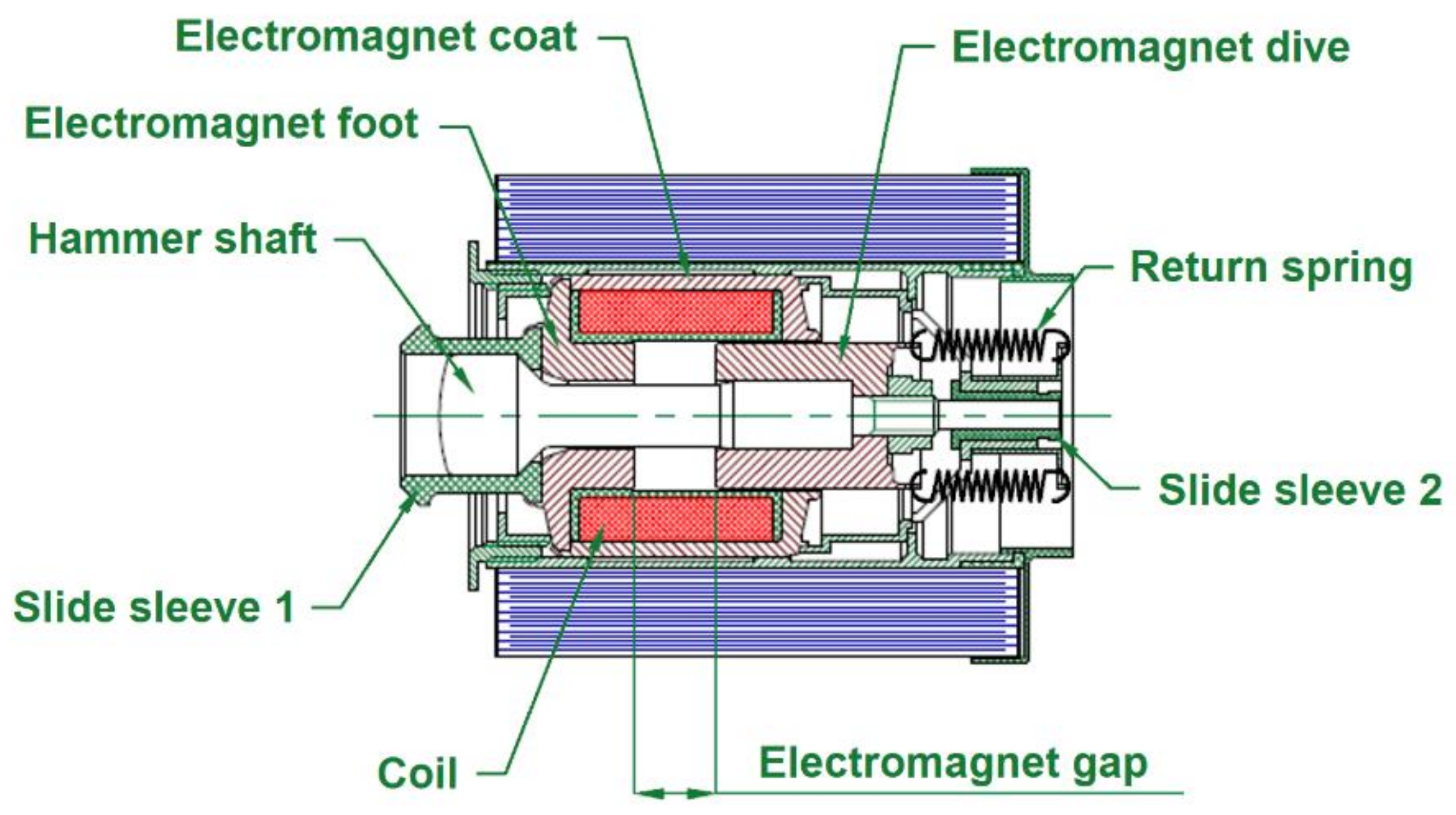
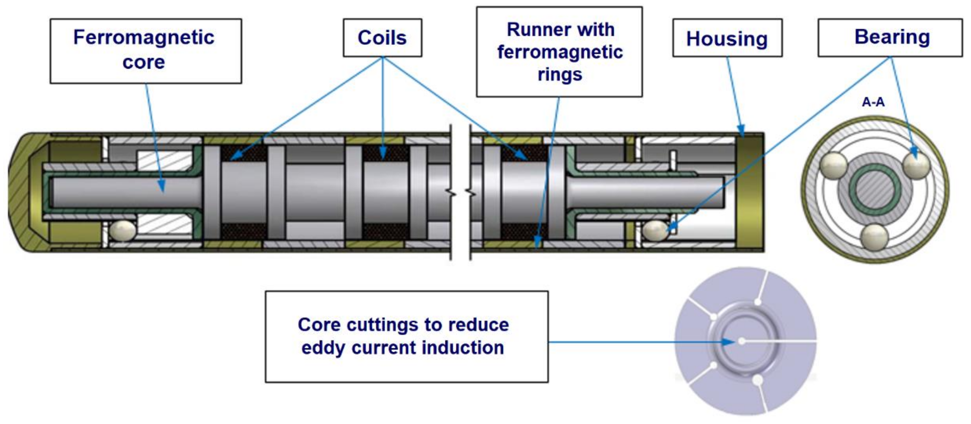
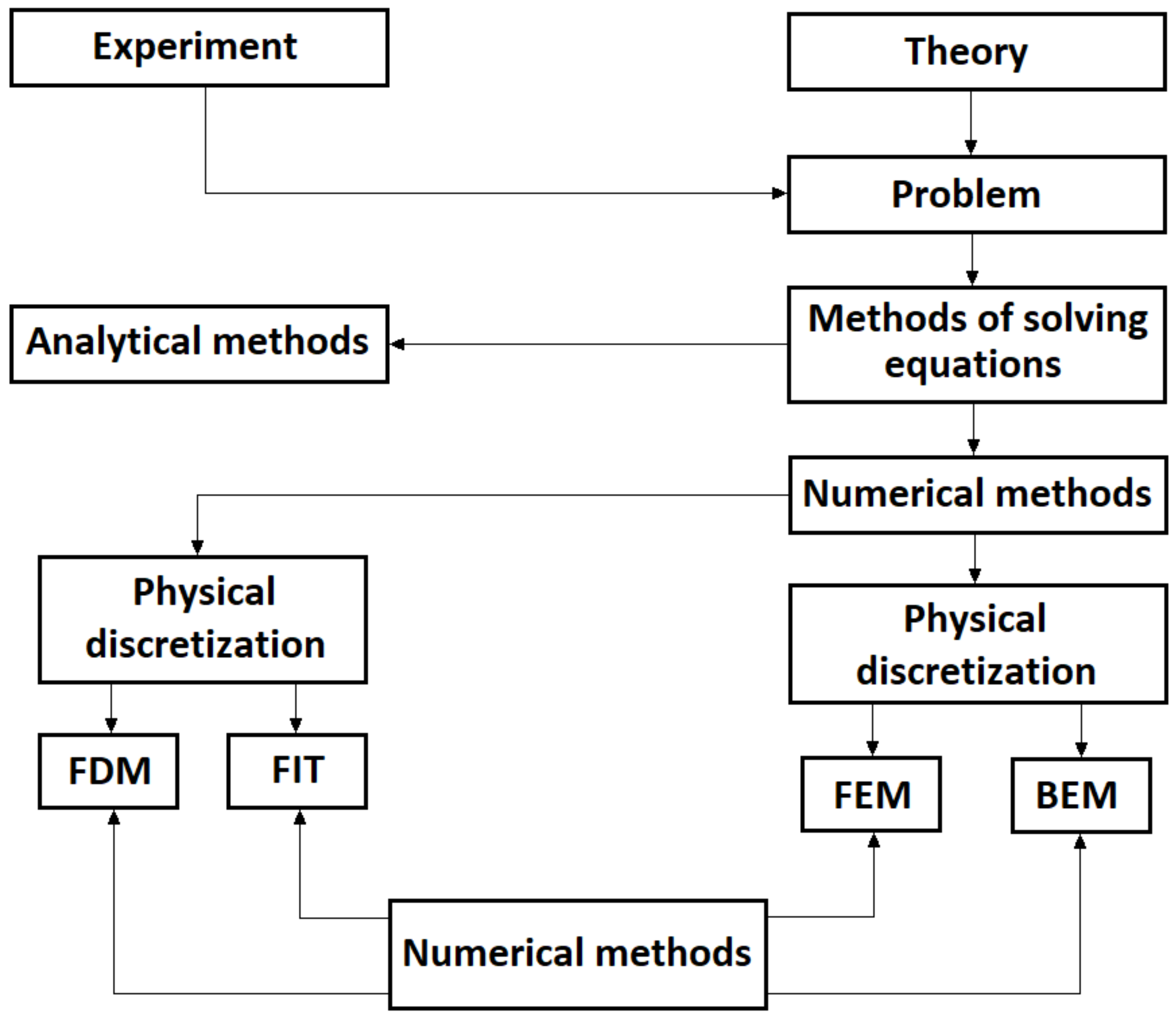
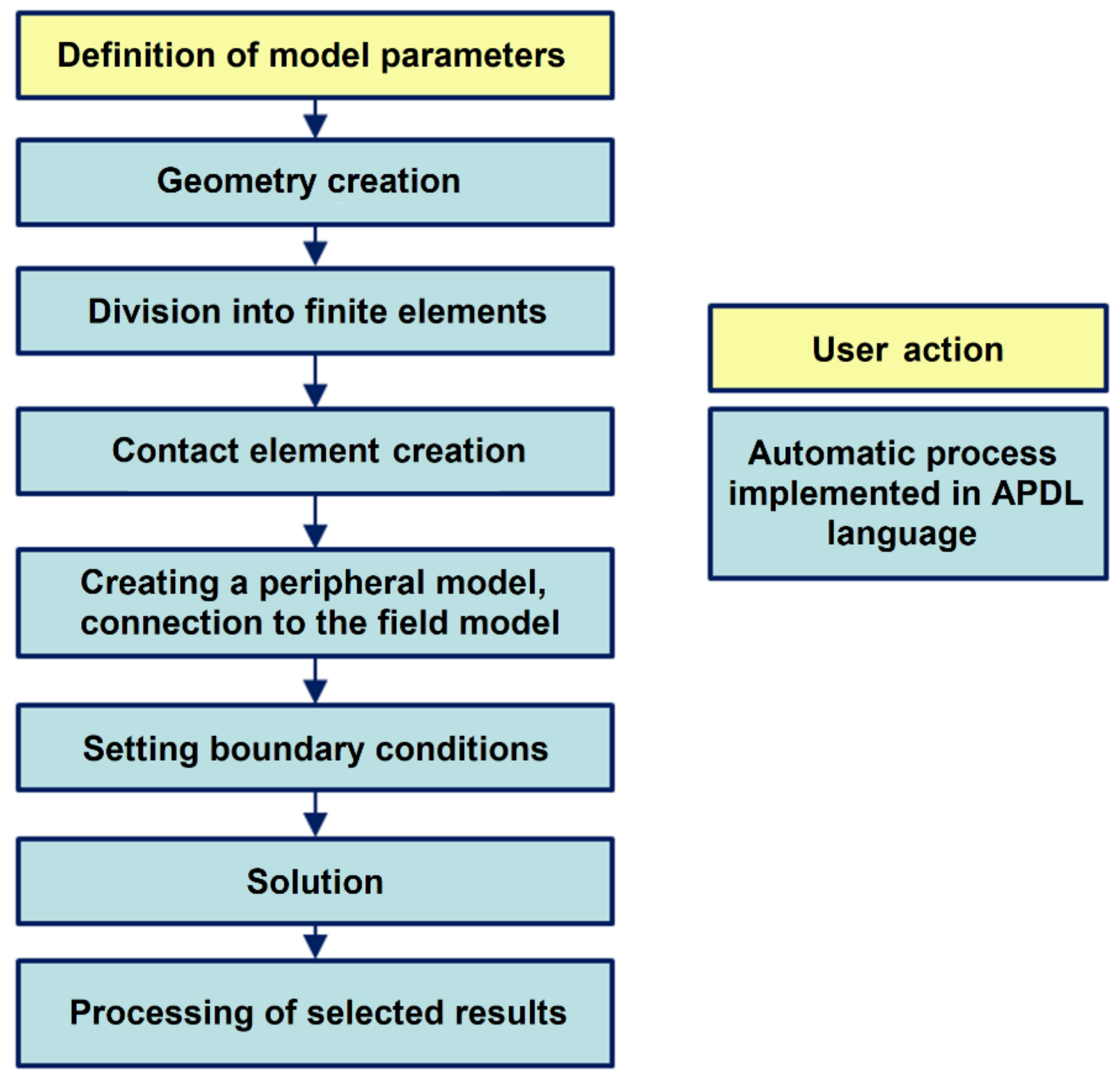
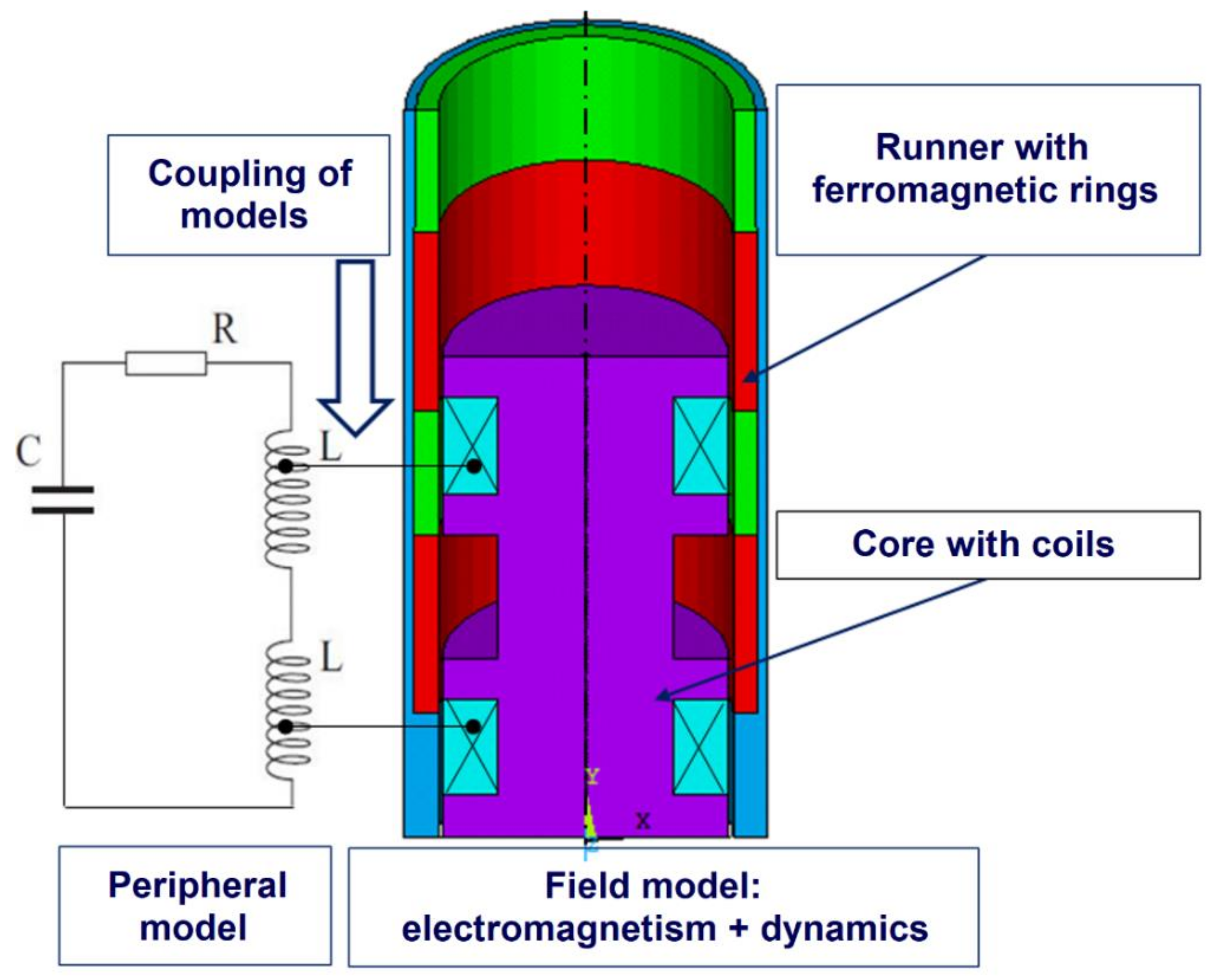
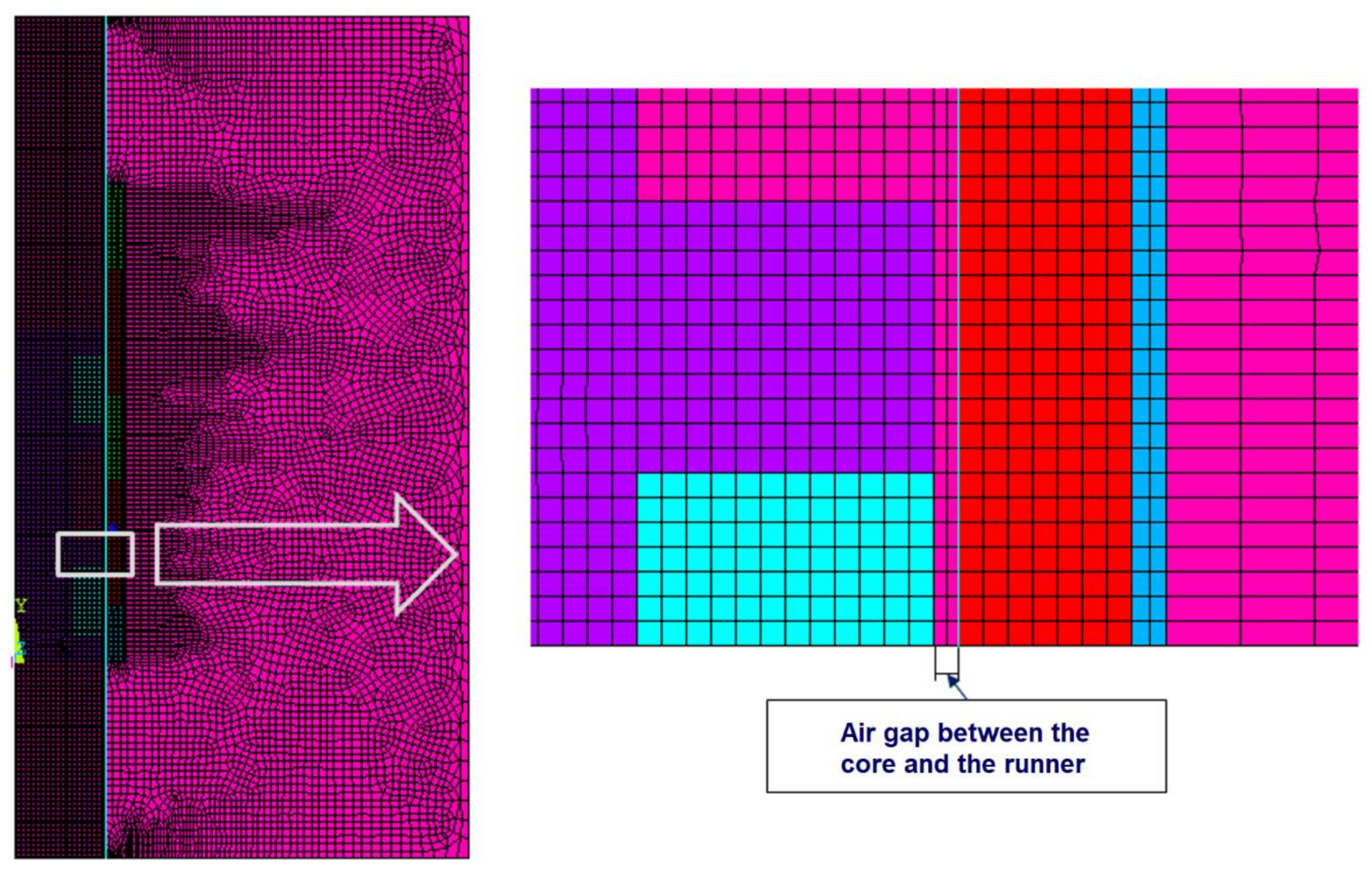
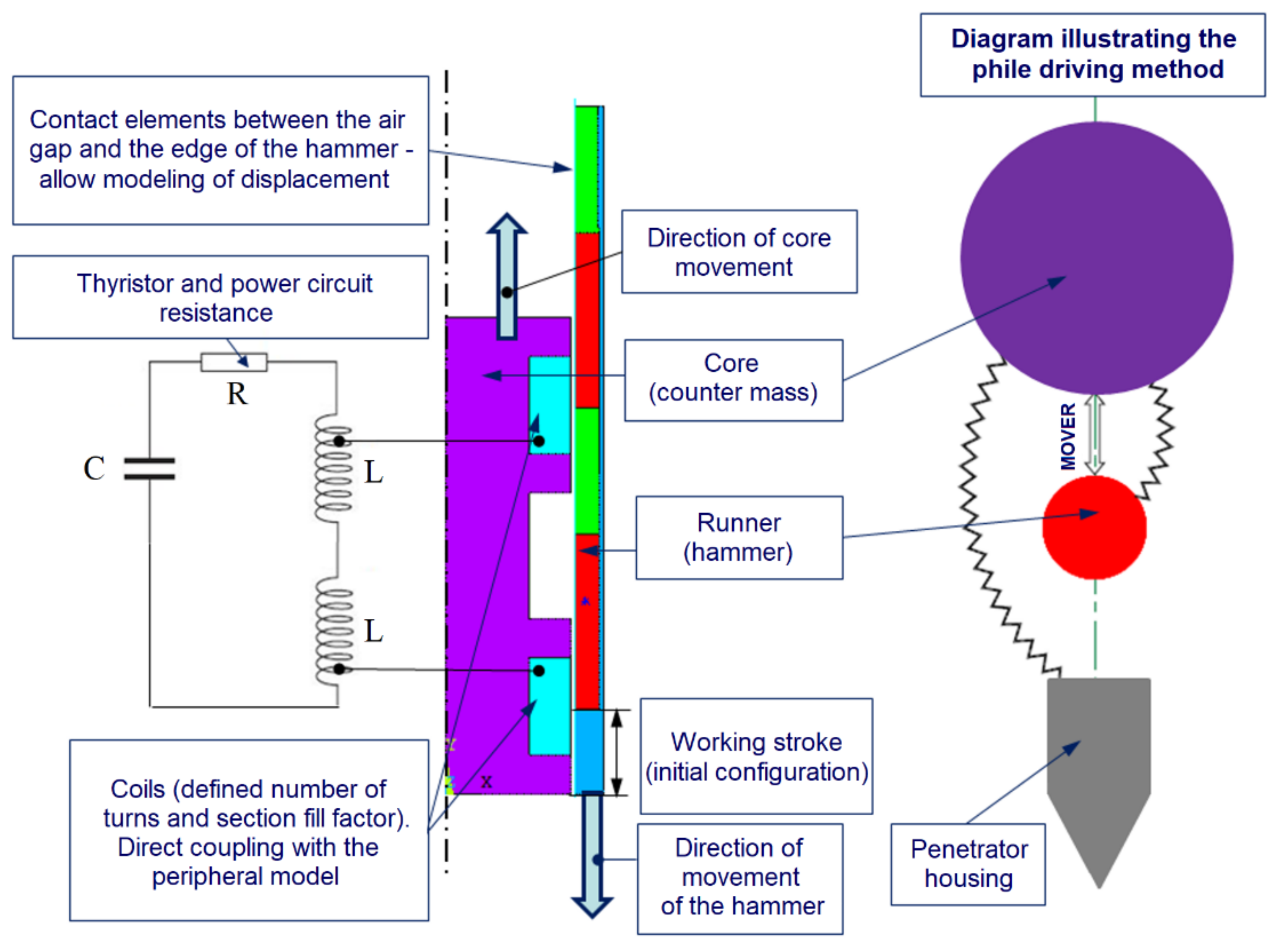
2. Numerical Model of the Tube Reluctance Actuator for Multiphysics Purposes
- Analyzing several different physical phenomena in one model (so-called Multiphysics analyses). With this option, it is possible to directly analyze the interaction between individual phenomena.
- The APDL script language—it allows the creation of parametric models simplifying the modification of the model significantly. This is a particularly important advantage, taking into account the need to analyze the impact of many different construction parameters, which entails the need to modify the model multiple times.
3. Limitations of the Numerical Model
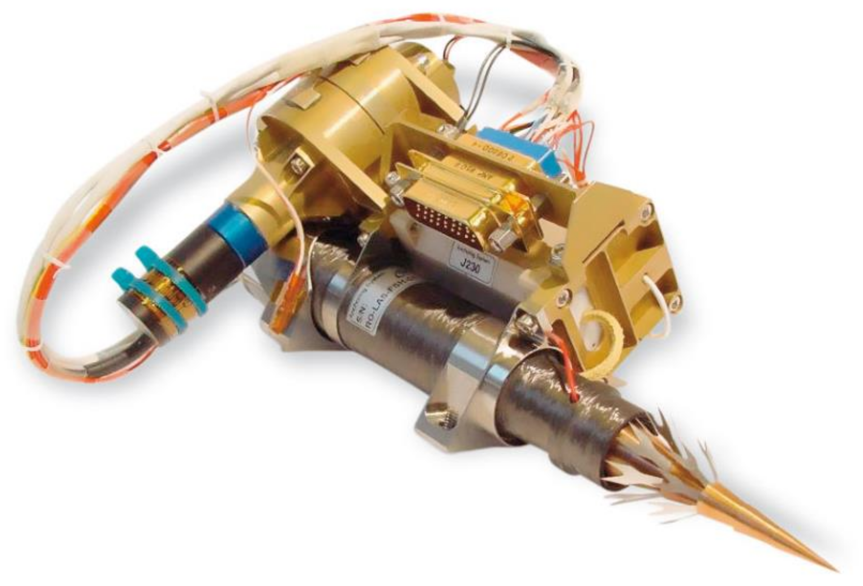
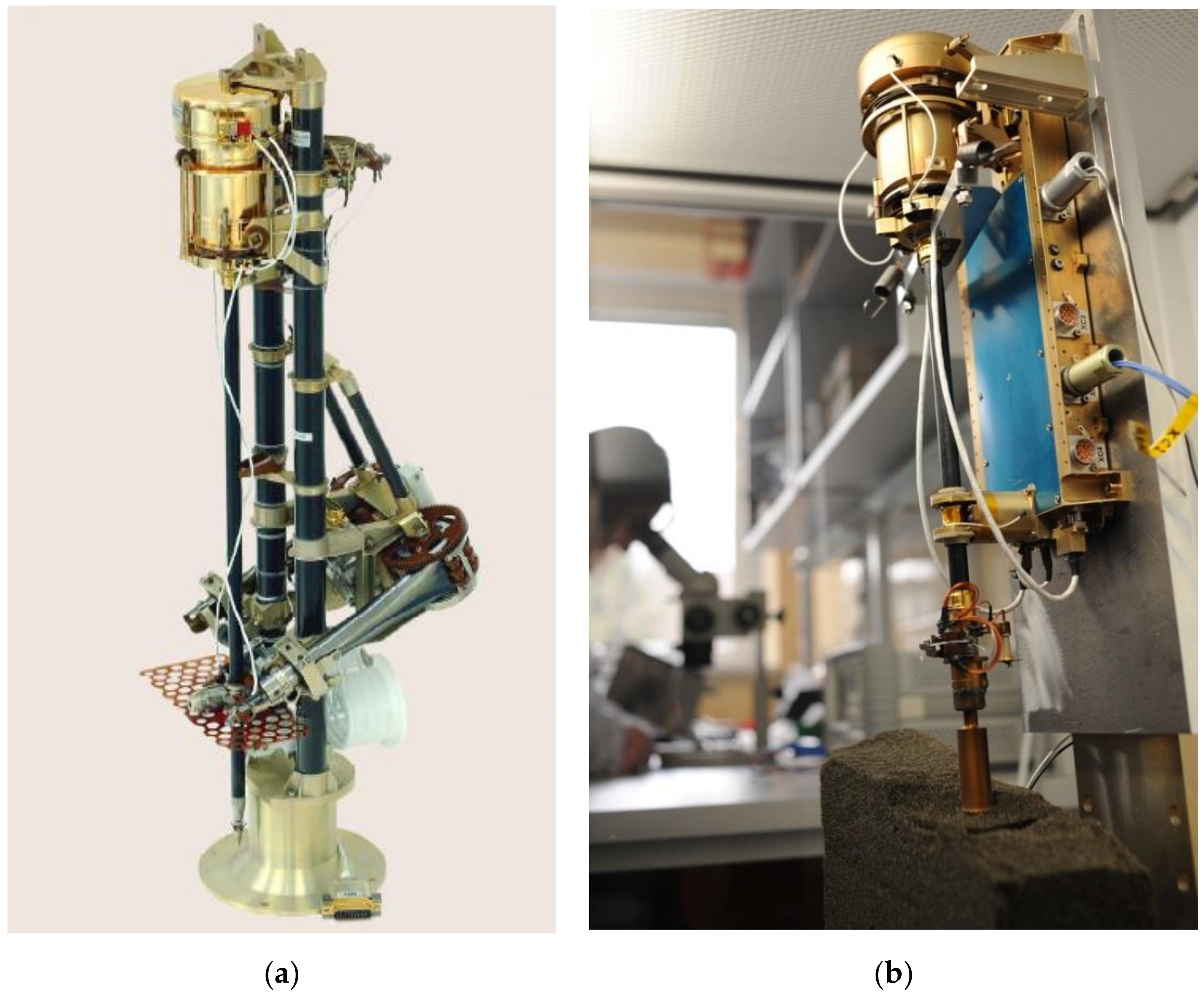
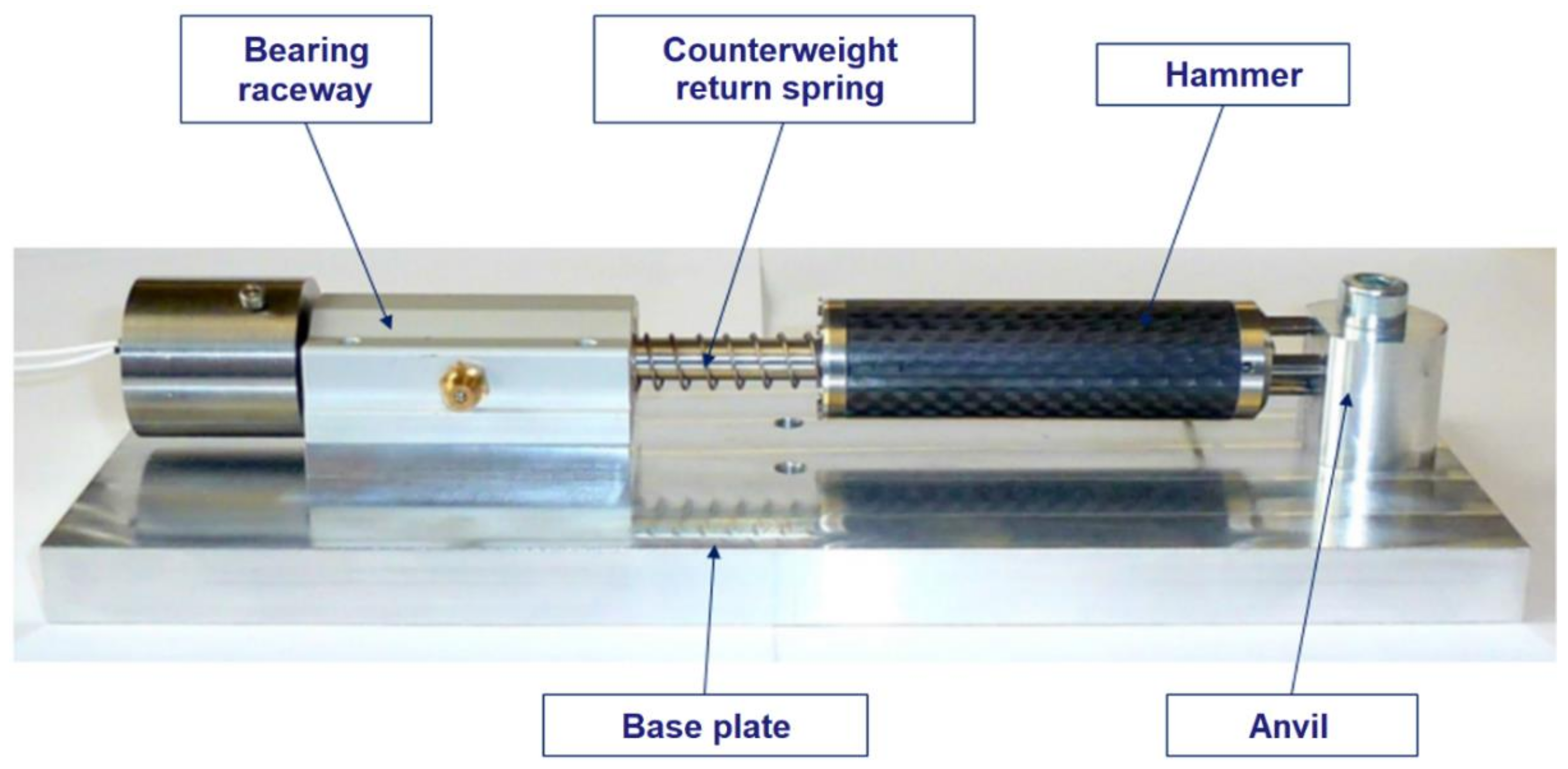
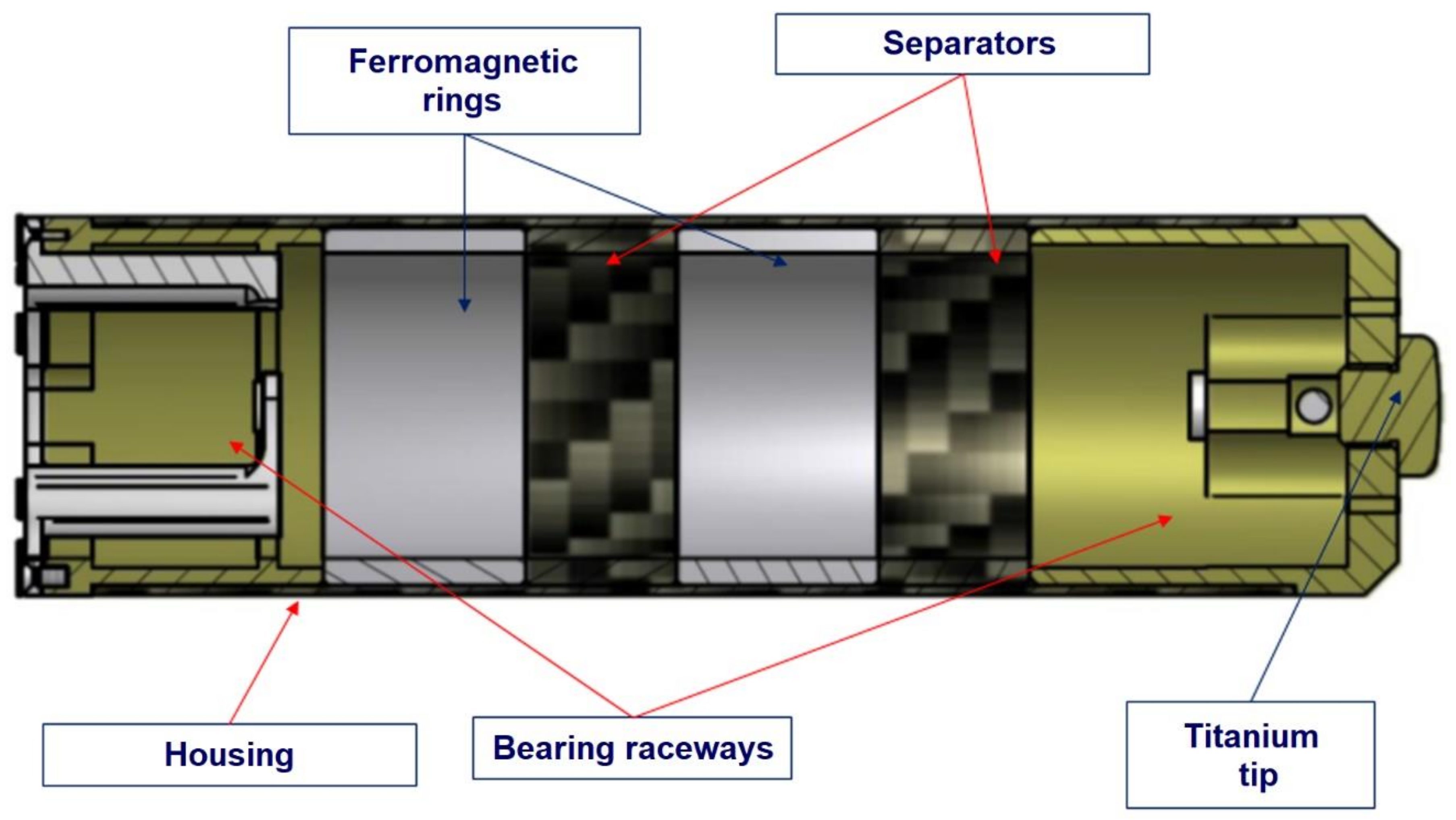
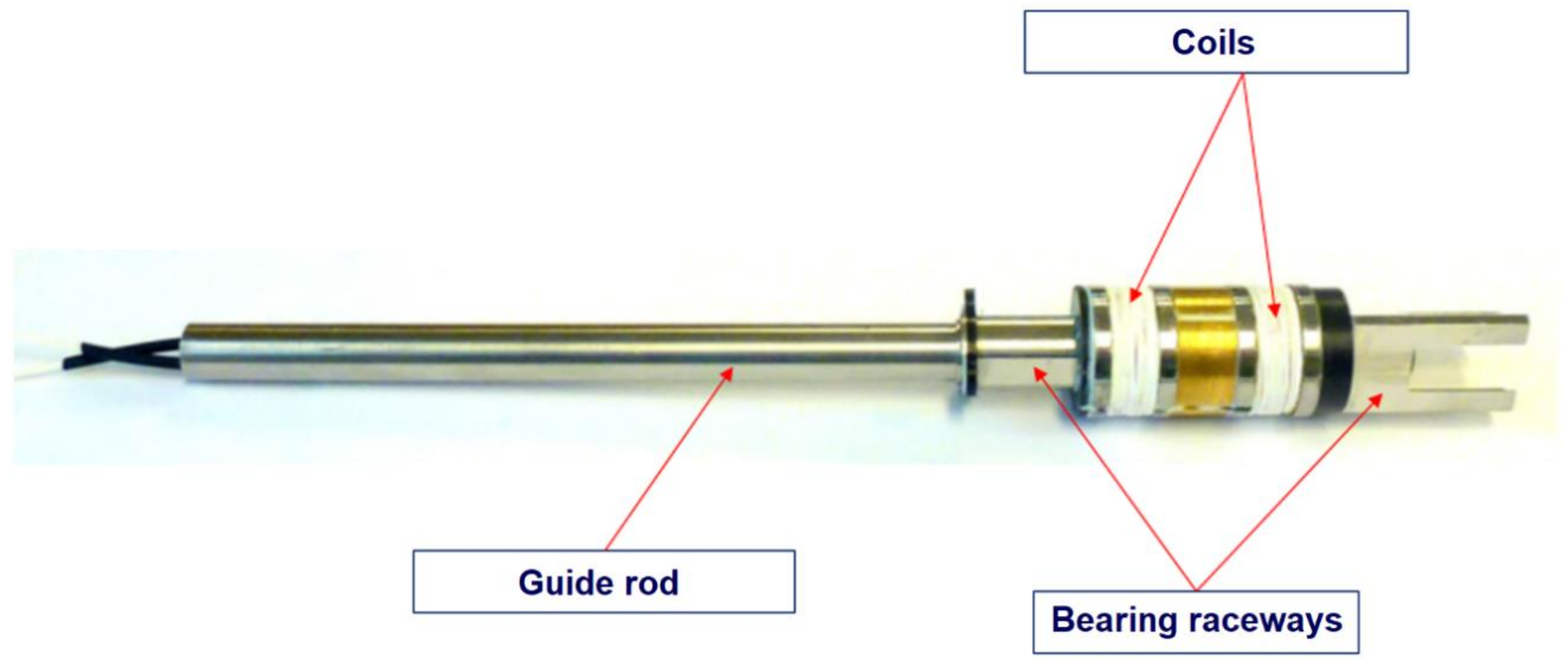
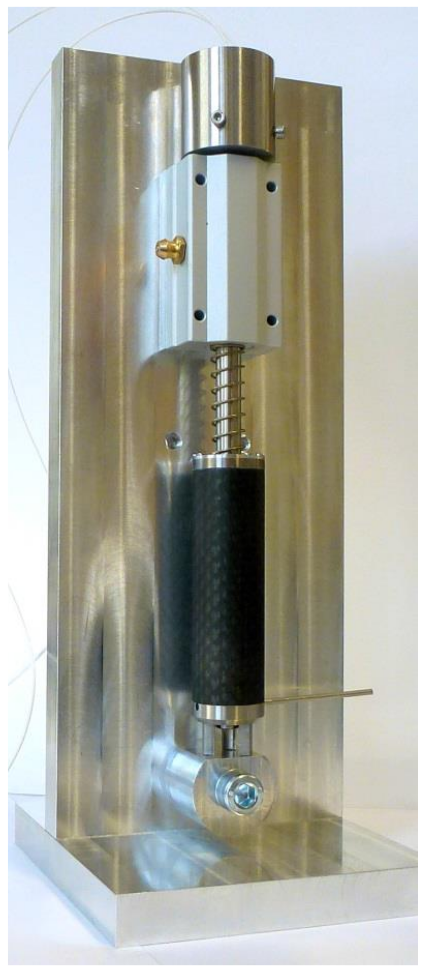
4. Laboratory Model of the Tube Reluctance Actuator
- Hammer (runner);
- Anvil;
- Counter-weight;
- Counter-mass return spring;
- Linear ball raceway.
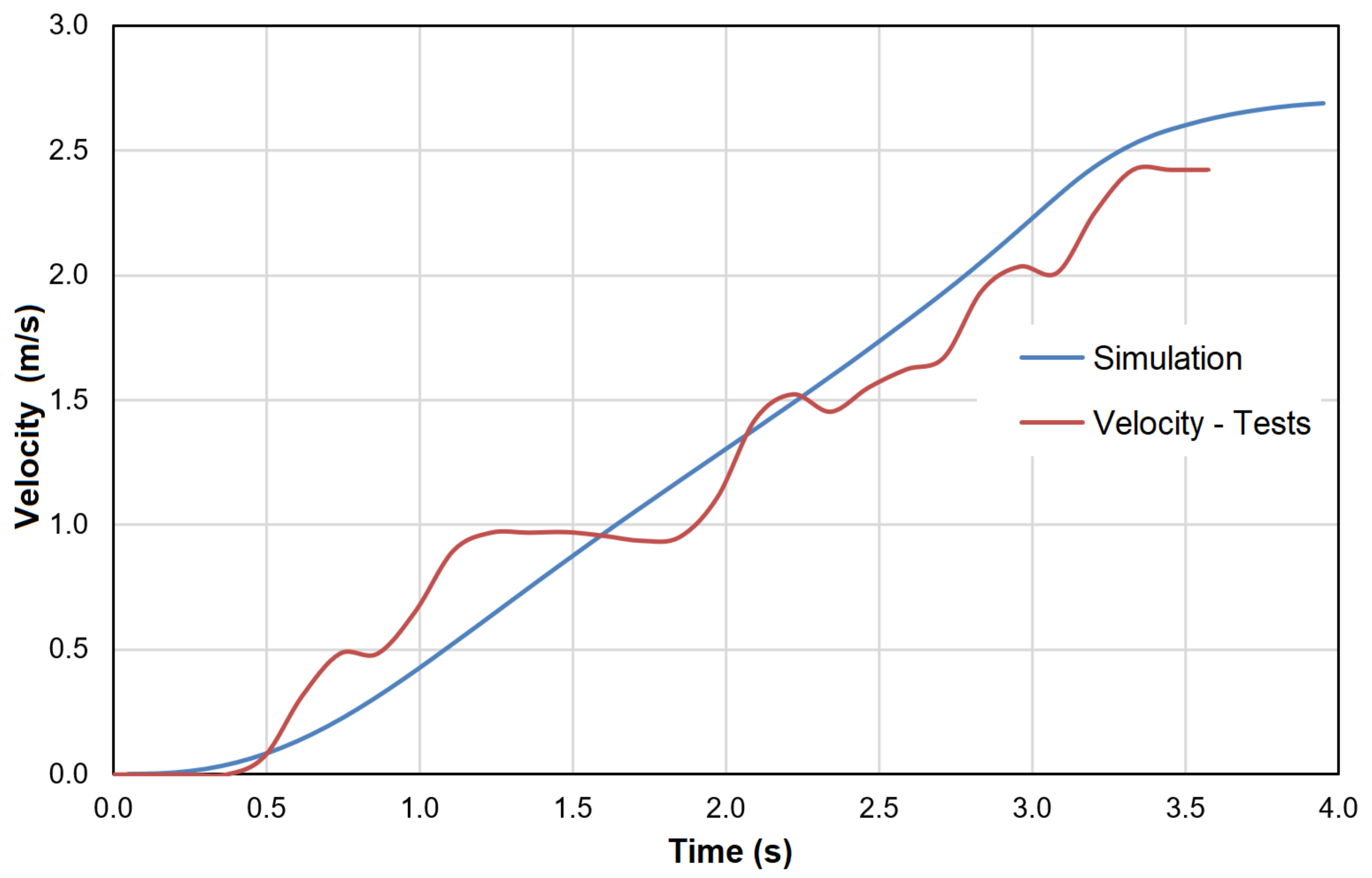
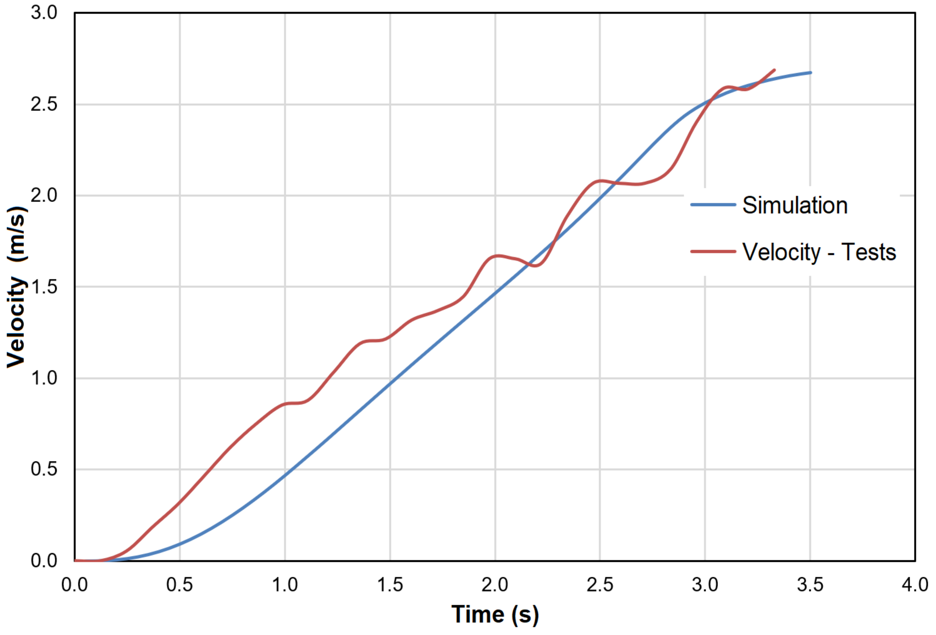
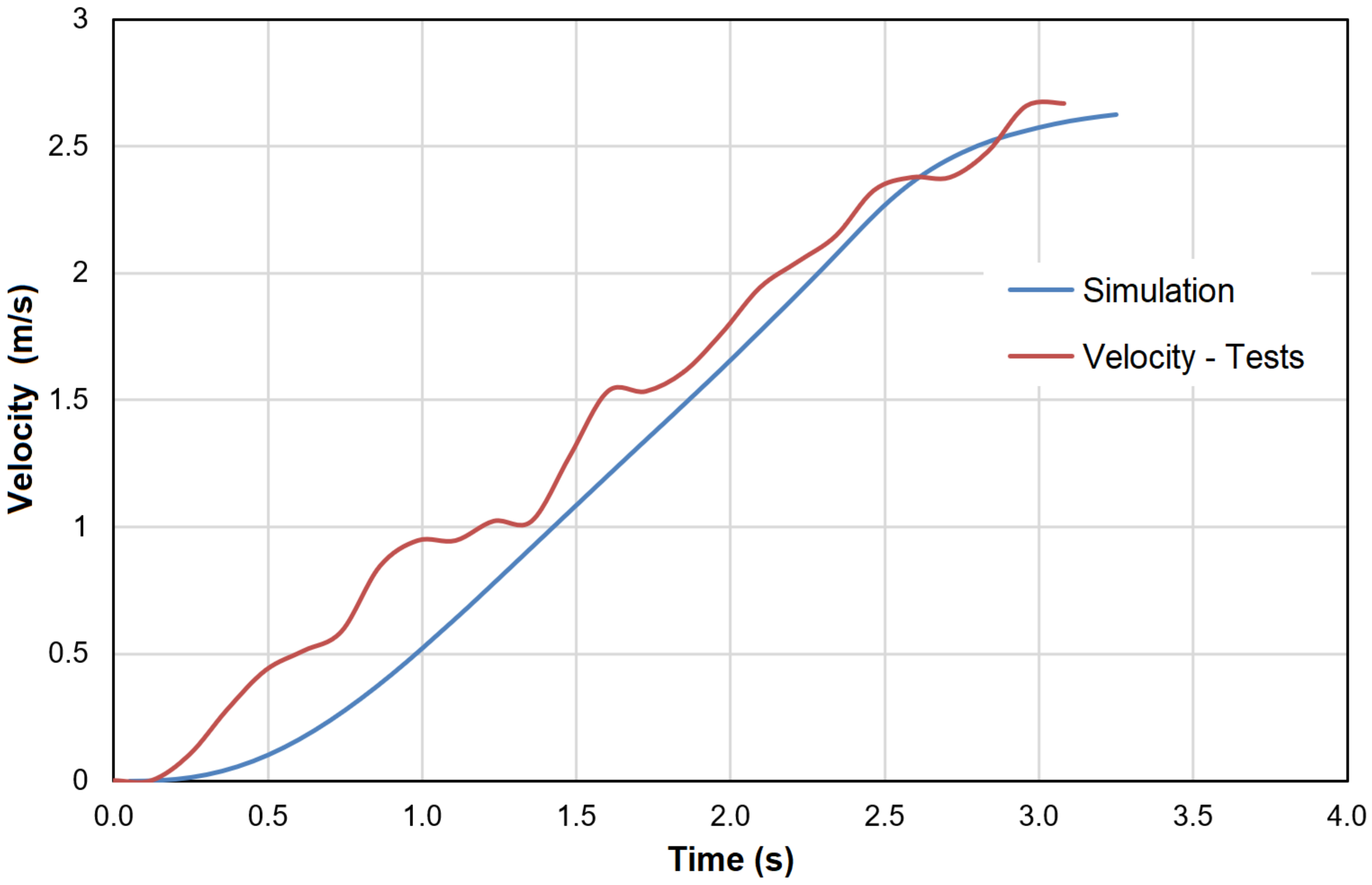
5. Laboratory Model Tests and Simulation Validity Check
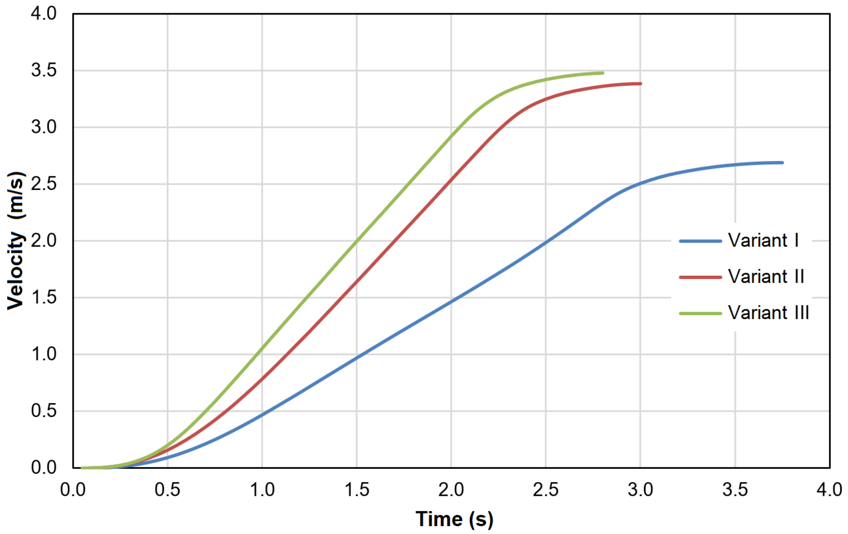
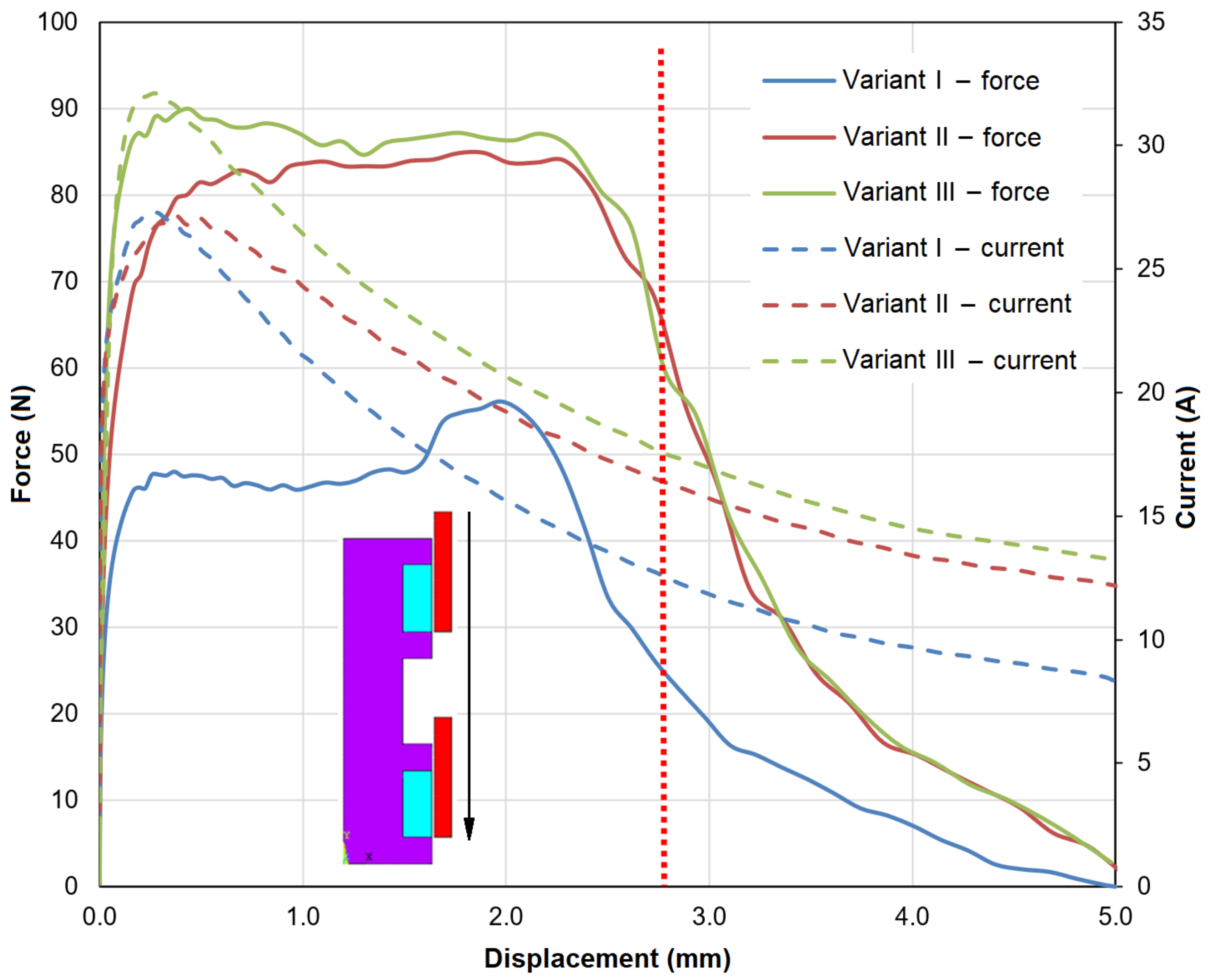
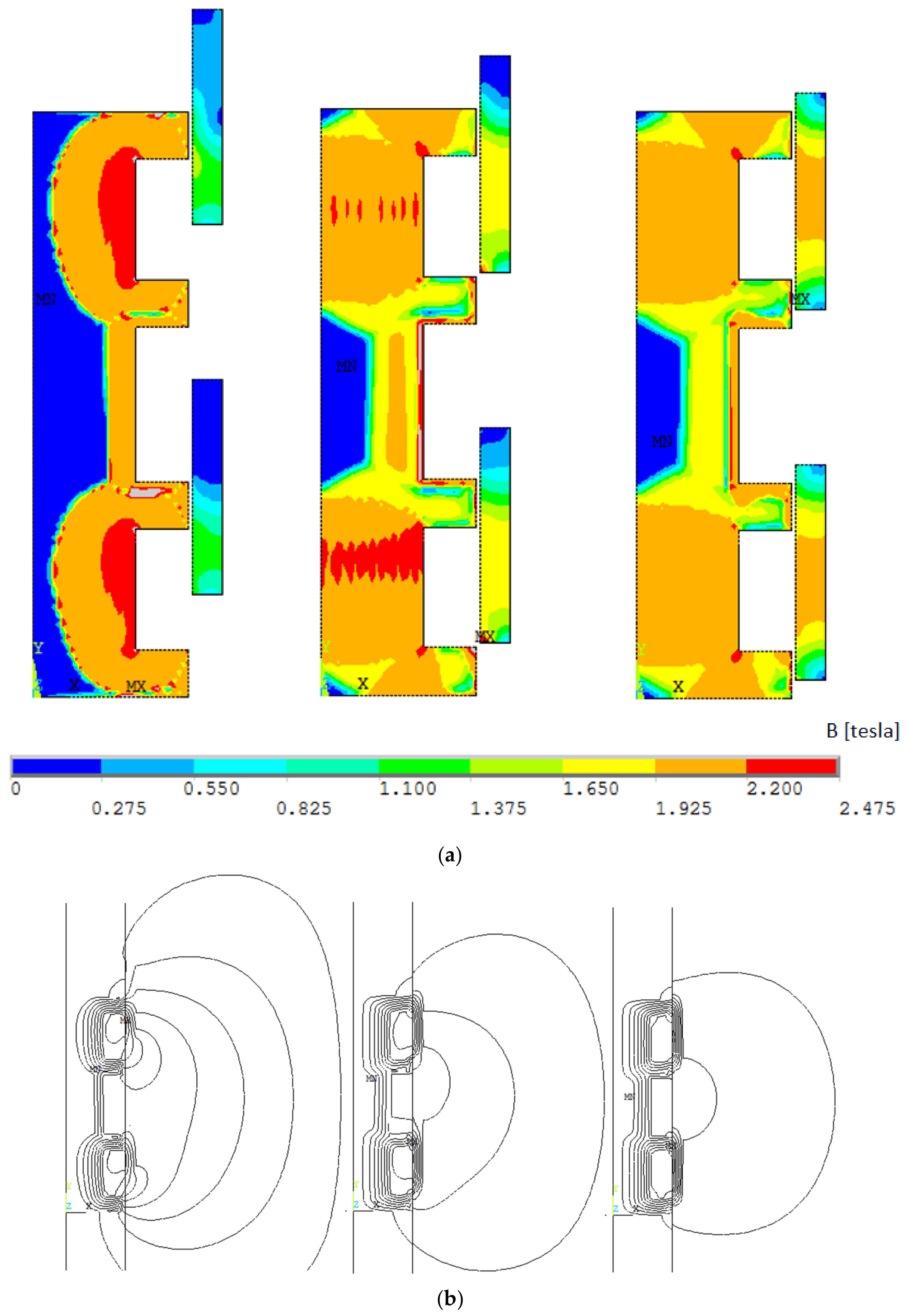
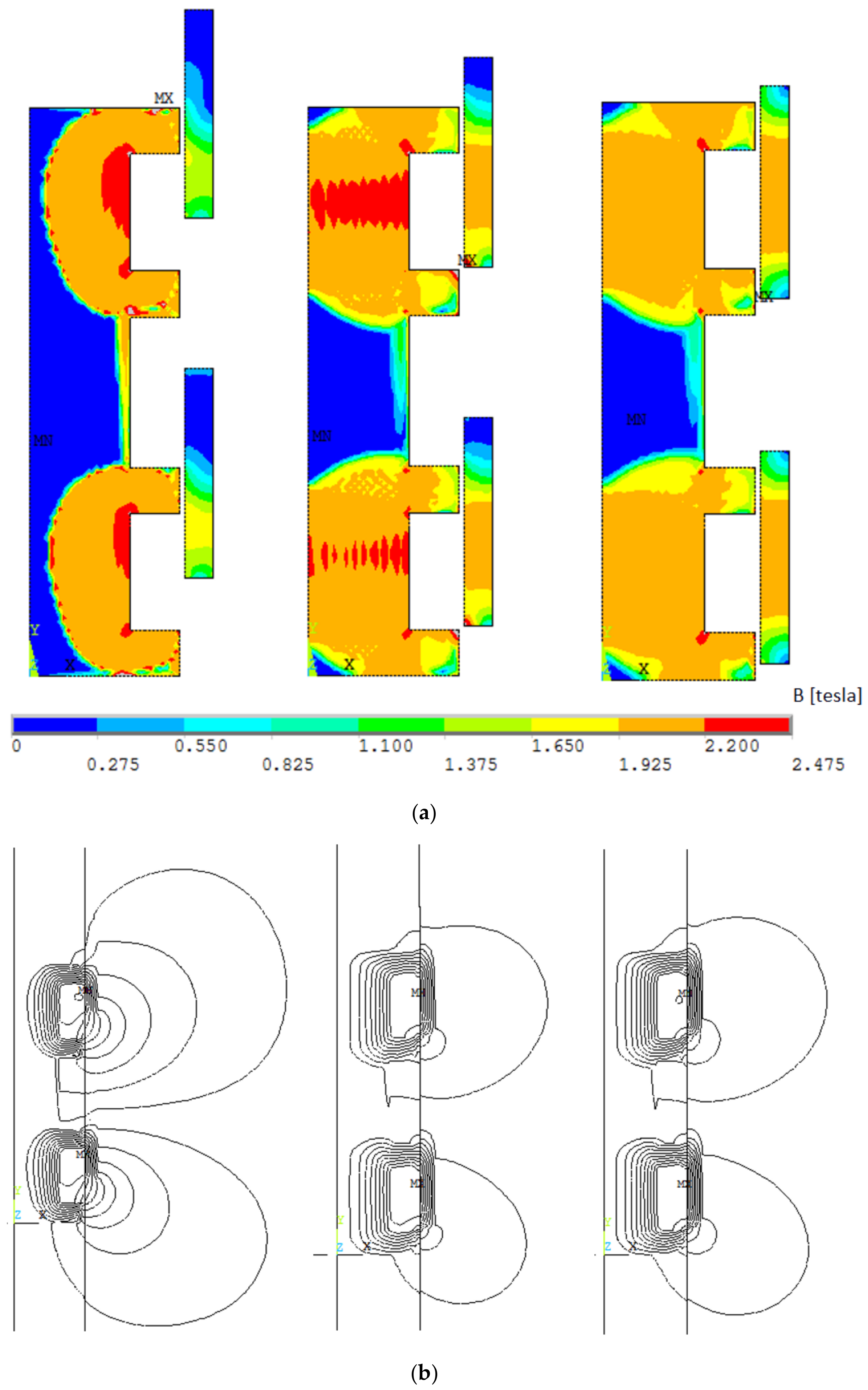
6. Analysis of Simulation Results
- Variant I:
- -
- Coils with the same return;
- -
- Taking into account eddy currents.
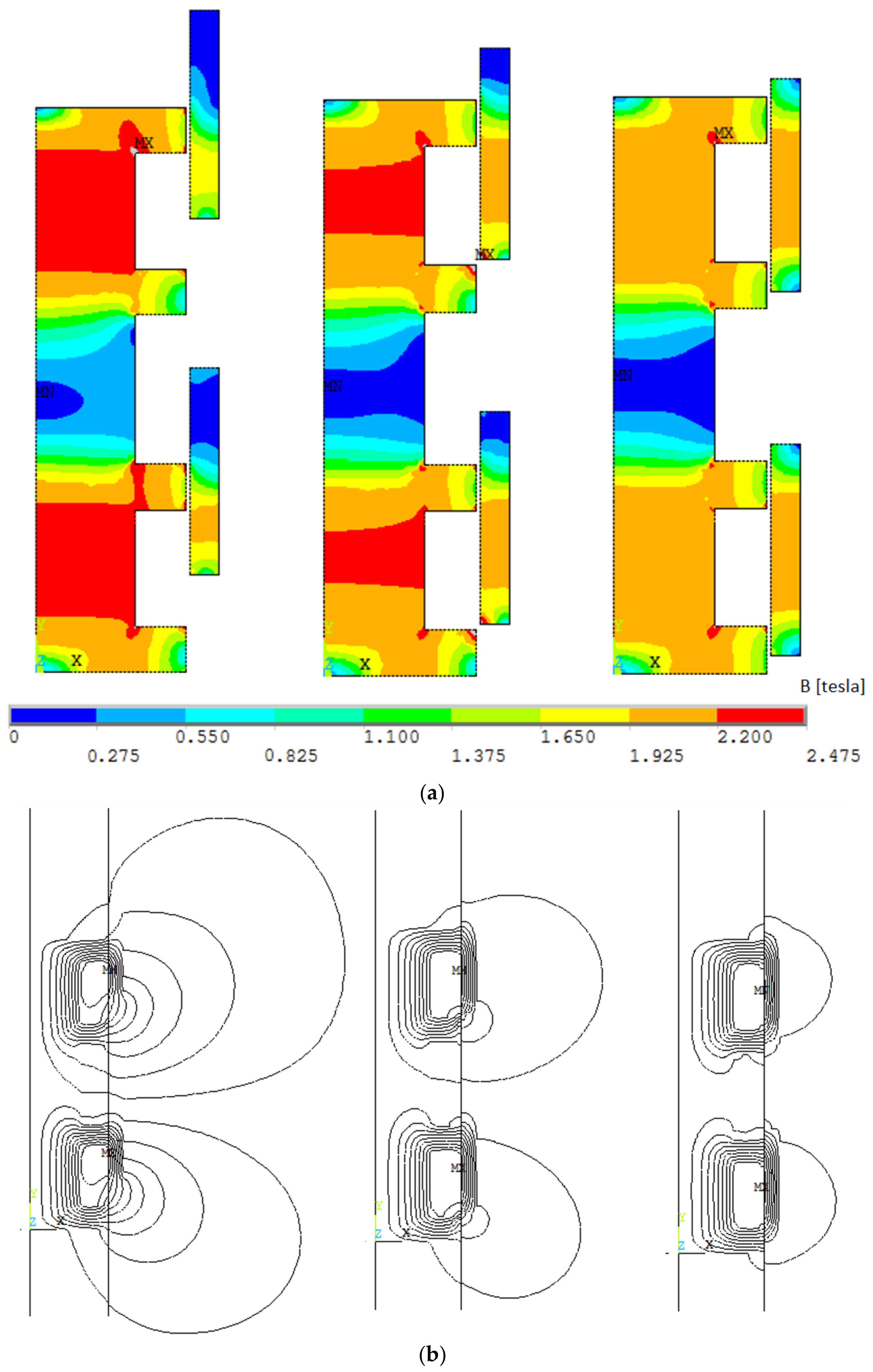
- Variant II:
- -
- Reverse coils;
- -
- Taking into account eddy currents.
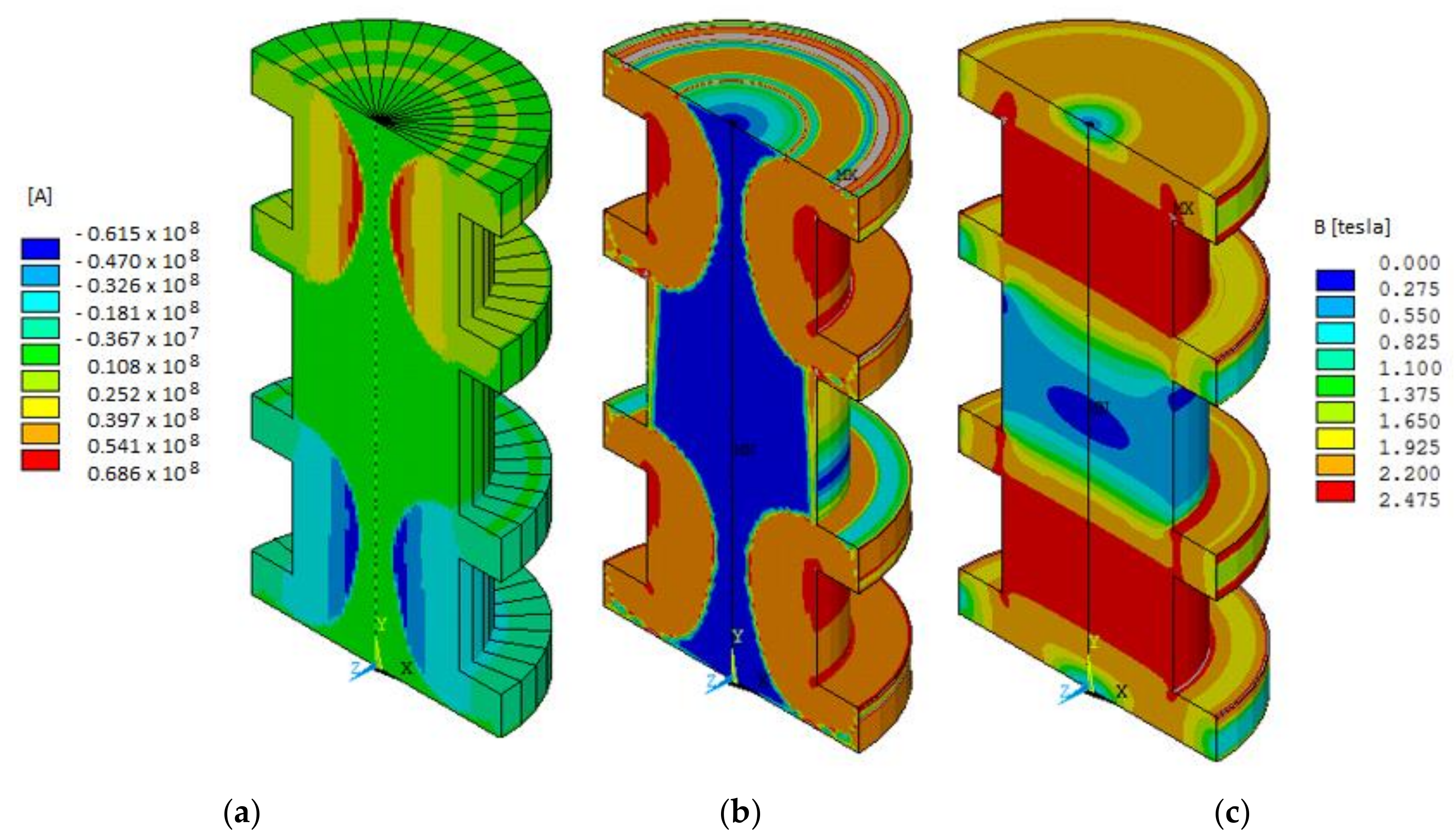
- Variant III:
- -
- Reverse coils;
- -
- Bypassing eddy currents.
7. Conclusions
Author Contributions
Funding
Conflicts of Interest
References
- Grygorczuk, J.; Banaszkiewicz, M.; Cichocki, A.; Ciesielska, M.; Dobrowolski, M.; Kędziora, B.; Krasowski, J.; Kuciński, T.; Marczewski, M.; Morawski, M.; et al. Advanced Penetrators and Hammering Sampling Devices for Plaetary Body Exploration. In Proceedings of the ASTRA Conference ESA/ESTEC, Noordwijk, The Netherlands, 12 April 2011. [Google Scholar]
- Grygorczuk, J.; Banaszkiewicz, M.; Seweryn, K.; Spohn, T. MUPUS Insertion device for the Rosetta mission. J. Telecommun. Inf. Technol. 2007, 1, 50–53. [Google Scholar]
- Coste, P. Mobile penetrometer ground tests. In Proceedings of the 5th ESA Workshop on Advanced Space Technologies for Robotics and Automation-‘ASTRA 1998’, ESTEC, Noordwijk, The Netherlands, 1–3 December 1998. [Google Scholar]
- Richter, L.; Coste, P.; Gromov, V.V.; Kochan, H.; Nadalini, R.; Ng, T.C.; Pinna, S.; Richter, H.E.; Yung, K.L. Development and testing of subsurface sampling devices for the Beagle–2 lander. Planet. Space Sci. 2002, 50, 903–913. [Google Scholar] [CrossRef]
- Knollenberg, J.; Nadalini, R.; Spohn, T. Thermal measurements with HP3/TEM on ExoMars. Geophys. Res. Abstr. 2007, 9, 441–447. [Google Scholar]
- Mirzaee, M.; Hooshmand, P.; Ahmadi, H.; Balotaki, H.K.; KhakRah, H.; Jamalabadi, M.Y.A. Electromagnetohydrodynamic Effects on Steam Bubble Formation in Vertical Heated Upward Flow. Energies 2016, 9, 657. [Google Scholar] [CrossRef] [Green Version]
- Ma, F.; Yin, H.; Wei, L.; Wu, L.; Gu, C. Analytical Calculation of Armature Reaction Field of the Interior Permanent Magnet Motor. Energies 2018, 11, 2375. [Google Scholar] [CrossRef] [Green Version]
- Kolimas, Ł.; Łapczyński, S.; Szulborski, M.; Świetlik, M. Low Voltage Modular Circuit Breakers: FEM Employment for Modelling of Arc Chambers. Bull. Pol. Acad. Sci. Tech. Sci. 2020, 68, 1–10. [Google Scholar]
- Nadalini, R.; Spohn, T.; Ambrosi, R.; Ball, A.J.; Frasier, G.; Grzesik, A.; Hagermann, A.; Hall, C.; Knollenberg, J.; Lichopoj, A.; et al. The Heat flow and Physical Properties Package (HP3) an integrated sensor suite for planetary subsurface investigations. Geophys. Res. Abstr. 2006, 8, 5. [Google Scholar]
- Banerdt, B.; Smrekar, S.; Dehant, V.; Lognonné, P.; Spohn, T.; Grott, M. GEMS (GEophysical Monitoring Station). In Proceedings of the EPSC-DPS Joint Meeting, Nantes, France, 7 October 2011. [Google Scholar]
- Stoker, C.R.; Richter, L.; Smith, W.H.; Lemke, L.G.; Hammer, P.; Dalton, J.B.; Glass, B.; Zent, A. The Mars Underground Mole (MUM): A Subsurface Penetration Device with In Situ Infrared Reflectance and Raman Spectroscopic Sensing Capability. In Proceedings of the 34th Annual Lunar and Planetary Science Conference, League City, TX, USA, 12 March 2003. [Google Scholar]
- Kolimas, Ł.; Łapczyński, S.; Szulborski, M. Tulip contacts: Experimental studies of electrical contacts in dynamic layout with the use of FEM software. Int. J. Electr. Eng. Educ. 2019, 1, 1–4. [Google Scholar] [CrossRef]
- Gromov, V.V.; Misckevich, A.V.; Yudkin, E.N.; Kochan, H.; Coste, P.; Re, E. The mobile penetrometer, a “mole“ for sub-surface soil investigation. In Proceedings of the 7th European Space Mechanisms & Tribology Symposium, ESTEC, Noordwijk, The Netherlands, 10 October 1997. [Google Scholar]
- Grygorczuk, J.; Banaszkiewicz, M.; Kargl, G.; Kömle, N.; Ball, A.J.; Seweryn, K. Use of hammering to determine cometary nucleus mechanical properties. Penetrometry in the Solar System II. In Proceedings of the 2nd International Workshop on Penetrometry in the Solar System, Graz, Austria, 1–4 September 2009; Austrian Academy of Sciences Press: Berlin, Germany, 2009; pp. 93–107. [Google Scholar]
- Grygorczuk, J. Key Problems of Design, Modeling and Application of Cometary Auto Penetrator MUPUS (In Polish: Kluczowe Problem Projektowania, Modelowania i Aplikacji Autopenetratora Kometarnego MUPUS). Ph.D. Thesis, Faculty of Power and Aeronautical Engineering, Warsaw University of Technology, Warsaw, Poland, 2010. [Google Scholar]
- Grygorczuk, J.; Seweryn, K.; Wawrzaszek, R.; Banaszkiewicz, M. Technological features in the new mole penetrator ‘KRET’. In Proceedings of the 13th European Space Mechanisms and Tribology Symposium (ESMATS), Vienna, Austria, 23 September 2009. [Google Scholar]
- Grygorczuk, J.; Kędziora, B.; Tokarz, M.; Seweryn, K.; Banaszkiewicz, M.; Dobrowolski, M.; Łyszczek, P.; Rybus, T.; Sidz, M.; Skup, K.; et al. Ultra-Light Planetary Manipulator-Study and Development. Submitted to: Geoplanet: Earth and Planetary Science; Springer: Berlin/Heidelberg, Germany, 2012. [Google Scholar]
- Grygorczuk, J.; Dobrowolski, M.; Wisniewski, L.; Banaszkiewicz, M.; Ciesielska, M.; Kedziora, B.; Seweryn, K.; Wawrzaszek, R.; Wierzchon, T.; Trzaska, M.; et al. Advanced mechanisms and tribological tests of the hammering sampling device CHOMIK. In Proceedings of the 14th European Space Mechanisms and Tribology Symposium (ESMATS), Constance, Germany, 28 September 2011. [Google Scholar]
- Glassmeier, K.H.; Boehnhardt, H.; Koschny, D.; Kührt, E.; Richter, I. The Rosetta Mission: Flying Towards the Origin of the Solar System. Space Sci. Rev. 2007, 128, 1–21. [Google Scholar] [CrossRef]
- Banaszkiewicz, M.; Seweryn, K.; Wawrzaszek, R. Thermal conductivity determination of cometary and asteroid materials. Adv. Space Res. 2007, 40, 226–237. [Google Scholar] [CrossRef]
- Spohn, T.; Seiferlin, K.; Hagermann, A.; Knollenberg, J.; Ball, A.J.; Banaszkiewicz, M.; Benkhoff, J.; Gadomski, S.; Grygorczuk, J.; Hlond, M.; et al. MUPUS–A Thermal and Mechanical Properties Probe for the Rosetta Lander PHILAE. Space Sci. Rev. 2007, 128, 339–362. [Google Scholar] [CrossRef]
- Grygorczuk, J.; Seweryn, K.; Banaszkiewicz, M.; Ciesielska, M.; Dobrowolski, M.; Kędziora, B.; Rybus, T.; Sidz, M.; Tokarz, M.; Wawrzaszek, R. MUPUS, CHOMIK AND KRET Penetrators as Examples of Mechanisms Used as End-Effectors of Manipulators in Space Exploration Missions. Pr. Nauk. Elektron. Pos. Robot. 2012, z.182, 503–512. (In Polish) [Google Scholar]
- Seweryn, K.; Banaszkiewicz, M.; Bednarz, S.; Gonet, A.; Grygorczuk, J.; Rybus, T.; Rzyczniak, M.; Wawrzaszek, R.; Wisniewski, L.; Wojcikowski, M. Mole Penetrator ‘KRET’ for 446 Lunar Exploration. In Proceedings of the 42th Lunar and Planetary Science Conference, The Woodlands, TX, USA, 7–11 March 2011. [Google Scholar]
- Gurgurewicz, J.; Rickman, H.; Królikowska, M.; Banaszkiewicz, M.; Grygorczuk, J.; Morawski, M.; Seweryn, K.; Wawrzaszek, R. Phobos investigations using the CHOMIK device (Phobos Sample Return mission). In Proceedings of the First Moscow Solar System Symposium, Moscow, Russia, 11–15 October 2010. [Google Scholar]
- Grygorczuk, J.; Seweryn, K.; Rickman, H.; Morawski, M.; Aleksashkin, S.N.; Banaszkiewicz, M.; Ciesielska, M.; Dobrowolski, M.; Drogosz, M.; Gurgurewicz, J.; et al. CHOMIK sampling device for Russian Phobos Sample Return Mission. In Proceedings of the First Moscow Solar System Symposium, Moscow, Russia, 11–15 October 2010. [Google Scholar]
- Seweryn, K.; Aleksashkin, S.N.; Banaszkiewicz, M.; Cichocki, A.; Ciesielska, M.; Dobrowolski, M.; Gurgurewicz, J.; Grygorczuk, J.; Kędziora, B.; Krasowski, J.; et al. The CHOMIK Instrument for Phobos-Grunt Mission-Functional Test and Calibration Data. In Proceedings of the 2nd Moscow Solar System Symposium, Moscow, Russia, 26 August 2011. [Google Scholar]
- Dabrowski, B.; Banaszkiewicz, M. Measurement of lunar and Martian regolith thermal properties using subsurface robotic teams. In Proceedings of the 9th ESA Workshop on Advanced Space Technologies for Robotics and Automation, Noordwijk, The Netherlands, 28–30 November 2006. [Google Scholar]
- Surkov, Y.A.; Kremnev, R.S. Mars-96 mission: Mars exploration with the use of penetrators. Planet. Space Sci. 1998, 46, 1689–1696. [Google Scholar] [CrossRef]
- Lorenz, R.D.; Moersch, J.E.; Stone, J.A.; Morgan, A.R., Jr.; Smrekar, S.E. Penetration tests on the DS-2 Mars microprobes: Penetration depth and impact accelerometry. Planet. Space Sci. 2000, 48, 419–436. [Google Scholar] [CrossRef] [Green Version]
- Nakajima, T.; Hinada, M.; Saitoh, H.; Kawaguchi, J.I.; Akio, F. Lunar penetrator program: Lunar-A. Acta Astronaut. 1996, 39, 111–119. [Google Scholar] [CrossRef]
- Lichtenheldt, R. Hammering beneath the surface of Mars-modeling and simulation of the impact-driven locomotion of the HP3-Mole by coupling enhanced multi-body dynamics and discrete element method. In Proceedings of the 58th Ilmenau Scientific Colloquium, Ilmenau, Germany, 8–12 September 2014; pp. 155–174. [Google Scholar]
- Nagaoka, K.; Kubota, T.; Otsuki, M.; Tanaka, S. Experimental study on autonomous burrowing screw robot for subsurface exploration on the Moon. Intell. Robot. Syst. 2008, 4, 4104–4109. [Google Scholar]
- Lu, Z.S.; Cao, D.H. Simulation analysis for physical model of stick-slip. Chin. J. Mech. Eng. 2004, 40, 107–112. [Google Scholar] [CrossRef]
- Liu, L.L.; Liu, H.Z.; Wu, Z.Y.; Wang, Z.M. An overview of friction models in mechanical systems. Adv. Mech. 2008, 38, 201–213. [Google Scholar]
- Grygorczuk, J.; Banaszkiewicz, M.; Seweryn, K.; Wiśniewski, Ł.; Wawrzaszek, R. Space Penetrators- Rosetta case study. In Proceedings of the 18th International Conference on Methods & Models in Automation & Robotics (MMAR), Międzyzdroje, Poland, 26–29 August 2013. [Google Scholar]
- Shen, Y.; Jiang, S.; Xu, C.; Zhang, W.; Wu, X. Study on Optimization of Structure Parameters to the Penetrator. In Proceedings of the IEEE International Conference on Mechatronics and Automation, Harbin, China, 7–10 August 2016. [Google Scholar]
- Barmpatza, A.C.; Kappatou, J.C. Finite Element Method Investigation and Loss Estimation of a Permanent Magnet Synchronous Generator Feeding a Non-Linear Load. Energies 2018, 11, 3404. [Google Scholar] [CrossRef] [Green Version]
- Grygorczuk, J.; Wiśniewski, Ł.; Banaszkiewicz, M.; Ciesielska, M.; Dobrowolski, M.; Kedziora, B.; Krasowski, J.; Przybyła, R.; Seweryn, K.; Tokarz, M.; et al. High energy and efficiency penetrator-heep. In Proceedings of the 15th European Space Mechanisms & Tribology Symposium-ESMATS 2013, Noordwijk, The Netherlands, 25–27 September 2013. [Google Scholar]


| Parameter | Value |
|---|---|
| Max. length of the actuator | 127 (mm) |
| The outer diameter of the actuator (H) | 22.7 (mm) |
| The total weight of the hammer | 120 (g) |
| Total counter-mass weight | 720 (g) |
| Energy stored in the capacitor | 21 (J) |
© 2020 by the authors. Licensee MDPI, Basel, Switzerland. This article is an open access article distributed under the terms and conditions of the Creative Commons Attribution (CC BY) license (http://creativecommons.org/licenses/by/4.0/).
Share and Cite
Bieńkowski, K.; Kolimas, Ł.; Łapczyński, S.; Drogosz, M.; Szulborski, M.; Wiśniewski, Ł.; Kędziora, B.; Kozarek, Ł. Simulations and Tests of a KRET Aerospace Penetrator. Energies 2020, 13, 3291. https://doi.org/10.3390/en13123291
Bieńkowski K, Kolimas Ł, Łapczyński S, Drogosz M, Szulborski M, Wiśniewski Ł, Kędziora B, Kozarek Ł. Simulations and Tests of a KRET Aerospace Penetrator. Energies. 2020; 13(12):3291. https://doi.org/10.3390/en13123291
Chicago/Turabian StyleBieńkowski, Krzysztof, Łukasz Kolimas, Sebastian Łapczyński, Michał Drogosz, Michał Szulborski, Łukasz Wiśniewski, Bartosz Kędziora, and Łukasz Kozarek. 2020. "Simulations and Tests of a KRET Aerospace Penetrator" Energies 13, no. 12: 3291. https://doi.org/10.3390/en13123291