Article

Retrofit Methodology Based on Energy Simulation Modeling Applied for the Enhancement of a Historical Building in L’Aquila

by
Mariangela De Vita
1,*,
Giulia Massari
2 and
Pierluigi De Berardinis
2
1
Construction Technologies Institute CNR, Via G. Carducci 32 C, 67100 L’Aquila, Italy
2
Department of Civil, Architectural Construction and Environmental Engineering, University of L’Aquila, 67100 L’Aquila, Italy
*
Author to whom correspondence should be addressed.
Energies 2020, 13(12), 3289; https://doi.org/10.3390/en13123289
Submission received: 27 April 2020 / Revised: 18 June 2020 / Accepted: 23 June 2020 / Published: 26 June 2020

Abstract

:
Energy loss has not been addressed effectively by policies introduced to encourage the preservation and enhancement of historical structures. Material and other constraints, together with safety standard improvements, do not always guarantee adequate levels of environmental performance. An optimization of retrofit measures to align with new uses, new standards of comfort, and energy saving are needed, as are studies based on new best practices for the enhancement of architectural heritage. This paper presents a method that uses dynamic models tared on non-destructive surveys, and based on compatible energy and structural interventions derived from preliminary analyses integrated into special design tools. Energy simulations were carried out using Design Builder (6.1.5.002, Designbuilder Software Ltd, Stroud, UK) software. The case study is a former hospital, S. Salvatore, in L’Aquila, an architecturally important building, severely damaged by an earthquake in 2009. The methodology presented in this research includes in-depth investigations coherently systematized into a multi-scenario output using simulation software. The results guarantee a high level of compatibility with restoration and seismic guidelines, and new building environmental performance requirements.

1. Introduction

Existing buildings are responsible for 34% of global energy consumption and 19% of global energy-related greenhouse gas emissions [1,2]. In Europe, the building stock accounts for 41% of CO2 emissions [3] and this figure is expected to continue to rise [4,5]. The EU has introduced legislation to boost energy performance in buildings: the Energy performance of buildings directive 2010/31/EU (EPBD), the Energy efficiency directive 2012/27/EU [6,7], and most recently, the revised Energy performance of buildings directive 2018/844/EU, which introduces new elements to modernise the buildings sector in light of technological advancements, and measures to accelerate and encourage building renovation [7]. Amongst existing buildings, historical ones have the greatest potential in terms of improving environmental performance and consequently best practice methodologies for their restoration and requalification have been the focus of a lot of international research [3,8,9,10,11].
One of the main points of reference for best practice is the International Council on Monuments and Sites (ICOMOS). In 2003, ICOMOS defined the ‘Principles for the analysis, conservation and structural restoration of architectural heritage’ publishing a charter and related guidelines [12] based on the principles enshrined in the 1964 Venice Charter [13]. These guidelines address issues related to the conciliation of structural and conservation needs. These documents represent a fundamental vade mecum for designers in the restoration and enhancement of cultural heritage, however they do not address the environmental issues that we face today.
The European standard EN-16883 [14] is also an important tool in retrofitting, and there are numerous guidelines for energy retrofitting of historic and traditional buildings [15] but there are still a number of difficulties reconciling the need to improve performance with those of safeguarding the historical patrimony. In fact, one of the reasons behind the scarce improvement in the energy performance of existing buildings is that current legislation does not take into account the complexity of interventions on structures making up the architectural heritage [15]. The shortcomings highlighted in official national and international guidelines have prompted research into retrofit methodology, investigating best practice and optimization procedures.
Previous research has looked at the impact of retrofit actions [10,16] by comparing and developing procedures and protocols [15,17], and studying the effectiveness of recent government energy policies [18,19,20]. Numerous studies have been based on modeling and dynamic simulations to verify the expected outcome of retrofit interventions [16,21,22,23,24] whilst others have confirmed that basing simulation models on in-situ analysis and non-destructive surveys-performed with thermal cameras, sonic tests and thermalflowximeter–is a valid means of obtaining reliable results [21,22,25]. In short, many studies highlight the need to identify new design methodologies rather than new retrofit techniques, and put forward various solutions [15,16,26,27,28]. One interesting piece of research [29] also worth mentioning puts forward a best practice interdisciplinary methodology with a focus on economic feasibility.
However, these studies lack energy-optimized procedures that take into account restoration issues, damage and decay evaluations, compatible with structural interventions. Furthermore, they do not tackle conflicting aspects: some procedures focus on energy gain without cross checks for constraints [26] or evaluating transformability in terms of value or damage [27]; whilst others prioritize the payback period [16]. Overall, there is no mention of the combined effect of decay and structural damage on the energy retrofit procedure and restoration.
Indeed, structural and restoration interventions have a great impact on the choice of retrofit measures, determining the typology and extent. This is especially relevant in Italy where earthquakes cause significant damage requiring large-scale interventions that can incorporate significant energy solutions, unlike non-seismic areas where massive interventions may not be acceptable or feasible. Given Italy’s position on the UNESCO World Heritage Sites list [30] and its susceptibility to seismic events, it is an excellent source of case studies for new retrofit procedures combining restoration with structural/energy improvements.
The aim of this research is therefore to define a retrofit methodology that incorporates and optimizes the previously mentioned guidelines and research into a single procedure. This methodology will take into account the preliminary analyses of the case study, the energy audit and the state of damage and vulnerability (structural and non-structural) of the building, to define intervention strategies compatible with all retrofit aspects. The last step in the process is an energy simulation for the compatible scenarios identified and is based on a model built using non-destructive surveys.
As mentioned earlier, the methodology presented is applied to a former hospital, belonging to the University of L’Aquila. The building represents a particularly interesting challenge given its historical and social value, the extensive restructuring needed as a result of the damage it suffered in the 2009 earthquake, and the plans for its future use: a student residence with numerous areas intended for cultural and leisure activities. Its current state has been the subject of much study and research, including cost-benefit analyses [31,32,33]. Accordingly, this paper represents the last step in this research process: the definition of a scientific pathway for its rehabilitation.

2. Materials and Methods

This section describes the context of the intervention in terms of the masonry/structure reference type and the methodology followed. The tools necessary for identifying the correct methodology and optimizing retrofit procedures are also described.

2.1. Historical Masonry Building: Constraints and Improving Performance

Natural stone is one of the most ancient materials used in building construction and there are a significant number of historical centres characterized by this material, which contributes not only to the identity of the city, but also its territory and landscape. A number of these historical centers are listed among the UNESCO world heritage sites [34]; in Italy, the Ministry of cultural heritage (MiBAC) extends the concept of “monumental buildings” to ordinary historical buildings that together form ancient villages as well as small, historical towns that constitute and reflect Italy’s cultural heritage [35].
In recent years, a number of methodologies have been developed to retrofit and preserve historical masonry buildings and some of these techniques are based on the re-use of the same building materials used in the construction of these ancient envelopes [36,37,38]. In Italy, where most of the historical masonry buildings are constructed in high seismic risk areas, effective reconstruction techniques are used in the extensive re-building of towns after earthquakes. However, now, designers and structural engineers are also tasked with finding methods for preserving historic buildings in line with a Directive on cultural heritage [39] and to new technical standards (NTC 2018, Decreto Ministeriale 17 January 2018) [40]. Further legislation, the Decreto Ministeriale 11 October 2017 [41], has also defined minimum environmental criteria for public buildings, establishing new standards aimed at reducing land use and environmental cost.
The case study presented in this paper presents a number of challenges being a protected, public architectural complex with an unusual masonry construction: rows of bricks, reinforced with concrete pillars. This latter feature is of particular interest as its thermal and environmental characteristics combined with structural performance have never been investigated.

2.2. Historical Analysis, On Site Investigations, Non-Destructive Techniques and Simulation Software: Too Many Tools for a Coherent Retrofit Approach?
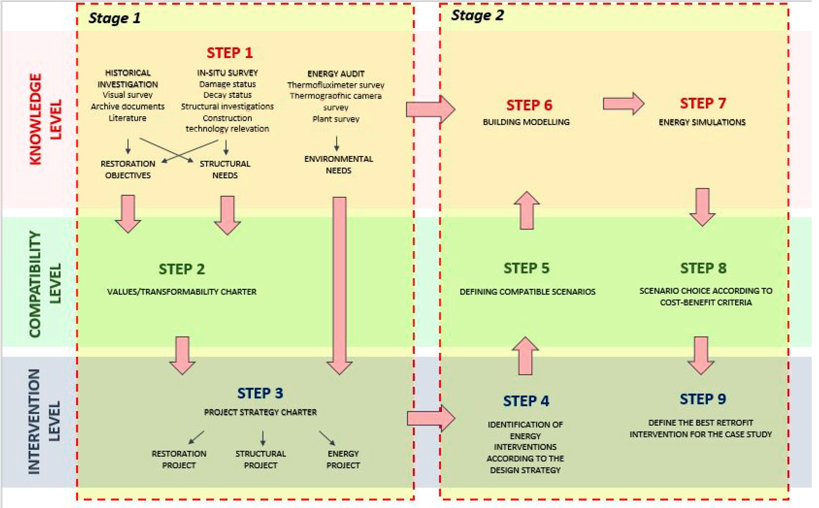
The main challenge of this research was to draw together very different approaches to restoration with the aim of ensuring an optimization of environmental issues in architectural heritage retrofitting. ICOMOS guidelines [13] set out to protect the cultural heritage: this research complies with these indications but also goes one step further: enriching the procedure with the use of additional diagnostic and control tools to improve environmental performance. ICOMOS guidelines are followed both in the sub-division of the project into iterative steps and in the use of an “overall integrated plan” and “program of control” that can be updated during the project and translated into specific design tools, described below.
The traditional approach to this type of project usually involves different professional figures: historians, restorers, structural engineers, and energy planners. This results in a large number of different analyses that can lead to contrasting interventions. The methodology proposed in this paper ensures the results of the various analyses communicate through tools that can harmonise approaches. This allows the designer to make choices that are coherent and compatible with all the identified project needs. The tools used consist of a values/transformability map, a project strategy map and environmental performance forecasts from energy simulations scenarios.
The first two tools are simple but essential and are used to carry out a critical analysis of the results of investigations into the building’s current state, and to provide general clear, design guidelines, in line with ICOMOS principles. The third tool, on the other hand is specific to our research. Dynamic simulations have been used for many years to predict the behaviour of buildings from an energy point of view and therefore to guide design. These simulations require modeling of the architectural and construction characteristics of the artifact, which are often elementary geometric schemes of the building under investigation. Dynamic simulations of this type are mainly used in new construction or to understand the effectiveness of single devices or single functions of a building: energy supply of HVAC (heating, ventilation and air conditioning) systems, greenhouses, ventilated facades, ventilation chimneys, courtyards, open spaces etc.
In the case of architectural heritage, in which buildings are always the result of a complex stratification of materials and construction techniques, the simplification of the models for dynamic simulations risks generating unreliable outputs [42]. Hence, in our method, modeling is enriched and supported by the analyses carried out during the preliminary investigation. By knowing the exact transmittance of the historical masonry and identifying defects such as structural discontinuities, we can generate more reliable models, as confirmed by authoritative scientific research that has used the same software and method [21,22,25]. The software used for modeling and performing dynamic simulations is Design Builder, the most used Energy Plus graphic interface. Although not the most sophisticated software available, it is a straightforward tool that is popular among scholars and practitioners, hence the reason for our choice of this tool in this research.

2.3. Methodology

As mentioned above, our main aim was to define a simple methodological path to guide a designer in the retrofitting of architectural heritage. This methodology takes different design approaches and produces intervention solutions that take into account all aspects of the process, including conflicting ones.
In fact, conflicting aspects often emerge in the specialized analyses carried out to gain an in-depth understanding of the building in its current state. This step usually involves a number of specialists from varying disciplines as historical, visual, constructive, structural and energy analyses are all required to define appropriate interventions.
A tool that is capable of assimilating this information into a coherent system is therefore invaluable. In our methodology, this tool is a values/transformability map. This interactive map assigns to constraints and features of value found in the building, a specific degree of transformability to be achieved by the intervention: so retrofit solutions are guided towards a project compatible with the restoration aims for the building.
The next stage is the definition of the retrofit objectives: a project strategy tool that must ensure that the objectives underlying the project are consistent and compatible with the constraints dictated by the values/transformability map. At this point in the process, we are able to direct the design towards the optimization of the building environmental performance and avoid conflict with the needs of static safety whilst safeguarding the building’s architectural value. There are normally a number of options, however optimal interventions require reversibility, cost-effectiveness and efficiency in terms of performance, as cost-benefit evaluations cannot be ignored.
Our methodology identifies different scenarios compatible with the preliminary analyses. The scenarios are tested using dynamic simulations to predict building performance around the modeling of different project interventions. The accuracy and completeness of the preliminary analyses enable the construction of simulation models able to provide an output with a negligible approximation degree for the purposes of the optimal retrofit choices.
The steps involved are summarized below:
Stage 1:
Step 1. Preliminary analyses by specialists: historical investigations, identification of architectural features of value, visual analyses, non-destructive surveys on the masonry (thermocamera and thermofluximeter surveys), damage studies, decay state readings, structural analyses, and energy audits.
Step 2. The drawing up of a value/transformability map that defines the features of value to preserve in each part of the building.
Step 3. Use of the project strategy map to define any macro-intervention categories common to all the disciplines involved: partial demolition, the replacement of some portions-structural or not-of the building, the addition of new elements, etc. This step requires the drawing up of the strategy to adopt in each part of the building.
Stage 2:
Step 4. The definition of the energy intervention aligned to the established target.
Step 5. The definition of all possible scenarios.
Step 6. Building modeling in line with the various intervention scenarios envisaged and on the basis of the results obtained from the preliminary analyses.
Step 7. Energy simulations for each model and scenario envisaged.
Step 8. Critical analysis of the results for the choice of the configuration according to cost-benefit criteria.
Step 9. Definition of the best retrofit intervention for the case under study.
The steps are divided into two stages as the first stage refers to operations that underlie any project output (structural retrofit, energy retrofit and restoration) whilst the second stage identifies optimal solutions for energy requalification.
The steps are mutually dependent, and this is highlighted in Figure 1.
The methodology allowed us to identify compatible retrofit interventions and the related scenarios, outlined later in Section 4, to be applied to the building in its current configuration to safeguard it from incompatible alterations. Although not recommended by the current guidelines on the energy retrofit of cultural heritage [43], our methodology also allowed for massive interventions justified in this case, by structural needs.
It is also worth underlining that energy simulation, step 7, is a tool that does not take into consideration the safeguarding of architectural features. However, the novelty of the methodology presented here is the incorporation of energy simulations in a pathway consistent with all the preliminary analyses and project aims, and this is made possible thanks to the use of values/transformability map and the project strategy map.
This methodology was tested on a portion of the building that had been extended in 1930. The same methodology will subsequently be applied to the whole architectural complex as part of a research project approved by the University in 2019. This research project is the outcome of a feasibility study on the conversion of the building into a student residence [31] involving the University of L’Aquila and the Construction Technologies Institute (L’Aquila) of the National Research Council (Italy) to which the Italian Government has allocated 52 million euros [44].
The methodology described here is the first result on the energy retrofitting of the site and the process described will ensure an optimization of the environmental performance of the building in relation to its future use.

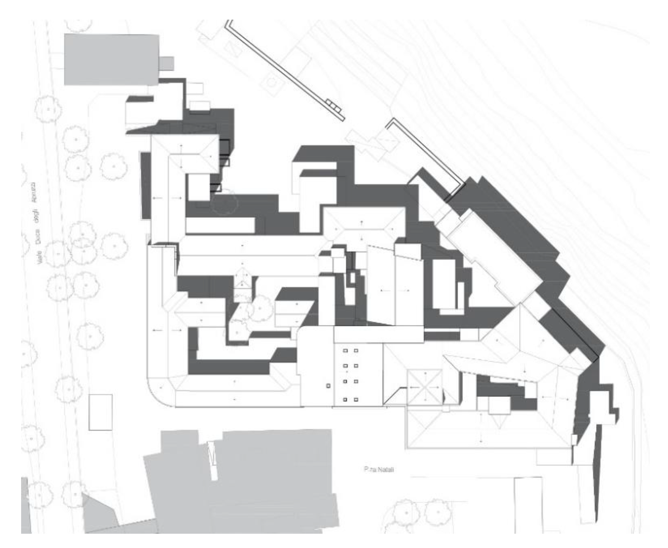
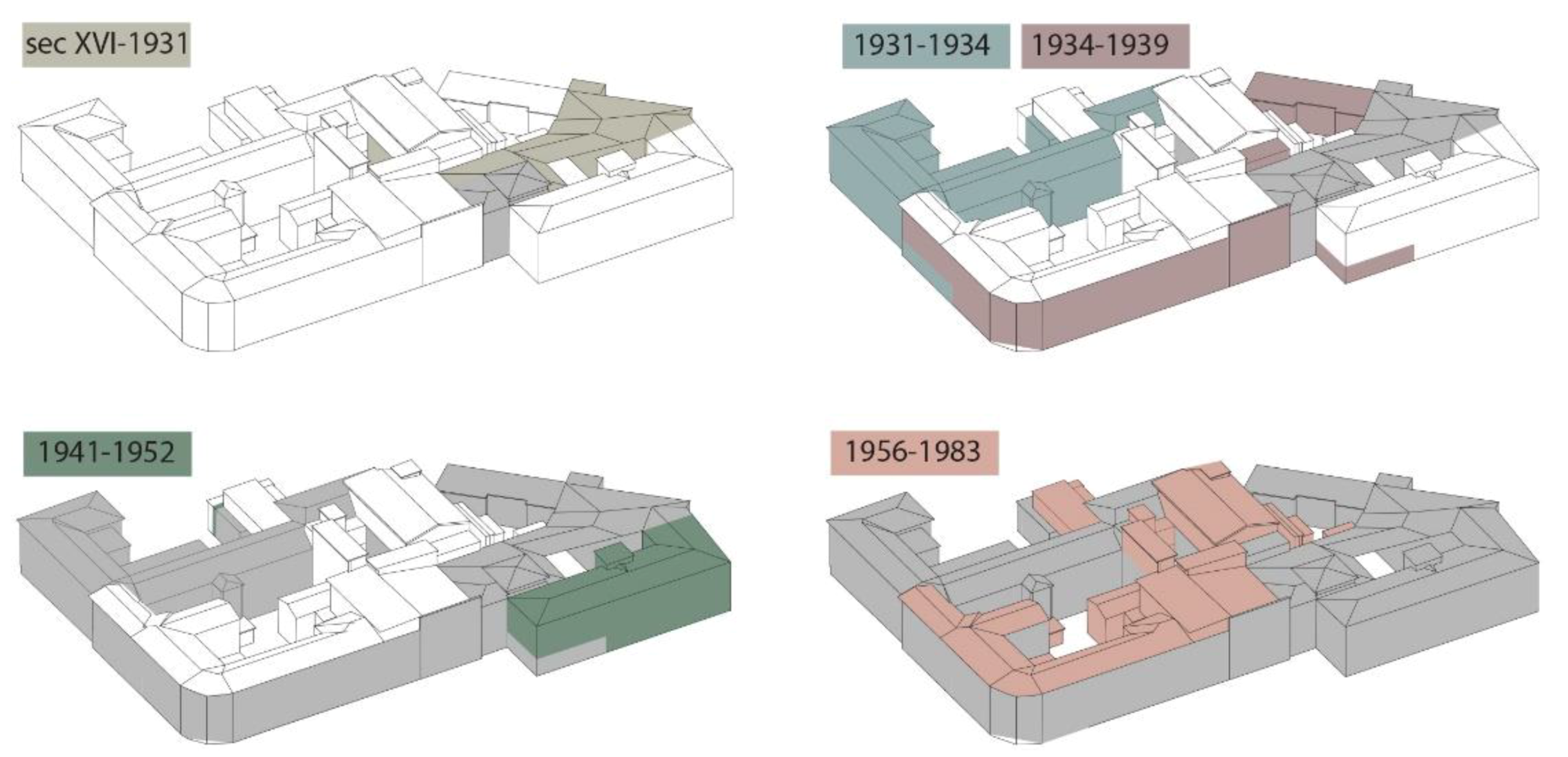
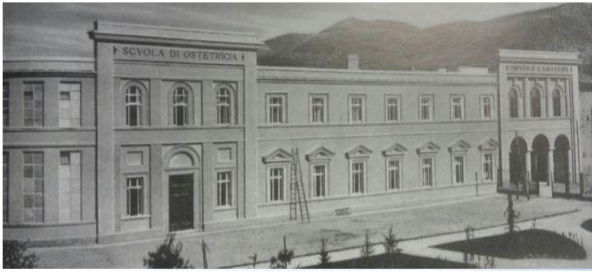
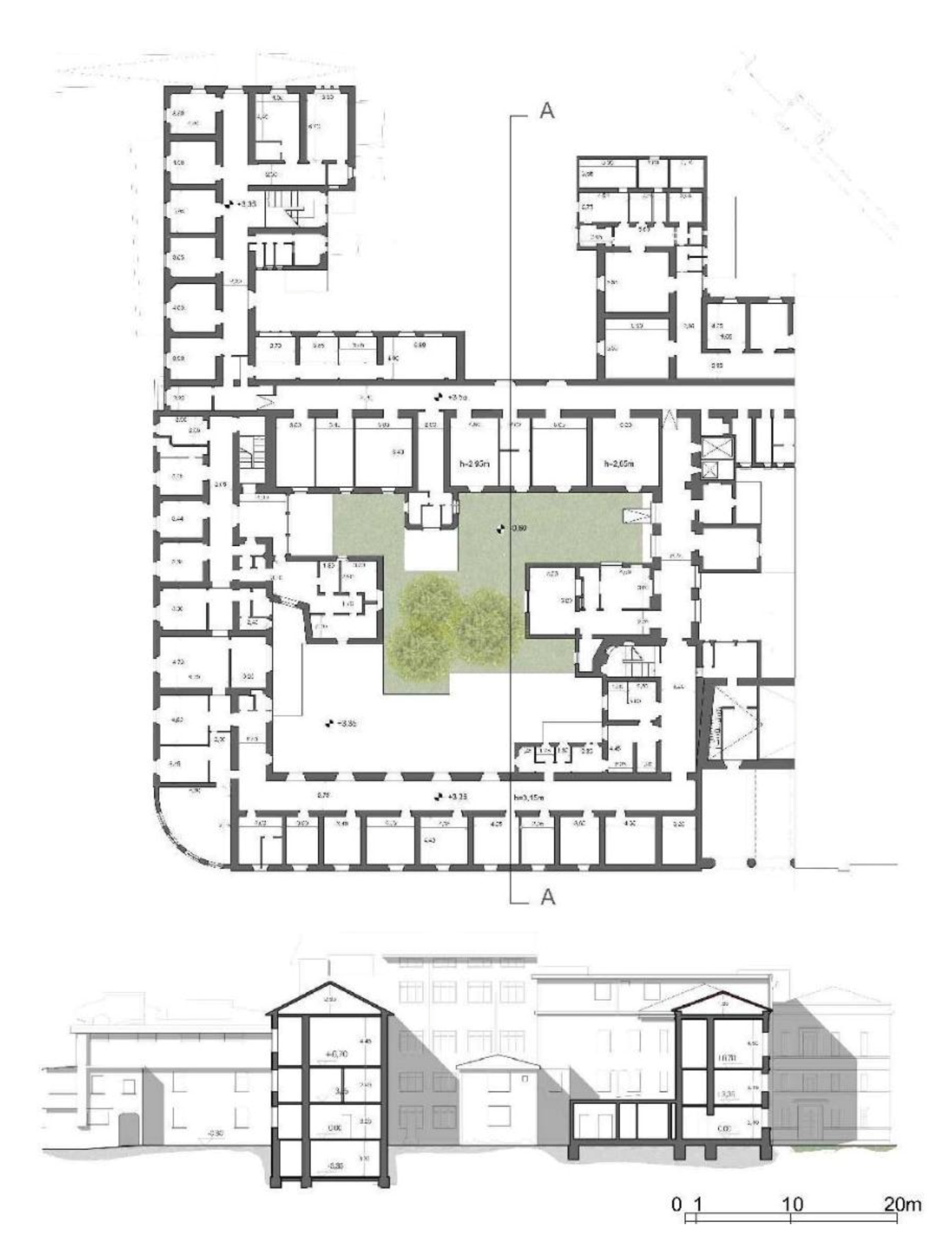
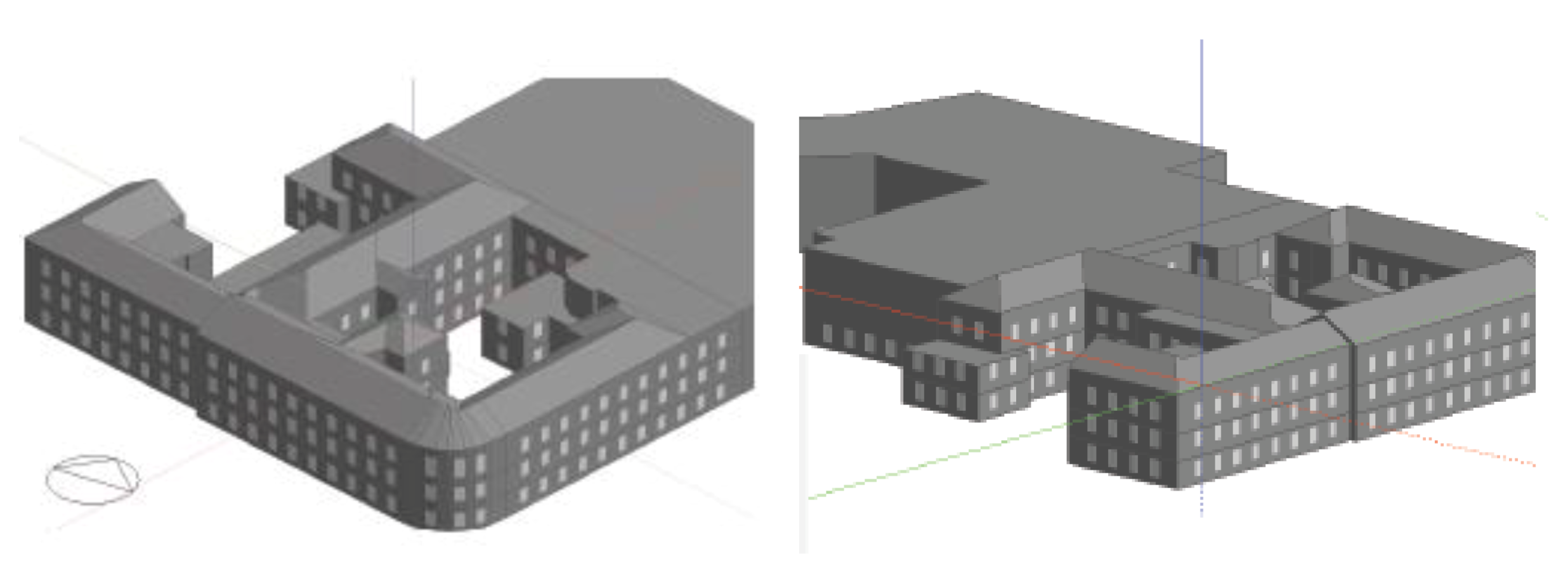
3. Stage 1, Steps 1 and 2: The Case Study and Surveys

The building under study has been empty since the late 1990s, and the structure has fallen into a state of disrepair, aggravated by the damage of the earthquake that struck the city in 2009. The building complex, owned by the University of L’Aquila, is part of a larger project that involves the re-development of the area adjacent to the former hospital with the goal of creating a new university center [31].
The building underwent numerous extensions and modifications over the years, some of which were the result of projects and others simply additions to meet functional needs (Figure 2). The evolution of the architectural complex since 1875 has been reconstructed through site inspections and historical sources (Figure 3). In 1931, following a period of inactivity, a project to extend the hospital resulted in the construction of new volumes and renovation of existing spaces. Over the years, up until 1983, the building complex continued to undergo continuous volume transformations that altered its original architectural aspect [32].
It is particularly interesting to note the evolution of construction technology in the extensions made over the years. Substantial differences were found in both vertical and horizontal closures, starting from the original nucleus–characterized by load-bearing masonry on uneven stone and floors with iron beams and brick hollow slabs or solid brick vaults, continuing with the extensions that took place in subsequent years. The work presented in this paper concerns the extension built between 1931–1939 to house operating rooms, chemistry laboratories, and the obstetrics department and school (Figure 4, Figure 5 and Figure 6).
Figure 4 shows the resulting extension: a single front aligned with the original position of the ancient church of Sant’Agnese, one of the few testimonies of the previous monastery, remodeled in the 700s following a devastating earthquake. The position of the church is thought to correspond to the right access at the front of the building, while the left access is that to the new extension. In this historical photo it is possible to recognize characteristic features of the Italian monumental architecture of the Fascist period: the front was in fact listed by the S.A.B.A.P. (superintendence of cultural heritage).
This portion of the building has a load-bearing stone masonry: it is a stone rubble work, framed in double course brick rows every 60 cm in height. The peculiarity of this masonry is the presence of reinforced concrete pillars inside the masonry, probably to increase its resistance in the areas of the wards that were once double in height. This construction technology adopted by the engineers, a co-existence of traditional masonry walls and concrete pillars, is innovative as it is one of the first examples of reinforced concrete structures in the territory of L’Aquila. Interestingly, the insertion of pillars into the mixed masonry was not permitted by legislation in that period [45]. The slabs are of two different types: a reinforced concrete slab and hollow block cast in place and a slab made of double T beams and brick hollow flat blocks with air chambers (Figure 7).

3.1. Ambiguous Constraints

Constraints on the architectural complex and, in particular, on the extension dating back to the 1930s are ambiguous: the former hospital is defined as ‘of Cultural Interest’ but ‘unverified’. However, its location within the historical city walls, its vicinity to the historical city center and its age mean that the building is considered a protected asset. Furthermore, it is testimony to the city’s past and has been extensively studied and described in numerous texts by illustrious historians and scholars [46,47,48,49,50,51,52,53,54,55,56,57].
This was taken into account during the design phase, especially when looking at the interventions to be carried out and their degree of invasiveness in the values/transformability map. After analyzing the building’s features of values, a degree of transformability was assigned to each structural and non-structural component. Features of historical, spatial, and cultural value were identified in the original volume whilst it was possible to establish which sections were simply superfluous additions.
One issue that came to light during this phase was the conservation of the facade in its openings/solid ratio as the historical plaster was found to be severely damaged. Whilst a particularly interesting feature of cultural and environmental value to be safeguarded and restored was the internal courtyard, especially in light of the future use of the structure as a University Pole as this space could act as an aggregation point. Lastly, the decorative values of the complex lay in the stone surrounds of the external portals.

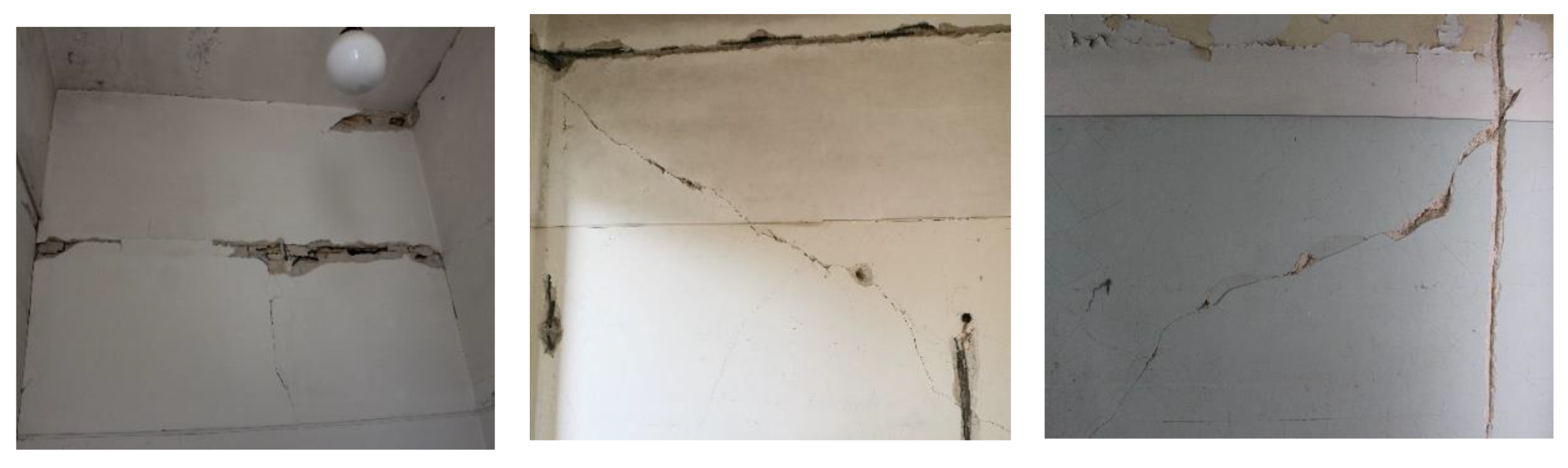
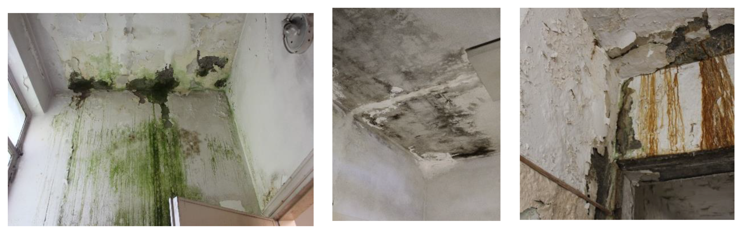
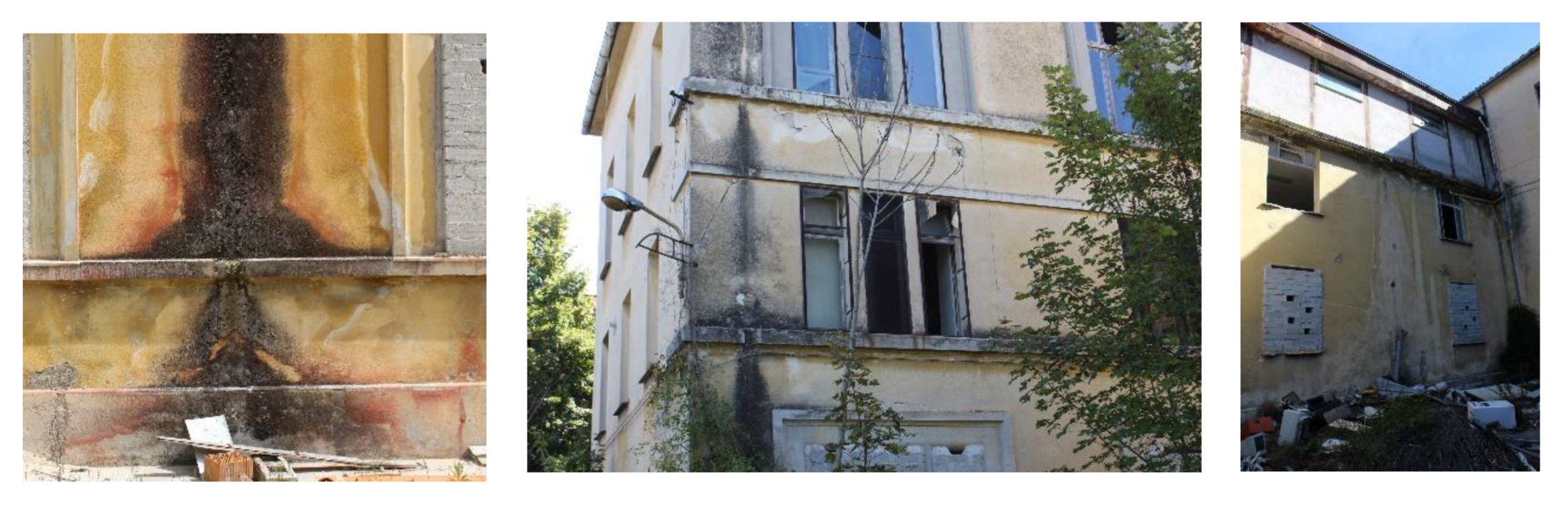
3.2. Damage Analysis

The damage analysis of a building, especially after a seismic event, is essential for assessing its structural state. The crack pattern of the interior and exterior of the building was carried out at a qualitative level for the evaluation of future consolidation interventions. The crack pattern was recorded over the floors of the building and on the elevations (including the extension of 1931–1939). It was possible to examine these thanks to the presence of scaffolding, installed after the earthquake to ensure the stability of the structure. Vertical structures in most cases had isolated or diffuse deep cracks and architrave lesions, while horizontal closures had ceiling-wall detachments and deep cracks, as shown in the Figure 8. On the elevations, there were no significant cracks but widespread lesions at the architraves.

3.3. Surface Degradation Analysis

The study of degradation is a fundamental in-situ analysis essential for any kind of building restoration.
The in-situ analysis revealed a severe state of deterioration. A mapping of the deterioration both internally and externally was carried out following the UNI 11182 for macroscopic degradation.
Internally, water was the primary cause of degradation in the form of humidity inside the masonry due to capillary rising, infiltration, and condensation, as shown in Figure 9.
Externally, stains from rising infiltration, oxidation of metal elements and high water content were found (Figure 10). Another phenomenon noted was the chromatic alteration from solar radiation and atmospheric pollutants.

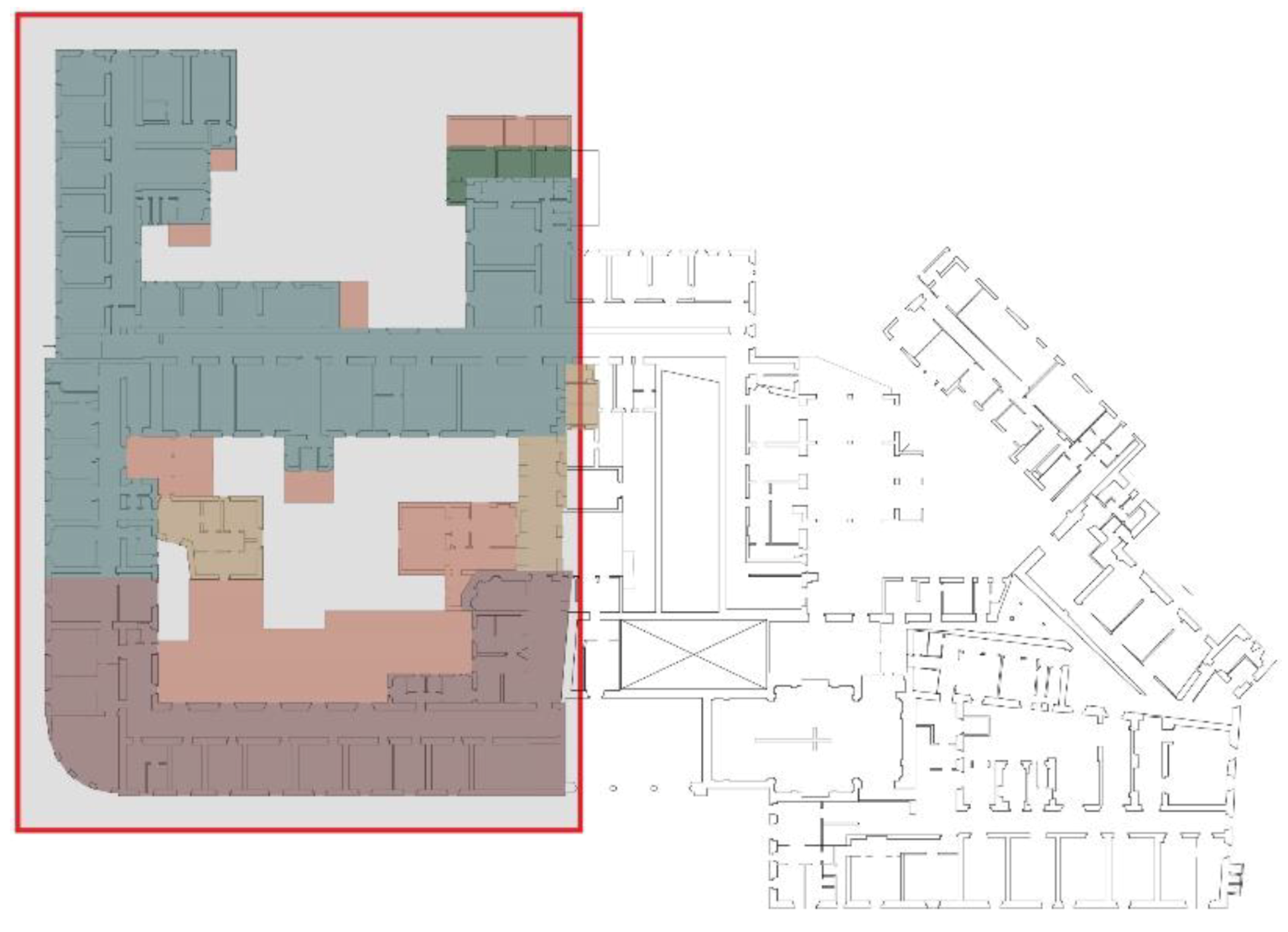
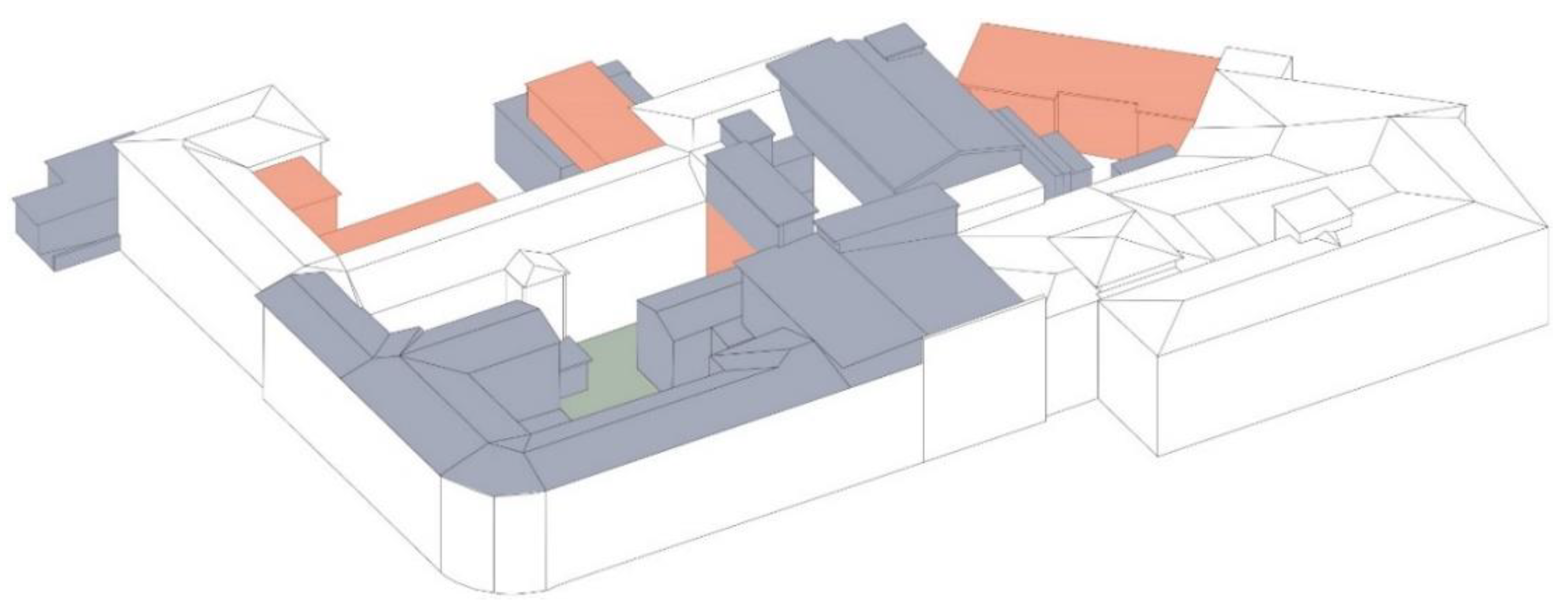
3.4. The Values/Transformability Map

The building’s varying features of value and the degree of transformability of its components were identified; these values were then assigned a value (high-medium-low), vertical connections were assigned construction values and some stone intrados, decorative values.
The transformability of both the envelope and horizontal/vertical connections was then calculated and the degree of transformability assigned on the map; for example, the east and south elevations are transformable but only with the respect to the openings of the facade, while floors have a high degree of transformability.
Cross-referencing the two analyses allowed for the identification of all the elements to be preserved during the project strategy phase (those with a high level in the map of values and a low level in the map of transformability) as well as all the elements with high transformability and no historical, environmental, decorative or constructive value that during the project strategy phase, could be subject to more invasive interventions or even demolition. The latter is the case for the extensions that took place between 1956 and 1983, which transformed the volume, without a project, integrating them into the existing building. In fact, during this time, new volumes were created for purely functional purposes, altering the design logic that underlies the building complex and distorting the architectural, typological, and structural aspects. All these superfetations and design incongruities are shown in Figure 11 and their demolition is planned for the next design step.

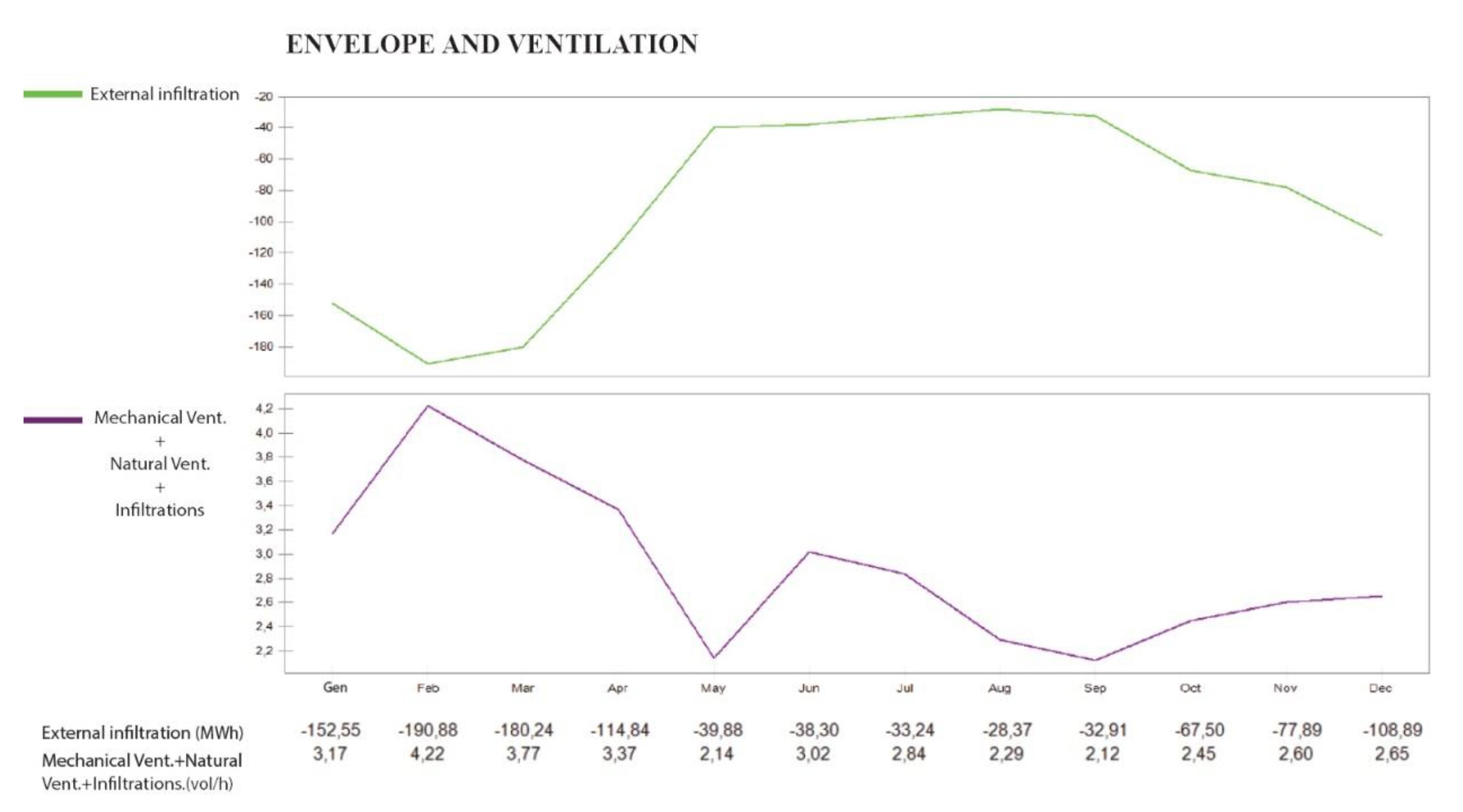
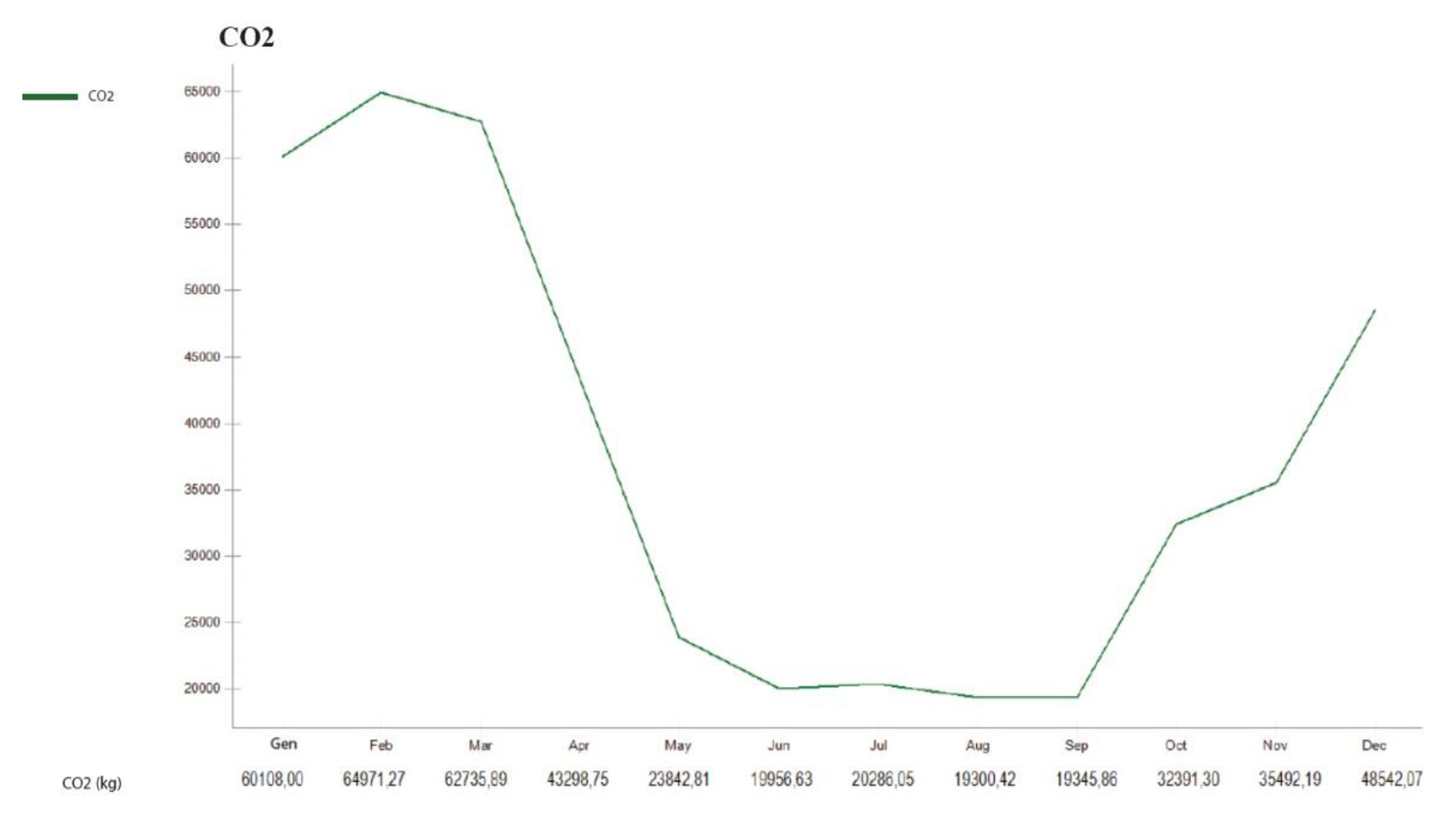
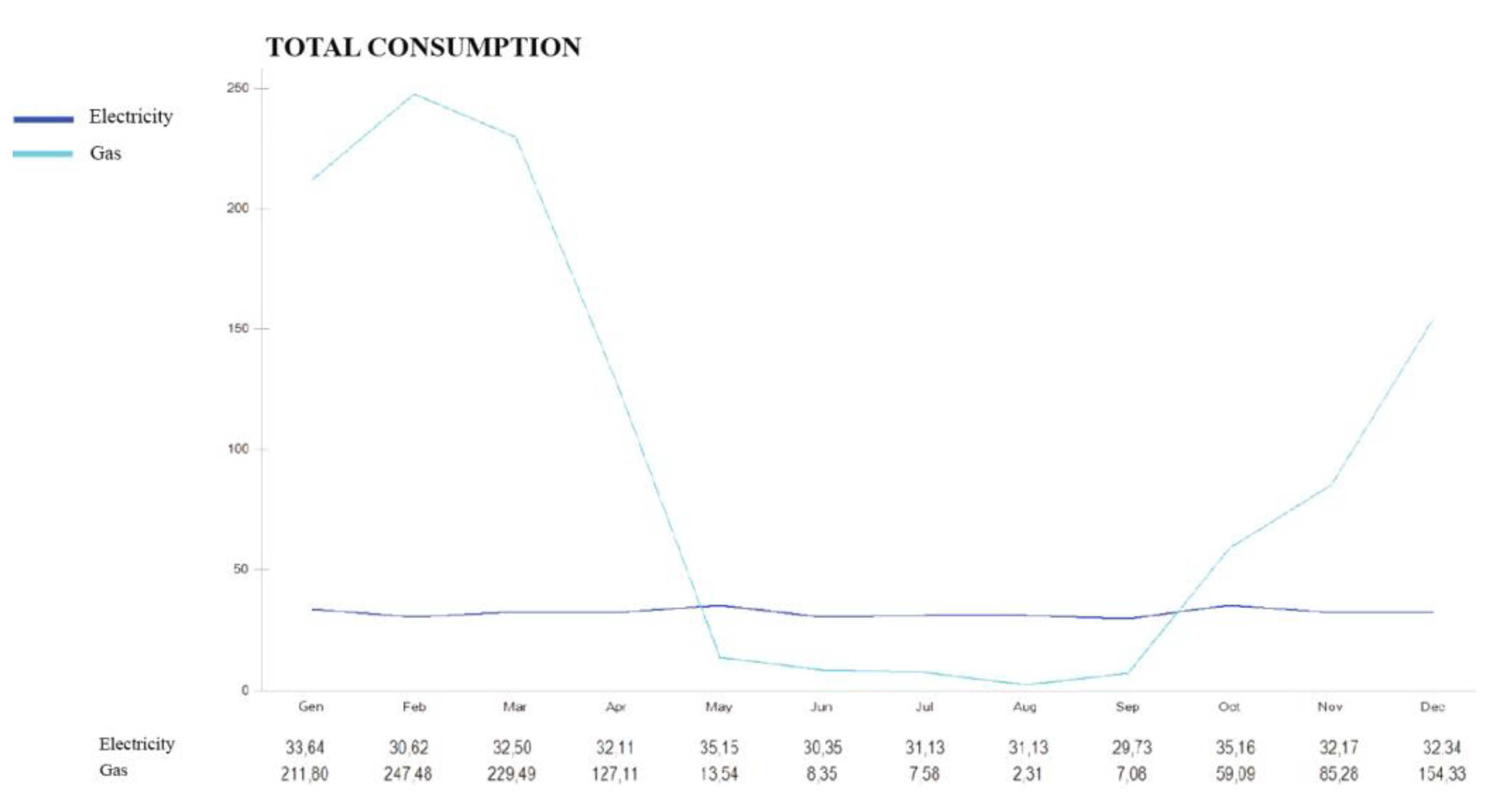
3.5. Energy Audit in the Current State

The energy diagnosis is of primary importance as it sheds light on the environmental performance of the building and its energy criticalities in its current state and for future configurations.
The envelope was of particular interest as the complex has no HVAC systems. The energy diagnosis was carried out with non-invasive techniques such as thermographic analysis and thermofluximeter analysis. The thermographic analyses carried out on the external elevations of the building confirmed the masonry construction and the presence of reinforced concrete pillars inside the masonry. The thermographic analyses also identified and located the problem of capillary ascent, which is a serious factor in the deterioration of internal and external walls [33].
The thermofluximeter analysis is a useful tool for energy diagnosis because it allows the designer to measure the thermal transmittance (U-value) of a building component quantitatively. The energy analysis of the actual state of a building is no longer entrusted to a transmittance value calculated through design data or by analogy with other structures but through a value measured on site. In the building studied, a suitable room was chosen for the test: a thermoflowmeter Text 434.2 was used, the monitoring lasted 72 hours in line with the ISO 9869 standard, and the recorded values were analyzed using Testo ComSoft Professional 4 software (4, Testo SE & Co. KGaA, Titisee-Neustadt, Germany). Using the arithmetic mean of the recorded numerical values, the transmittance value of the masonry was calculated as 1.817 W/m2K [33].
Once all the building data were acquired, a dynamic energy analysis was carried out using the Design Builder software. A dynamic simulation gives designers a more precise and realistic assessment of a building’s thermal behaviour compared to a stationary analysis. In a dynamic simulation, all the variable factors that affect the behaviour of a building and the resulting energy balance are considered: factors such as the thermal inertia of the envelope, internal contributions, solar contributions and the change in external climatic conditions. Furthermore, the behaviour of the building is simulated hour by hour in order to provide an accurate, overall picture.
The weather data for Campobasso, which has similar climatic conditions to L’Aquila, was used for the construction of the model. The model was drawn using software (Figure 12) and the data for the simulation described in Table 1 entered. The destination of use was set to "university classroom", in light of the future plans for the building.
The results of the simulations are shown in Figure 13, Figure 14 and Figure 15, and data on the envelope, ventilation, comfort, system loads, CO2 production, and total electricity and gas consumption under current conditions but with future use are shown. Significant values of CO2 consumption are evident over the winter months.

4. Step 3. The Project-Strategy Map

After analyses of the current state of the building: architectural, energetic (through the simulation in dynamic regime) and structural (carrying out local checks on the floor masonry and calculating the centre of mass and the barycentre of rigidity), the results were combined to produce a critical and global evaluation of the building. In the project strategy map, three macro-categories of criticality were identified for the current state of the building: spatial-functional, performance and structural (Figure 16). The spatial-functional criticality included all the superfluous additions identified through the values/transformability map, and the humidity, found when analyzing the state of degradation. Critical performance issues included the presence of thermal bridges due to the pillars in the masonry and to floor curbs; capillary rise of water; high production of CO2; high global consumption undetected through the dynamic simulation with Design Builder software and the presence of infiltrations, clear in the analysis of the degradation. Structural criticalities were identified on the floors and walls, besides the presence of eccentricity between the centre of gravity of the masses and the barycentre of the rigidities creating torque effects on the resistant elements.
Compatible retrofit interventions were drawn up by cross-checking structural, energetic and spatial-functional criticalities with transformability and architectural values.

4.1. Highlighting Compatible Strategies for Seismic Retrofitting

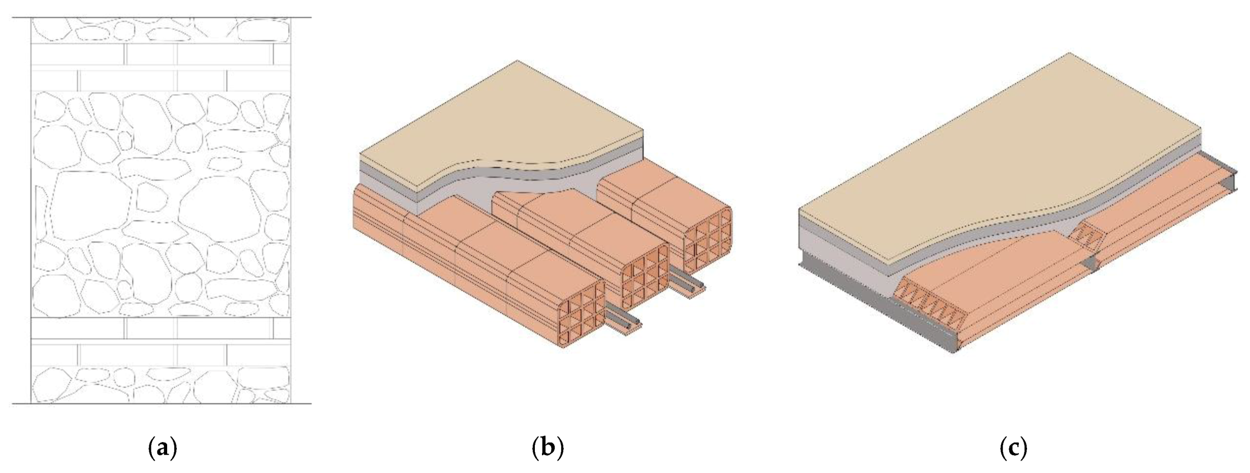
4.1.1. Interventions on Slabs

The compatible design strategies for the seismic retrofit envisage either the consolidation of the slabs or their demolition and refurbishment, depending on the value and the degree of transformability corresponding to the specific intervention objective. Hypothetical interventions were studied for both situations, and evaluated according to their degree of reversibility and invasiveness for consolidation interventions, and according to the degree of reversibility and compatibility for renovation interventions, summarised in Table 2.
The first option for consolidation was a reinforcement system with GFRP (glass fiber reinforced polymer) nets and bars, which, combined with mortars of different types, create reinforced slabs that improve the distribution of horizontal seismic forces and allow the distribution of loads acting on the floor itself. The second option for a consolidation intervention was a reinforcement system with specific connectors and electrowelded mesh, useful in case of brick slabs.
Three options were also considered for the demolition and renovation of the floors. The first solution was the construction of a new brick slab, using the same technology as the old slab, inserting a slab with electrowelded mesh. The second option was the construction of a one-way or two-way EPS (sintered expanded polystyrene) slab therefore using a self-supporting formwork, with high performance thanks to the structural collaboration between sintered expanded polystyrene and metal profiles. The third option was the construction of a steel floor using profiles and corrugated sheet metal, reinforced screed casting with electrowelded mesh.

4.1.2. Stone Masonry

For masonry with a medium/high value and a medium/low degree of transformability, the compatible project strategy was that of consolidation, therefore interventions aimed at increasing the characteristics of the walls-in particular the resistance to vertical loads-and at re-positioning the barycentre of stiffness. All the hypotheses proposed, summarised in Table 3, were classified according to the degree of invasiveness and the degree of reversibility. Given the state of damage of the building, invasive structural interventions had to be evaluated although they would not allow for the preservation of all the original elements such as the historical external plaster.
Interventions considered were: injections of binder mixtures, an operation that restores or improves the mechanical characteristics of the wall face; the use of reinforced plaster, a layer of cement-based material, reinforced with wire mesh and bound to the masonry with steel tie rods; armed injections in holes inside the masonry; the CAM system (active artifact seams), a reinforced seam of the masonry with stainless steel strips arranged horizontally and vertically, passing through the wall thickness and sealed back on themselves; and lastly, applying FPR(fiber reinforced polymer) foils, fabrics or nets on the structural elements of the construction. An intervention compatible with all the options described above is the hooping of the openings whilst the last option studied was a less usual intervention: the insertion of new pillars inside the existing masonry. As mentioned previously, there are parts of the building with reinforced concrete pillars, so this would give a degree of uniformity although it is a very invasive intervention.

4.2. Step 4. Compatible Strategies for Energy Retrofitting

4.2.1. Slabs

For compatible energy interventions, the project strategy adopted was that of integration. Compliant energy solutions were studied for both existing slabs being consolidated and the substitution of the existing ones, shown in Table 4. Since this is an energy improvement, there was no obligation to respect the minimum energy performance requirements imposed by the DM 26 June 2015, but these values are considered a yardstick for choosing the most valid intervention hypotheses. The city of L’Aquila is located in climate zone E and, for vertical closures, the limit value for thermal transmittance is 0.30 W/m2K.
For the intervention on existing slabs, it is essential to know the transmittance value of the element, equal to 1625 W/m2K for reinforced concrete slabs and hollow block cast in place and 1383 W/m2K for slabs made of double T beams and brick hollow flat blocks. For both types, four intervention options were studied: using different insulating panels-cork, EPS, rock wool and Aerogel. The transmittance value reached, the necessary thickness, the risk of condensation and the cost were calculated for each configuration. Taking as an example the concrete-brick slab, the first coating proposed was a 10 cm thick insulating panel in cork of vegetable origin, with which a transmittance value of 0.343 W/m2K was achieved without the risk of condensation, at a cost of between 20–40 €/m2. For the second option, an 8 cm thick EPS panel of synthetic origin was chosen: this gave a transmittance value of 0.272 W/m2K without condensation risk, at a cost of 8–15 €/m2. Inserting a 10 cm insulating panel of rock wool of mineral origin, the transmittance value was 0.297 W/m2K without causing condensation and at a cost of 10–19 €/ m2. The last configuration tested was an Aerogel panel of synthetic origin which had a transmittance value of 0.264 W/m2K.
Energy solutions were studied for each option. For the renovation of the slab and the construction of a concrete-brick slab, the same solutions explained above were applied. For the bi-directional EPS floor (the second structural solution shown) three configurations were studied. By choosing a thickness of 4 cm for the sub-joist, the transmittance value was 0.41 W/m2K. In order to achieve an even lower transmittance value, the thickness of the sub-frame can be increased: 6 cm gives a transmittance value of 0.30 W/m2K, or a layer of insulation can be inserted: with an aerogel panel of 2 cm the transmittance value drops to 0.28 W/m2K. For a new steel floor, three solutions were studied: the insertion of a stone wool panel, one of EPS and one of Aerogel. The best solution was the Aerogel panel which, with a thickness of 5 cm, gave a transmittance value of 0.27 W/m2K, unlike the other panels which, even with greater thickness, were not able to reach this level of performance.

4.2.2. Ground Slab

Interventions on the floor against the ground are necessary due to capillary ascent. This is a slab on a gravel crawl space and beaten concrete floor with a calculated transmittance value of 1.47 W/m2K. The energy intervention chosen was that of integration and therefore the insulation at the extrados of the slab. Three hypotheses were studied: insulation with an EPS panel, an aerogel panel and through a crawl space with expanded clay (Table 5). With the 10 cm thick EPS panel, a transmittance value of 0.31 W/m2K was achieved, but with a risk of condensation and a cost of 8–15€/m2. With the second solution, the 5-cm thick aerogel panel achieved a U value of 0.26 W/m2K, without risk of condensation but at a higher cost. The last solution was a 30 cm crawl space of clay, reaching a value of 0.32 W/m2K, without the risk of condensation at a cost of 30–40 €/m2.

4.2.3. Roof

The current roof is made of non-insulated wood with a calculated transmittance value of 2.70 W/m2K. Also, in this case, the solution chosen was integration: inserting the insulation under the covering. The solutions studied were the three most compatible with the original construction: cork, aerogel and rock wool panels. Since thickness was not an issue, we found that a 12 cm thick rock wool panel of mineral origin, achieved a transmittance value of 0.24 W/m2K without the risk of condensation and at a much lower cost than a 6 cm aerogel panel with a transmittance value of 0.28 W/m2K, whilst a cork panel of 12 cm did not achieve an acceptable transmittance value.

4.2.4. Stone Masonry

Thanks to thermoflowmetric analysis, energy interventions on the masonry were based on a transmittance value measured in-situ: 1.82 W/m2K. Also, in this case, the values imposed by Ministerial Decree 26 June 2015 which provide transmittance values for opaque vertical closures of 0.30 W/m2K in the climatic zone E were used as milestones. The intervention design strategies were: the insulation of the external wall, of both the internal and external wall, and of just the internal wall only. External insulation has the advantage of reducing the effect of thermal bridges caused by the presence of pillars but the disadvantage of altering the aesthetic and technological features of the facades. Internal insulation has the disadvantage of reducing the internal volume in case of excessive thickness and creating condensation problems, but it is necessary in cases where the facade of a building is subject to constraints. The three insulation methods were studied using five different types of insulation, namely EPS, rock wool, Aerogel, vacuum panels VIP (vacuum insulation panel), and thermal plaster, and evaluated according to transmittance, condensation risk, thickness, and cost (Table 6).
The internal insulation in vacuum panels VIP was chosen because, with minimum thickness, a low thermal transmittance value is reached, without risk of condensation. Internal and external insulation with aerogel panels was chosen because, in addition to the guarantee of low transmittance value, aerogel panels prevent distortion of the external facade thanks to their minimum thickness.

4.2.5. Windows

The energy intervention strategy for windows was the replacement of unsuitable windows and the recovery of valuable elements. The transmittance value of the current windows is 3.10 W/m2K as they are wooden windows with single-glazed glass and in some cases with damaged or missing panes. The DM 26 June 2015 sets out a thermal transmittance limit value of 1.80 W/m2K in climate zone E. Four solutions were evaluated: a double-glazed wooden frame with a transmittance value of 2.30 W/m2K but with a risk of condensation; a double-glazed wooden frame with low-emission coating that removes the risk of condensation with a transmittance value of 1.30 W/m2K; a wooden frame with triple-glazed glass and a transmittance value of 1.00 W/m2K, and the last, a triple-glazed frame with low-emission coating with a U-value of 0.70 W/m2K.

5. Results

For each construction element of the building envelope, differing solutions were studied and evaluated. Structurally, they were evaluated on the basis of the current damaged state of the building. The significant structural damage meant that more invasive energy solutions could be taken into consideration. This does not mean that the features of value will be lost: they will be preserved wherever possible, maintaining, for example, the openings/solid ratio of the façade and reconditioning the original geometry of the building.
Energy compatible interventions were chosen from those studied for each building element of the casing based on a critical cost-benefit assessment. For the masonry, internal and external aerogel insulation (which limits the thickness of the external panel) and internal insulation with VIP vacuum panels (with more performance and no condensation) were chosen. For the slabs, the solutions with EPS and Aerogel panels, that guarantee better performance with lower thickness, were chosen. For the other components, unique solutions were chosen, such as the wooden frame with double-glazing and low emissivity coating, the insulation of the floor against the ground with Aerogel panels, and for the roof, insulation with rock wool panels.

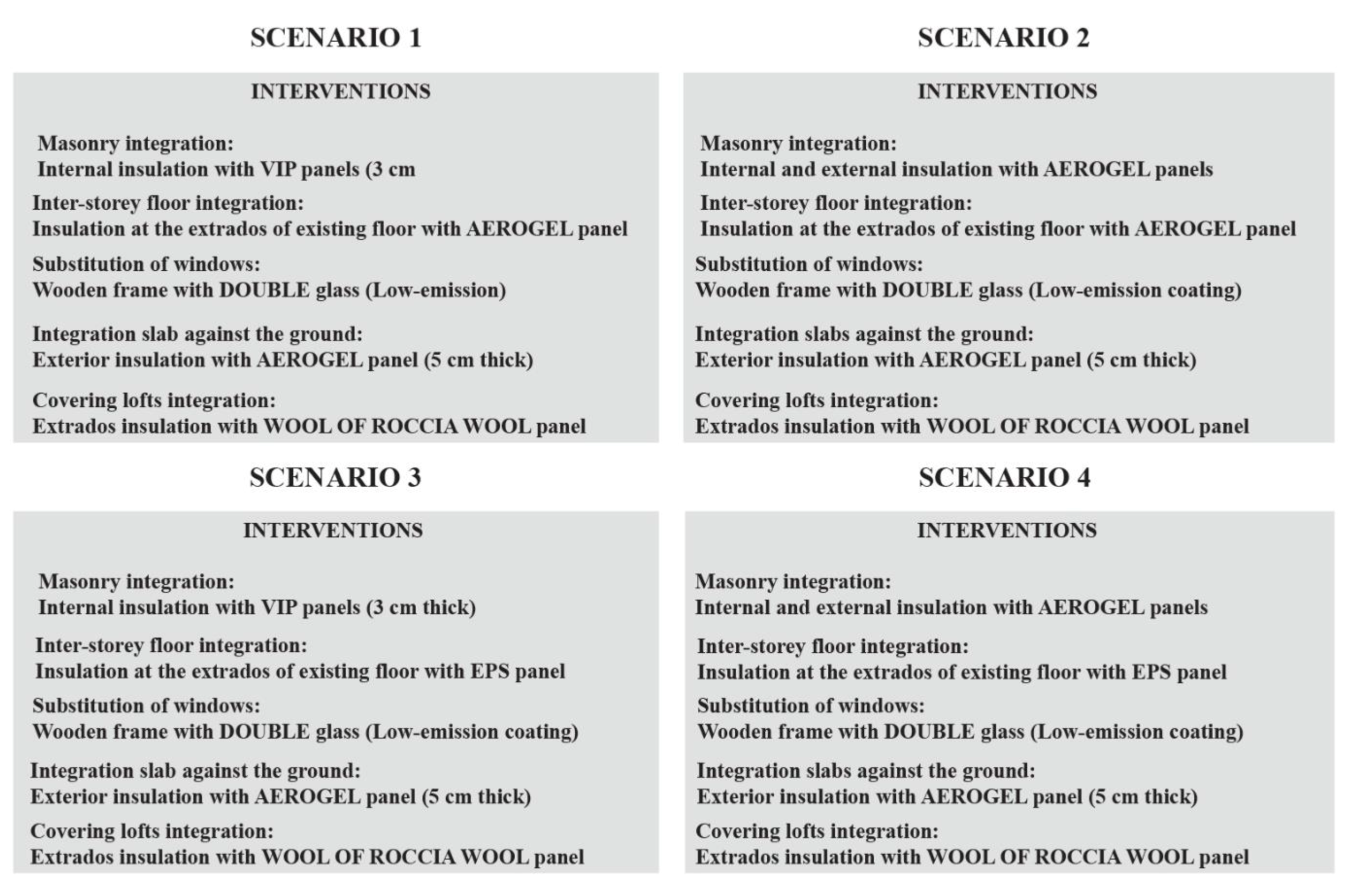
5.1. Step 5. Indentifying Compatible Scenarios

Four scenarios were defined by combining the solutions chosen for each construction component, as shown in Figure 17.

5.2. Step 6 and 7. Modelling and Evaluating Different Scenarios

Using the Design Builder software, the interventions used in the four scenarios were inserted into the model of the current state of the building and through static simulations, improvements in energy performance were evaluated, calculating the percentages of savings in terms of consumption and CO2 production, and the total cost of the interventions.
The input data for each scenario included in the model are shown in Table 7, which highlights common features between the scenarios as well as differing data according to the interventions predicted for each scenario.
Table 8 shows the results of the simulations of the four scenarios and the decrease in total consumption and CO2 production.

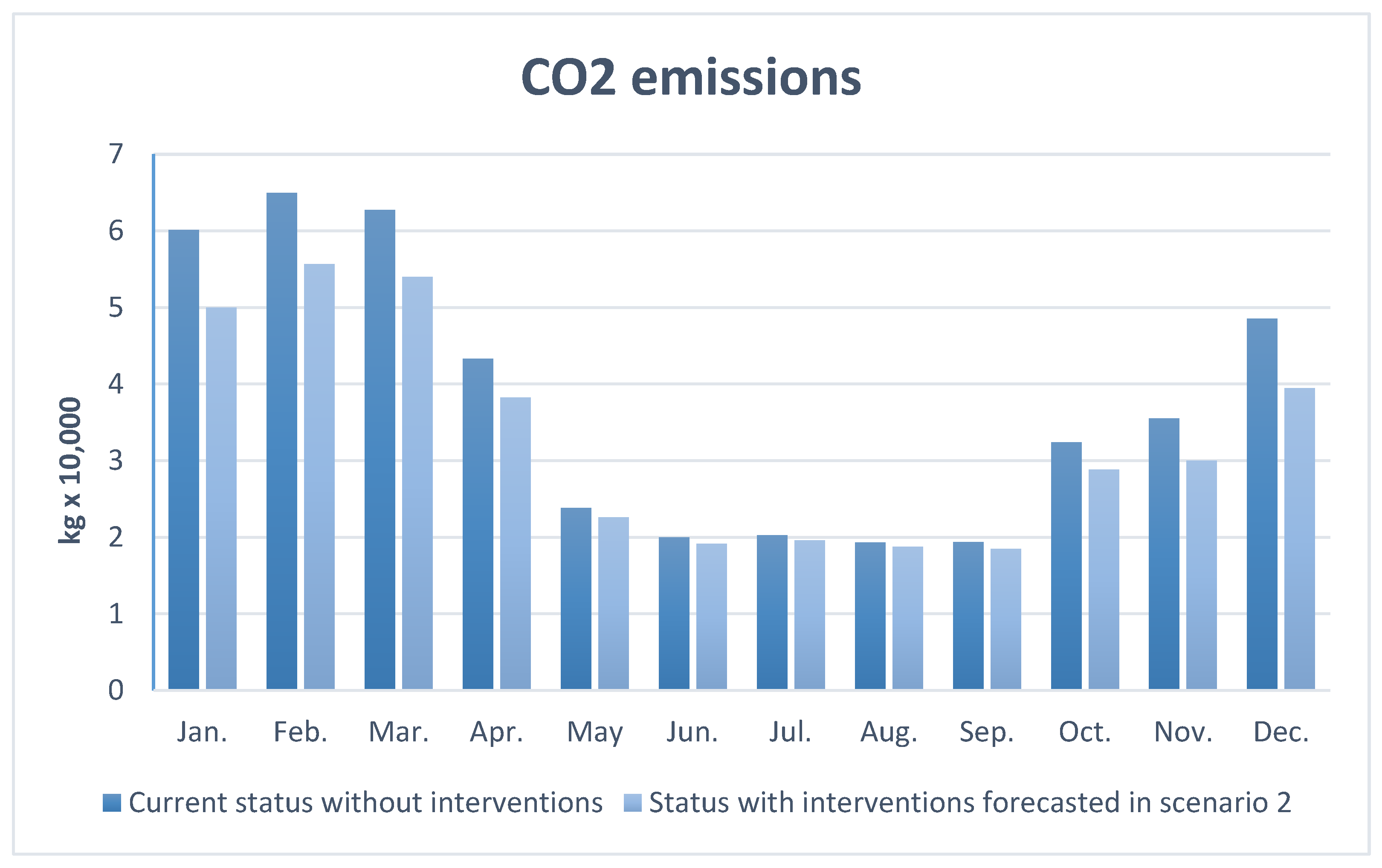
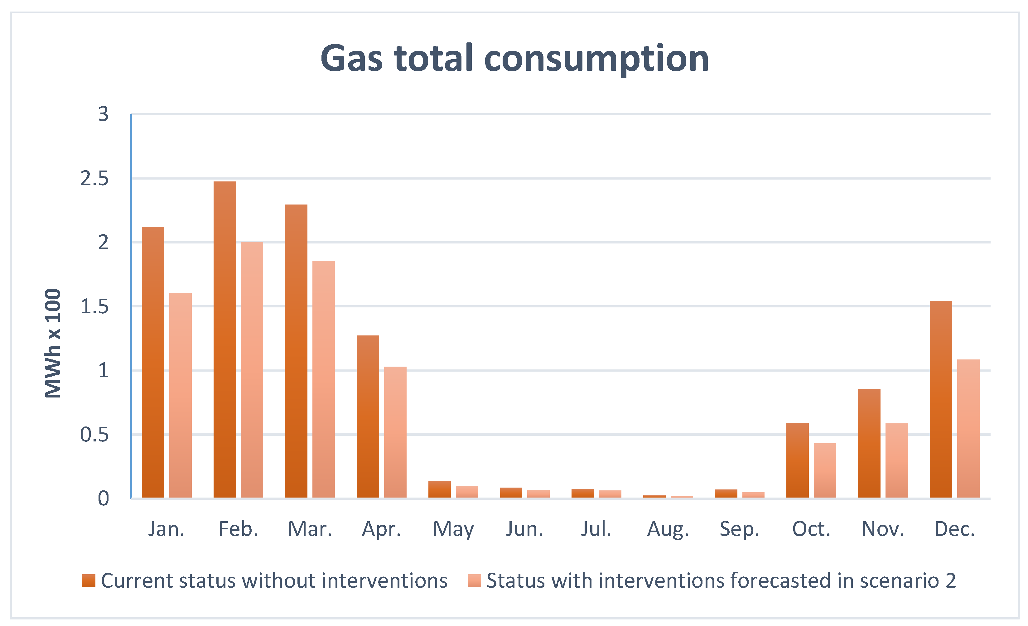
5.3. Step 8. Dynamic Simulation Results

The scenario chosen after these assessments was the second scenario with internal and external insulation of the masonry with aerogel panels, insulation of the slab with aerogel panels, double glazed windows and low-emission cladding, insulation of the slab against the ground with aerogel panels and stone wool panel roof insulation. It is the best scenario in terms of energy performance and resolves the problem of thermal bridges.
A dynamic simulation was also carried out for this scenario using the input data in Table 7. The results obtained on CO2 production and total electricity and gas consumption are shown in Figure 18 and Figure 19.

6. Discussion

The performance improvement obtained with the application of the methodology described in this paper can be clearly seen and interpreted in the light of a comparison between the simulation results of the current state and those of the chosen scenario shown in Section 5.
From the graphs below, the significant fall in the main parameters involved in the environmental management of the building sector are particularly evident; in particular the 13.78% fall in CO2 and the 24.64% decrease of total gas consumed.
In order to provide a complete picture, the data have been summarized in Figure 18 and Figure 19 which show the monthly variations.
Although the objective of improving environmental performance with a view to compatibility with the restoration of the building and protection of its values has been achieved and demonstrated, the most relevant results of this work consists in the definition of a simple and easily applicable -methodology for a profitable use of dynamic simulations in application to cultural heritage. In this methodology, energy modeling and dynamic simulations are used as a forecasting tool for the effectiveness of the energy improvement interventions hypothesized. This tool follows the design process from the earliest stages and the fact-finding investigations. The model is then updated according to the results of the preliminary analyses and as intervention strategies for the redevelopment of the building are outlined. In the final analysis, it is precisely the dynamic simulation tool that is able to synthetize all the information and project data collected from the first design steps that can guide the designer towards the most appropriate choice in relation to the case study, the client and user needs.
Importantly, the different hypothetical scenarios all comply with the objectives of protection and enhancement. Therefore, each of them (as well as other solutions not described here) can be considered and implemented safely without compromising coherence or environmental needs. The optimization of the process therefore lies in the identification of compatible scenarios but the choice of the “optimal solution”, is conditioned by subjective needs, which do not, however, compromise the design quality ensured by the application of the methodology itself. The economic availability and investment capacity of the client can also sway the choice towards one scenario rather than another, but again, they may be safe in the knowledge of achieving adequate seismic and energy performance improvements and contributing to the protection of the architectural heritage and to its enhancement.

7. Conclusions

This research focuses on the optimization of performance that can be achieved in historical structures during retrofitting through a pre-established process. All the steps of this process have been described in order to make the whole procedure replicable, with the aim of establishing a best practice methodology that can be used for the future restoration and enhancement of heritage buildings and monuments. We believe that, in this field, the “process” is just as important as the intervention itself.
We presented a building severely damaged by an earthquake, for which massive structural improvement measures are necessary. However, most historic buildings even if they have not been subjected to seismic events, have structural vulnerabilities that can be resolved during an energy retrofit, since the two types of intervention have many overlapping phases. This is recognized in a recent Decree, 19 May 2020 passed by the Italian government to encourage economic recovery following the Covid-19 emergency, through economic assistance for seismic and environmentally related building renovations. Despite national and international regulations and the great steps taken by scientific research, literature, and professional practice, a methodology that can unify aspects related to restoration, structural safety and energy efficiency is needed. This paper shows how restoration, structural and energy choices communicate and influence each other: in the case study presented it was possible to opt for invasive but better performing energy interventions as a result of the need for structural interventions. From an environmental point of view, the different scenarios and the critical evaluation of the appropriate solution through energy modelling and simulations guarantee a choice of effective interventions, compatible and consistent with restoration aims, static safety and energy saving. The use of the Design Builder software allows a rapid visualization of the envelope’s thermal characteristics but modeling in an HBIM environment would be more desirable in future.

Author Contributions

Conceptualization, M.D.V. and P.D.B.; methodology, M.D.V.; software, M.D.V. and G.M.; validation, M.D.V., P.D.B., and G.M.; formal analysis, M.D.V. and G.M.; investigation, M.D.V and G.M.; data curation, G.M.; writing—original draft preparation, M.D.V. (Section 1, Section 2, Section 6 and Section 7) and G.M. (Section 3, Section 4 and Section 5); review and editing, M.D.V. (1, 2, 6 and 7) and G.M. (3, 4 and 5); supervision, P.D.B. and M.D.V.; project administration, P.D.B. and M.D.V. All authors have read and agreed to the published version of the manuscript.

Funding

This research received no external funding.

Acknowledgments

The work presented in this paper was developed starting from an in-depth study on the building as a whole by the engineer Luisa Capannolo for her thesis. This contribution represents the first application of the methodology hypothesized in the research project on the guidelines drafting for the renovation of the former S. Salvatore Hospital.

Conflicts of Interest

The authors declare no conflict of interest.

References

  1. Change, IPCC Climate. Buildings, Climate Change 2014: Mitigation of Climate Change. Contribution of Working Group III to the Fifth Assessment Report of the Intergovernmental Panel on Climate Change; The Intergovernmental Panel on Climate Change (IPCC): Geneva, Switzerland, 2014. [Google Scholar]
  2. Available online: http://www.bp.com/ (accessed on 3 April 2020).
  3. Lavagna, M.; Baldassarri, C.; Campioli, A.; Dalla Valle, S.G.A.; Castellani, V.; Sala, S. Benchmarks for environmental impact of housing in Europe: Definition of archetypes and LCA of the residential building stock. Build. Environ. 2018, 145, 260–275. [Google Scholar] [CrossRef]
  4. Economidou, M.; Atanasiu, B.; Despret, C.; Maio, J.; Nolte, I.; Rapf, O. Europe’s Buildings under the Microscope: A Country-By-Country Review of the Energy Performance of Buildings; Building Performance Institute Europe (BPIE): Brussels, Belgium, 2011; p. 43. ISBN 9789491143014. [Google Scholar]
  5. Koukkari, H.; Brangança, L. Review on the European strategies for energy-efficient buildings. Int. J. Sustain. Build Technol. Urban Dev. 2012, 2, 87–99. [Google Scholar] [CrossRef]
  6. The European parliament and the Council of the European Union. Directive 2010/31/EU of the European Parliament and of the Council on the Energy Performance of Buildings, EPBD (Energy Performance of Buildings Directive); The European parliament and the Council of the European Union: Brussels, Belgium, 2010. [Google Scholar]
  7. Available online: https://ec.europa.eu/energy/topics/energy-efficiency/energy-efficient-buildings/energy-performance-buildings-directive_en (accessed on 3 April 2020).
  8. Costanzo, S.; Cusumano, A.; Giaconia, C.; Giaconia, G. Preservation of the artistic heritage within the seat of the Chancellorship of the University of Palermo: A proposal on a methodology regarding an environmental investigation according to Italian Standards. Build. Environ. 2006, 41, 1847–1859. [Google Scholar] [CrossRef]
  9. Berg, F.; Flyen, A.C.; Godbolt, A.L.; Broström, T. User-driven energy efficiency in historic buildings: A review. J. Cult. Herit. 2017, 28, 188–195. [Google Scholar] [CrossRef] [Green Version]
  10. Magrini, A.; Franco, G. The energy performance improvement of historic buildings and their environmental sustainability assessment. J. Cult. Herit. 2016, 21, 834–841. [Google Scholar] [CrossRef]
  11. Pigliautile, I.; Castaldo, V.L.; Makaremi, N.; Pisello, A.L.; Cabeza, L.F.; Cotana, F. On an innovative approach for microclimate enhancement and retrofit of historic buildings and artworks preservation by means of innovative thin envelope materials. J. Cult. Herit. 2019, 36, 222–231. [Google Scholar] [CrossRef] [Green Version]
  12. ICOMOS/ISCARSAH Committee. Recommendations for the Analysis, Conservation and Structural Restoration of Architectural Heritage; International Council on Monuments and Sites: Paris, France, 2005. [Google Scholar]
  13. International Council on Monuments and Sites. International charter for the conservation and restoration of monuments and sites (The Venice Charter). In Proceedings of the IInd International Congress of Architects and Technicians of Historic, Venice, Italy, 25–31 May 1964. [Google Scholar]
  14. Comite Europeen de Normalisation (CEN). Conservation of Cultural Heritage e Guidelines for Improving the Energy Performance of Historic Buildings; SS-EN-16883; Comite Europeen de Normalisation (CEN): Brussels, Belgium, 2017. [Google Scholar]
  15. Webb, A.L. Energy retrofits in historic and traditional buildings: A review of problems and methods. Renew. Sustain. Energy Rev. 2017, 77, 748–759. [Google Scholar] [CrossRef]
  16. Galatioto, A.; Ciulla, G.; Ricciu, R. An overview of energy retrofit actions feasibility on Italian historical buildings. Energy 2017, 137, 991–1000. [Google Scholar] [CrossRef]
  17. Boarin, P.; Guglielmino, D.; Pisello, A.L.; Cotana, F. Sustainability assessment of historic buildings: Lesson learnt from an Italian case study through LEED® rating system. Energy Procedia 2014, 61, 1029–1032. [Google Scholar] [CrossRef] [Green Version]
  18. Napoli, G.; Gabrielli, L.; Barbaro, S. The efficiency of the incentives for the public buildings energy retrofit. The case of the Italian Regions of the “Objective Convergence”. Valori Valutazioni 2017, 18, 25–39. [Google Scholar]
  19. Di Pilla, L.; Desogus, G.; Mura, S.; Ricciu, R.; Di Francesco, M. Optimizing the dis-tribution of Italian building energy retrofit incentives with Linear Programming. Energy Build. 2016, 112, 21–27. [Google Scholar] [CrossRef]
  20. Galatioto, A.; Ricciu, R.; Salem, T.; Kinab, E. Energy and economic analysis on retrofit actions for Italian public historic buildings. Energy 2019, 176, 58–66. [Google Scholar] [CrossRef]
  21. Ascione, F.; De Rossi, F.; Vanoli, G.P. Energy retrofit of historical buildings: Theoretical and experimental investigations for the modelling of reliable performance scenarios. Energy Build. 2011, 43, 1925–1936. [Google Scholar] [CrossRef]
  22. Cornaro, C.; Puggioni, V.A.; Strollo, R.M. Dynamic simulation and on-site measurements for energy retrofit of complex historic buildings: Villa Mondragone case study. J. Build. Eng. 2016, 6, 17–28. [Google Scholar] [CrossRef]
  23. Ciulla, G.; Galatioto, A.; Ricciu, R. Energy and economic analysis and feasibility of retrofit actions in Italian residential historical buildings. Energy Build. 2016, 128, 649–659. [Google Scholar] [CrossRef]
  24. Filippi, M. Remarks on the green retrofitting of historic buildings in Italy. Energy Build. 2015, 95, 15–22. [Google Scholar] [CrossRef]
  25. Evangelisti, L.; Guattari, C.; Gori, P. Energy retrofit strategies for residential building envelopes: An Italian case study of an early-50s building. Sustainability 2015, 7, 10445–10460. [Google Scholar] [CrossRef] [Green Version]
  26. Ma, Z.; Cooper, P.; Daly, D.; Ledo, L. Existing building retrofits: Methodology and state-of-the-art. Energy Build. 2012, 55, 889–902. [Google Scholar] [CrossRef]
  27. Roberti, F.; Oberegger, U.F.; Lucchi, E.; Troi, A. Energy retrofit and conservation of a historic building using multi-objective optimization and an analytic hierarchy process. Energy Build. 2017, 138, 1–10. [Google Scholar] [CrossRef]
  28. Pisello, A.L.; Petrozzi, A.; Castaldo, V.L.; Cotana, F. On an innovative integrated technique for energy refurbishment of historical buildings: Thermal-energy, economic and environmental analysis of a case study. Appl. Energy 2016, 162, 1313–1322. [Google Scholar] [CrossRef]
  29. Gabrielli, L.; Ruggeri, A.G. Developing a model for energy retrofit in large building portfolios: Energy assessment, optimization and uncertainty. Energy Build. 2019, 202, 109356. [Google Scholar] [CrossRef]
  30. Available online: https://whc.unesco.org/en/list/ (accessed on 30 March 2020).
  31. Bartolomucci, C.; Giancola, F.; Capannolo, L.; De Vita, M.; Laurini, E.; Marchionni, C.; (University of L’Aquila, DICEAA & National Research Council, ITC, L’Aquila, Italy). Studio di Fattibilità per il Progetto di un Polo Universitario nell’ex Ospedale San Salvatore. Feasibility Study; Scientific Contributor De Berardinis, P.. Personal communication, 2017. [Google Scholar]
  32. De Berardinis, P.; Bartolomucci, C.; Capannolo, L.; De Vita, M.; Laurini, E.; Marchionni, C. Instruments for Assessing Historical Built Environments in Emergency Contexts: Non-Destructive Techniques for Sustainable Recovery. Buildings 2018, 8, 27. [Google Scholar] [CrossRef] [Green Version]
  33. De Vita, M.; Massari, G.; De Berardinis, P.; Palmero Iglesias, L. Non destructive surveys for the protection of cultural heritage: Restoration in a post earthquake context. SCIRES-IT Sci. Res. Inf. Technol. 2019, 9, 85–94. [Google Scholar]
  34. UNESCO—United Nations Educational, Scientific and Cultural Organization. Available online: https://whc.unesco.org (accessed on 29 October 2018).
  35. Schiavi, A.; Cellai, G.; Secchi, S.; Brocchi, F.; Grazzini, A.; Prato, A.; Mazzoleni, F. Stone masonry buildings: Analysis of structural acoustic and energy performance within the seismic safety criteria. Constr. Build. Mater. 2019, 220, 29–42. [Google Scholar] [CrossRef]
  36. Feilden, B. Conservation of Historic Buildings; Routledge: Abingdon, UK, 2007. [Google Scholar]
  37. Spyrakos, C.C. Bridging performance based seismic design with restricted interventions on cultural heritage structures. Eng. Struct. 2018, 160, 34–43. [Google Scholar] [CrossRef]
  38. Morel, J.C.; Mesbah, A.; Oggero, M.; Walker, P. Building houses with local materials: Means to drastically reduce the environmental impact of construction. Build. Environ. 2001, 36, 1119–1126. [Google Scholar] [CrossRef]
  39. MiBACT, Italian Ministry of Cultural Heritage and Activities and Tourism. D.P.C.M. 9 Febbraio 2011. Valutazione e Riduzione del Rischio Sismico del Patrimonio Culturale con Riferimento Alle Norme Tecniche per le Costruzioni di cui al Decreto Ministeriale 14 Gennaio 2008 S.O. alla G.U. del 26.02.2011. Gazz. Uff. 2011. Available online: https://www.veneto.beniculturali.it/normativa-e-disposizioni/dpcm-9-febbraio-2011-valutazione-e-riduzione-del-rischio-sismico-del (accessed on 24 June 2020).
  40. Ministero Delle Infrastrutture e dei Trasporti. D.M. 17 Gennaio 2018. Aggiornamento Delle «Norme Tecniche per le Costruzioni». S. O. Alla G.U n. 42 del 20 Febbraio 2018—Serie Generale. Gazz. Uff. Repub. Ital. 2018. Available online: https://www.gazzettaufficiale.it/eli/gu/2018/02/20/42/so/8/sg/pdf (accessed on 24 June 2020).
  41. IL Ministro Dell’ambiente e Della Tutela del Territorio e del Mare. D.M. 11 ottobre 2017. Criteri Ambientali Minimi per L’affidamento di Servizi di Progettazione e Lavori per la Nuova Costruzione, Ristrutturazione e Manutenzione di Edifici Pubblici. Gazz. Uff. 2017. Available online: https://www.anit.it/wp-content/uploads/2017/11/DM-11-ottobre-2017-1.pdf (accessed on 24 June 2020).
  42. Akkurt, G.G.; Aste, N.; Borderon, J.; Buda, A.; Calzolari, M.; Chung, D.; Leonforte, F. Dynamic thermal and hygrometric simulation of historical buildings: Critical factors and possible solutions. Renew. Sustain. Energy Rev. 2020, 118, 109509. [Google Scholar] [CrossRef]
  43. MiBACT, Italian Ministry of Cultural Heritage and Activities and Tourism. Linee di Indirizzo Per il Miglioramento Dell’efficienza Energetica nel Patrimonio Culturale; Italian Ministry of Cultural Heritage and Activities and Tourism: Rome, Italy, 2015. [Google Scholar]
  44. CIPE, Inter-Ministerial Committee for Economic Planning. Sisma Abruzzo 2009—Assegnazione di Risorse al Settore Ricostruzione del Patrimonio Pubblico—“Edifici Universitari”—Piano Annual 2018—; Resolution n.113/2017; Ministero Dell’istruzione, Dell’università e Della Rcercar: Rome, Italy, 2009.
  45. CED Della Corte di Cassazione. Nuovo Testo delle Norme Tecniche di Edilizia Con Speciali Prescrizioni Per le Località Colpite dai Terremoti; RDL, 25 Marzo 1935, n. 640; CED della Corte di Cassazione: Rome, Italy, 1935. [Google Scholar]
  46. Bartolomucci, C. Il complesso dell’ex-ospedale San Salvatore a L’Aquila: Il contributo del restauro per il progetto di un nuovo polo universitario. In Le Nuove Frontiere del Restauro: Trasferimenti, Contaminazioni, Ibridazioni. Proceedings of the “Scienza e Beni Culturali” 33th International Congress, Bressanone, Italy, 30 June–3 July 2017; Arcadia Ricerche: Venezia, Italy, 2017; pp. 27–30. [Google Scholar]
  47. Guarino, M.; Vittorini, M. Studi Preparatori Per la Realizzazione di un Centro Ospedaliero a L’Aquila; Alterocca: Terni, Italy, 1968. [Google Scholar]
  48. Leosini, A. Monumenti Storici Artistici Della Città di Aquila e Suoi Contorni; Perchiazzi: Aquila, Italy, 1848. [Google Scholar]
  49. Mariani, E. Memorie Istoriche Della Città di Aquila; Manuscript in Biblioteca Provinciale Tommasiana; Chiese e Collegiate: L’Aquila, Italy, XIX Century; Volume I, pp. 405–410. [Google Scholar]
  50. Mariani, E. Memorie Istoriche dei Pubblici Stabilimenti di Beneficenza Della Città di Aquila, Parte V: Conservatori, Scuole Pie ed Ospedali Chiusi ed Esistenti, XIX Century; 40–55.
  51. Mariani, E. Memorie Istoriche dei Pubblici Stabilimenti di Beneficenza Della Città di Aquila, Parte III: Monisteri di Donne Esistenti e Soppressi, XIX Century; Volume L, tomo I, 89.
  52. Ministry of Public Education. Elenco degli Edifici Monumentali: Provincia di Aquila; Provveditorato Generale dello Stato, Libreria: Roma, Italy, 1927; Volume 46. [Google Scholar]
  53. Pezzi, A.G. Tutela e Restauro in Abruzzo: Dall’Unità alla Seconda Guerra Mondiale: 1860–1940; Gangemi: Roma, Italy, 2005. [Google Scholar]
  54. Stockel, G. La Città Dell’Aquila: Il Centro Storico Tra il 1860 e il 1960; Edizioni del Gallo Cedrone: L’Aquila, Italy, 1981. [Google Scholar]
  55. Tozzi, A. (Ed.) L’Ospedale S. Salvatore dell’Aquila: Nel Passato e nel Presente; Tip. F.lli Centofanti: L’Aquila, Italy, 1956. [Google Scholar]
  56. Tozzi, A. San Giovanni da Capestrano Fondatore dell’Ospedale, S. Salvatore dell’Aquila: Nel 6° Centenario della Nascita; Ente Provinciale per il Turismo: L’Aquila, Italy, 1986. [Google Scholar]
  57. Vicari, L. Due architetti romani operanti ad Aquila nei primi anni del sec. XVIII: Sebastiano Cipriani e Giovanbattista Contini. Bull. Deput. Abruzz. Stor. Patria 1972, 57–59, 199–214. [Google Scholar]
Figure 1. Methodolgy applied in the optimization of energy retrofit interventions.
Energies 13 03289 g001
Figure 2. Planivolumetric map of the former hospital, San Salvatore.
Energies 13 03289 g002
Figure 3. Historical evolution of the architectural complex.
Energies 13 03289 g003
Figure 4. Historical photo of the hospital dating back to the completion of the expansion works in the 1930s.
Energies 13 03289 g004
Figure 5. Extension carried out between 1931 and 1939.
Energies 13 03289 g005
Figure 6. First floor and section of the portion of the building built over the years 1931–1939.
Energies 13 03289 g006
Figure 7. Construction technology: (a) stone masonry, (b) reinforced concrete slab and hollow block cast in place, (c) slab made of double T beams and brick hollow flat blocks.
Energies 13 03289 g007
Figure 8. Examples of damage on structural elements.
Energies 13 03289 g008
Figure 9. Examples of degradation inside the building.
Energies 13 03289 g009
Figure 10. Examples of degradation outside the building.
Energies 13 03289 g010
Figure 11. Superfluous additions are in purple and design incompatibilies in orange.
Energies 13 03289 g011
Figure 12. Design Builder model of the building current state.
Energies 13 03289 g012
Figure 13. Envelope and ventilation graph.
Energies 13 03289 g013
Figure 14. CO2 production graph.
Energies 13 03289 g014
Figure 15. Total consumption graph-electricity and gas.
Energies 13 03289 g015
Figure 16. Three macro-categories of criticality.
Energies 13 03289 g016
Figure 17. Four scenarios with a combination of the different interventions.
Energies 13 03289 g017
Figure 18. Comparison of CO2 emissions of the building over the year between the current and future state with the energy interventions forecasted in scenario 2.
Energies 13 03289 g018
Figure 19. Comparison of total gas consumption over a year between the current and future state (with the energy interventions forecast in scenario 2).
Energies 13 03289 g019
Table 1. Input data of the DesignBuilder model for the simulation.
NameValue
Climate File
Activity
ITA_CAMOBASSO_IGDG
Classroom-University
Occupancy/Density0.2034 people/m2
Trasmittance perimeter wall-level 11.82 W/m2K
Trasmittance perimeter wall-level 21.95 W/m2K
Trasmittance perimeter wall-level 22.10 W/m2K
Trasmittance cement-brick slab0.95 W/m2K
Trasmittance uninsulated floor1.47 W/m2K
Trasmittance tilted roof2.70 W/m2K
Trasmittance windows (single glass)3.10 W/m2K
Window sizes1.40 x 2.00 m
Parapet height0.90 m
Window spacing3.50 m
Mechanical ventilationON
HeatingNatural gas
ACSNatural gas
Table 2. Summary of the structural interventions studied for the slab.
Compatible StrategiesInterventionReversibilityInvasiveness/Compatibility
ConsolidationGFRP nets and barshighmedium
Connectors and electrowelded meshhighmedium
Refurbishment (new slabs)New brick slabzerohigh
EPS slabzerolow
Steel floorzeromedium
Table 3. Summary of the structural interventions studied for the stone masonry.
Compatible StrategiesInterventionReversibilityInvasiveness
ConsolidationNew pillars insertionzerohigh
Injectionszerolow
Reinforced plastermediummedium
CAM systemlowhigh
FRPmediummedium
Armed injectionslowhigh
Hooping of the openingshighmedium
Table 4. Summary of the energy interventions studied for the slabs.
Compatible Strategies: IntegrationInterventionThickness (cm)U-ValueCondensation RiskCosts
(W/m2K)(€/m2)
Existing slabsInsulating panel Cork100.343NO20–40
Insulating panel EPS 180.272NO8–15
Rock wool100.297NO10–19
Insulating Aerogel 150.264NO80–85
New slabsEPS4 cm40.41NO20
6 cm60.30NO20
Aerogel4 + 20.28NO20 + 80
Steel slabRock wool100.31YES10–19
Panel EPS70.30YES8–15
Aerogel50.27NO80–85
1 The two solutions with better transmittance values with a minimum thickness compared to the other solutions are Insulating panel EPS and Insulating Aerogel, which have been choosen for the energy interventions on the slabs.
Table 5. Summary of the energy interventions studied for the ground slab.
Compatible Strategies: IntegrationInterventionThickness (cm)U-ValueCondensation RiskCosts
(W/m2K)(€/m2)
IntegrationInsulating panel EPS100.31YES8–15
Insulating Aerogel 150.26NO80–85
Crawl space300.32NO30–40
with expanded clay
1 The solution chosen for the ground slab is insulating Aerogel. It achieves an acceptable thermal transmittance value without overwhelming the height of the slab.
Table 6. Summary of the energy interventions studied for the stone masonry.
Compatible Strategies: IntegrationInterventionThickness (cm)U-ValueCondensation RiskCosts (€/m2)
(W/m2K)
External wall insulationThermal plaster40.90NO9–12
Insulating panel EPS80.279NO8–15
Insulating panel Rock wool100.307NO10–19
Insulating Aerogel50.271NO80–85
Vacuum panels VIP30.259NO60–70
Internal wall insulationThermal plaster40.90YES9–12
Insulating panel EPS80.279YES8–15
Insulating panel Rock wool100.307YES10–19
Insulating Aerogel50.271NO80–85
Vacuum panels VIP 130.259NO60–70
Internal and esternal wall insulationThermal plaster4 + 40.60YES9–12
Insulating panel EPS2 + 60.279NO8–15
Insulating panel Rock wool2 + 80.307NO10–19
Insulating Aerogel 12 + 30.271NO80–85
Vacuum panels VIP2 + 20.201NO60–70
1 The two solutions chosen for the energy interventions of the masonry areVacuum panels VIP and Insulating Aerogel.
Table 7. Input data of the DesignBuilder model for the scenarios.
NameValue
Climate File
Activity
ITA_CAMOBASSO_IGDG
Classroom-University
Occupancy/Density0.2034 people/ m2
Trasmittance uninsulated floor0.260 W/m2K
Trasmittance tilted roof0.240 W/m2K
Trasmittance windows (single glass)1.30 W/m2K
Window sizes1.40x2.00 m
Parapet height0.90 m
Window spacing3.50 m
Mechanical ventilationON
HeatingNatural gas
ACSNatural gas
First Scenario
Trasmittance perimeter wall-level 10.251 W/m2K
Trasmittance perimeter wall-level 20.254 W/m2K
Trasmittance perimeter wall-level 30.259 W/m2K
Trasmittance cement-brick slab0.264 W/m2K
Second Scenario
Trasmittance perimeter wall-level 10.280 W/m2K
Trasmittance perimeter wall-level 20.275 W/m2K
Trasmittance perimeter wall-level 30.271 W/m2K
Trasmittance cement-brick slab0.264 W/m2K
Third Scenario
Trasmittance perimeter wall-level 10.251 W/m2K
Trasmittance perimeter wall-level 20.254 W/m2K
Trasmittance perimeter wall-level 30.259 W/m2K
Trasmittance cement-brick slab0.272 W/m2K
Fourth Scenario
Trasmittance perimeter wall-level 10.280 W/m2K
Trasmittance perimeter wall-level 20.275 W/m2K
Trasmittance perimeter wall-level 30.271 W/m2K
Trasmittance cement-brick slab0.272 W/m2K
Table 8. Results of the simulation of the first scenario.
NameFirst ScenarioSecond Scenario
Results% of decreaseResults% of decrease
Gas consumption862.27 MWh25.02%866.54 MWh24.64%
Electricity consumption368.27 MWh5.50%370.44 MWh5.01%
CO2 production384.95 kg14.41%387.78 kg13.78%
Third ScenarioFourth Scenario
NameResults% of decreaseResults% of decrease
Gas consumption866.54 MWh24.64%897.90 MWh22.44%
Electricity consumption370.44 MWh5.01%376.44 MWh3.47%
CO2 production387.78 kg24.77%395.41 kg12.08%

