1. Introduction
While high voltage gas-insulated switchgears (GIS) and gas-insulated transmission lines (GIL) have been in use for high-voltage alternating current (HVAC) electricity transmission for more than 50 years, they cannot be used for high-voltage direct current (HVDC) applications and they are currently being developed for operation under 500 kV and higher voltage levels. The main reason is that the electric field distribution within the insulation of GIL/GIS, which consists of SF6 gas and epoxy insulators (also called spacers) employed to separate gas compartments and to provide mechanical support for high-voltage (HV) conductors, is controlled by their permittivity (εSF6, εinsulator) during HVAC operation, since the electric field distribution is derived from the relation: div (ε·E) = 0 (no free charges are initially present) and the permittivity does not change or varies weakly with temperature. Conversely, the electric field distribution in the case of HVDC operation is controlled by the electric conductivity, σ, of the SF6 gas and the epoxy insulators through the formula div (σ·E) = 0, where σ depends strongly on temperature.
Furthermore, besides the electric conductivity effect, the shape of the solid epoxy spacer influences significantly the distribution of the electric field resulting in local electric field intensification in the gas at the gas–spacer interface and particularly at the contacts: the HV conductor/grounded enclosure-gas-epoxy spacer, called triple junctions [
1,
2]. Consequently, the spacer shape must be optimized in a suitable manner for HVDC operation and verified by testing.
On the other hand, even though the employed SF
6 gas is an excellent electrical insulating and arc extinguishing gas it is a potent greenhouse gas, and the reduction of its usage, which means developing compact GIL/GIS withstanding higher electric fields, and its replacement by other suitable alternative environmental gases are today of paramount importance. Recently, promising candidate substitutes to SF
6 have been found, such as Trifluoroiodomethane (CF
3I)-CO
2 gas mixture (its electric breakdown performance has been investigated by the authors’ group [
3]); C5-perfluoroketone (C5-PFK, 3M
TM Novec
TM 5110); and C4-Perfluoronitrile (C4-PFN, 3M
TM Novec
TM 4710)-based gas mixtures with CO
2 or CO
2–O
2 [
4]. A clearer understanding of the compatibility of these alternative gases with the spacer’s materials is essential to design reliable future eco-friendly HVDC compact gas-insulated systems.
Therefore, a reduced scale gas-insulated test setup was designed and constructed with the objective to investigate thoroughly HVDC spacer models with different appropriate shapes and made of novel epoxy-based materials by using CF3I (30%)/CO2 (70%) and C4-PFN (4%)/CO2 (96%) gas mixtures, since the manufacturing of full-size spacers, their HV testing and validation in the full-size HVDC GIS/GIL arrangements are very expensive and take a long time. Such experimental investigation will bring useful information.
In [
5], we presented our first results of the electric field analysis along an initial HVAC spacer model design under DC energization. The spacer was assumed of standard HVAC-filled epoxy and two nonlinear resistive field grading materials with high and small non-linearity.
The aim of this paper is to present, based on field calculations using COMSOL Multiphysics software, an optimized shape of a spacer model stressed by a DC voltage of 131.3 kV corresponding approximately to the voltage level of 500 kV of the full-size GIL/GIS; and to explore the effect of two novel types of epoxy-based materials which have not been yet investigated for such application: (i) modified filled epoxy with a lower temperature-dependent conductivity than that of the HVAC standard material expressed by a lower thermal activation energy; and (ii) nonlinear resistive field grading material with a moderate (less than 8) nonlinearity coefficient of its conductivity, with and without the presence of a temperature gradient that occurs when the GIL/GIS is under load operation. Furthermore, since under DC voltage charges tend to accumulate on the spacer’s surface and their amount can be deduced from the calculated electric fields, they are also presented and discussed in this work.
2. Initial Spacer Shape
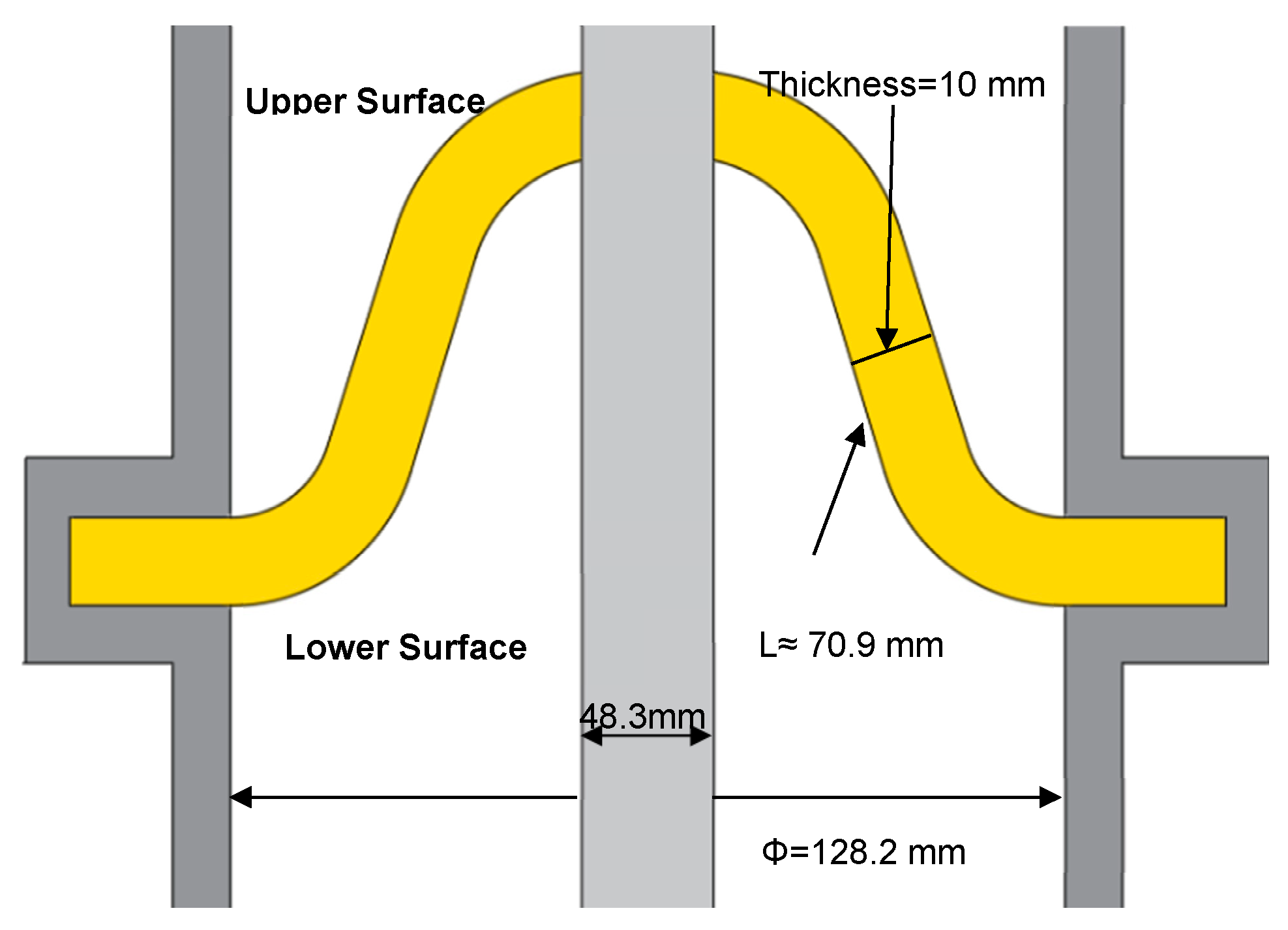
The initial shape of the spacer model to be optimized for DC use is shown in
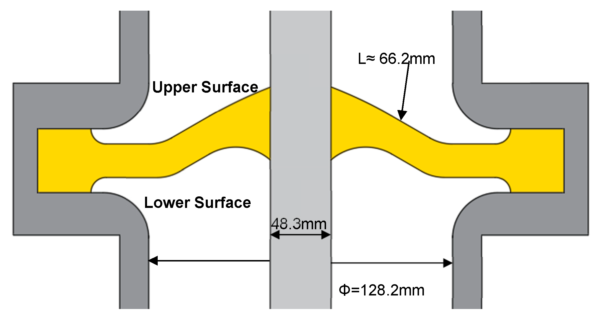
Figure 1. It is based on a commercial conventional full-size cone spacer used in HVAC 420 kV gas-insulated system reduced to ¼ scale. Namely the dimensions of the full-size gas-insulated system with respect to the central conductor outer diameter (D
c), the enclosure inner diameter (D
E), and the spacer shape (thickness and height) are all downsized by a factor of ¼ (0.25).
It should be noted that the ¼-size gas-insulated system has been chosen to reproduce the design of the commercial full-size HVAC 420 kV GIL/GIS in such a way to obtain approximately the same applied electric fields at the central HV conductor and at the grounded enclosure that are respectively given by EC = 2 V/[DC·Ln (DC/DE)] and EE = 2 V/[DE·Ln (DC/DE)]. Furthermore, since our goal is to develop spacers for 500 kV DC GIL/GIS use, to be able to verify by HV testing the spacer models subjected to the voltage of 131.3 kV that corresponds approximately to 500 kV using our DC power supply, rated to 150 kV.
3. Electric Field and Surface Charges Calculations
The electric field magnitude, E, distribution around the spacer under stationary DC voltage is obtained from the following equations:
where
is the current density (A/m
2),
is the conductivity (S/m), V is the electric potential (V).
The steady-state accumulated charges on the spacer surface can be calculated directly from the obtained electric fields by using Gauss’s law as follows:
where ε
G is the relative permittivity of the gas, ε
I the relative permittivity of the spacer material and ε
0 the permittivity of vacuum. E
GN and E
IN are the normal components of the electric field in the gas side and the spacer side, respectively.
The values of the electric potential, V, are fixed on the central conductor (applied voltage) and on the enclosure (ground voltage) according to Dirichlet boundary conditions. Von-Neumann boundary conditions are used to specify the continuity of the normal derivative of the electric potential at the interface gas-epoxy spacer.
Since the electric conductivity of the spacer’s material varies with the temperature, the profile of this latter inside the reduced scale gas-insulated system must be first determined to get the electric field distribution. To simplify the calculations, heat transfer by thermal conduction through both the gas and the spacer under thermal steady state condition is considered according to Equation (4):
where k is the thermal conductivity (W/m·K)
The temperatures at the central HV conductor Tc and at the grounded enclosure Te are given and lie within the permissible temperatures during HVDC GIS/GIL operation; namely, 105 °C at the HV conductor and 70 °C at the grounded enclosure.
4. Physical Properties of the HVDC GIS/GIL Insulation
4.1. Alternative Gas Mixture
Since we are intending to use CF
3I (30%)/CO
2 (70%) and C4-PFN (4%)/CO
2 (96%) gas mixtures, and so far there are no published information data available about the DC electrical conductivity, relative permittivity and thermal conductivity of these new gas mixtures, we have assumed in our calculations that their physical parameters are similar to those of SF
6, namely an electric conductivity of 10
−18 S/m [
6], a thermal conductivity of 0.0145 W/m·K and a relative permittivity of 1. It is noteworthy that in case the electric conductivity of the gas mixture might be higher, with a value up to 10
−15 S/m for example, the final results of the electric field distribution would not be affected as we found in our published work [
5].
4.2. Spacer’s Epoxy-Based Materials
Three types of epoxy-based materials were investigated: (i) conventional epoxy resin matrix filled with 60 to 66 wt.% of micro-sized alumina (Al
2O
3) commonly used in HVAC GIS/GIL systems, (ii) modified filled epoxy, and (iii) nonlinear resistive electric field grading material (FGM). Their thermal conductivity corresponds to 0.675 W/m·K [
7], and the relative permittivity is equal to 5 for (i) and (ii) and to 10 for (iii). The electric conductivity of the materials is electric field and temperature dependent whose models are described below.
This investigation will allow us to determine which material type yields a better electric field distribution. Using numerical simulations, the most appropriate approach for the fabrication of DC spacer models can be selected and allow their tests verification in the reduced scale GIL/GIS.
4.2.1. Conventional Alumina-Filled Epoxy
According to published literature [
8,
9,
10], the behavior of the DC electric conductivity with electric field and temperature, σ (E, T), of alumina-filled epoxy material has been found to be weakly dependent on the electric field up to 10 kV/mm and strongly dependent on temperature where the conductivity increases by 2 to 3 decades from 20 °C to the maximum operating temperature of 105 °C. In general, the conductivity is expressed by the following two empirical models:
where β is the field dependency coefficient (mm/kV), α is the temperature dependency coefficient (K
−1), σ
0 is a specific conductivity constant (S/m), k
B is Boltzmann constant (eV/K), and W
a is the thermal activation energy (eV).
In this paper, the conductivity formula of Equation (6) is used, where the characteristics of the alumina-filled epoxy as function of E and T are shown in
Figure 2 with σ
0 = 19.9 S/m, β = 0.08 mm/kV, W
a = 0.95 eV and K
B = 8.62 × 10
−5 eV/K.
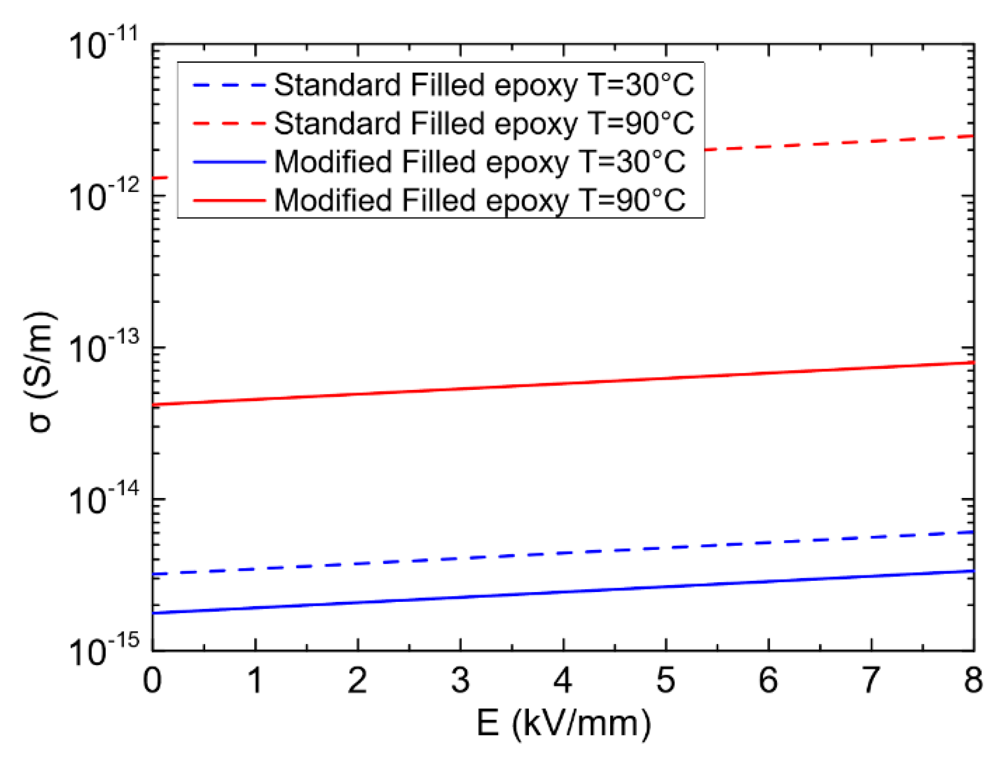
4.2.2. Modified Filled Epoxy
The modified filled epoxy material exhibits a lower increase of the electric conductivity with temperature compared to the conventional HVAC alumina-filled epoxy, which is represented by a decreased value of the thermal activation energy W
a. Indeed, for the development of HVDC cables, it has been found that improved cross-linked polyethylene (XLPE) based insulating materials with reduced temperature-dependent conductivity is one of the key solutions to obtain a desired electric field distribution compared to conventional HVAC XLPE materials [
11]. Therefore, this approach is considered to verify whether the reduced temperature dependence of the conductivity could be also beneficial for the improvement of the filled epoxy materials for HVDC GIL/GIS applications.
Practically, such modified filled epoxy material can be obtained by careful selection and tuning the constituents of the epoxy material formulation: nature of the epoxy base resin, hardener type, catalyst, other additives as well as the type of filler (alumina, silica (SiO2), etc.), its shape, size and concentration.
The behavior of the electric conductivity of the modified filled epoxy fits also the expression given in Equation (6) namely
, where β = 0.08 mm/kV, W
a = 0.5 eV and σ
0 = 3.64 × 10
−7 S/m. The latter was deduced from assuming that at 20 °C and under low applied electric field, its initial conductivity is equal to that of the conventional epoxy material.
Figure 3 plots the electric conductivity of the modified filled epoxy as function of the electric field at 30 °C and 90 °C together with the conventional alumina-filled epoxy with W
a = 0.95 eV to show the difference of the electric conductivity increase with temperature between the two materials.
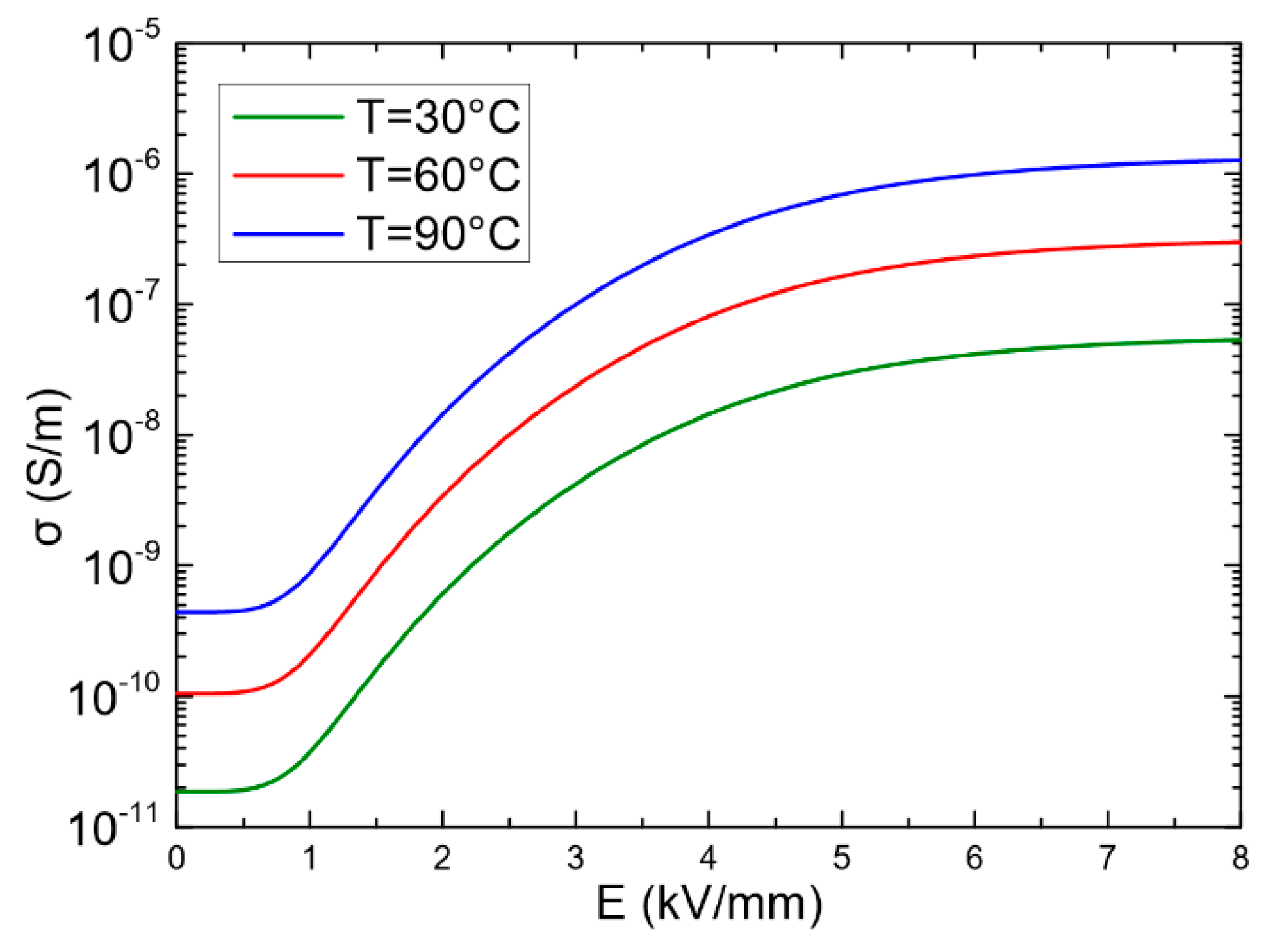
4.2.3. Nonlinear Resistive Field Grading Material (FGM)
Electric field grading materials are used to reduce the local enhancements of the electric field in high-voltage electrical apparatus. Nonlinear resistive electric field grading materials (FGM) are composite materials whose electric conductivity increases from a low value σ
0 at low electric fields to a high value at the switching field E
1 where the FGM becomes active. Among the mathematical models that describe such nonlinear behavior of σ
FGM (E), the following two expressions were reported [
12,
13]:
where σ
0 is the base conductivity (S/m), E
1 is the switching field strength (kV/mm), E
2 is the saturation field strength (kV/mm), γ and m are the slopes of nonlinearity, N
1 and N
2 are the smoothing parameters.
In this paper, the conductivity of Equation (7) is used. For the FGM to work, the base conductivity σ
0 should be higher than the conductivity of the adjacent gas insulation and its maximum value should not lead to excessive heat losses. The switching electric field strength, E
1, can be approximated to E = (applied voltage)/(spacer surface length). By considering the temperature effect, Equation (7) becomes:
where σ
0,T is the specific conductivity constant (S/m).
Among the different composite electric field grading materials that have been investigated for use in HVDC GIL/GIS applications, and which are still under development, there are: (i) zinc oxide (ZnO) microvaristor-filled epoxy material [
14], which has a strong field dependence, or high nonlinearity coefficient (γ > 20), of its conductivity. However, ZnO microvaristor filler is composed of other metal oxides (Bi
2O
3, Sb
2O
3, etc.), requires a well-controlled sintering process at temperatures above 900 °C, and its fabrication is mastered by only few ZnO varistors manufacturers. (ii) Epoxy filled with Iriotec 7000 particles (Merck Global) that consist of flake shaped mica particles covered with a nanoscale semiconducting antimony doped tin oxide (ATO) layer [
15]. This material shows a modest nonlinearity where the measured electric conductivity is in the range 10
−13–10
−11 S/m. (iii) silicon carbide (SiC)/Al
2O
3-filled epoxy [
16].
In this work, we are particularly interested in verifying the effectiveness of another novel FGM type with a moderate nonlinearity coefficient (γ < 8) that can be obtained by filling the epoxy resin matrix with two types of fillers (n/p doped semiconducting SiC with conducting/semiconducting bridging particles) namely doped SiC/CB (carbon black) or doped SiC/ATO. It should be noted that doped SiC/CB mixed with a rubber matrix was employed for electric field control in commercial HVDC cable accessories [
17,
18]. Such novel type of epoxy-based FGM has a nonlinear resistive conductivity σ
FGM (E, T) behavior that can match approximately the theoretical trend illustrated in
Figure 4 where σ
0,T = 3.83 × 10
−3 S/m, E
1 = 1 kV/mm, E
2 = 5 kV/mm, W
a = 0.5 eV, γ = 6.
5. Simulation Results
5.1. Optimization of DC Spacer Shape
In order to obtain the desirable shape of the spacer model minimizing local electric field enhancements at the critical regions under DC voltage, the following optimization criteria were considered when applying a direct voltage of 131.3 kV corresponding approximately, as mentioned previously, to the voltage 500 kV of the full-size GIL/GIS:
A minimum value of electric field magnitude at both the HV and the ground triple junctions (spacer–gas–HV conductor/grounded flange);
A small normal electric field on the spacer surface in order to minimize surface charge accumulation as recommended in [
19];
Sufficient creepage distance to prevent surface flashover caused by a high tangential electric field;
Minimized field enhancement along the spacer surface.
To fulfil these requirements, the geometrical modifications that have been carried out with respect to the initial shape and the flange (
Figure 1) are shown in
Figure 5, and they are as follow:
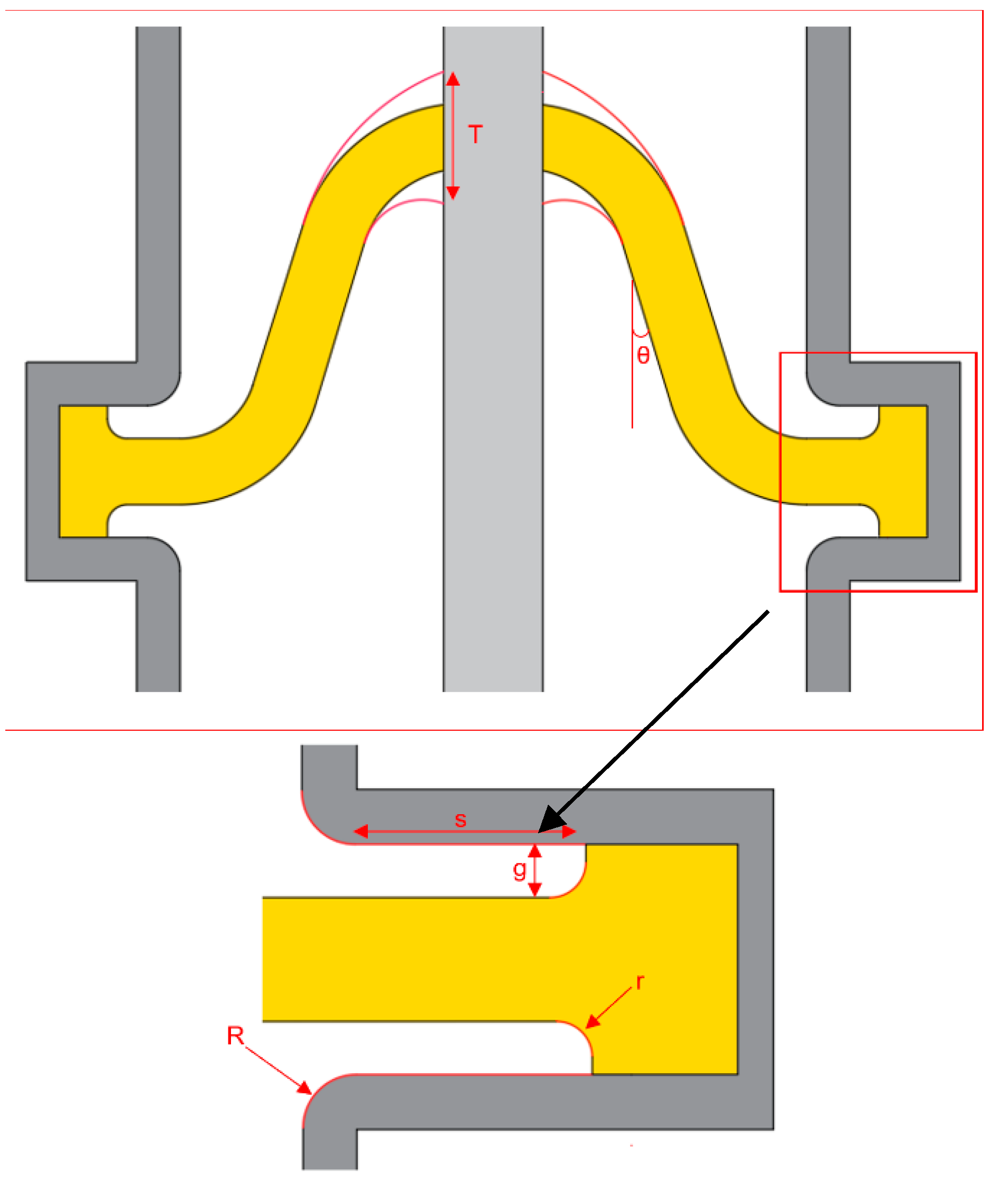
Increasing the radius (R) of the flange corner;
Introducing a small gas gap (g) at the spacer–flange interface to lower the electric field at the ground triple junction;
Increasing the spacer thickness (T) at the HV conductor contact to reduce the electric field at the HV triple junction;
Increasing the spacer inclination angle (θ) to lower the normal component of the electric field and, hence, minimize the surface charges accumulation;
Varying the distance (s) between the end of the flange radius and the spacer;
Varying the radius (r) of the spacer edge near the ground side.
It is important to recall that modifying the contact condition between the grounded flange and the epoxy spacer by the introduction of a gas gap (g) [
20] and increasing the spacer inclination angle (θ) [
21] has been found to be effective in avoiding local electric field intensification under DC voltage application.
COMSOL Multiphysics software was used to perform the numerical analysis of the electric field distribution and the geometrical optimization of the spacer model made of conventional HVAC alumina-filled epoxy with the electric conductivity behavior shown in
Figure 3, under a uniform temperature set to T
c = T
e = 30 °C.
The optimization procedure has been performed without the use of any mathematical optimization algorithm but by using the parametric sweep method according to the following steps: (i) the selected geometrical controllable parameters (R, g, s, T, r, θ) are given with the ranges of their variation indicated in
Table 1; (ii) the electric field distribution along the spacer is calculated under DC voltage energization over the variation ranges of the geometrical parameters; (iii) the stored electric field distribution results are displayed and analyzed to find the optimum values whose electric field distribution matches the targeted requirements of
Section 5. The obtained final optimized values are indicated in
Table 1.
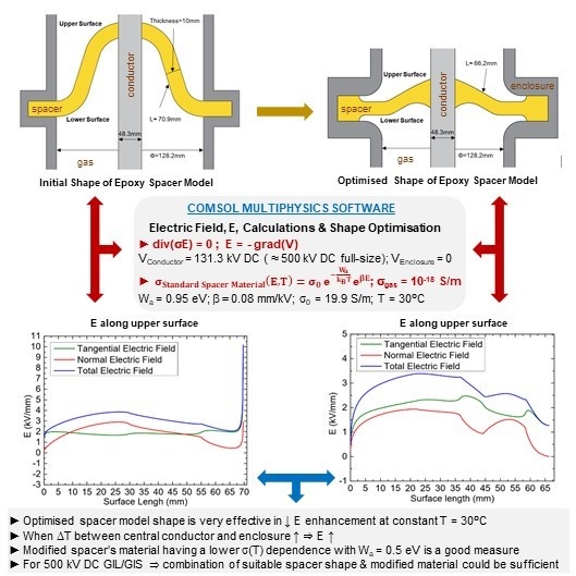
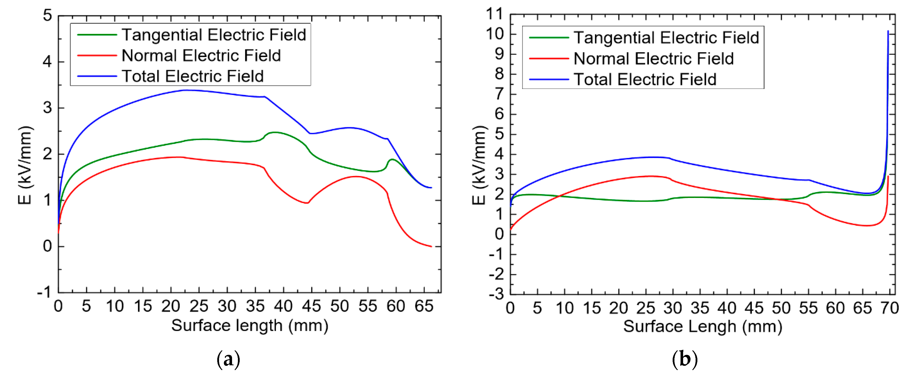
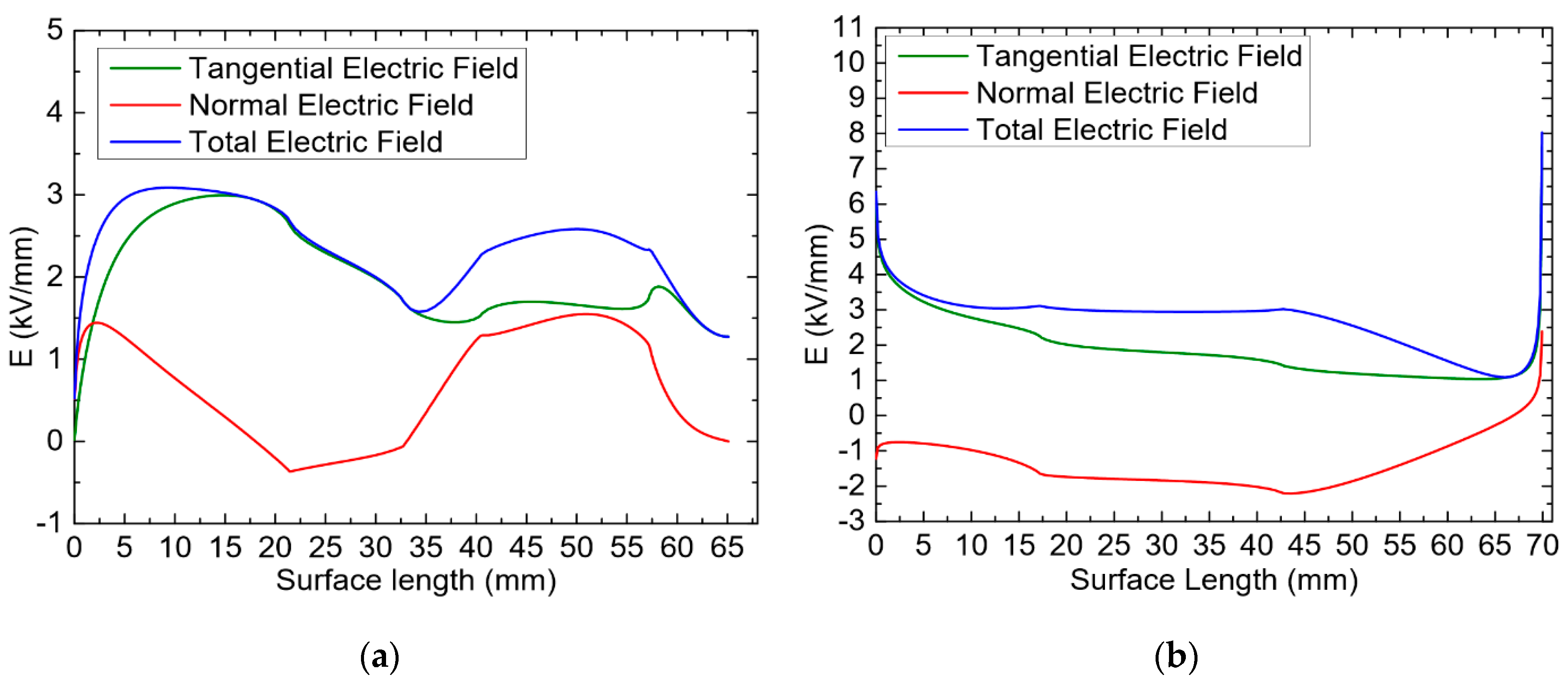
The resulting optimized configuration is illustrated in
Figure 6, and the obtained results of its electric field distributions (tangential, normal and total) are illustrated in
Figure 7a for the upper surface of the spacer and
Figure 8a for the lower surface of the spacer in comparison with those of the initial spacer profile presented in
Figure 7b and
Figure 8b.
As can be seen in
Figure 7b and
Figure 8b of the spacer’s initial profile, the maximum electric field values at both upper and lower surfaces occur at the critical ground triple junction (gas–spacer–grounded flange) and are 10 kV/mm at the upper side and 8 kV/mm at the lower side, thus exceeding the maximum applied electric value of 5.6 kV/mm at the inner conductor, whereas the maximum electric field of the improved optimized spacer is not located at the critical ground triple junction and is much lower, with 3.4 kV/mm at the upper surface side and 3.2 kV/mm at the lower one (
Figure 7a and
Figure 8a). At the ground triple junction, the maximum electric field is 1.2 kV/mm and is lower than the ground applied electric field of 2.1 kV/mm. Furthermore, the maximum value of the normal component of the electric field which is responsible for surface charges accumulation is about 3 kV/mm for the initial shape, whilst it is 2 kV/mm for the optimized one.
5.2. Effects of the Spacer’s Material and Temperature Gradient on the Electric Field Distribution
To account for the load conditions of the DC GIS/GIL, the temperatures of the HV conductor T
c and the grounded flange T
e were set to 90 °C and 50 °C, respectively, with a temperature gradient ΔT = 40 °C. The calculated temperature distribution around the optimized spacer model is shown in
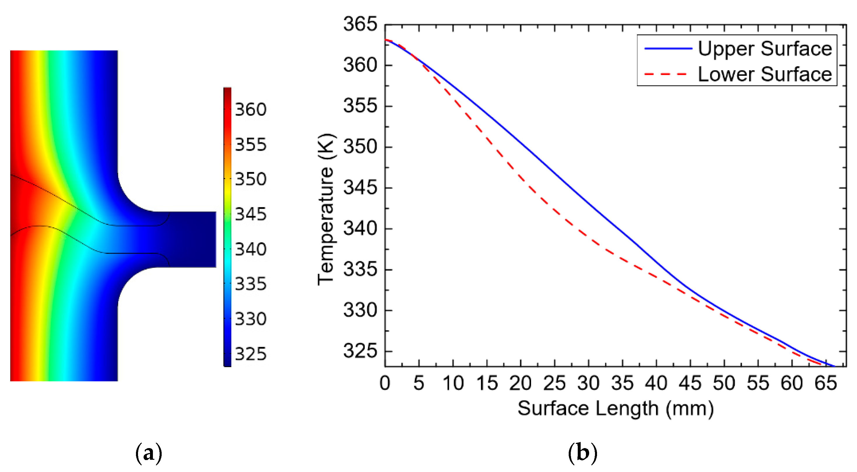
Figure 9.
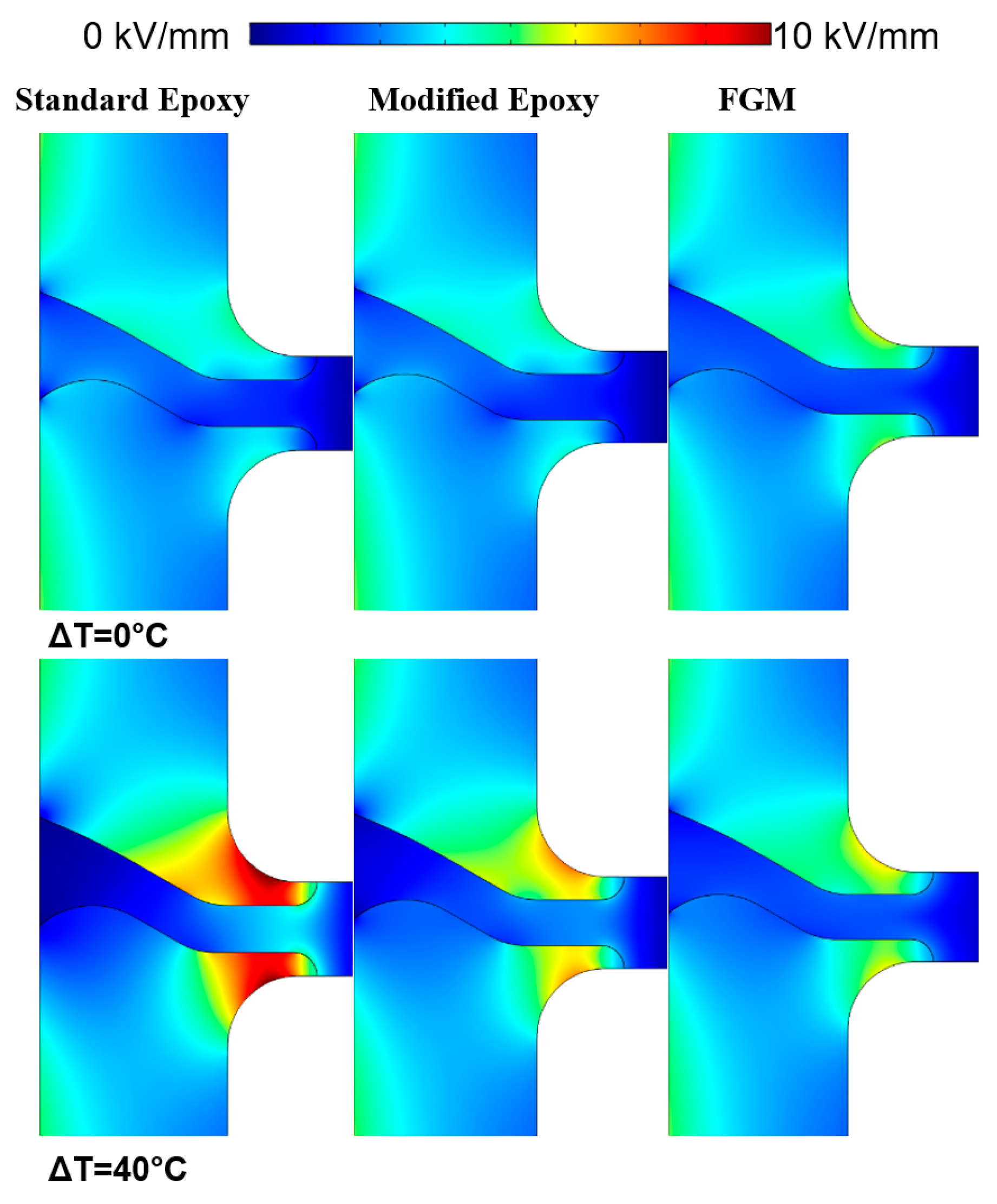
The results of the electric field distributions around the optimized spacer made of different types of epoxy-based materials at uniform temperature (30 °C) and in the presence of a temperature gradient of 40 °C are given in
Figure 10.
As can be seen in
Figure 10, the presence of a temperature gradient influences the electric field distribution around the spacer for all types of materials where the maximum electric field strength is shifted towards the grounded flange compared to the uniform temperature case ΔT = 0 °C. It is important to note that such a phenomenon of electric field displacement towards cooler regions where the electric conductivity is lower than the one of the warmer regions near the HV conductor is well known when HVDC GIL/GIS are under load operation, and this was reported in many works, such as [
22].
However, a significant increase in the electric field is observed for the conventional HVAC alumina-filled epoxy. Furthermore, it is worth emphasizing that the electric field is also intensified at the flange’s rounded edges where it reaches 11.5 kV/mm instead of 3.5 kV/mm at the upper side and 10 kV/mm instead of 2.2 kV/mm at the lower side.
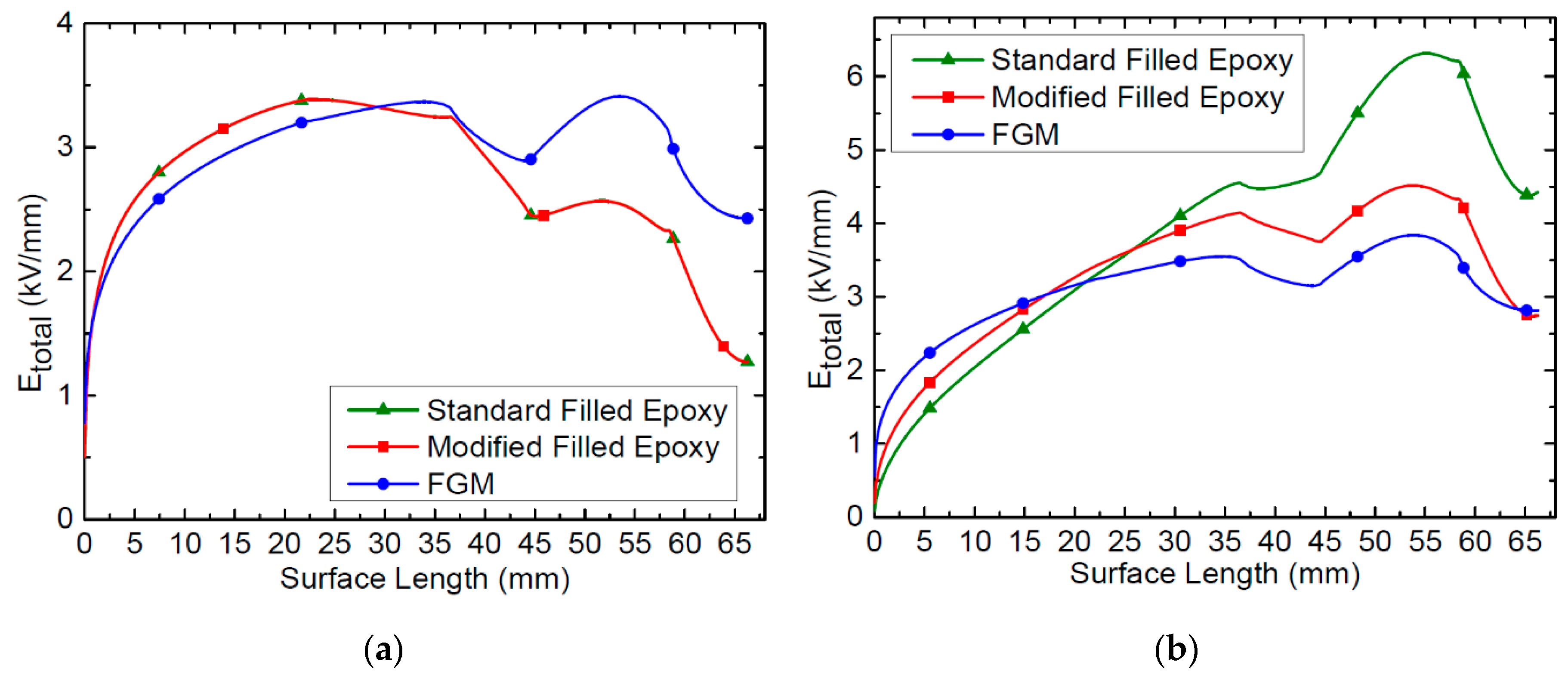
The total electric field E
total distributions along the upper surface of the optimized spacer model made of the AC standard alumina-filled epoxy material, the modified filled epoxy material and the FGM, are presented in
Figure 11a,b for uniform temperature (ΔT = 0 °C) and temperature gradient (ΔT = 40 °C), respectively, under a DC voltage of 131.3 kV.
With a uniform temperature of 30 °C (
Figure 11a), the obtained electric field distributions for the standard alumina-filled epoxy and the modified filled epoxy material are the same, since, as shown in
Figure 3, both materials have the same weakly electric field-dependent conductivity (β = 0.08 mm/kV) and the conductivity difference at 30 °C for both materials is low. However, for the FGM, although the maximum value of the total electric field remained unchanged, the electric field at the ground triple junction is increased to 2.4 kV/mm compared to the other two materials, where it is 1.2 kV/mm.
In the presence of a high temperature gradient (ΔT = 40 °C), as can be seen in
Figure 11b, the most relevant finding is that the use of modified filled epoxy material with the reduced temperature dependence of the conductivity represented by a lower thermal activation energy (W
a = 0.5 eV) compared with the conventional alumina-filled epoxy with W
a = 0.95 eV results in a significant reduction of the electric field enhancement. Compared with the standard alumina-filled epoxy, the maximum value of the total electric field is decreased from 6.5 kV/mm to 4.5 kV/mm without exceeding the maximum applied conductor electric field of 5.57 kV/mm. Furthermore, the electric field at the critical ground triple junction is lowered from 4.5 kV/mm to 2.8 kV/mm. The electrical field enhancement at the rounded edges of the flange is much improved, too (
Figure 10). The FGM with a low nonlinearity coefficient does not add any further minimization of the electric field at the critical ground triple junction.
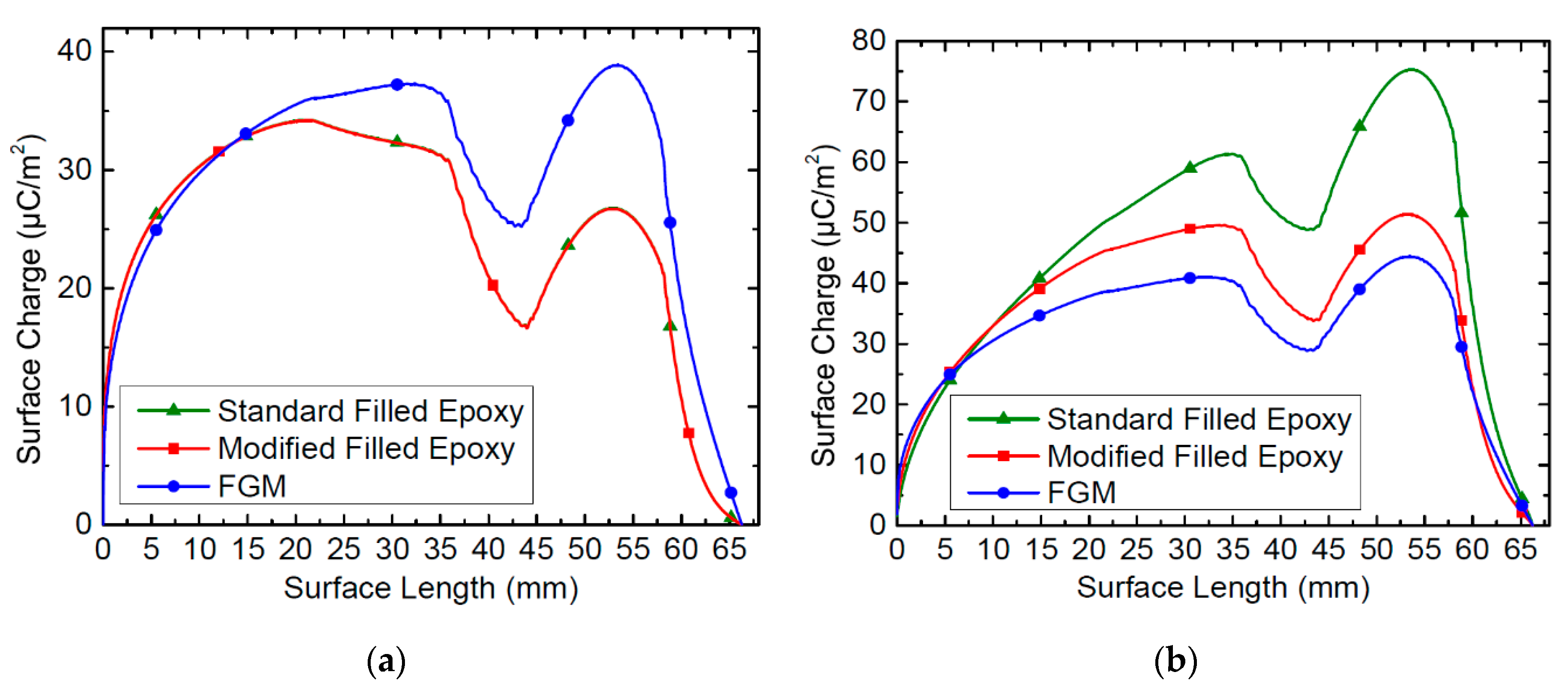
5.3. Surface Charges Accumulation
Figure 12a,b present the accumulated charges along the spacer’s upper surface under stationary DC applied voltage of 131.3 kV at a uniform temperature of 30 °C (ΔT = 0 °C) and a thermal gradient of ΔT = 40 °C between the central HV conductor (90 °C) and the earthed flange (50 °C), respectively, for the standard AC alumina-filled epoxy, modified filled epoxy and FGM. As can be seen, positive charges accumulate on the whole surface of the spacer. Numerical electric field computations and the use of Equation (3) to obtain the normal component of electric field at the gas side, E
GN, revealed that the highest values in regions where the electric conductivity is very low (10
−18 S/m) and that, at the spacer side, E
IN is negligible. Furthermore, the direction of the normal electric field lines is outward, from the surface from the spacer towards the gas.
At uniform temperature, the maximum surface charge density is 34.2 µC/m2 for both the standard AC alumina-filled epoxy and modified filled epoxy, since they have the same weak electric field-dependent conductivity, and 38.9 µC/m2 for the FGM.
However, for ΔT = 40 °C, the surface charge density increases for the three materials (
Figure 12b). Such impact of temperature gradient on surface charges accumulation on spacers has been also obtained in the thermo-electrical simulation investigation of the work on insulators in 500 kV DC-GIL [
23].
The most significant increase concerns the standard AC alumina-filled epoxy material exhibiting a higher temperature-dependent electric conductivity (Wa = 0.95 eV) where the maximum surface charge density is more than two times larger (75.3 µC/m2) than without a thermal gradient (34.2 µC/m2). The surface charge density of modified filled epoxy with a weaker temperature-dependent electric conductivity (Wa = 0.5 eV) is reduced with a value of 51.4 µC/m2 and of the FGM is 44.4 µC/m2. This indicates that a weak dependence of the electric conductivity with temperature may be very effective in reducing surface charge formation under DC energization, and thus modified filled epoxy should be used in HVDC GIL/GIS spacers.
6. Conclusions
The relevant findings of this work can be summarized as follows:
The geometrically optimized spacer model profile for DC operation is very effective in reducing the enhancement of the electric field at the critical locations where the resulting maximum electric field along the spacer is within the acceptable range.
The presence of a high temperature gradient has a significant influence on the electric field distribution along the spacer and shifts the maximum electric field from the central HV conductor towards the grounded flange side. One of the key mitigations to reduce this electric field enhancement is by using new modified filled epoxy material with a weakly temperature-dependent conductivity, namely a lower thermal activation energy than that of the conventional AC alumina-filled epoxy.
The increase in temperature gradient leads also to charge accumulation increase on the spacer surface with the highest surface charge density when using the AC standard material.
A novel nonlinear resistive field grading material (FGM) with a moderate nonlinearity coefficient (γ < 8) is also effective but does not add further improvement.
The most relevant finding is that once the spacer profile had been initially well optimized for DC energization the use of modified filled epoxy may be sufficient for 500 kV DC GIL/GIS applications, provided that the maximum temperature gradient (ΔT) during load operation is not very high.
Current and future work involves the fabrication and testing of the optimized scaled DC spacer. The scaled GIL/spacer will be experimentally characterized with alternative gases mixtures using CF3I/CO2 and C4-PFN/CO2.
Author Contributions
Conceptualization, N.Z.; validation, N.Z. and M.A.H.; formal analysis, H.L. and N.Z.; investigation, N.Z. and H.L.; writing—original draft preparation, N.Z.; writing—review and editing, N.Z., H.L. and M.A.H.; visualization, N.Z. All authors have read and agreed to the published version of the manuscript.
Funding
This research received no external funding.
Acknowledgments
This work is supported by the EU/Welsh Government funded project FLEXIS.
Conflicts of Interest
The authors declare no conflict of interest.
References
- Hasegawa, T.; Yamaji, K.; Hatano, M.; Endo, F.; Rokunohe, T.; Yamagiwa, T. Development of insulation structure and enhancement of insulation reliability of 500 kV dc GIS. IEEE Transact. Power Deliv. 1997, 12, 194–202. [Google Scholar] [CrossRef]
- Sakai, T.; Furuyashiki, T.; Kato, K.; Okubo, H. Electric field analysis and Electrical insulation performance for Solid insulator in HVDC gas insulated switchgear. In Proceedings of the International Symposium on High Voltage Engineering (ISH), Pilsen, Czech Republic, 23–28 August 2015. [Google Scholar]
- Chen, L.; Widger, P.; Elnaddab, K.; Albano, M.; Griffiths, H.; Haddad, A. CF3I gas and its mixtures: Potential for electrical insulation. In Proceedings of the CIGRE Conference, Paris, France, 24–29 August 2014. [Google Scholar] [CrossRef]
- Seeger, M.; Smeets, R.; Ito, H.; Claessens, M.; Dullni, E.; Falkingham, L.; Franck, C.; Gentils, F.; Hartmann, W.; Kieffel, Y.J.E. Recent development and interrupting performance with SF6 alternative gases. In Proceedings of the Electra Mining Botswana 2017, Gaborone, Botswana, 12–14 September 2017. [Google Scholar]
- Li, H.; Zebouchi, N.; Haddad, A. Theoretical and practical investigations of spacer models for future HVDC GIL/GIS applications. In Proceedings of the International Symposium on High Voltage Engineering (ISH), Budapest, Hungary, 26–30 August 2019. [Google Scholar] [CrossRef]
- Zavattoni, L.; Vu, C.T.; Vinson, P.; Girodet, A. Leakage current measurements in direct current gas insulated substations equipment. In Proceedings of the IEEE International Conference on Dielectrics, Montpellier, France, 3–7 July 2016. [Google Scholar]
- Kochetov, R.; Andritsch, T.; Morshuis, P.H.F.; Smit, J.J. Thermal and electrical behaviour of epoxy-based microcomposites filled with Al2O3 and SiO2 particles. In Proceedings of the Conference Record of the 2010 IEEE International Symposium on Electrical Insulation, San Diego, CA, USA, 6–9 June 2010. [Google Scholar] [CrossRef]
- Volpov, E. Electric field modeling and field formation mechanism in HVDC SF6 gas insulated systems. IEEE Transact. Dielectr. Electr. Insulat. 2003, 10, 204–215. [Google Scholar] [CrossRef]
- Yahyaoui, H.; Notingher, P.; Agnel, S.; Kieffel, Y.; Girodet, A. Analysis of conduction mechanisms in alumina-filled epoxy resin under dc field and temperature. In Proceedings of the Annual Report Conference on Electrical Insulation and Dielectric Phenomena, Shenzhen, China, 20–23 October 2013. [Google Scholar] [CrossRef]
- Gremaud, R.; Zhao, Z.; Baur, M. Measurement of DC conduction in alumina-filled epoxy. In Proceedings of the IEEE International Conference on Dielectrics (ICD), Montpellier, France, 3–7 July 2016. [Google Scholar] [CrossRef]
- Qin, S.; Boggs, S. Design considerations for high voltage DC components. IEEE Electr. Insulat. Mag. 2012, 28, 36–44. [Google Scholar] [CrossRef]
- Kwon, I.; Koo, J.; Lee, H.; Koo, J.; Lee, B. DC electric field control of ending box-air (EB-A) type outdoor termination under DC voltage stress. In Proceedings of the 20th International Symposium on High Voltage Engineering, Buenos Aires, Argentina, 28 August–1 September 2017. [Google Scholar]
- Blatt, S.; Hinrichsen, V. Mathematical Model for Numerical Simulation of Current Density in Microvaristor Filled Insulation Materials. IEEE Transact. Dielectr. Electr. Insulat. 2015, 22, 1161–1170. [Google Scholar] [CrossRef]
- Tenzer, M.; Secklehner, M.; Hinrichsen, V. Short and long term behavior of functionally filled polymeric insulating materials for HVDC insulators in compact gas-insulated systems. In Proceedings of the Nordic Insulation Symposium, Trondheim, Norway, 9–12 June 2013. [Google Scholar] [CrossRef] [Green Version]
- Winter, A.; Kindersberger, J.; Tenzer, M.; Hinrichsen, V.; Zavanttoni, O.L.; Muhr, M.; Imamovic, D. Solid/gaseous insulation systems for compact HVDC solutions. In Proceedings of the CIGRE Conference, Paris, France, 25–29 August 2014. [Google Scholar]
- Li, C.; Lin, C.; Hu, J.; Liu, W.; Li, Q.; Zhang, B.; He, S.; Yang, Y.; Liu, F.; He, J. Novel HVDC spacers by adaptively controlling surface charges—Part I: Charge transport and control strategy. IEEE Transact. Dielectr. Electr. Insulat. 2018, 25, 1238–1247. [Google Scholar] [CrossRef]
- Martensson, E.; Nettelbled, B.; Gafvert, U.; Palmqvist, L. Electricl properties of field grading materials with silicon carbide and carbon black. In Proceedings of the IEEE International Conference on Conduction and Breakdown in Solid Dielectrics, Vasteras, Sweden, 22–25 June 1998. [Google Scholar] [CrossRef]
- Sörqvist, T.; Christen, T.; Jeroense, M.; Mondiet, V.; Papazyan, R. HVDC light cable systems-highlighting the accessories. In Proceedings of the 21st Nordic Insulation Symposium (Nordis 2009), Gothenburg, Sweden, 15–17 June 2009. [Google Scholar]
- Volpov, E.; Insulation, E. Dielectric strength coordination and generalized spacer design rules for HVAC/DC SF6 gas insulated systems. IEEE Transact. Dielectr. Electr. Insulat. 2004, 11, 949–962. [Google Scholar] [CrossRef]
- Koo, J.; Hwang, J.; Kwon, I.; Lee, H.; Shin, W.; Lee, B. Modeling and simulation of HVDC epoxy spacer for SF6 gas insulated system. In Proceedings of the International Symposium on High Voltage Engineering (ISH), Pilsen, Czech Republic, 23–28 August 2015. [Google Scholar]
- Nakane, R.; Takabayashi, K.; Kato, K.; Okubo, H. Electric field analysis and electrical insulation performance for gas-solid composite insulation in HVDC GIS. In Proceedings of the International Symposium on High Voltage Engineering (ISH), Buenos Aires, Argentina, 28 August–1 September 2017. [Google Scholar]
- Koch, H.; Imamovic, D.; Lutz, B.; Juhre, K.; Neidhart, T.; Rogler, R. High power underground transmission for HVDC. In Proceedings of the CIGRE Conference, Paris, France, 22–26 August 2016. [Google Scholar]
- Zhou, H.; Ma, G.; Li, C.; Shi, C.; Qin, S. Impact of temperature on surface charges accumulation on insulators in SF6-filled DC-GIL. IEEE Transact. Dielectr. Electr. Insulat. 2017, 24, 601–610. [Google Scholar] [CrossRef]
Figure 1.
Initial profile of the reduced-scale spacer model.
Figure 1.
Initial profile of the reduced-scale spacer model.
Figure 2.
Electric field and temperature dependent conductivity of the standard high-voltage alternating current (HVAC) alumina-filled epoxy.
Figure 2.
Electric field and temperature dependent conductivity of the standard high-voltage alternating current (HVAC) alumina-filled epoxy.
Figure 3.
Plot of the conductivity of the modified filled epoxy material (Wa = 0.5 eV) and conventional alumina-filled epoxy (Wa = 0.95 eV).
Figure 3.
Plot of the conductivity of the modified filled epoxy material (Wa = 0.5 eV) and conventional alumina-filled epoxy (Wa = 0.95 eV).
Figure 4.
Conductivity of novel nonlinear resistive field grading material (FGM) with temperature and electric field with a moderate nonlinear coefficient γ = 6.
Figure 4.
Conductivity of novel nonlinear resistive field grading material (FGM) with temperature and electric field with a moderate nonlinear coefficient γ = 6.
Figure 5.
An illustration of the geometrical parameter variables (T, θ, g, s, r, R) for the spacer model optimization.
Figure 5.
An illustration of the geometrical parameter variables (T, θ, g, s, r, R) for the spacer model optimization.
Figure 6.
Optimized shape of the spacer model for DC energization.
Figure 6.
Optimized shape of the spacer model for DC energization.
Figure 7.
Computed tangential, normal, and total electric field distributions on the upper surface of the optimized spacer (a) in comparison with that of the initial configuration (b).
Figure 7.
Computed tangential, normal, and total electric field distributions on the upper surface of the optimized spacer (a) in comparison with that of the initial configuration (b).
Figure 8.
Computed tangential, normal, and total electric field distributions on the lower surface of the optimized spacer (a) in comparison with that of the initial configuration (b).
Figure 8.
Computed tangential, normal, and total electric field distributions on the lower surface of the optimized spacer (a) in comparison with that of the initial configuration (b).
Figure 9.
(a) Temperature distribution around the optimized spacer model with Tc = 90 °C and Te = 50 °C. (b) Temperature distribution along the upper and lower surfaces.
Figure 9.
(a) Temperature distribution around the optimized spacer model with Tc = 90 °C and Te = 50 °C. (b) Temperature distribution along the upper and lower surfaces.
Figure 10.
Electric field distributions around the spacer model made of different materials at uniform temperature (T = 30 °C) and ΔT = 40 °C under DC voltage of 131.3 kV.
Figure 10.
Electric field distributions around the spacer model made of different materials at uniform temperature (T = 30 °C) and ΔT = 40 °C under DC voltage of 131.3 kV.
Figure 11.
Electric field magnitude distribution at the spacer’s upper surface under 131.3 kV DC for ΔT = 0 °C (a) and ΔT = 40 °C (b) of the standard HVAC alumina-filled epoxy, modified filled epoxy and field grading material (FGM).
Figure 11.
Electric field magnitude distribution at the spacer’s upper surface under 131.3 kV DC for ΔT = 0 °C (a) and ΔT = 40 °C (b) of the standard HVAC alumina-filled epoxy, modified filled epoxy and field grading material (FGM).
Figure 12.
Accumulated charges at the spacer’s upper surface under 131.3 kV DC for ΔT = 0 °C (a) and ΔT = 40 °C (b) of the standard filled epoxy, modified filled epoxy and FGM.
Figure 12.
Accumulated charges at the spacer’s upper surface under 131.3 kV DC for ΔT = 0 °C (a) and ΔT = 40 °C (b) of the standard filled epoxy, modified filled epoxy and FGM.
Table 1.
Controlled geometrical parameters and final optimized values.
Table 1.
Controlled geometrical parameters and final optimized values.
| Geometrical Parameter | Initial Value | Variation Range | Optimized Value |
|---|
| Flange radius (R) | 0 mm | 0–15 mm | 15 mm |
| Gas gap (g) | 0 mm | 0–5 mm | 5 mm |
| Distance (s) | 0 mm | 0–8 mm | 4 mm |
| Thickness (T) | 10 mm | 10–25 mm | 23 mm |
| Radius (r) | 0 mm | 0–5 mm | 5 mm |
| Inclination angle (θ) | 17° | 17°, 45°, 60° | 60° |
© 2020 by the authors. Licensee MDPI, Basel, Switzerland. This article is an open access article distributed under the terms and conditions of the Creative Commons Attribution (CC BY) license (http://creativecommons.org/licenses/by/4.0/).


