Article

Improved Predictive Control in Multi-Modular Matrix Converter for Six-Phase Generation Systems

1
Facultad de Ingeniería, Universidad de Talca, Curicó 3341717, Chile
2
Facultad de Ingeniería, Universidad Nacional de Asunción, Luque 2060, Paraguay
3
Faculty of Engineering, University of Nottigham, Nottingham NG7 2RD, UK
*
Author to whom correspondence should be addressed.
Current address: Merced 437, Universidad de Talca, Curicó 3341717, Chile.
Energies 2020, 13(10), 2660; https://doi.org/10.3390/en13102660
Submission received: 14 April 2020 / Revised: 11 May 2020 / Accepted: 18 May 2020 / Published: 25 May 2020
(This article belongs to the Special Issue Control Strategies for Power Conversion Systems)

Abstract

:
Distributed generation systems are emerging as a good solution as part of the response to the world’s growing energy demand. In this context multi-phase wind generation systems are a feasible option. These systems consist of renewable AC sources which requires efficient and controlled power conversion stages. This work proposes a novel predictive current control strategy that takes advantage of a multi-modular matrix converter topology in the power stage of a six-phase generation system. The proposed method uses a coupling signal between the modules to decrease the error and the total harmonic distortion compared to independent control of each module. Experimental results validate the new control strategy showing the improvement regarding the target parameters.

1. Introduction

Distributed generation is emerging as a new energy paradigm mainly based on the interaction between several renewable energy sources often merging in a synergistic manner using small-scale, decentralized, local on-side generation [1]. Among all the different generation sources, one of the most promising is wind energy harvesting [2,3] and very active research is focused on multi-phase wind energy generator (MWEG) systems [4]. Multiple three-phase windings in MWEG systems are very convenient for wind turbines (WT) and several studies employing these topologies have been conducted [5]. Some of the main features of MWEG systems consist of: (i) the possibility to split the power and the current between a higher number of phases allowing per-phase inverter power rating reduction; (ii) capability to work continuously even in presence of phase and/or inverter faults; (iii) increasing availability, working time, and consequently, the annual energy yield [6,7]. Regarding MWEG, the six-phase wind energy generator (SpWEG) with two sets of three-phase stator windings spatially shifted by 30 or 60 electrical degrees and isolated neutral points are probably the most widely discussed topologies with fully rated back-to-back converter system focused on distributed generation (DG) [8]. Several power electronic grid-connected converters (GCC) have been used for DG systems, for example the active front-end (AFE), cascaded multilevel converters, neutral-point-clamped (NPC) topologies and modular multilevel converters [9,10,11,12,13]. These topologies must ensure an efficient current control to achieve aims of desired active and reactive flux control, with minimum current and voltage harmonic distortions fulfilling defined quality standards. However, most of the topologies are AC-DC-AC, requiring energy storage elements (i.e., capacitor banks) which add weight, volume and failure modes to the GCC topologies. Research has focused on the development of a flexible direct AC-AC power interface based on a modular architecture capable of interconnecting AC sources with the grid under the DG frame without the use of storage elements. In this context, the matrix converter (MC) emerges as a plausible solution, providing a three-phase sinusoidal voltage with variable amplitude and frequency using fully controlled bi-directional switches without the use of storage energy elements [14]. Regarding the control of conversion stages, several methods have been addressed such as: pulse width modulation (PWM), space vector modulation (SVM), fuzzy control and model predictive control (MPC). [15,16,17,18]. MPC has been implemented successfully for a number of applications as: current control [19,20], voltage control [21], speed control [22], torque control [23], steady-state error suppression [24] and current control combining multi-phase machines and multi-modular direct matrix converters (MMC) [25,26], among others.
Some advantages of MPC are: (i) it is a more direct control strategy which can reduce the complexity of other methods for MC control; (ii) several control objectives (such as output current, input reactive power minimisation, source current control, etc.) and constraints can be considered using different cost functions; (iii) fast and accurate performances in the transient and steady states; and (iv) high controller bandwidth [27]. Among the advantages, the capability of including several new control objectives through variations in the cost function is one of the most interesting and is exploited in this work. Even when past proposals have met relevant international standards injecting half of the desired current per module to achieve the desired injected current, it can be noted that when multi-modular topologies are used, a coupling signal between the parallel three-phase MC modules can be used to improve the performance taking an advantage of the predicted error for one module including this error in the reference of the second to reduce the total error and the total harmonic distortion (THD). The main contribution of this research is the proposal of a novel cost function in the MPC that includes a coupling signal between the modules of a MMC topology for SpWEG systems improving the response in terms of mean square error (MSE) and THD compared with the typical MPC. In the following section the model of the conversion stage is presented.

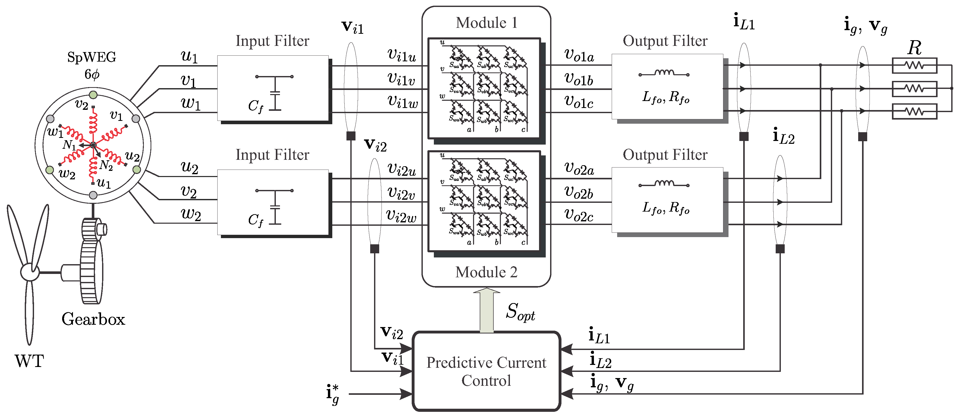
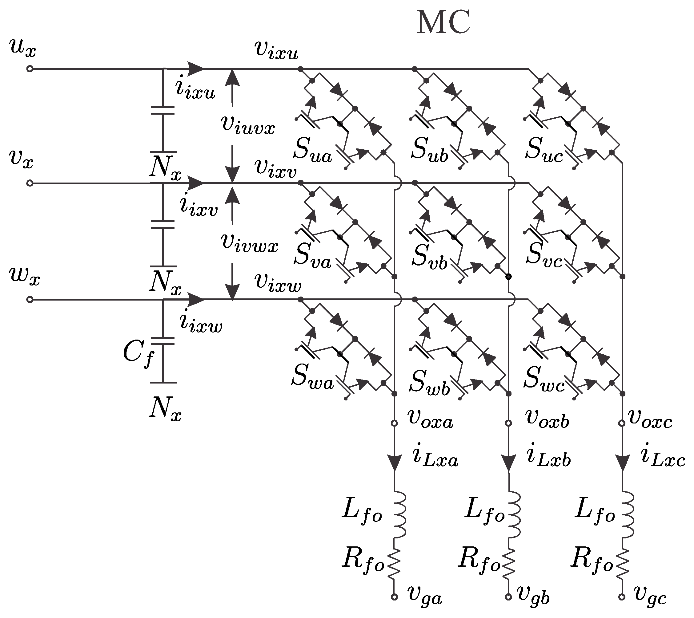
2. Model of the Power Conversion System

As shown in Figure 1, the proposed topology consists of two three-phase MC modules connected to the SpWEG by using a passive (C) input filter and then connected to the grid by an output (L) filter. Each one of these modules is represented by the power electronic module shown in Figure 2.
In this case, generated voltages by the SpWEG are indicated as u x , v x and w x where x { 1 , 2 } denotes the corresponding module. Input voltages of the MC are v i x u , v i x v and v i x w and input currents are i i x u , i i x v and i i x w , respectively. The output voltages of the MC with respect to the corresponding SpWEG neutral point ( N 1 or N 2 ) are v o x a , v o x b and v o x c . Moreover, output currents are i L x a , i L x b and i L x c , respectively. Finally, the output filter voltages (i.e., the connected to the grid or load side) are v g a , v g b and v g c .
Each MC is composed of nine bidirectional power switches, which can generate 27 feasible switching states [28]. If the three-phase vectors of voltages and currents are defined as:
v i x = v i x u v i x v v i x w , v o x = v o x a v o x b v o x c , v g = v g a v g b v g c , i i x = i i x u i i x v i i x w , i L x = i L x a i L x b i L x c ,
then the following vectorial equations relate the input and output voltages and currents through the switching states of the MC:
v o x = S · v i x , i i x = S T · i L x ,
where S is the instantaneous transfer matrix, defined as:
S = S u a S u b S u c S v a S v b S v c S w a S w b S w c ,
and S x y { 0 , 1 } represents the state of the corresponding switch.
In order to avoid short circuits on the input side and ensure an uninterrupted current flow on the load side, the switching signals S x y must satisfy the following condition:
S u y + S v y + S w y = 1 . y { a , b , c } .
The dynamic model of the passive output filter is defined as:
v o x v g = L f o d i L x d t + R f o i L x ,
where R f o and L f o are the output filter leakage resistance and inductance, respectively.

3. Control Strategy

As mentioned on the first section, this paper proposes an improvement of a classical MPC for a MMC topology in a SpWEG system. Model predictive control is one of the most promising high performance control strategies due to its excellent dynamic behavior and flexibility in the definition of control objectives and have been widely used on SpWEG systems control [29]. The MPC technique uses a mathematical model of the system to predict the future behavior of the variables to be controlled. The inherent discrete nature of power converters simplifies the MPC optimization algorithm in to the prediction of the system behavior only for the set of feasible switching states. This approach is called finite control set MPC (FCS-MPC). In a simplified manner, the FCS-MPC applied works as follows: (i) the converter is modeled as a finite state system, (ii) the model of the output filter is used to predict the current for every feasible switching state, (iii) a cost function is defined which represents the desired system response and, finally, (iv) the switching state that minimize the cost function is selected to be applied in the next sampling time. Based on this four steps, a technique using an independent MPC for each module will be compared again a coupled MPC proposal in order to control the current provided by a six-phase generator. Then, the first step in the implementation implies to obtain a precise model. In this case, the discrete model of the system is derived from the continuous time linear system for the input filter, the output filter, and the ( α β ) transform defined in [30] as:
y α = 2 3 y a 0.5 y b 0.5 y c , y β = 2 3 3 2 y b 3 2 y c .
The output filter current prediction, using the forward Euler discretization of (5), is:
i L x ( k + 1 ) = 1 R f o T s L f o i L x ( k ) + T s L f o v x ( k ) v o x ( k ) ,
where T s is the sampling time, i L x ( k ) and v o x ( k ) are measured, and  v x ( k ) is calculated for all switching combinations to predict the next value of the output currents and evaluate the cost function in order to select the optimum solution.
In the considered case, the main target consists in control every output current ( i L x ) and given that the desired current is the sum of all module currents, the reference currents for each module are defined as half of the desired total currents as:
i L x * = i g * 2 ,
where i L x represent the current supplied by the x module and i g * the reference current that is required to be supplied to the load or grid side.
Using (6), it is possible to calculate all the currents in ( α β ) sub-space that reduces the computations solving only two equations (i.e.,  α β components) instead of three (i.e., every phase of a three-phase system). Thereafter, for each feasible switching vectors the corresponding cost function is evaluated.
In the first case, every module is considered as an independent source injecting half of the desired total current, that is carried out using the typical predictive current control cost function:
g 1 = i L 1 α * i L 1 α 2 + i L 1 β * i L 1 β 2 , g 2 = i L 2 α * i L 2 α 2 + i L 2 β * i L 2 β 2 .
where i L 1 α * , i L 2 α * , i L 1 β * and i L 2 β * denote the reference currents in α β and i L 1 α , i L 2 α , i L 1 β and i L 2 β correspond to the predicted currents in α β , respectively. From the evaluation of all the possible vectors, the algorithm selects the optimal switching combination to be applied at the next sampling period.
In the second case, the proposal consist of take advantage of the fact that the predicted error in module 1 can be known given that the optimal switching vector for the first module can be determined before the calculation of the corresponding for module 2. Then the predicted error could be introduced in the cost function of the second module as a coupling signal, achieving an error reduction in the total current that is the sum of both. Thereby, the first part of Equation (9) is the same to determine the optimal vector for module 1. Once the vector to be applied in module 1 is determined, it is possible to predict the future error as:
e p α = i L 1 α * i L 1 α o p t , e p β = i L 1 β * i L 1 β o p t ,
been i L 1 α o p t and i L 1 β o p t the predicted output currents in α β frame applying the optimal chosen vector for module 1. In this way, the cost functions are defined as follows:
g 1 = i L 1 α * i L 1 α 2 + i L 1 β * i L 1 β 2 , g 2 = i L 2 α * i L 2 α + e p α 2 + i L 2 β * i L 2 β + e p β 2 ,
Using these cost functions inside the predictive control frame, in the next section a comparison among the independent control and the coupled control are presented in simulation environment.

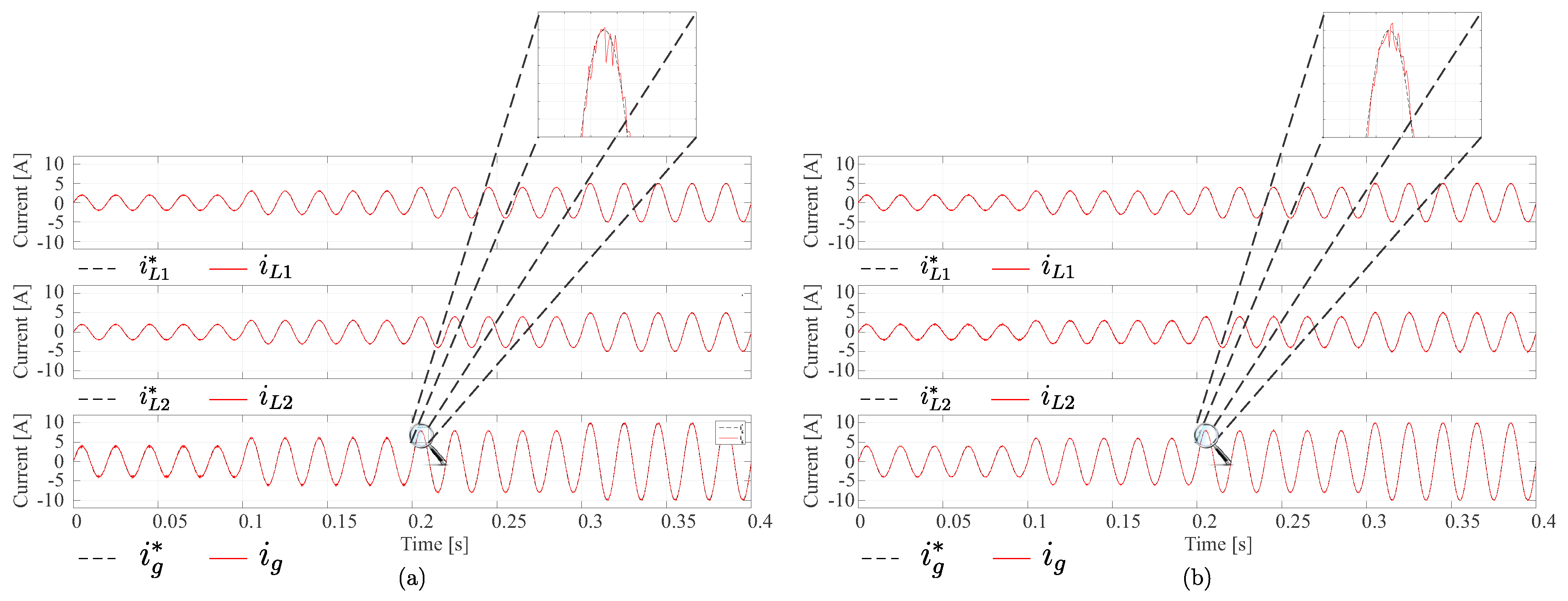
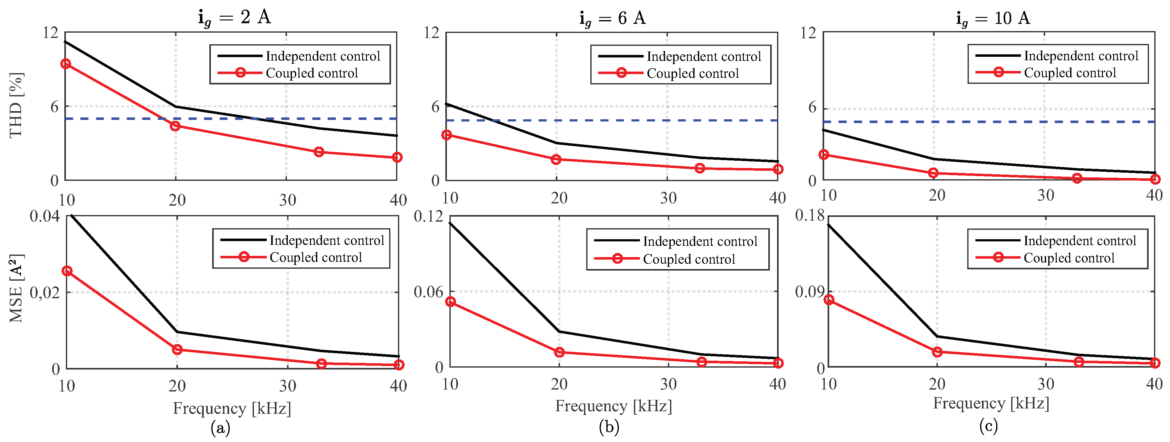
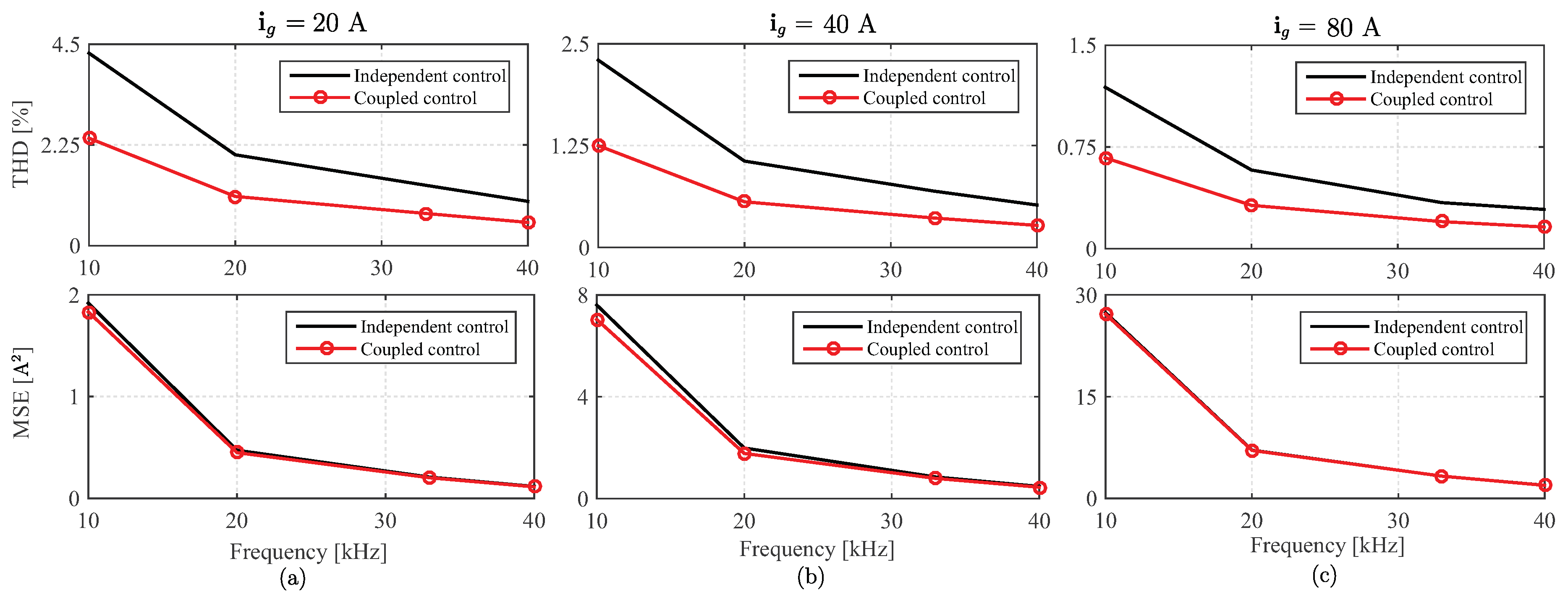
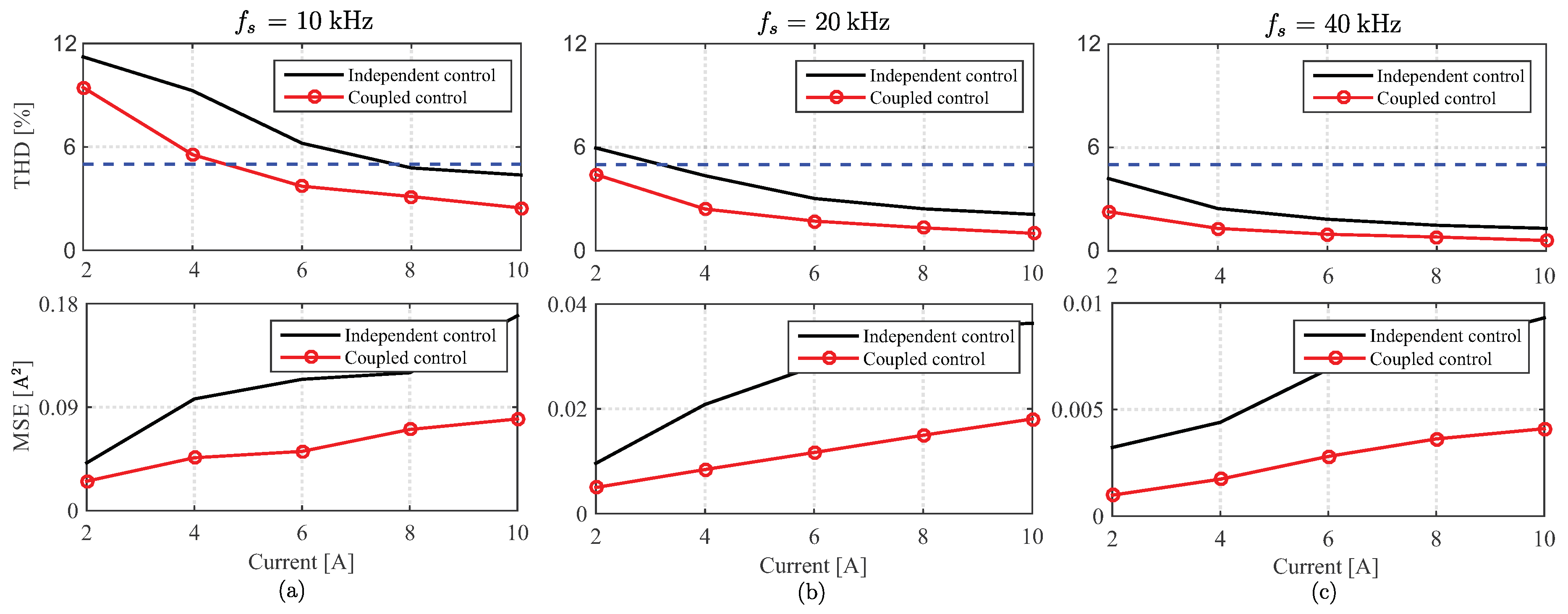
4. Simulation and Analysis of the Technique

The proposed control strategy was simulated in the Matlab/Simulink environment. The chosen system parameters are shown in Table 1. These parameters have been selected according to the availability in the laboratory in order to validate the obtained simulation results by experiments. Several operating points are considered to develop the performance analysis. In Figure 3, the response for a series of steps from 2 to 10 A are shown at a sampling frequency of 20 kHz to observe the behavior for low load currents. Figure 3a shows the independent control response, whereas Figure 3b the same for the proposed coupled control. In Figure 4 the response from 20 to 80 A are shown to verify the behavior for high operating points both for the classic approach as for the coupled control where V s = 220  V and R = 0.1 Ω have been chosen to achieve these load values. Note that both techniques can correctly follow the reference, but the proposal seems to decrease the peaks of the variations around the reference in all cases. In order to quantify the improvement, two comparisons were carried out. In  Figure 5 the variation of THD and MSE in terms of sampling frequency for different operating points are shown. Figure 6 shows the same of the previous but for higher load currents to depict the behavior of the proposal at these values of reference. The sampling frequencies were chosen based on the experimental feasible values in 10 kHz, 20 kHz, 33 kHz and 40 kHz. These figures shown that the proposed method was always better in terms of the target parameters compared with the independent control for both low and high currents. In THD curve (i.e., upper row) the line of 5% is shown in a blue line to indicate whether the international requirement is accomplished in each case [31]. For example, at 10 A the requirement is always achieved but for 6 A only the coupled technique complies with the maximum THD for 10 kHz. As expected on predictive control techniques theory, both implementations show improvement as sampling frequency increases. In Figure 7 the variation on THD and MSE are illustrated in terms of load current. As it can be noted, for 40 kHz it is possible to control all the values of current with low MSE and acceptable THD. Furthermore, the proposal accomplishes with this even with 20 kHz mean while a decoupled implementation cannot in low currents. Regarding the THD and considering all the three-phase currents, the improvement was around 15% (i.e., worst case) to 55% (i.e., best case). In terms of MSE, the improvement was around 41% to 60% in phase a (i.e., the best case), but only around 3% to 26% in phase c (i.e., worst case) for low currents. For higher load currents (i.e., more than 20 A), the MSE difference decreases and is almost the same in both implementations. However, regarding THD the improvement stays around 50 %. The next section shows the experimental results obtained using a multi-modular SiC-MOSFET based MC with two three-phase converters and six-phase input.

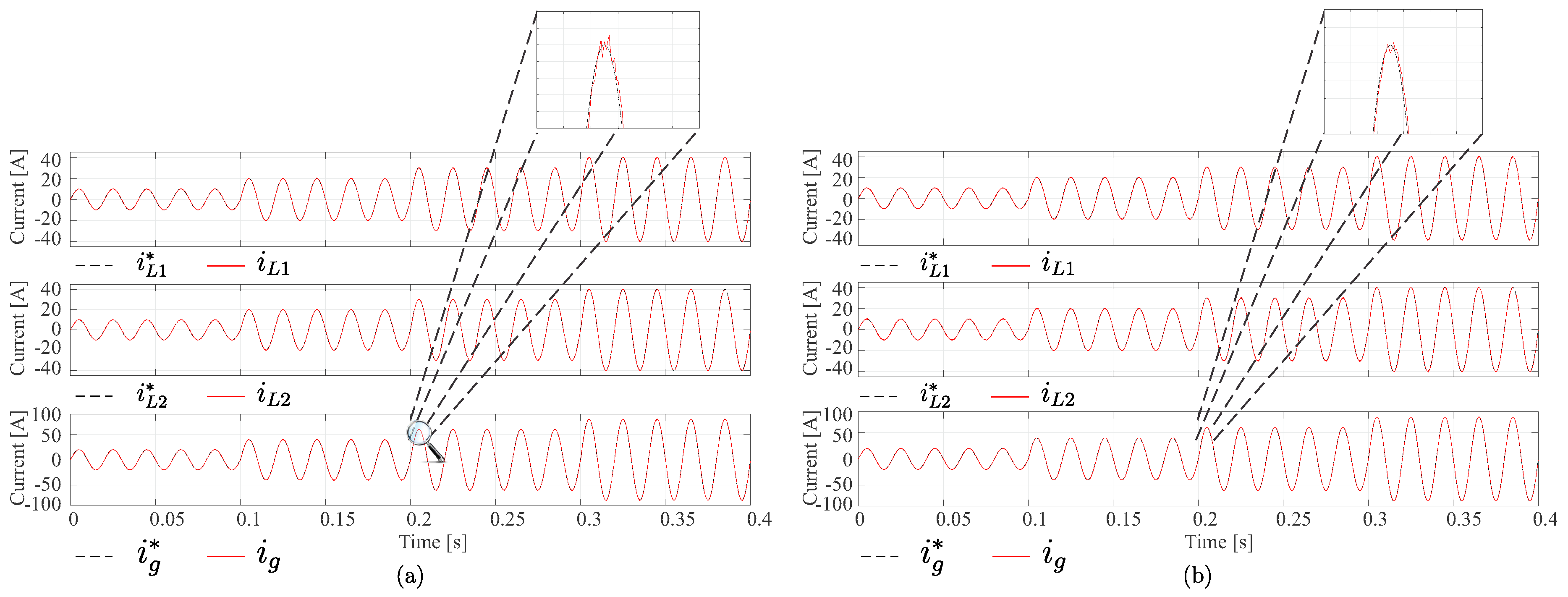
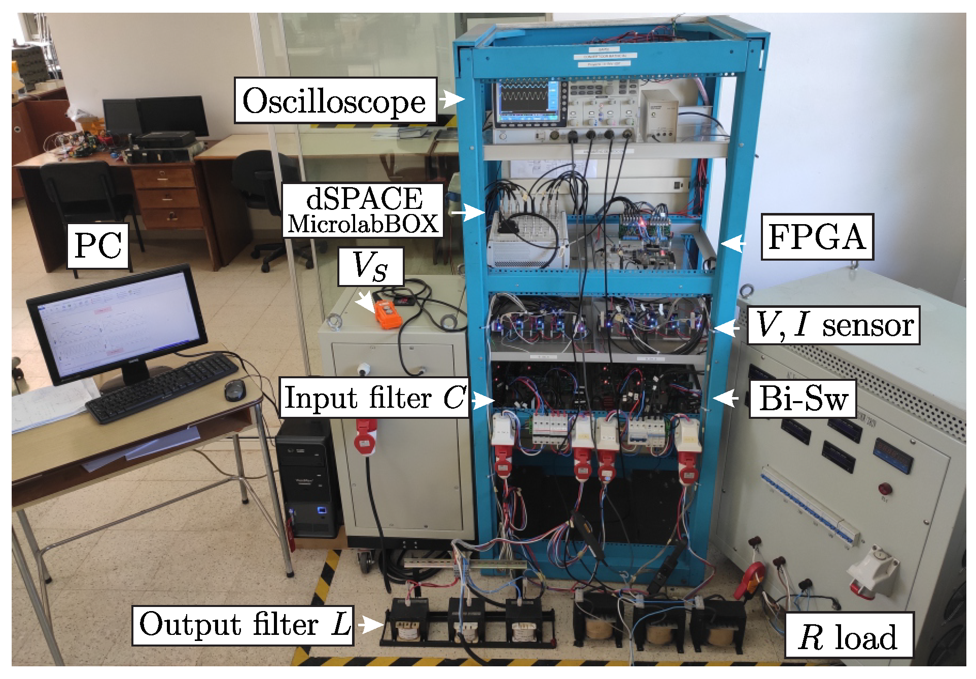
5. Experimental Validation

In order to validate the improvement of the proposed technique, an experimental setup has been assembled as is shown in Figure 8. The MC in this bench is based on the bidirectional switches described and designed in [32].
The control uses a MicroLabBox dSPACE and a Nexys 3 FPGA. The predictive control strategy is implemented in the dSPACE. The FPGA oversees the timing, the application of the four-step current commutation strategy [33], the safety operation and devices protection. The values of the electrical parameters are the same as previous simulations and represented in Table 1. In this case, the six-phase signal was generated with two three-phase generators connected to the input of the multi-modular converter. The implemented algorithms are shown in Appendix A. It is important to note that the implementation has one sampling time delay since it takes measured values in t 0 and calculated the optimal vector in this time, but the vector is applied in t 0 + T s . Therefore the implementation of a predictive control technique with two steps horizon is used as can be observed in the presented algorithms. In this context, Appendix A.1 consists of the typical predictive current control with independent module control and Appendix A.2 is the improved technique using a coupling between the control of the modules.
Figure 9 shows the oscilloscope measured currents for the proposed control technique, where  i L 1 is the current in module 1 following 0.5 i g * , i L 2 is the module 2 current, following 0.5 i g * plus the predicted error in module 1. It can be noted that the total supplied current has a good tracking of the reference, but the currents of each module are different. The experimental results have been extracted with calibrated instrumentation equipment. THD and MSE were used as parameters to analyze the advantages of the proposed method. The first one considered as a performance parameter to observe the improvement of the proposed MPC variation, was obtained by taking 25,000 measurements of the signal with which the THD value was calculated, this process was performed 10 times, and finally the arithmetic mean of these 10 values was obtained, this is done for each analyzed scenario. On the other hand, the MSE, is used as a parameter for the analysis of experimental results in terms of error that the algorithm throws, integrating the proposed control with the drive, measurement and load modules. The arithmetic mean of a set of sample means of the MSE was calculated, since this is the best estimate of the population mean. The results of THD and MSE are shown in two figures. Here is important to mention that compared with simulation environment, experiments include the effects of the induced electrical noise due to the increase on the sampling frequency, that is expected in switched systems implementation. This issue can be diminished enhancing the shielding in wires and in the power stage. The measurement stage shows typical noise levels associated to this kind of applications. Due to these noises it is expected that the experimental results present higher levels in the target parameters than simulations. However, considering these error sources, the main aim in the experimental setup consist of shows the improvement of the proposal and, considering that the error introduced is the same in both techniques, the difference is the control strategy and the results allows to validate the phenomenon. Figure 10 shows how the improvement is achieved experimentally for all the considered sampling frequencies at different load currents in terms of THD and MSE reduction. Figure 11 shows the behavior for various operating points at the same sampling frequency. The experimental results allow to see that the proposal improves the performance of the predictive control reducing the THD and the MSE in all the analyzed cases.

6. Conclusions

Summarizing the proposal features it is possible to mention that the main strengths are (i) the power conversion stage do not needs energy storage elements which results in less weight and size compared with AC-DC-AC topologies, (ii) the control provides fast transient response with suitable error and THD levels, (iii) the coupling signal allows to reduce error and THD improving the performance of the conversion stage compared with the classical MPC current control and, finally, (iv) the control strategy is very simply to implement and understand, making it versatile and easy to adequate whether other control target is required. The proposal presents some weaknesses inherit the MPC techniques compared with modulation techniques as variable switching frequency that may increase the noise due to the resonances in the filters if they are not well designed. However, this issue can be solved using a modulated predictive control strategy to mitigate the variable switching frequency problem. Considering the proposal, the computational burden increases compared with classic MPC but thanks to the high capability of nowadays microcontrollers the increment is negligible. From the simulation and the experimental tests it can be evidenced that the proposal variation of the cost function and the implementation of the predictive control achieve an improvement in the performance of the controller, reducing the THD and the MSE for several operating points and different sampling frequencies. The technique has good tracking and allows use lower sampling frequencies and extend the operating range of the controller. In this case the fact of having two converters interacting among themselves has been exploited to increase the performance of the technique and the same idea can be extended to another topologies and even improved modifying the cost function of the first module considering the error of the second. Given the improvement in supplied electrical current quality, the main contribution of the proposal consists of a new approach based on predictive control that noticeable reduces THD and error, suitable for any multi-phase generation system that uses more than one converter module. This can be the beginning of a series of proposals that can consider this coupling, extending the implementation of the strategy to other multi-modular topologies in varied applications.

Author Contributions

Conceptualization, S.T., M.R., R.G. and P.W.; Data curation, S.T. and M.R.; Formal analysis, S.T., E.M., M.R. and C.R.; Funding acquisition, S.T. and R.G.; Investigation, S.T.; Methodology, S.T. and E.M.; Project administration, M.R. and R.G.; Resources, M.R., R.G. and P.W.; Software, S.T.; Supervision, M.R., R.G. and P.W.; Validation, S.T., E.M. and C.R.; Visualization, E.M. and C.R.; Writing—original draft, S.T. and E.M.; Writing—review & editing, M.R., R.G., P.W. and C.R. All authors have read and agreed to the published version of the manuscript.

Funding

This research was funded by Consejo Nacional de Ciencia y Tecnología de Paraguay (CONACYT), for the support and financing through Project PINV15-0584, CONICYT of Chile through the FONDECYT Regular Project 1160690, Project MEC 80150056 and the grant CONICYT-PFCHA/Doctorado Nacional/2019-21192003.

Conflicts of Interest

The authors declare no conflict of interest.

Appendix A. Predictive Current Control Algorithms for the Multi-Modular Matrix Converter Topology

Appendix A.1. Independent Predictive Current Control

Algorithm 1 Independent predictive current control
1. Initialize g 1 o p t : = , g 2 o p t : = , v o 1 o p t : = 0 , v o 2 o p t : = 0
2. Read measured v i 1 , v i 2 , i L 1 , i L 2 , v g
3. Compute predicted i L 1 k + 1 and i L 2 k + 1 using v o 1 o p t and v o 2 o p t in Equation (7)
4. for j=1 to 27
5.      Compute v o 1 and v o 2 using S j (Equation (2))
6.      Compute the prediction of i L 1 k + 2 and i L 2 k + 2 using i L 1 k + 1 and i L 2 k + 1 calculation in Equation (7)
7.      Compute the cost functions g 1 and g 2 (Equation (9))
8.      if g 1 < g 1 o p t then
9.         g 1 o p t g 1 , S 1 o p t S j , v o 1 o p t v o 1
10.     end if
11.      if g 2 < g 2 o p t then
12.         g 2 o p t g 2 , S 2 o p t S j , v o 2 o p t v o 2
13.     end if
14. end for
15. Apply the optimum vector S o p t { S 1 o p t , S 2 o p t }

Appendix A.2. Coupled Predictive Current Control

Algorithm 2 Coupled predictive current control
1. Initialize g 1 o p t : = , g 2 o p t : = , v o 1 o p t : = 0 , v o 2 o p t : = 0
2. Read measured v i 1 , v i 2 , i L 1 , i L 2 , v g
3. Compute predicted i L 1 k + 1 and i L 2 k + 1 using v o 1 o p t and v o 2 o p t in Equation (7)
4. for j=1 to 27
5.      Compute v o 1 using S j (Equation (2))
6.      Compute the prediction of i L 1 k + 2 using i L 1 k + 1 calculation in Equation (7)
7.      Compute the cost function g 1 (Equation (11))
8.      if g 1 < g 1 o p t then
9.         g 1 o p t g 1 , S 1 o p t S j , v o 1 o p t v o 1 , e p ( i L 1 * i L 1 k + 2 )
10.     end if
11. end for
12. for j=1 to 27
13.      Compute v o 2 using S j (Equation (2))
14.      Compute the prediction of i L 2 k + 2 using i L 2 k + 1 calculation in Equation (7)
15.      Compute the cost function g 2 (Equation (11))
16.      if g 2 < g 2 o p t then
17.         g 2 o p t g 2 , S 2 o p t S j , v o 2 o p t v o 2
18.     end if
19. end for
20. Apply the optimum vector S o p t { S 1 o p t , S 2 o p t }

References

  1. Smil, V. Distributed Generation and Megacities: Are Renewables the Answer? IEEE Power Energy Mag. 2019, 17, 37–41. [Google Scholar] [CrossRef]
  2. Ahmed, S.D.; Al-Ismail, F.S.M.; Shafiullah, M.; Al-Sulaiman, F.A.; El-Amin, I.M. Grid Integration Challenges of Wind Energy: A Review. IEEE Access 2020, 8, 10857–10878. [Google Scholar] [CrossRef]
  3. Toledo, S.; Rivera, M.; Elizondo, J.L. Overview of wind energy conversion systems development, technologies and power electronics research trends. In Proceedings of the 2016 IEEE International Conference on Automatica (ICA-ACCA), Curico, Chile, 19–21 October 2016; pp. 1–6. [Google Scholar] [CrossRef]
  4. Duran, M.J.; Barrero, F. Recent Advances in the Design, Modeling, and Control of Multiphase Machines: Part II. IEEE Trans. Ind. Electron. 2016, 63, 459–468. [Google Scholar] [CrossRef]
  5. Chinmaya, K.; Singh, G.K. Performance evaluation of multiphase induction generator in stand-alone and grid-connected wind energy conversion system. IET Renew. Power Gener. 2018, 12, 823–831. [Google Scholar] [CrossRef]
  6. Gonzalez, O.; Ayala, M.; Doval-Gandoy, J.; Rodas, J.; Gregor, R.; Rivera, M. Predictive-Fixed Switching Current Control Strategy Applied to Six-Phase Induction Machine. Energies 2019, 12, 2294. [Google Scholar] [CrossRef] [Green Version]
  7. Liu, Z.; Li, Y.; Zheng, Z. A review of drive techniques for multiphase machines. CES Trans. Electr. Mach. Syst. 2018, 2, 243–251. [Google Scholar] [CrossRef]
  8. Barrero, F.; Duran, M.J. Recent Advances in the Design, Modeling, and Control of Multiphase Machines: Part I. IEEE Trans. Ind. Electron. 2016, 63, 449–458. [Google Scholar] [CrossRef]
  9. Priya, M.; Ponnambalam, P.; Muralikumar, K. Modular-multilevel converter topologies and applications—A review. IET Power Electron. 2019, 12, 170–183. [Google Scholar] [CrossRef]
  10. Salgado-Herrera, N.; Campos-Gaona, D.; Anaya-Lara, O.; Medina-Rios, A.; Tapia-Sánchez, R.; Rodríguez-Rodríguez, J. THD reduction in wind energy system using type-4 Wind Turbine/PMSG applying the active front-end converter parallel operation. Energies 2018, 11, 2458. [Google Scholar] [CrossRef] [Green Version]
  11. Bakas, P.; Harnefors, L.; Norrga, S.; Nami, A.; Ilves, K.; Dijkhuizen, F.; Nee, H. A Review of Hybrid Topologies Combining Line-Commutated and Cascaded Full-Bridge Converters. IEEE Trans. Power Electron. 2017, 32, 7435–7448. [Google Scholar] [CrossRef]
  12. Feng, Z.; Zhang, X.; Wang, J.; Yu, S. A High-Efficiency Three-Level ANPC Inverter Based on Hybrid SiC and Si Devices. Energies 2020, 13, 1159. [Google Scholar] [CrossRef] [Green Version]
  13. Li, J.; Konstantinou, G.; Wickramasinghe, H.R.; Pou, J. Operation and Control Methods of Modular Multilevel Converters in Unbalanced AC Grids: A Review. IEEE J. Emerg. Sel. Top. Power Electron. 2019, 7, 1258–1271. [Google Scholar] [CrossRef]
  14. Zhang, J.; Li, L.; Dorrell, D.G. Control and applications of direct matrix converters: A review. Chin. J. Electr. Eng. 2018, 4, 18–27. [Google Scholar] [CrossRef]
  15. Riveros, J.A.; Prieto, J.; Rivera, M.; Toledo, S.; Gregor, R. A generalised multifrequency PWM strategy for dual three-phase voltage source converters. Energies 2019, 12, 1398. [Google Scholar] [CrossRef] [Green Version]
  16. Dragicevic, T.; Zheng, C.; Rodriguez, J.; Blaabjerg, F. Robust Quasi-Predictive Control of LCL-Filtered Grid Converters. IEEE Trans. Power Electron. 2019. [Google Scholar] [CrossRef]
  17. Rivera, M.; Toledo, S.; Tarisciotti, L.; Wheeler, P.W.; Dan, H. Predictive Control Strategies Operating at Fixed Switching Frequency for Input Filter Resonance Mitigation in an Indirect Matrix Converter. IEEE Lat. Am. Trans. 2018, 16, 2370–2376. [Google Scholar] [CrossRef]
  18. Li, H.; Ren, K.; Li, S.; Dong, H. Adaptive Multi-Model Switching Predictive Active Power Control Scheme for Wind Generator System. Energies 2020, 13, 1329. [Google Scholar] [CrossRef] [Green Version]
  19. Gontijo, G.F.; Tricarico, T.C.; França, B.W.; da Silva, L.F.; van Emmerik, E.L.; Aredes, M. Robust Model Predictive Rotor Current Control of a DFIG Connected to a Distorted and Unbalanced Grid Driven by a Direct Matrix Converter. IEEE Trans. Sustain. Energy 2019, 10, 1380–1392. [Google Scholar] [CrossRef]
  20. Vijayagopal, M.; Silva, C.; Empringham, L.; de Lillo, L. Direct Predictive Current-Error Vector Control for a Direct Matrix Converter. IEEE Trans. Power Electron. 2019, 34, 1925–1935. [Google Scholar] [CrossRef]
  21. Zhang, J.; Li, L.; Dorrell, D.G.; Norambuena, M.; Rodriguez, J. Predictive Voltage Control of Direct Matrix Converters With Improved Output Voltage for Renewable Distributed Generation. IEEE J. Emerg. Sel. Top. Power Electron. 2019, 7, 296–308. [Google Scholar] [CrossRef]
  22. Formentini, A.; Trentin, A.; Marchesoni, M.; Zanchetta, P.; Wheeler, P. Speed Finite Control Set Model Predictive Control of a PMSM Fed by Matrix Converter. IEEE Trans. Ind. Electron. 2015, 62, 6786–6796. [Google Scholar] [CrossRef]
  23. Siami, M.; Amiri, M.; Savadkoohi, H.K.; Rezavandi, R.; Valipour, S. Simplified Predictive Torque Control for a PMSM Drive Fed by a Matrix Converter With Imposed Input Current. IEEE J. Emerg. Sel. Top. Power Electron. 2018, 6, 1641–1649. [Google Scholar] [CrossRef]
  24. Lei, J.; Feng, S.; Wheeler, P.; Zhou, B.; Zhao, J. Steady-State Error Suppression and Simplified Implementation of Direct Source Current Control for Matrix Converter With Model Predictive Control. IEEE Trans. Power Electron. 2020, 35, 3183–3194. [Google Scholar] [CrossRef]
  25. Toledo, S.; Rivera, M.; Gregor, R.; Rodas, J.; Comparatore, L. Predictive current control with reactive power minimization in six-phase wind energy generator using multi-modular direct matrix converter. In Proceedings of the 2016 IEEE ANDESCON, Arequipa, Peru, 19–21 October 2016; pp. 1–4. [Google Scholar] [CrossRef]
  26. Toledo, S.; Gregor, R.; Rivera, M.; Rodas, J.; Gregor, D.; Caballero, D.; Gavilán, F.; Maqueda, E. Multi-modular matrix converter topology applied to distributed generation systems. In Proceedings of the 8th IET International Conference on Power Electronics, Machines and Drives (PEMD 2016), Glasgow, UK, 19–21 April 2016; pp. 1–6. [Google Scholar] [CrossRef]
  27. Khosravi, M.; Amirbande, M.; Khaburi, D.A.; Rivera, M.; Riveros, J.; Rodriguez, J.; Vahedi, A.; Wheeler, P. Review of model predictive control strategies for matrix converters. IET Power Electron. 2019, 12, 3021–3032. [Google Scholar] [CrossRef]
  28. Gontijo, G.; Soares, M.; Tricarico, T.; Dias, R.; Aredes, M.; Guerrero, J. Direct Matrix Converter Topologies with Model Predictive Current Control Applied as Power Interfaces in AC, DC, and Hybrid Microgrids in Islanded and Grid-Connected Modes. Energies 2019, 12, 3302. [Google Scholar] [CrossRef] [Green Version]
  29. Gonçalves, P.; Cruz, S.; Mendes, A. Finite Control Set Model Predictive Control of Six-Phase Asymmetrical Machines—An Overview. Energies 2019, 12, 4693. [Google Scholar] [CrossRef] [Green Version]
  30. O’Rourke, C.J.; Qasim, M.M.; Overlin, M.R.; Kirtley, J.L. A Geometric Interpretation of Reference Frames and Transformations: Dq0, Clarke, and Park. IEEE Trans. Energy Convers. 2019, 34, 2070–2083. [Google Scholar] [CrossRef] [Green Version]
  31. IEEE. IEEE Recommended Practice and Requirements for Harmonic Control in Electric Power Systems. In IEEE Std 519-2014 (Revision of IEEE Std 519-1992); IEEE: Piscataway, NJ, USA, 2014; pp. 1–29. [Google Scholar] [CrossRef]
  32. Maqueda, E.; Rodas, J.; Toledo, S.; Gregor, R.; Caballero, D.; Gavilan, F.; Rivera, M. Design and implementation of a modular bidirectional switch using SiC-MOSFET for power converter applications. Act. Passiv. Electron. Components 2018, 2018. [Google Scholar] [CrossRef] [Green Version]
  33. Wheeler, P.W.; Clare, J.; Empringham, L. Enhancement of matrix converter output waveform quality using minimized commutation times. IEEE Trans. Ind. Electron. 2004, 51, 240–244. [Google Scholar] [CrossRef]
Figure 1. Proposed control scheme for SpWEG.
Energies 13 02660 g001
Figure 2. Topology of the direct matrix converter module with filters.
Energies 13 02660 g002
Figure 3. Tracking performance for different desired current from 2 to 10 A. (a) Independent output current control. (b) Proposed coupled output current control.
Energies 13 02660 g003
Figure 4. Tracking performance for different desired current from 20 to 80 A. (a) Independent output current control. (b) Proposed coupled output current control.
Energies 13 02660 g004
Figure 5. THD and MSE curves according to changes in switching frequency with fixed load. (a) For 2 A. (b) for 6 A and (c) for 10 A.
Energies 13 02660 g005
Figure 6. THD and MSE curves according to changes in switching frequency with fixed load. (a) For 20 A. (b) for 40 A and (c) for 80 A.
Energies 13 02660 g006
Figure 7. THD and MSE curves according to changes in the load with fixed frequency. (a) f s = 10 kHz. (b) f s = 20 kHz and (c) f s = 40 kHz.
Energies 13 02660 g007
Figure 8. Experimental setup.
Energies 13 02660 g008
Figure 9. Output current waveforms with coupled control.
Energies 13 02660 g009
Figure 10. Experimental performance of THD and MSE curves according to changes in switching frequency with fixed load. (a) For 2 A. (b) for 6 A and (c) for 10 A.
Energies 13 02660 g010
Figure 11. Experimental performance of THD and MSE according to changes in the load with fixed frequency. (a) f s = 10 kHz. (b) f s = 20 kHz and (c) f s = 40 kHz.
Energies 13 02660 g011
Table 1. Electrical parameters used in the topology.
DescriptionElectrical Parameters
SymbolValueUnit
Generator phase peak voltage V s 110-220V
Generator frequency f s 50Hz
Input filter capacitance C f 11 μ F
Output filter leakage resistance R f o 0.3 Ω
Output filter inductance L f o 10mH
Load resistanceR5.3-0.1 Ω

