Solar PV Sustained Quasi Z-Source Network-Based Unified Power Quality Conditioner for Enhancement of Power Quality


Abstract
:1. Introduction
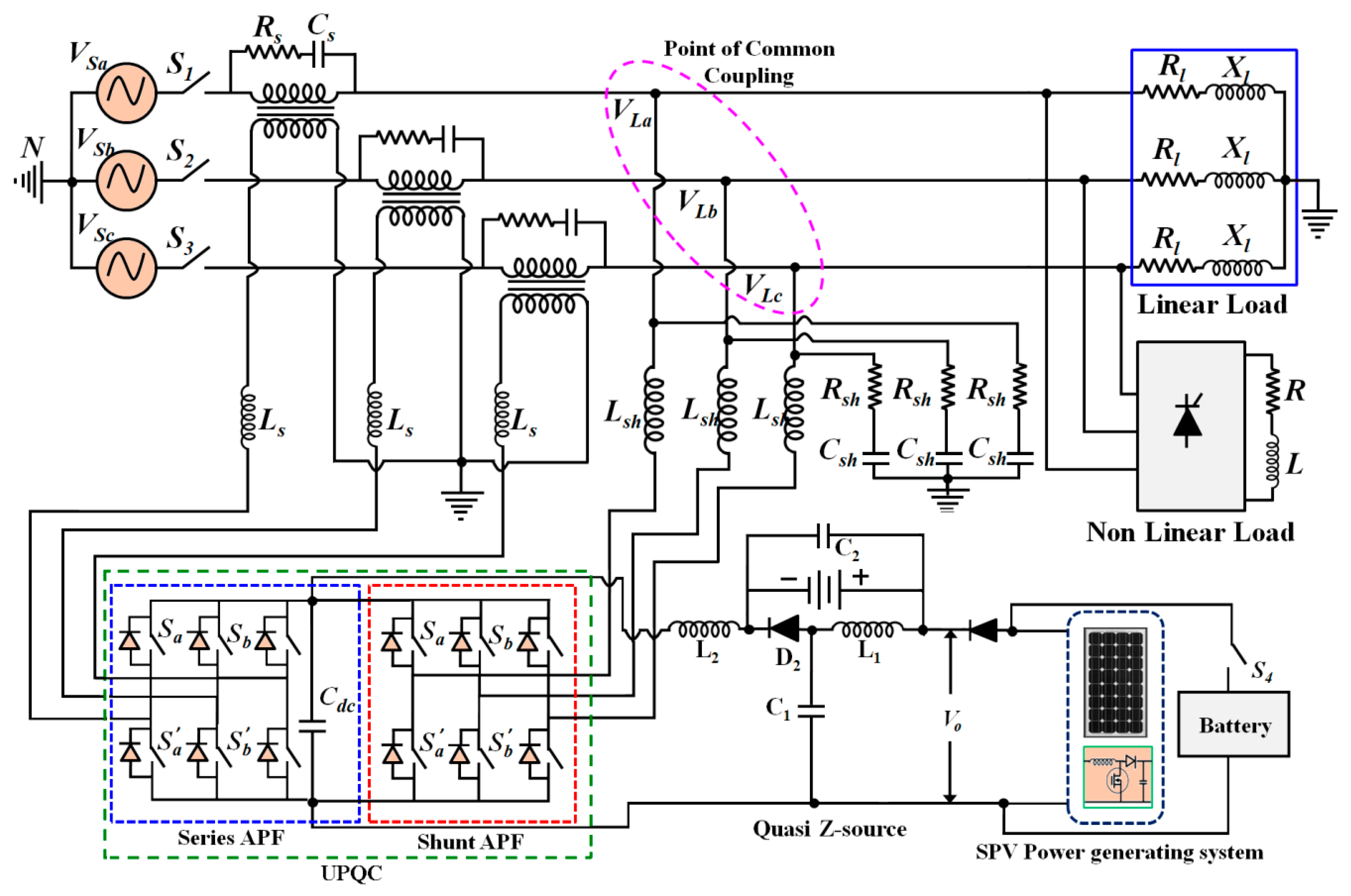
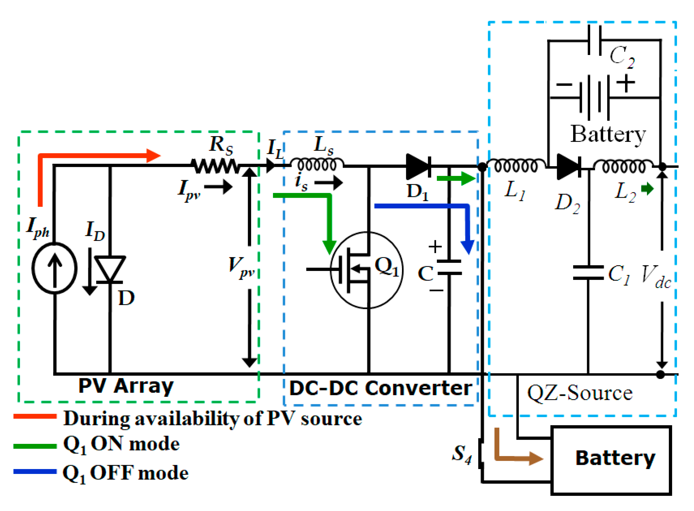
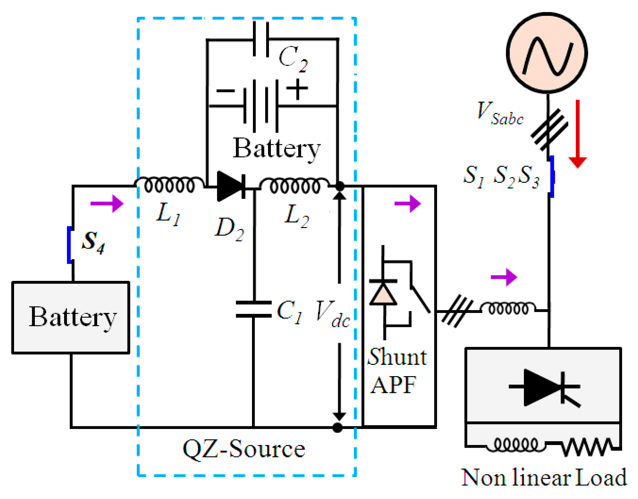
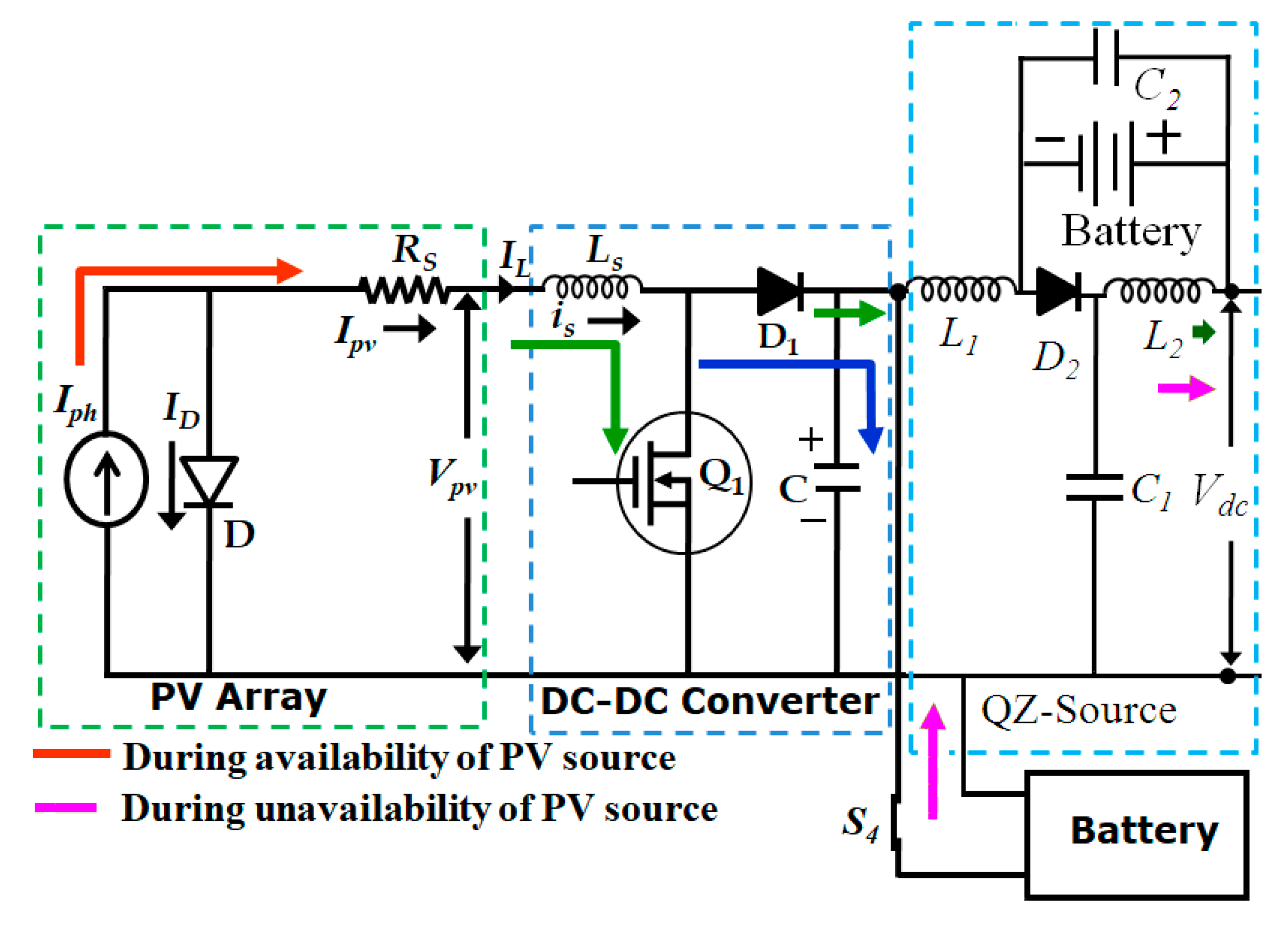
2. QZ-source Network-Based UPQC Topology
3. SPV-UPQC Control Scheme
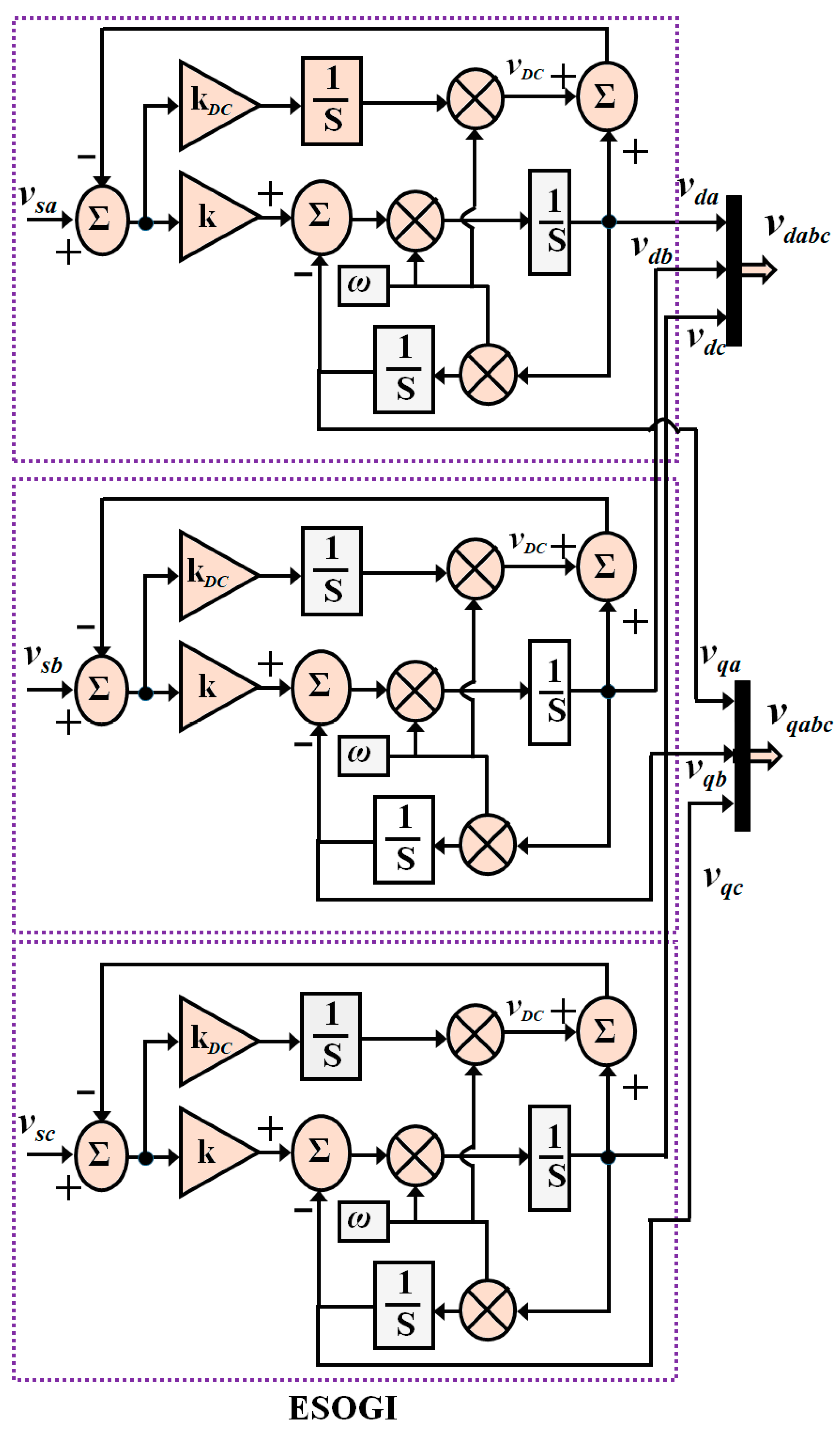
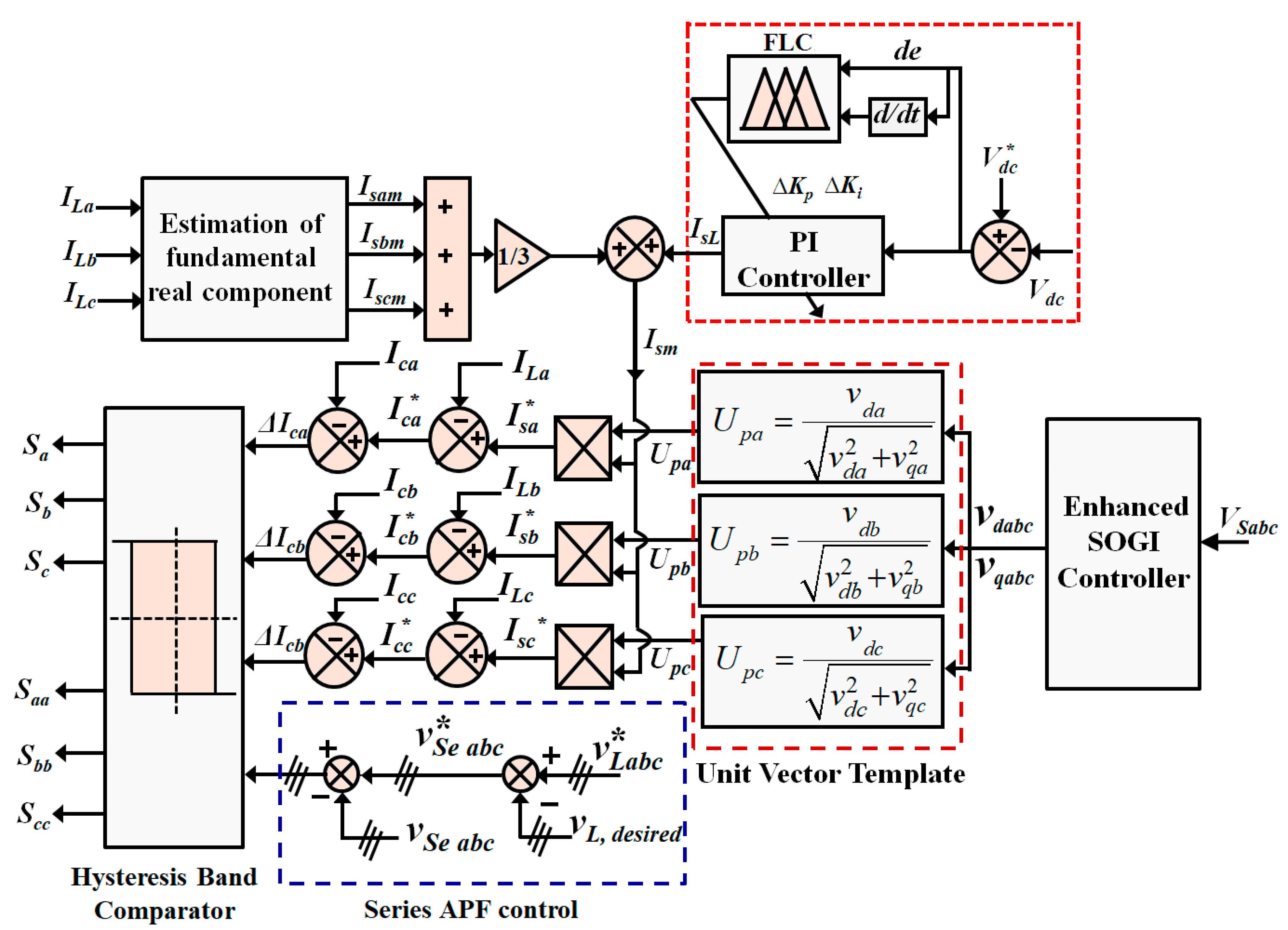
3.1. Extraction of Fundamental Component
3.2. Estimation Source Reference Current for Shunt APFs
3.3. Estimation of Reference Voltages for Series APFs
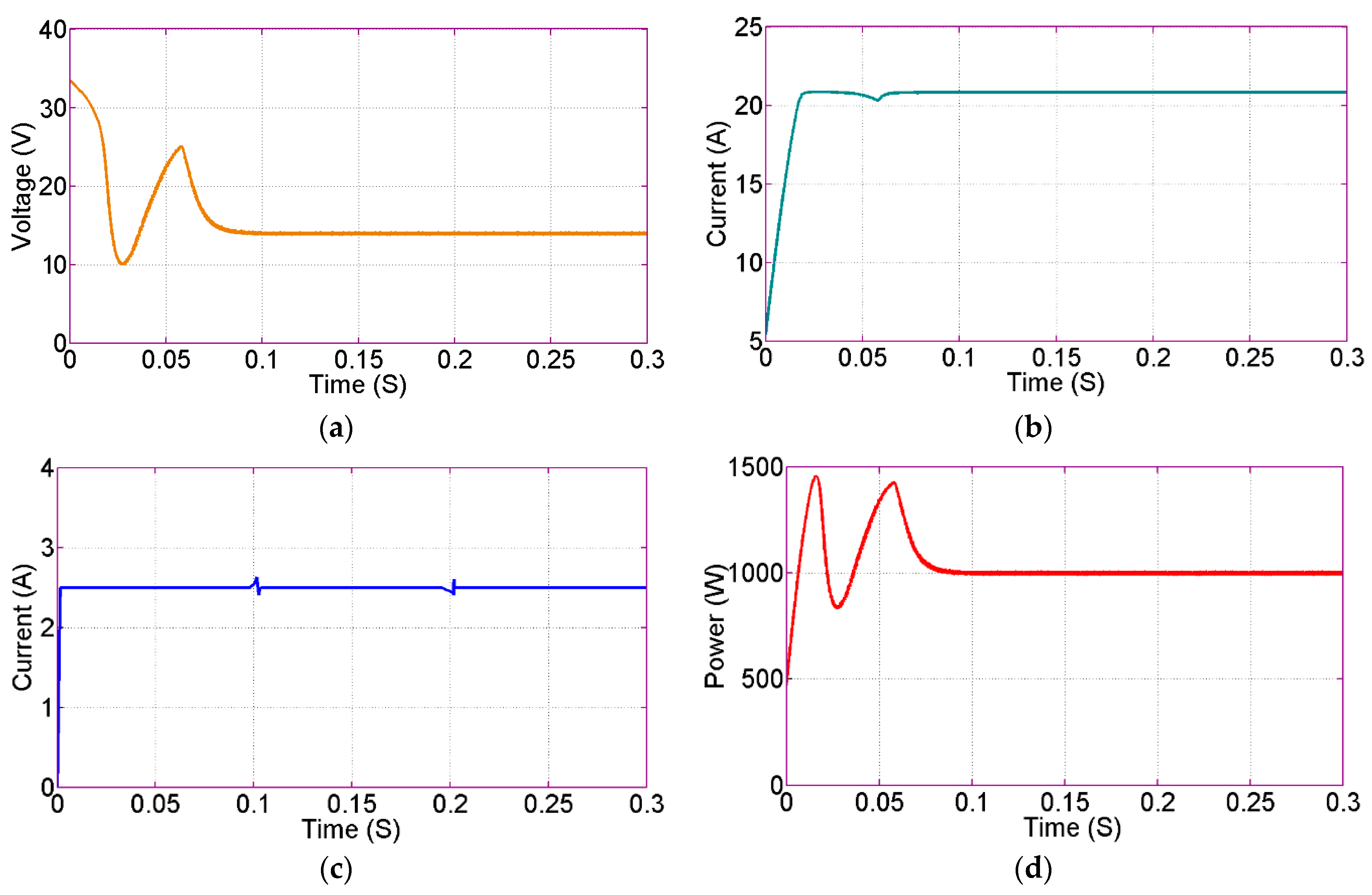
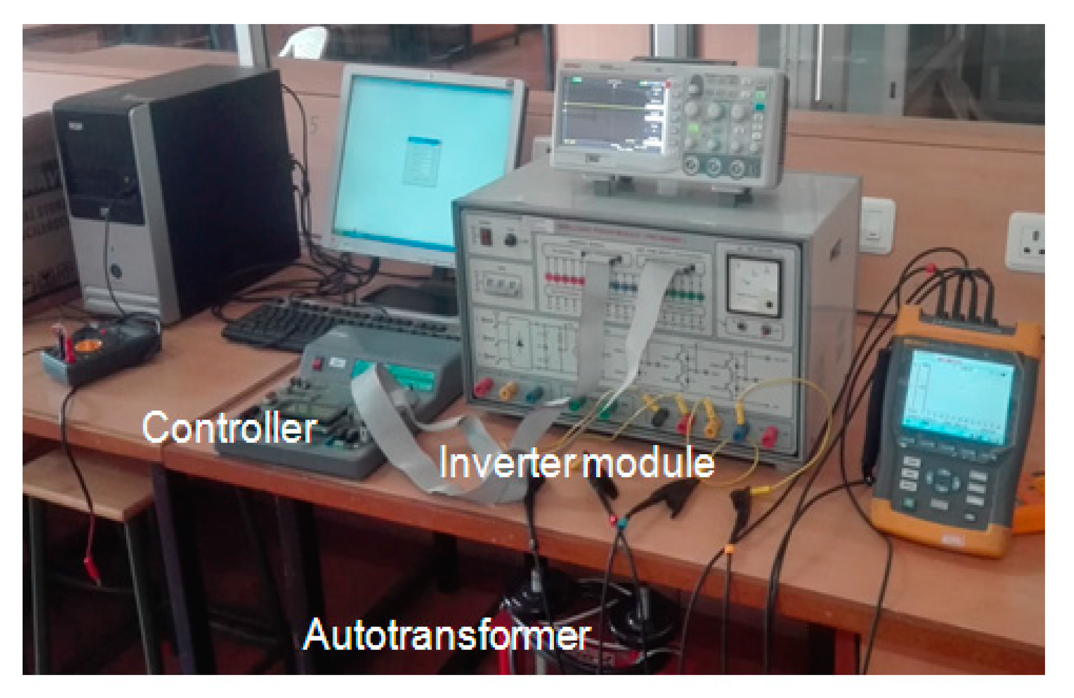
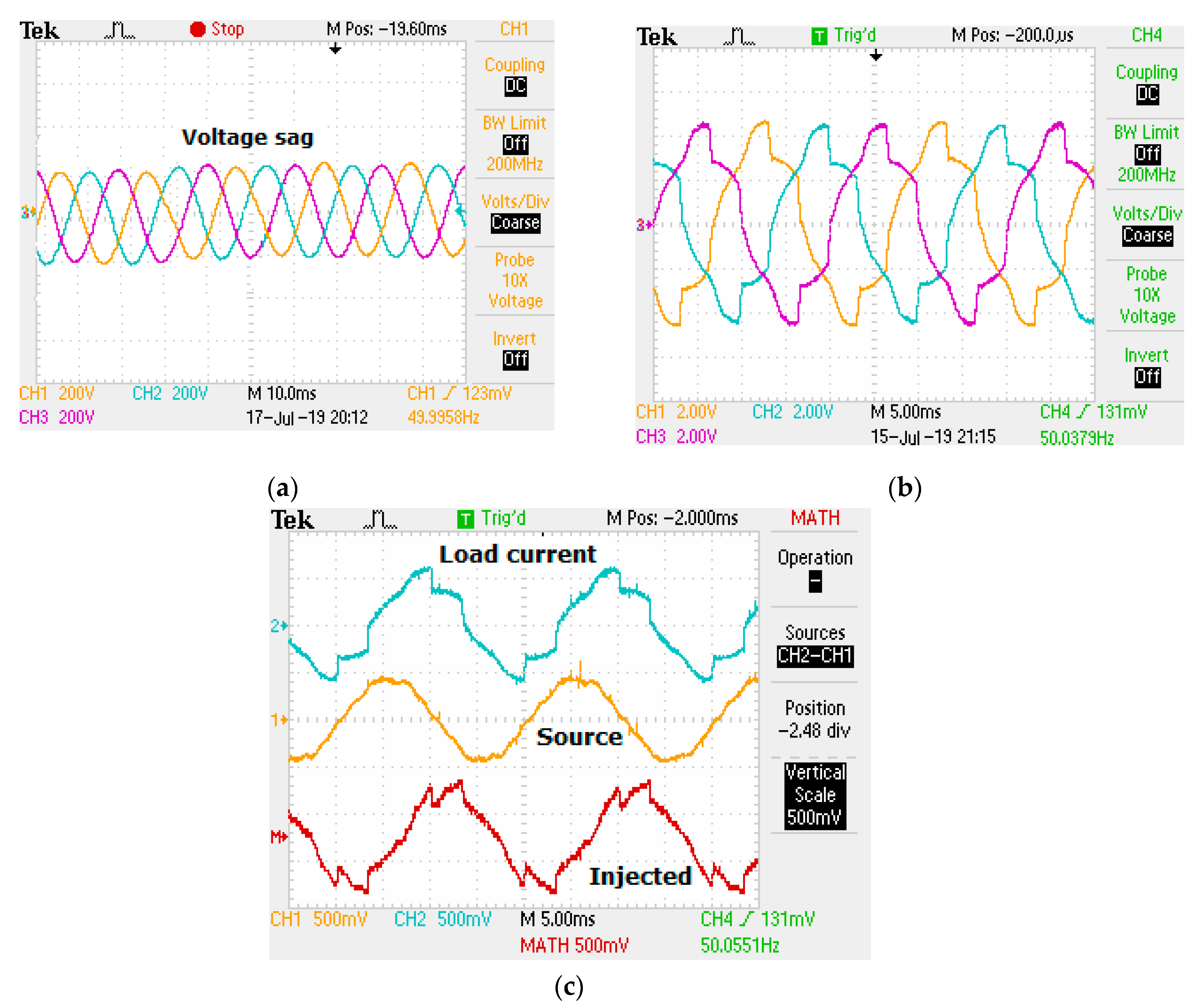
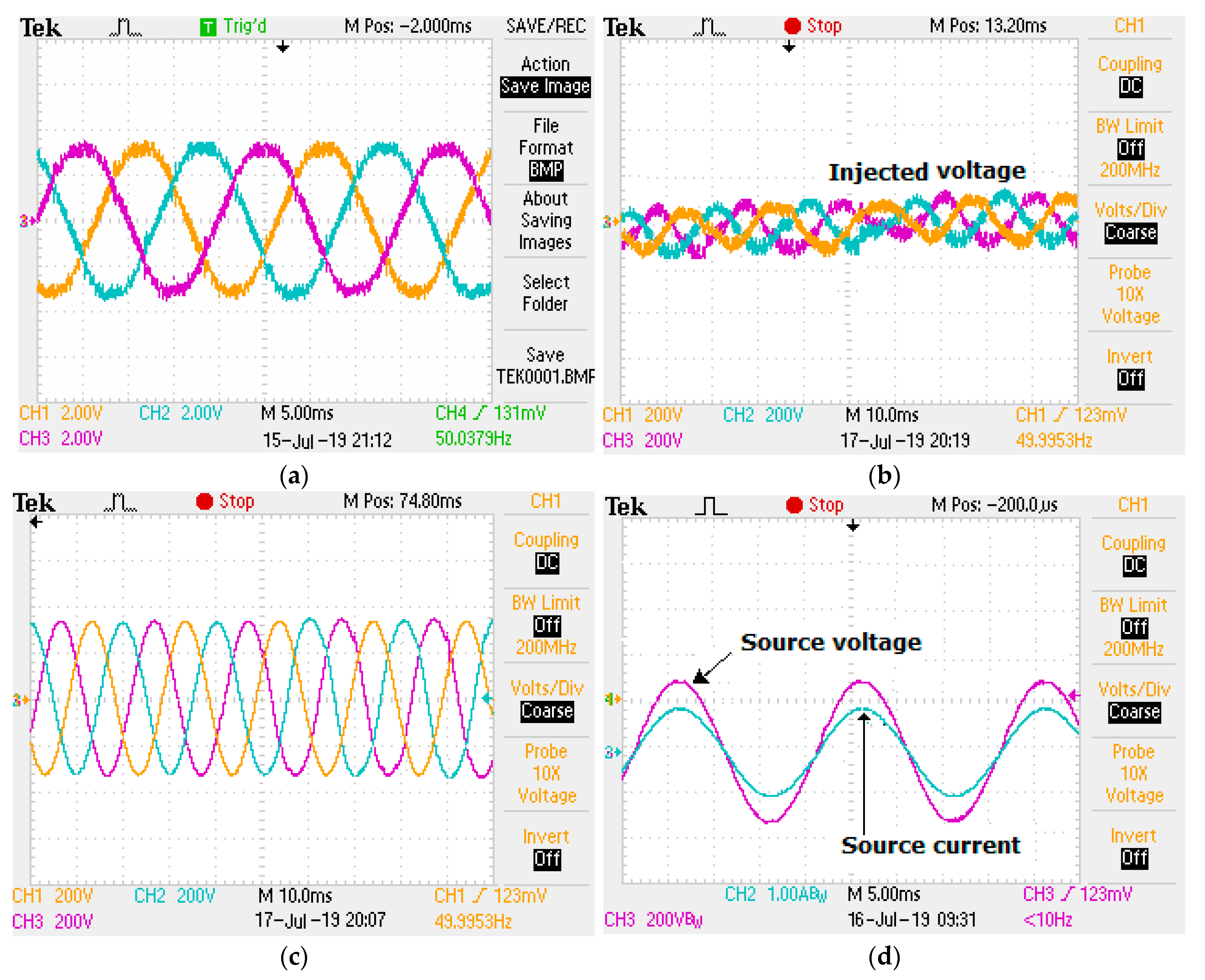
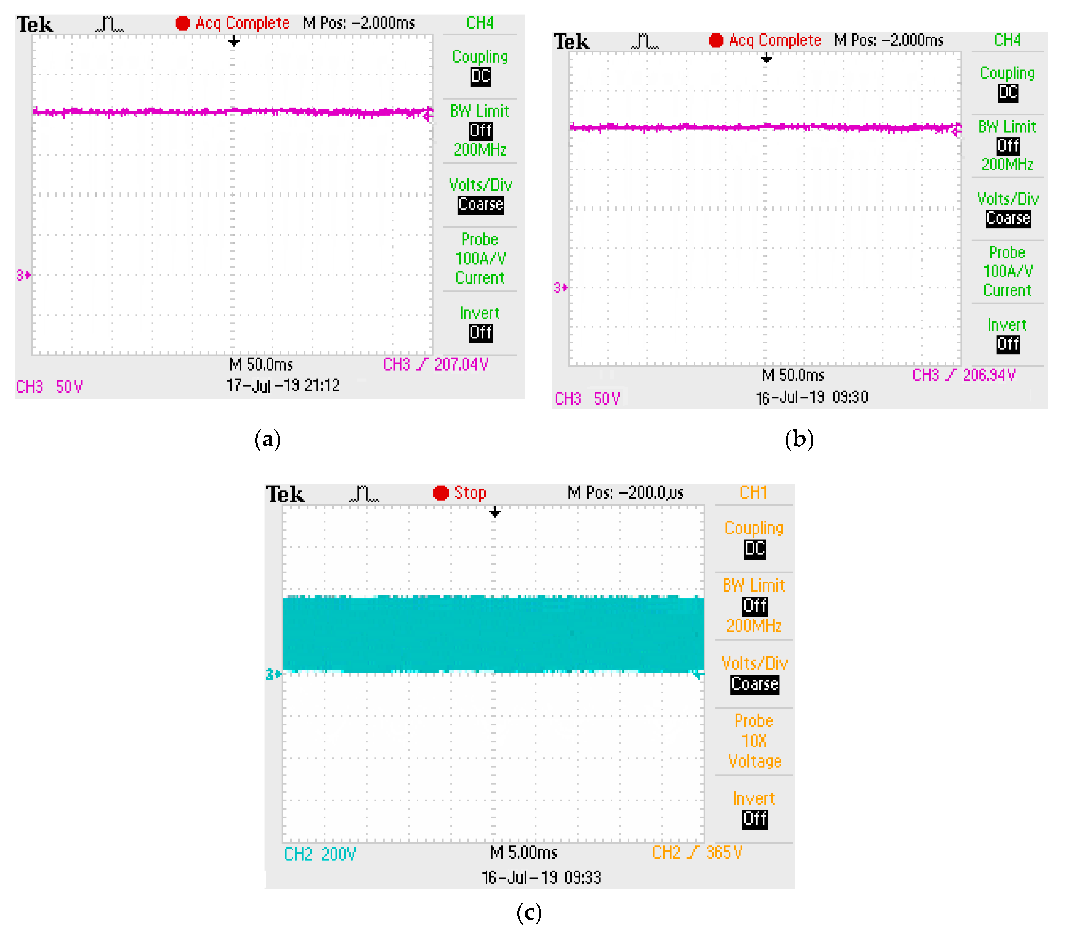
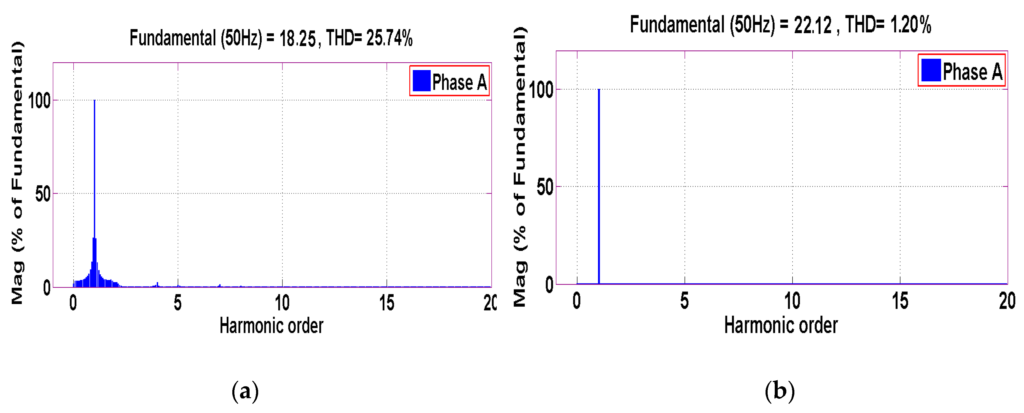
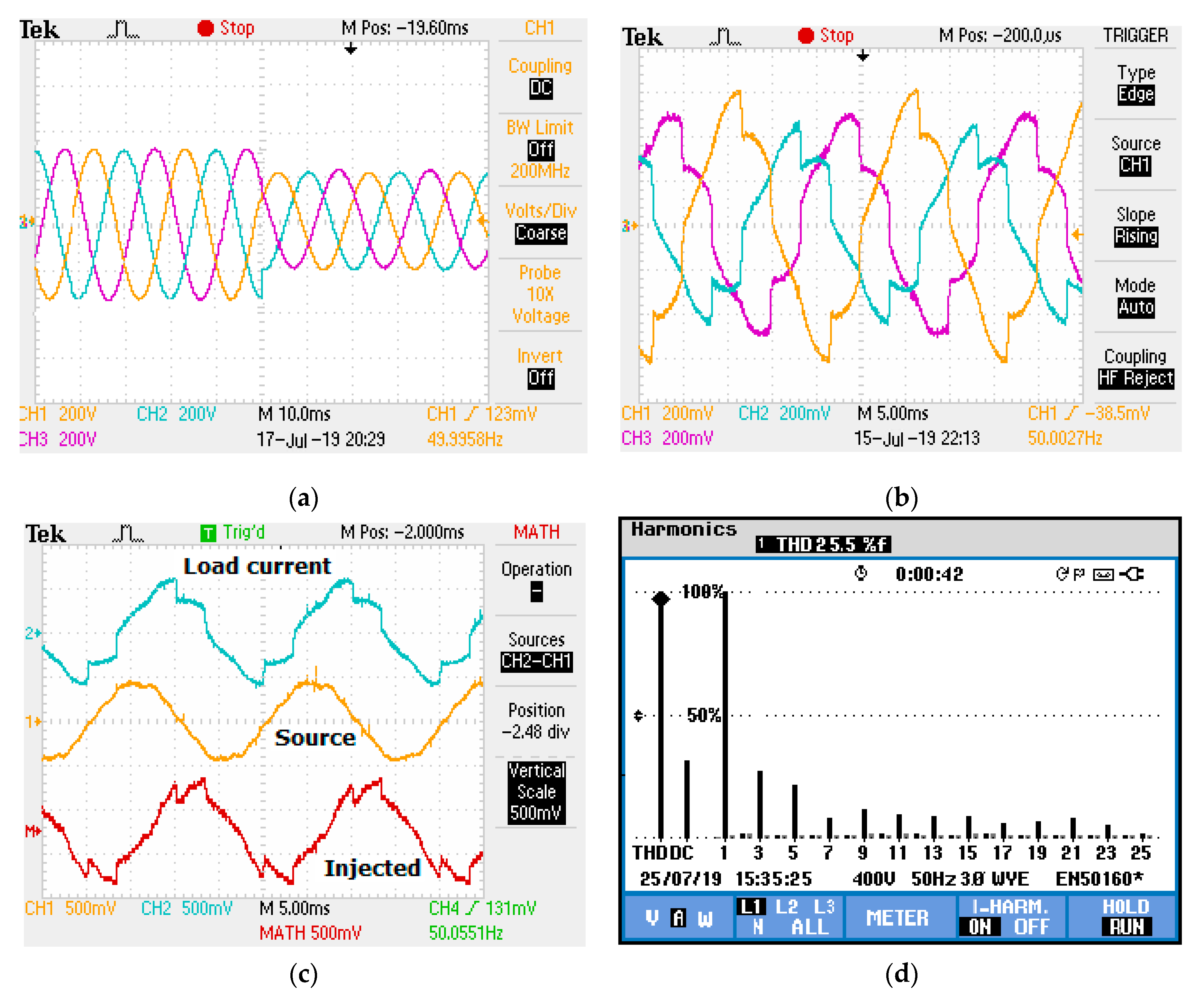
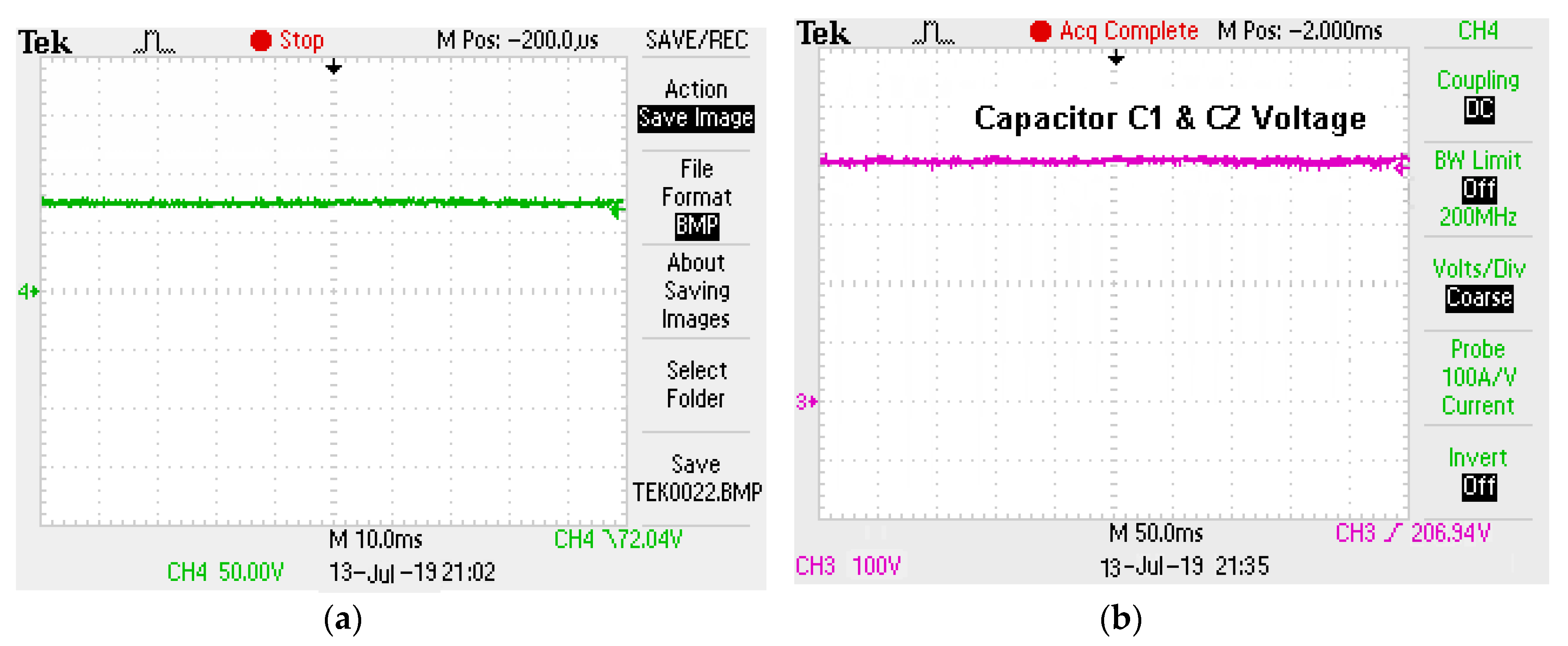
4. Simulation and Experimental Validation
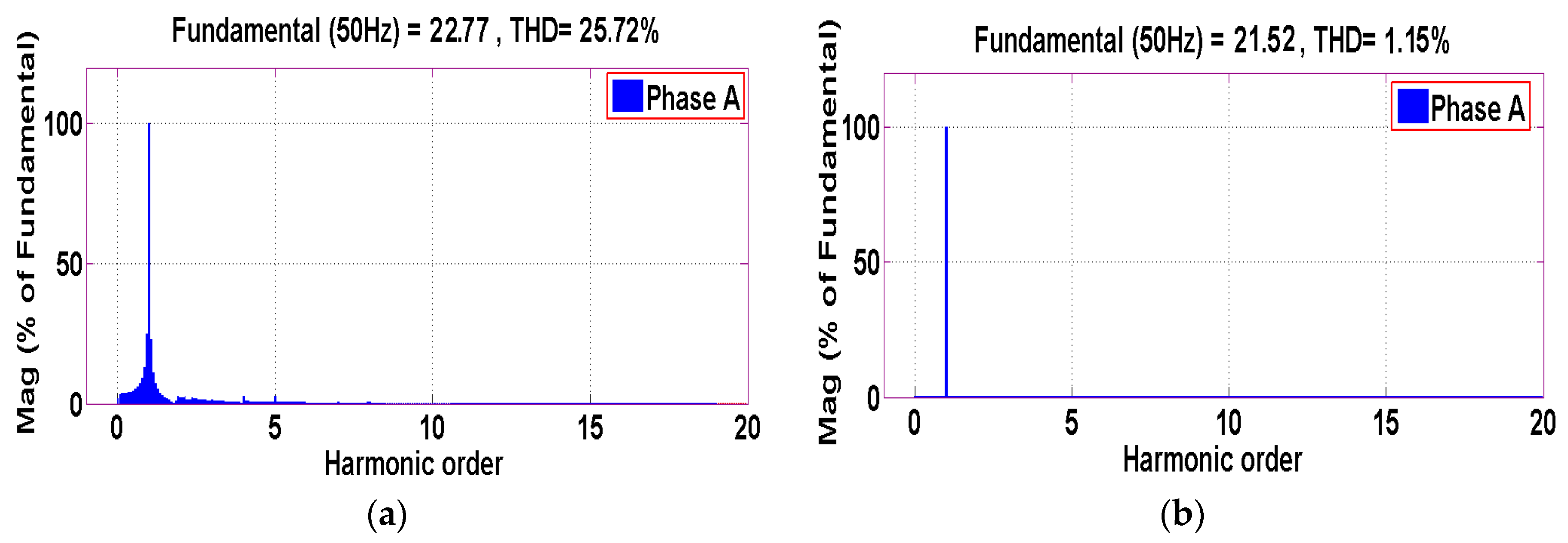
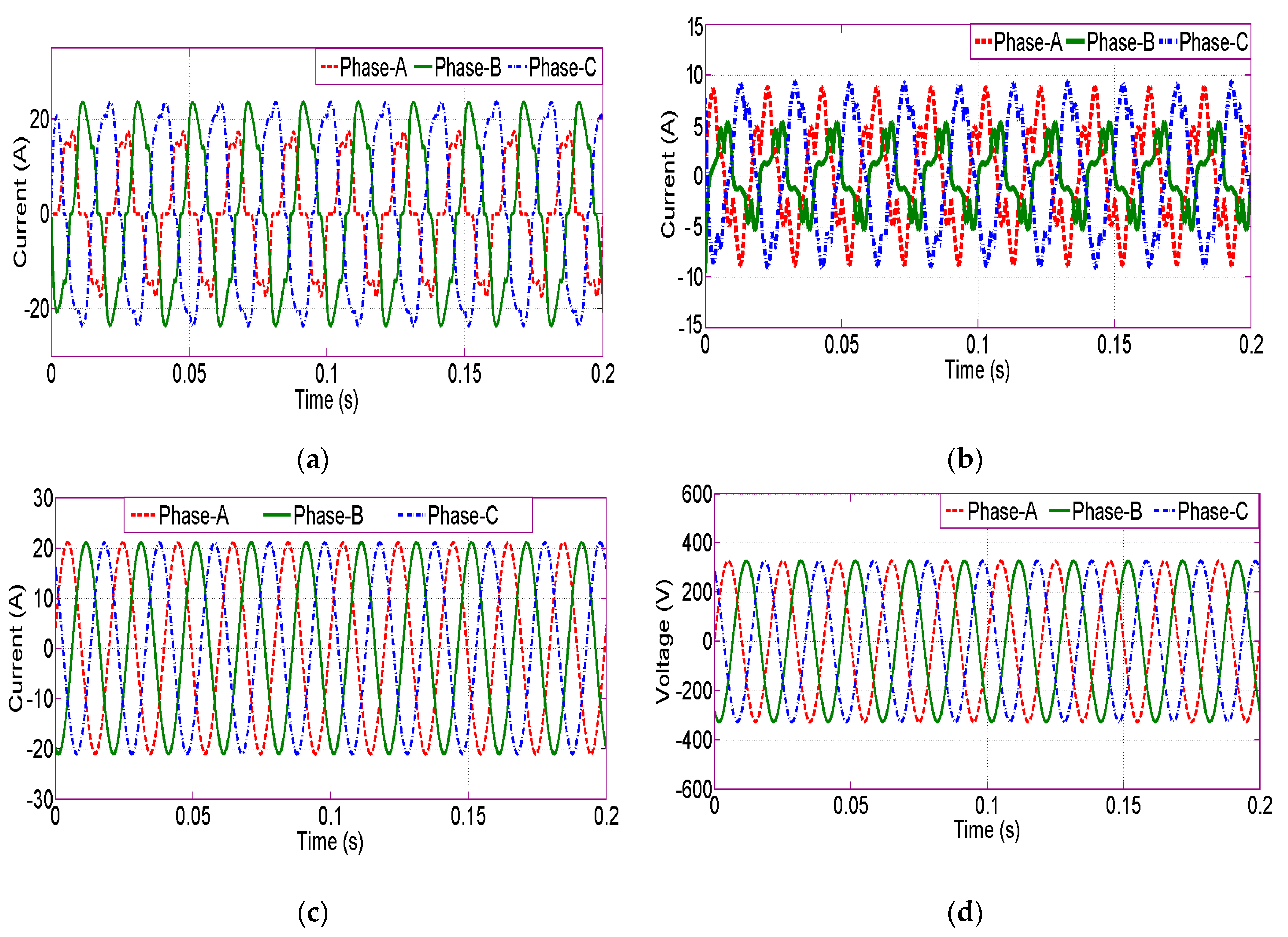
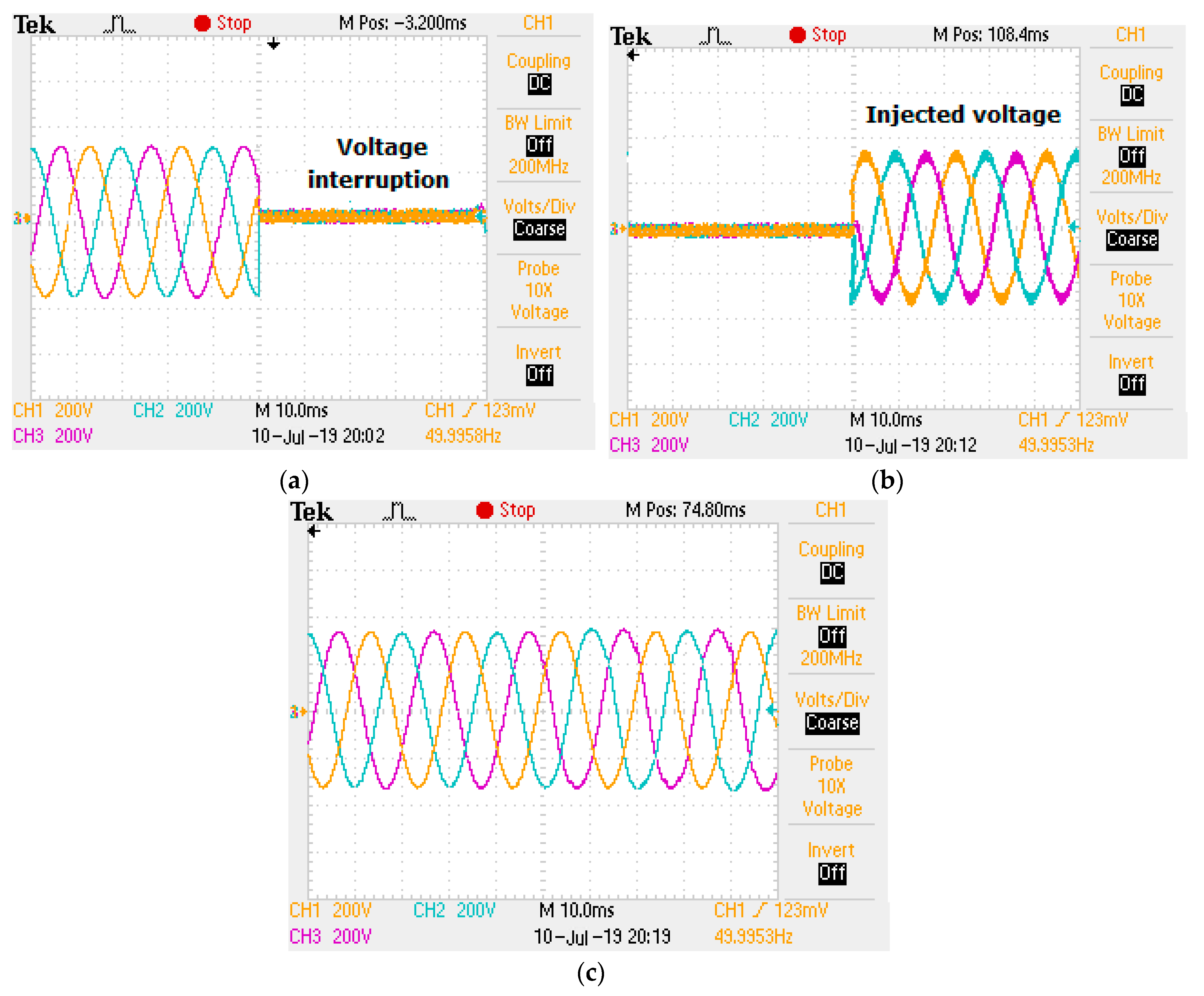
4.1. Balanced Supply Voltages and Load Currents
4.2. Balanced Voltages with Unbalanced Loads
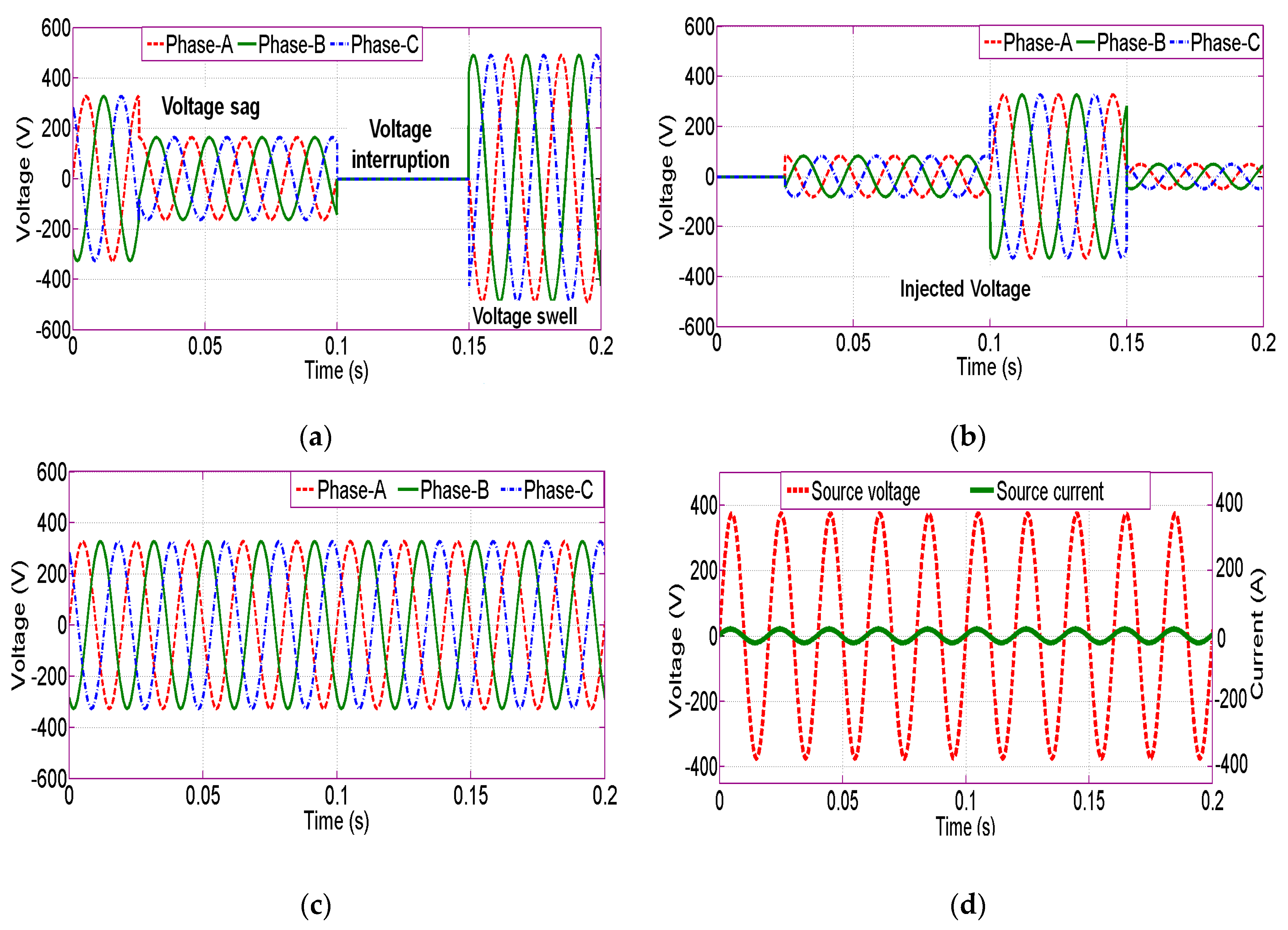
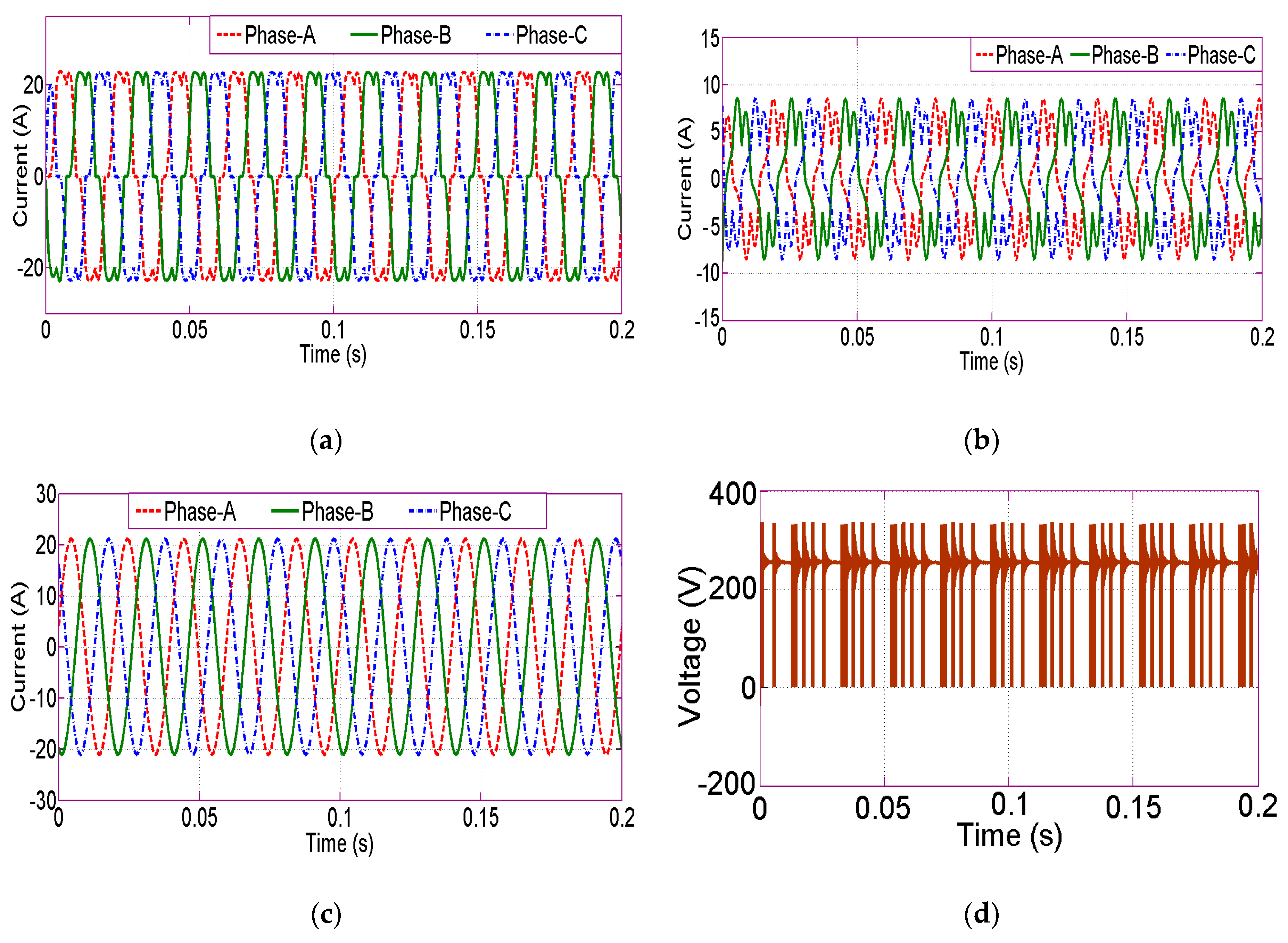
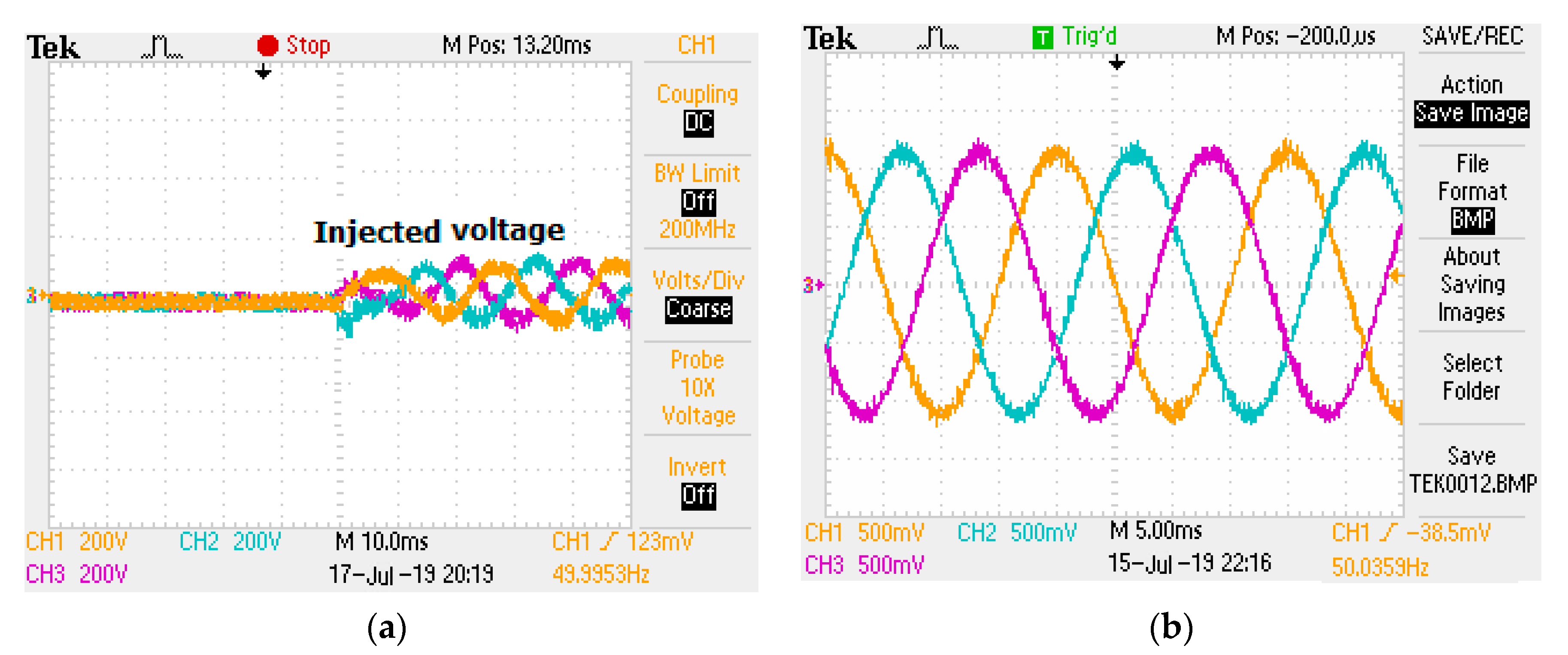
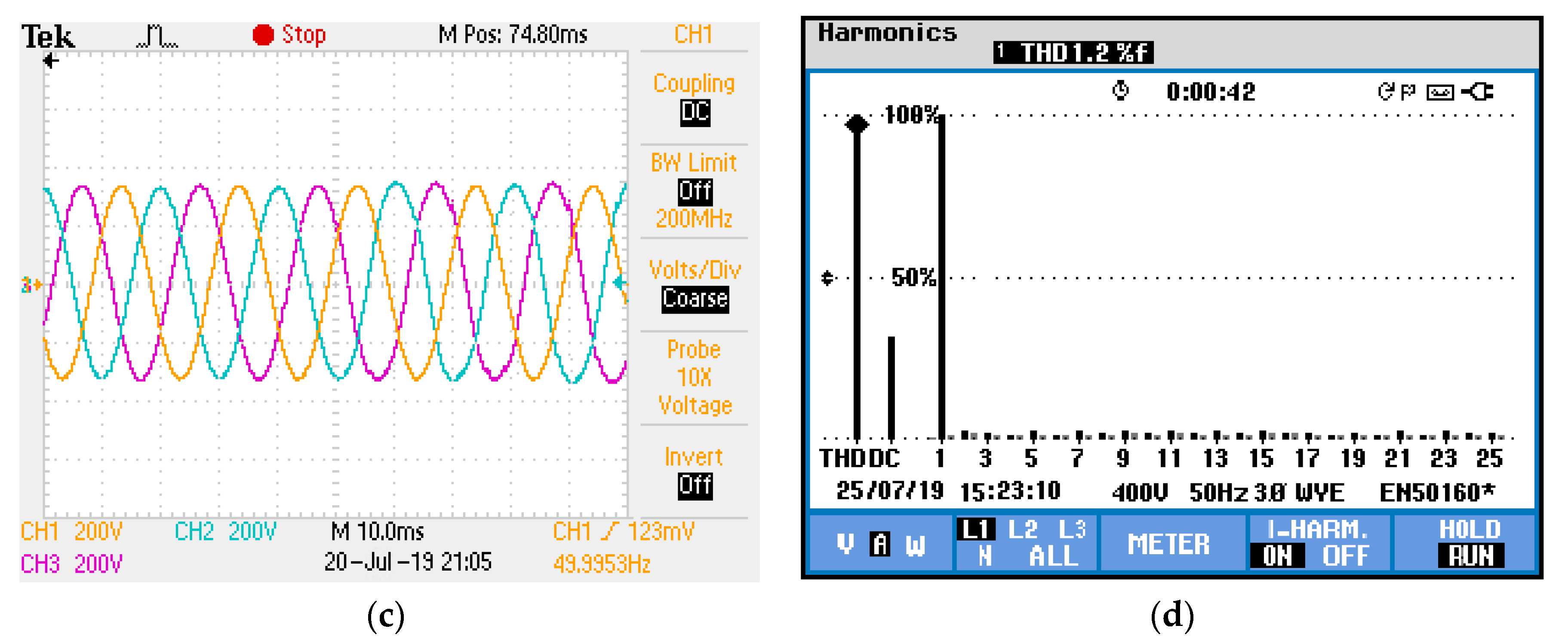
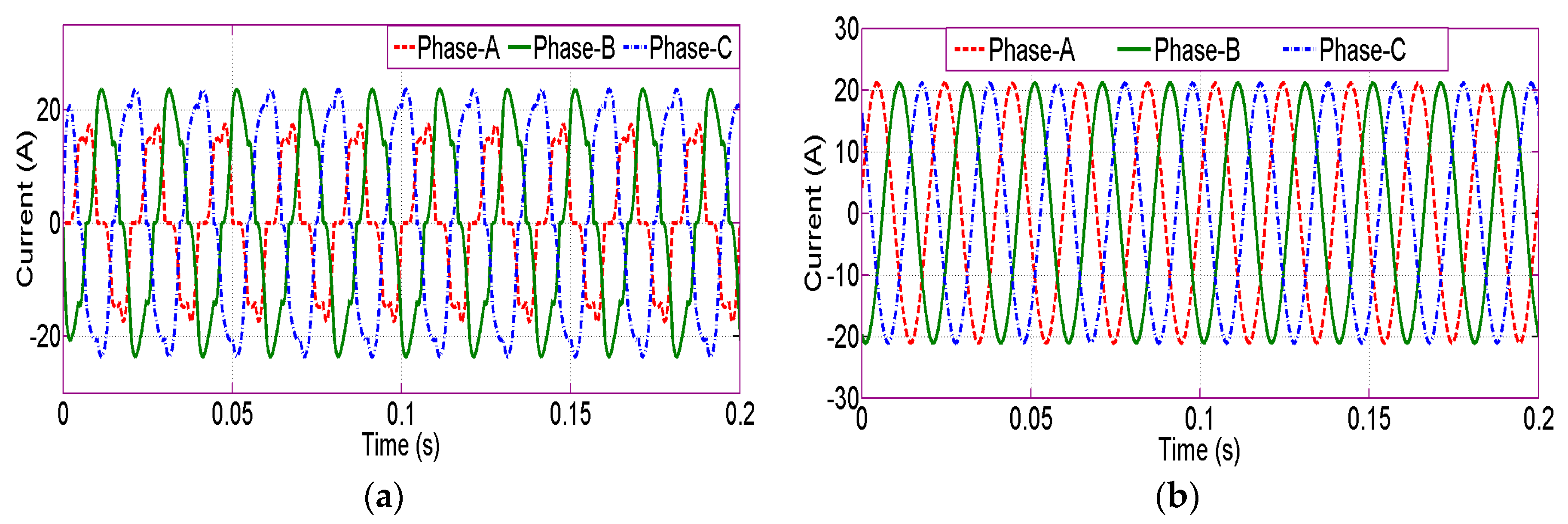
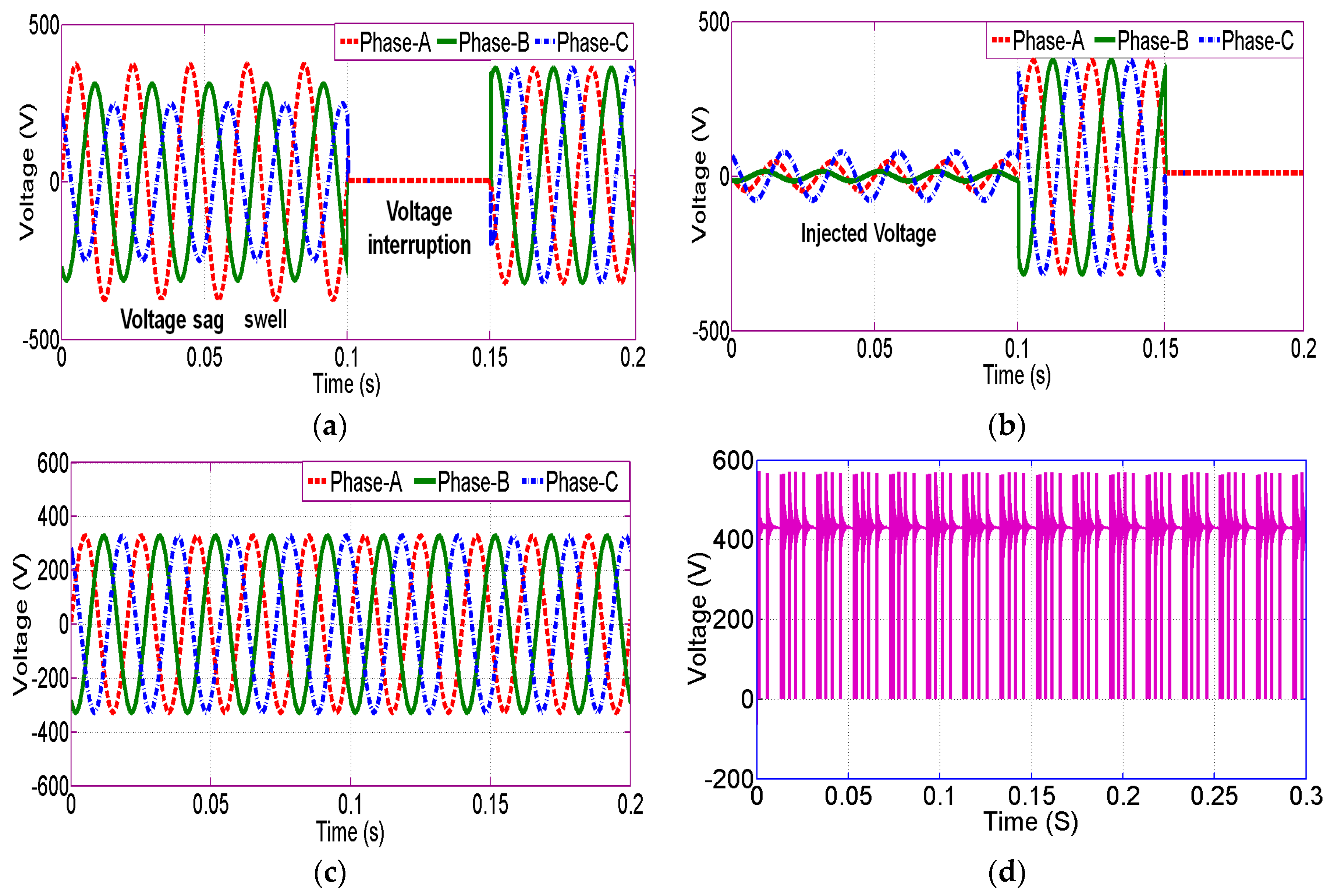
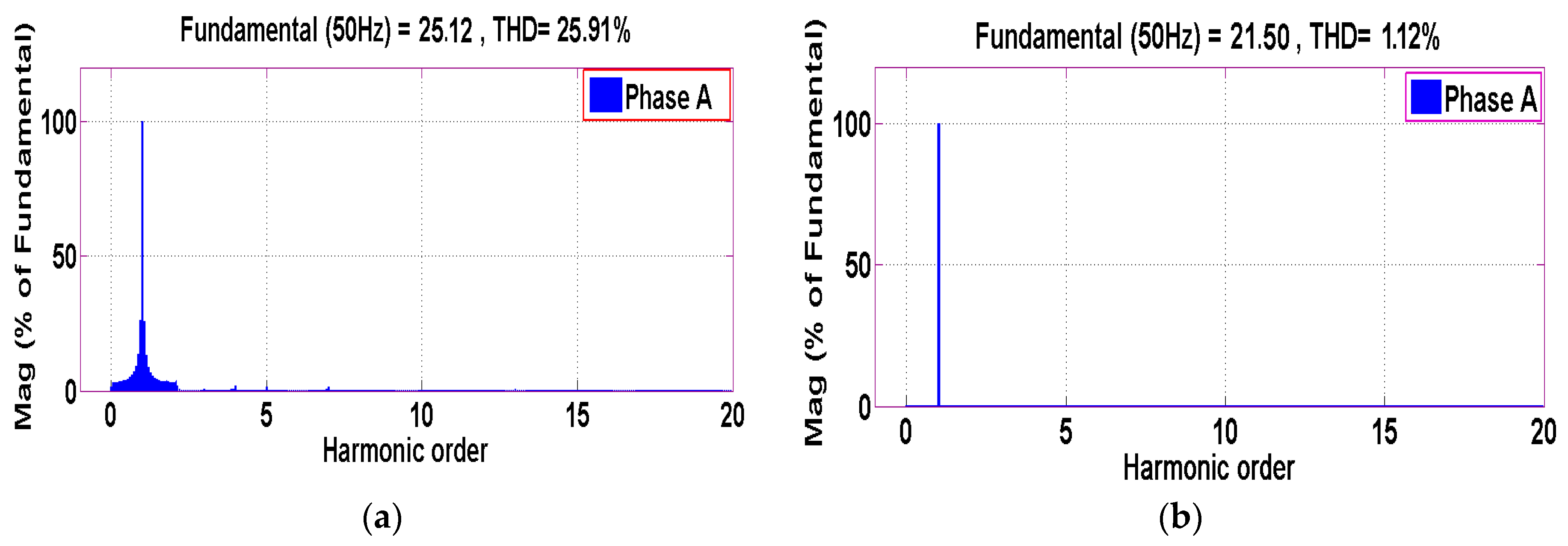
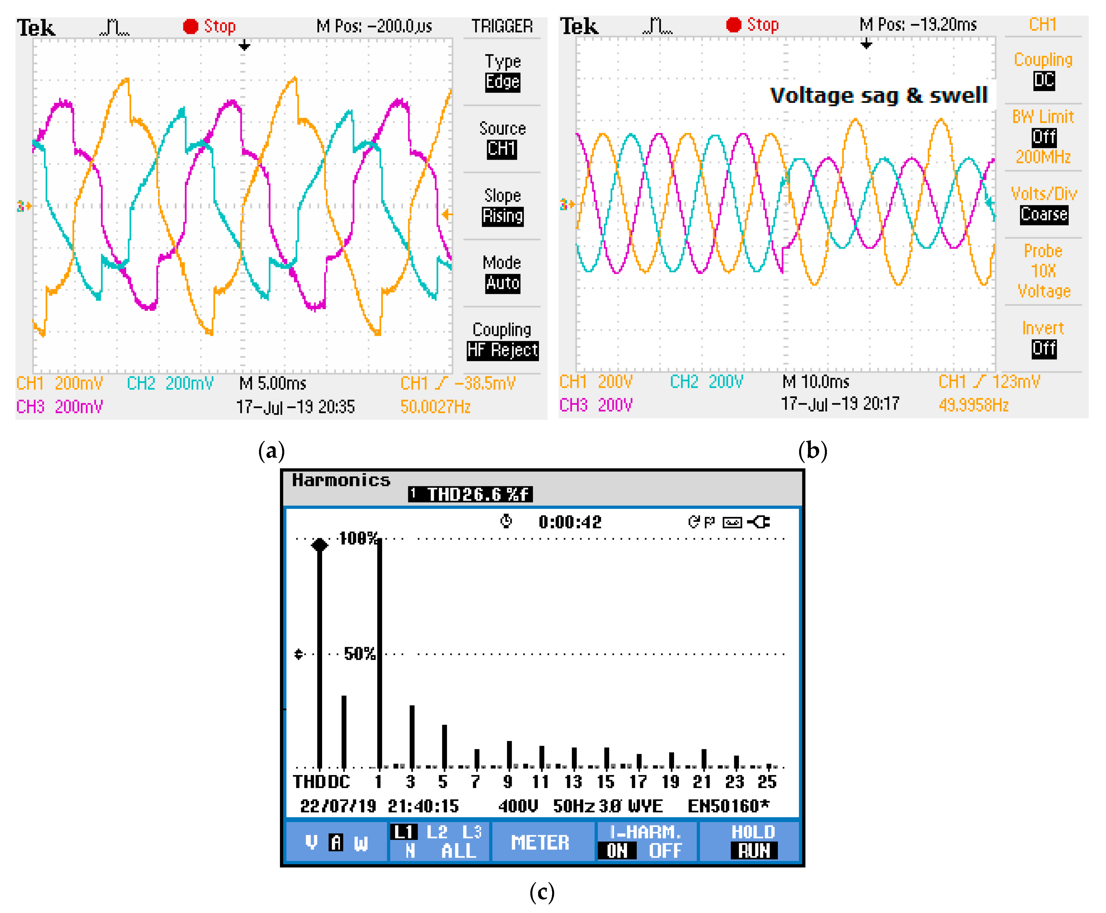
4.3. Unbalanced Voltages with Unbalanced Loads
5. Conclusions
Author Contributions
Funding
Conflicts of Interest
References
- Yao, Y.; Kang, L. The Virtual Harmonic Power Droop Strategy to Mitigate the Output Harmonic Voltage of the Inverter. Energies 2018, 11, 2196. [Google Scholar] [CrossRef] [Green Version]
- Ge, X.; Gao, F.; He, G.; Li, G. A unified power quality conditioner for the fault ride-through operation of photovoltaic power station. In Proceedings of the 2014 International Electronics and Application Conference and Exposition (PEAC), Shanghai, China, 5–8 November 2014; pp. 566–571. [Google Scholar]
- Jayanti, N.; Basu, M.; Conlon, M.F.; Gaughan, K. Optimising the rating of the UPQC for applying to the fault ride through enhancement of wind generation. In Proceedings of the 41st International Universities Power Engineering Conference, Newcastle-Upon-Tyne, UK, 6–8 September 2006; Volume 1, pp. 123–127. [Google Scholar]
- Hoon, Y.; Mohd Radzi, M.A.; Hassan, M.K.; Mailah, N.F. A Dual-Function Instantaneous Power Theory for Operation of Three-Level Neutral-Point-Clamped Inverter-Based Shunt Active Power Filter. Energies 2018, 11, 1592. [Google Scholar] [CrossRef] [Green Version]
- Sang, Y.; Yang, B.; Shu, H.; Na, A.; Zeng, F.; Yu, T. Fault Ride-Through Capability Enhancement of Type-4 WECS in offshore Wind Farm via Nonlinear Adaptive Control of VSC-HVDC. Processes 2019, 7, 540. [Google Scholar] [CrossRef] [Green Version]
- Khadkikar, V. Enhancing electric power quality using UPQC: A comprehensive overview. IEEE Trans. Electron. 2012, 27, 2284–2297. [Google Scholar] [CrossRef]
- Monteiro, L.F.; Aredes, M.; Couto, C.; Afonso, J.L. Control algorithms for a unified power quality conditioner based on three-level converters. Int. Trans. Electr. Energy Syst. 2014, 25, 2394–2411. [Google Scholar] [CrossRef]
- Devassy, S.; Singh, B. Dynamic performance of solar PV integrated UPQC-P for critical loads. In Proceedings of the 2015 Annual IEEE India Conference (INDICON), New Delhi, India, 17–20 December 2015; pp. 1–6. [Google Scholar]
- Chen, J.; Duan, W.; Yang, X.; Zhang, L.; Shan, Y.; Yang, B.; Shu, H.; Na, A.; Yu, T. Overall Adaptive Controller Design of PMSG Under Whole Wind Speed Range: A Perturbation Compensation Based Approach. Processes 2019, 7, 732. [Google Scholar] [CrossRef] [Green Version]
- Reisi, A.R.; Moradi, M.H.; Showkati, H. Combined photovoltaic and unified power quality controller to improve power quality. Solar Energy 2013, 88, 154–162. [Google Scholar] [CrossRef]
- Vijayakumar, M.; Vijayan, S. Extended reference signal generation scheme for integration of unified power quality conditioner in grid-connected photovoltaic system. Electr. Power Compon. Syst. 2015, 43, 914–927. [Google Scholar]
- Shrivastava, A.; Nene, P. Power quality enhancement using UPQC connected with PV arrays. In Proceedings of the 2015 Fifth International Conference on Communication Systems and Network Technologies ( CSNT), Gwalior, India, 4–6 April 2015; pp. 1232–1237. [Google Scholar] [CrossRef]
- Patel, A.; Chaturvedi, P. Performance of SRF-UVTG based UPQCDG for integration of solar PV with non-linear loads. In Proceedings of the 2016 IEEE International Conference on Power Electronics, Drives and Energy Systems (PEDES), Melaka, Malaysia, 28–29 November 2016; pp. 1–5. [Google Scholar]
- Khadkikar, V.; Chandra, A. A new control philosophy for a unified power quality conditioner (upqc) to coordinate load-reactive power demand between shunt and series inverters. IEEE Trans. Power Deliv. 2008, 23, 2522–2534. [Google Scholar] [CrossRef]
- Hoon, Y.; Mohd Radzi, M.A.; Hassan, M.K.; Mailah, N.F. Control Algorithms of Shunt Active Power Filter for Harmonics Mitigation: A Review. Energies 2017, 10, 2038. [Google Scholar] [CrossRef] [Green Version]
- Hekss, Z.; Lachkar, I.; Abouloifa, A.; Echalih, S.; Aourir, M.; Giri, F. Nonlinear Control Strategy of Single Phase Half Bridge Shunt Active Power Filter Interfacing Renewable Energy Source and Grid. In Proceedings of the 2019 American Control Conference (ACC), Philadelphia, PA, USA, 10–12 July 2019; pp. 1972–1977. [Google Scholar]
- Devassy, S.; Singh, B. Implementation of Solar Photovoltaic System with Universal Active Filtering Capability. IEEE Trans. Ind. Appl. 2019, 55, 3926–3934. [Google Scholar] [CrossRef]
- Yang, B.; Liu, K.; Zhang, S.; Zhao, J. Design and Implementation of Novel Multi-Converter-Based Unified Power Quality Conditioner for Low-Voltage High-Current Distribution System. Energies 2018, 11, 3150. [Google Scholar] [CrossRef] [Green Version]
- Chen, X.; Fu, Q.; Infield, D.G. PV grid-connected power conditioning system with Z-source network. In Proceedings of the 2009 International Conference on Sustainable Power Generation and Supply, Nanjing, China, 6–7 April 2009; pp. 1–6. [Google Scholar] [CrossRef]
- Zhang, J. Unified control of Z-source grid-connected photovoltaic system with reactive power compensation and harmonics restraint: Design and application. IET Renew. Power Gener. 2018, 12, 422–429. [Google Scholar] [CrossRef]
- Senguttuvan, S.; Vijayakumar, M. Solar photovoltaic system interfaced shunt active power filter for enhancement of power quality in three-phase distribution system. J. Circuit Syst. Comp. 2018, 27, 1850166. [Google Scholar] [CrossRef]
- Järvelä, M.; Seppo Valkealahti, S. Ideal Operation of a Photovoltaic Power Plant Equipped with an Energy Storage System on Electricity Market. Appl. Sci. 2017, 7, 749. [Google Scholar] [CrossRef] [Green Version]
- Villalva, M.G.; Gazoli, J.R.; Ruppert Filho, E. Comprehensive approach to modeling and simulation of photovoltaic arrays. IEEE Trans. Power Electron. 2009, 24, 1198–1208. [Google Scholar] [CrossRef]
- Xiao, F.; Dong, L.; Li, L.; Liao, X. A Frequency-Fixed SOGI-Based PLL for Single-Phase Grid-Connected Converters. IEEE Trans. Power Electron. 2017, 32, 1713–1719. [Google Scholar] [CrossRef]
- Patil, P.K.; Patel, H.H. Modified SOGI based shunt active power filter to tackle various grid voltage abnormalities. Eng. Sci. Technol. Int. J. 2017, 20, 1466–1474. [Google Scholar] [CrossRef]
- Langella, R.; Testa, A.; Alii, E. IEEE Recommended Practice and Requirements for Harmonic Control in Electric Power Systems. IEEE Stand. 2014, 519, 1–29. [Google Scholar]


| Parameters | Value | |
|---|---|---|
| Three-phase (phase voltage) | 230 V | |
| Shunt APF | Lf, Rf | 26 mH, 1.5 Ω |
| DC-link Voltage | Vdc | 520 V |
| DC-link capacitors | Cdc | 2200 µF |
| Filter (series APF) | Lse, Cse, Rsw | 5 mH, 80 µF, 1.5 Ω |
| Switching frequency | fs | 10 kHz |
| DC-DC converter | ||
| Inductor | L | 1 µH |
| Capacitance | C | 200 µF |
| Switching frequency | fsd | 20 kHz |
| No. of SPV cells | 6 × 10 | |
| Nominal SPV voltage | 12 V | |
| Maximum power | Pmp | 230 W |
| Voltage at Pmp | Vmp | 35.5 V |
| Current at Pmp | Imp | 6.77 A |
| Open Circuit Voltage | Voc | 43.6 V |
| Short Circuit Current | Isc | 7.37 A |
| Phase | Simulation Results | Experimental Results | ||||||||||
|---|---|---|---|---|---|---|---|---|---|---|---|---|
| Case: 1 | Case: 2 | Case: 3 | Case: 1 | Case: 2 | Case: 3 | |||||||
| Without PV-UPQC | With PV-UPQC | Without PV-UPQC | With PV-UPQC | Without PV-UPQC | With PV-UPQC | Without PV-UPQC | With PV-UPQC | Without PV-UPQC | With PV-UPQC | Without PV-UPQC | Without PV-UPQC | |
| Current THD (%) | Current THD (%) | Current THD (%) | Current THD (%) | Current THD (%) | Current THD (%) | Current THD (%) | Current THD (%) | Current THD (%) | Current THD (%) | Current THD (%) | Current THD (%) | |
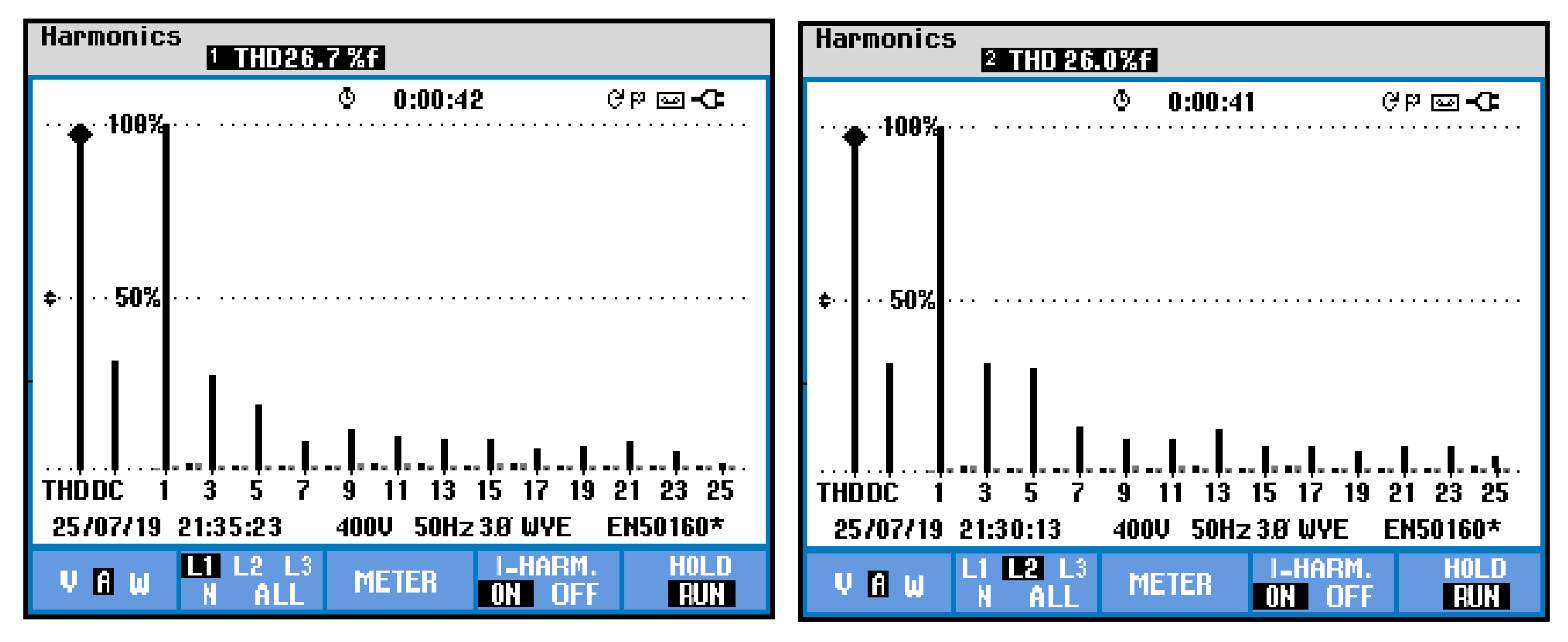
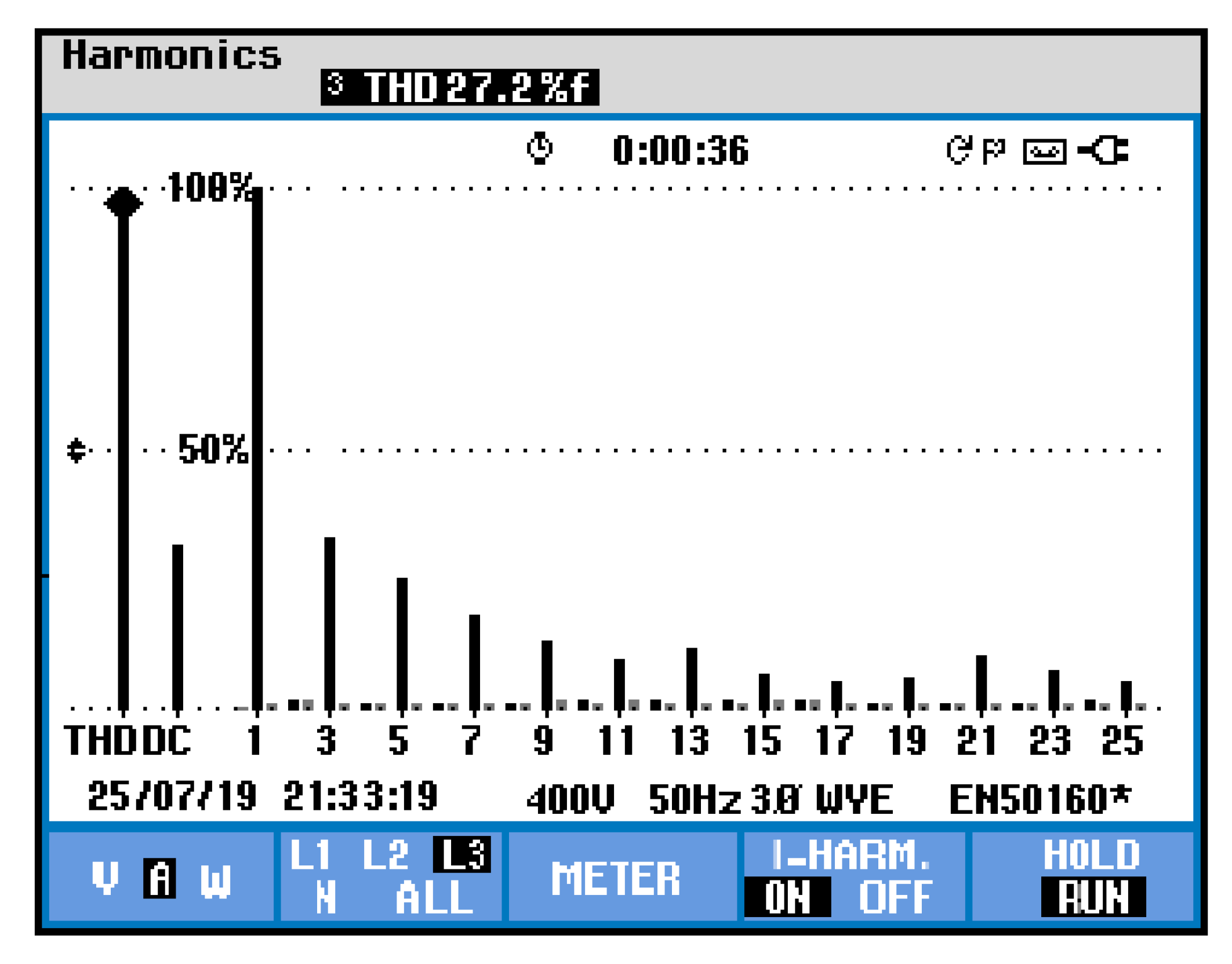
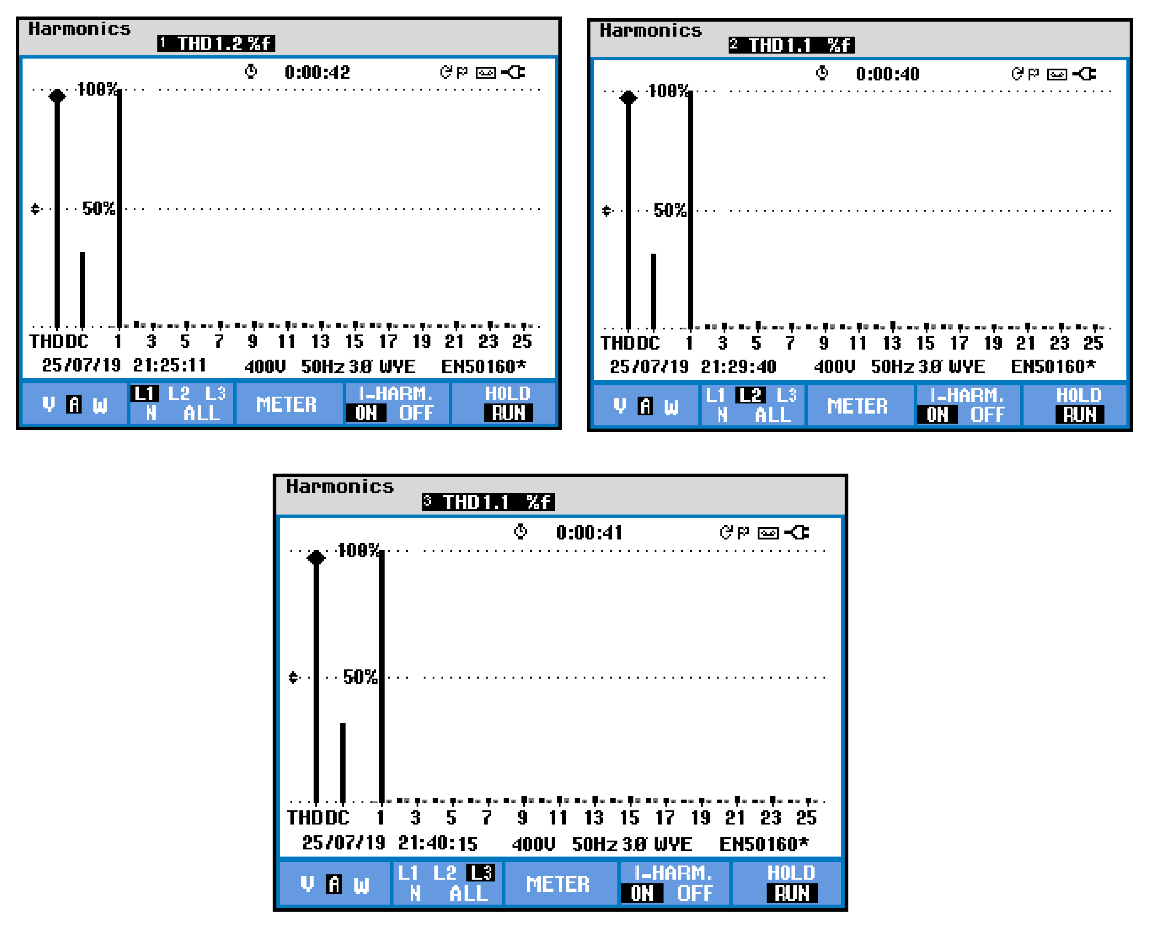
| A | 25.72 | 1.15 | 25.74 | 1.20 | 25.91 | 1.12 | 26.7 | 1.2 | 25.5 | 1.2 | 26.6 | 1.2 |
| B | 25.57 | 1.21 | 25.65 | 1.25 | 25.75 | 1.20 | 26.6 | 1.1 | 24.7 | 1.3 | 25.6 | 1.2 |
| C | 26.02 | 1.16 | 26.21 | 1.21 | 26.13 | 1.23 | 27.2 | 1.1 | 26.2 | 1.1 | 26.3 | 1.3 |
© 2020 by the authors. Licensee MDPI, Basel, Switzerland. This article is an open access article distributed under the terms and conditions of the Creative Commons Attribution (CC BY) license (http://creativecommons.org/licenses/by/4.0/).
Share and Cite
Muthuvel, K.; Vijayakumar, M. Solar PV Sustained Quasi Z-Source Network-Based Unified Power Quality Conditioner for Enhancement of Power Quality. Energies 2020, 13, 2657. https://doi.org/10.3390/en13102657
Muthuvel K, Vijayakumar M. Solar PV Sustained Quasi Z-Source Network-Based Unified Power Quality Conditioner for Enhancement of Power Quality. Energies. 2020; 13(10):2657. https://doi.org/10.3390/en13102657
Chicago/Turabian StyleMuthuvel, K., and M. Vijayakumar. 2020. "Solar PV Sustained Quasi Z-Source Network-Based Unified Power Quality Conditioner for Enhancement of Power Quality" Energies 13, no. 10: 2657. https://doi.org/10.3390/en13102657