1. Introduction
Heat recovery has been regarded as a major measure to increase energy efficiency in process systems engineering. It can also help to reduce the environmental burden by reducing waste heat emission. Heat exchanger network (HEN) retrofit is an effective way to utilise heat from process streams and to minimise the energy consumption [
1]. In the industrial application of HEN retrofit, different types of heat exchangers have their working temperature ranges and costs. The type of heat exchanger should be wisely selected for different usages and applications to ensure the heat exchangers can work under certain conditions with a relatively economic investment cost.
In the HEN retrofit problem, there are generally three approaches, i.e., Pinch Analysis (PA), mathematical programming, and a combined method [
2]. The first work of PA was developed by Linnhoff and Flower [
3]. Following their innovation, many PA-based graphical methods were proposed for HEN retrofits such as the Retrofit Thermodynamic Diagram (RTD) [
4], Stream Temperature vs. Enthalpy Plot (STEP) [
5], Temperature Driving Force (TDF) [
6], and Energy Transfer Diagram (ETD) [
7], which are widely used in the retrofit applications. Some extended methods and applications based on the above studies were reported. Lai et al. [
8] proposed a combined STEP and heat exchanger area versus enthalpy (A vs. H) plot to customise a retrofit design toward a desired investment payback period. Kamel et al. [
9] applied TDF on an existing HEN in an Egyptian refinery to improve energy saving with minor structural modifications. Lal et al. [
10] modified the ETD and proposed a heat surplus-deficit table for the HEN retrofit to achieve energy saving.
RTD has been a particularly useful graphical visual tool. It can display the driving force around the heat exchanger and heat capacity flow rate graphically. Yong et al. [
11] modified the RTD and proposed a Shifted Retrofit Thermodynamic Diagram (SRTD). In SRTD, the hot streams are shifted by subtracting the minimum allowed temperature difference (ΔT
min), and then the feasibility of implementing a heat exchanger can be visually seen by connecting both lower and higher temperature sides of hot and cold streams. If the slope of the connecting lines is negative, then it illustrates that the heat exchanger implementing plan violates the Pinch Rule. SRTD was later extended to the Shifted Retrofit Thermodynamic Grid Diagram (SRTGD) by Yong et al. [
12]. It uses a dashed line to indicate the location of the Process Pinch. By applying this diagram, pinches can be detected, and the retrofit plan can be determined easier.
Apart from these graphical methods for HEN retrofit, mathematical programming has also been used in the retrofit design. Pan et al. [
13] developed mixed-integer linear programming (MILP)-based iterative method for HEN retrofit. Their method fixed the logarithmic mean temperature difference (LMTD) in the original problem and executed two iteration loops to achieve certain energy-saving or net present value. Zhang and Rangaiah [
14] applied integrated differential evolution to solve the HEN retrofit problem in one step. Onishi et al. [
15] proposed a mathematical programming model for HEN retrofit, considering the pressure recovery of process streams to enhance heat integration. Pavão et al. [
16] proposed an extended superstructure model and a corresponding meta-heuristic solution approach for the HEN retrofit problem. Wang et al. [
17] developed a mathematical model based on the structure of the SRTGD and a two-stage method. In the first stage, the mathematical model was solved to obtain the topology of the HEN, with the aim of minimising utility and investment costs. While in the second stage, a particle swarm optimisation (PSO) algorithm was applied to adjust the inlet and outlet temperatures of each heat exchanger to achieve the goal of minimising the payback period based on the obtained topology from the first stage. This method considers the cost of utility and investment. It makes the retrofit design based on SRTGD more effective.
In the HEN retrofit process, achieving energy saving is one important task; another issue is to ensure the selected heat exchanger type can satisfy the heat transfer requirement between streams and has a relatively lower cost. Different types of heat exchangers such as shell and tube, double-pipe, compact plate, and spiral tube have their working temperature ranges and capital costs. These issues should be considered in the retrofit design process to determine an economic plan. Soršak and Kravanja [
18] proposed a mixed-integer nonlinear programming (MINLP) model for HEN synthesis and modelled the selection of heat exchanger types. Fieg et al. [
19] developed a hybrid genetic algorithm for HEN design. The investment and utility costs were calculated separately in a user subroutine to consider the specificity of heat exchangers. Sun et al. [
20] presented the Stream Temperature vs. Enthalpy Plot Supertargeting (STEPS) method to optimise the cost of HEN. In their proposed step-by-step method, the heat exchanger types are considered and the capital cost is calculated. These previous papers considered the selection of heat exchanger types for the synthesis problem, the HEN retrofit with the consideration of heat exchanger types requires study. A method should be developed to consider both insights of thermodynamic and suitable heat exchanger type selection for HEN retrofit for potential industrial implementation.
The capital cost is the main criterion used to determine the selected heat exchanger type. Rathjens and Fieg [
21] proposed a MINLP model and a genetic algorithm coupled with a deterministic local optimisation approach for HEN synthesis. In their model, the cost functions for each connection of heat source and sink are considered to make solutions more efficient. Aguitoni et al. [
22] proposed a combined simulated annealing and differential evolution algorithm to minimise the sum of heat exchanger investment and energy cost. Kang and Liu [
23] proposed three strategies to minimise the investment cost for the multi-period HEN retrofit. Ayotte-Sauvé et al. [
24] proposed a stepwise approach for HEN retrofit to minimise the investment costs for new and retrofit heat exchangers as well as utility costs. Nemet et al. [
25] proposed an MINLP model for the optimal design of HEN, considering the lifetime cost.
There are several advantages of using SRTGD as a visualisation tool in the HEN retrofit applications. It can identify the Process Pinch through the diagram. It is easy to check whether the retrofit plan violates the Pinch Rule [
26], and to find if there is still potential for more heat recovery. It also shows the temperature range of each heat exchanger for hot and cold streams, which is a benefit that can be used in the heat exchanger type selection. However, there is still a need to develop a tool that can be used to help designers to select suitable types of heat exchangers visually. This tool should be easy to master and can show insights into network design.
To solve the above-mentioned issue, an SRTGD with the shifted temperature ranges of heat exchangers (SRTGD-STR) is developed as an effective tool for determining the retrofit plan of HENs and selecting feasible and cost-minimised heat exchanger types. The structure of the paper is organised as follows:
Section 2 presents the detailed method of utilising this proposed visualisation tool to increase heat recovery and debottleneck an existing process. An illustrative example of how to implement this method is studied.
Section 3 demonstrates a case study of the SRTGD-STR to show its effectiveness, and
Section 4 presents the conclusion.
2. Methodology
There are several different variants of heat exchangers, with the common types employed in the industry [
27] including:
Shell and tube heat exchangers;
Double-pipe heat exchangers;
Compact plate heat exchangers;
Spiral plate heat exchangers;
Spiral tube heat exchangers;
Scraped-wall heat exchangers.
Illustrations of these heat exchangers and a detailed list of heat exchanger types can be found in Ref. [
27].
This paper develops SRTGD-STR. This diagram considers these previously mentioned heat exchanger types in the retrofit design process. The detailed method of implementing the SRTGD-STR is introduced in this section using Example 1 data (
Table 1).
The notation of the heat transfer used in this work for all topology diagrams is the following:
H(number): Utility heater;
C(number): Utility cooler;
E(number): Recovery heat exchanger.
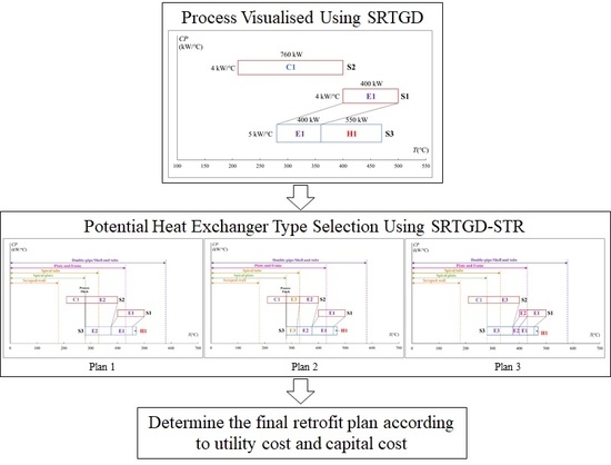
2.1. Process Visualised Using SRTGD
The first step is to identify the hot and cold process streams that have the potential for heat exchange. The flow rates, supply and target temperatures, and heat capacities of streams should be used to determine the utility targets. The stream conditions such as medium, pressure, viscosity, individual heat transfer coefficient, and material corrosiveness should also be extracted.
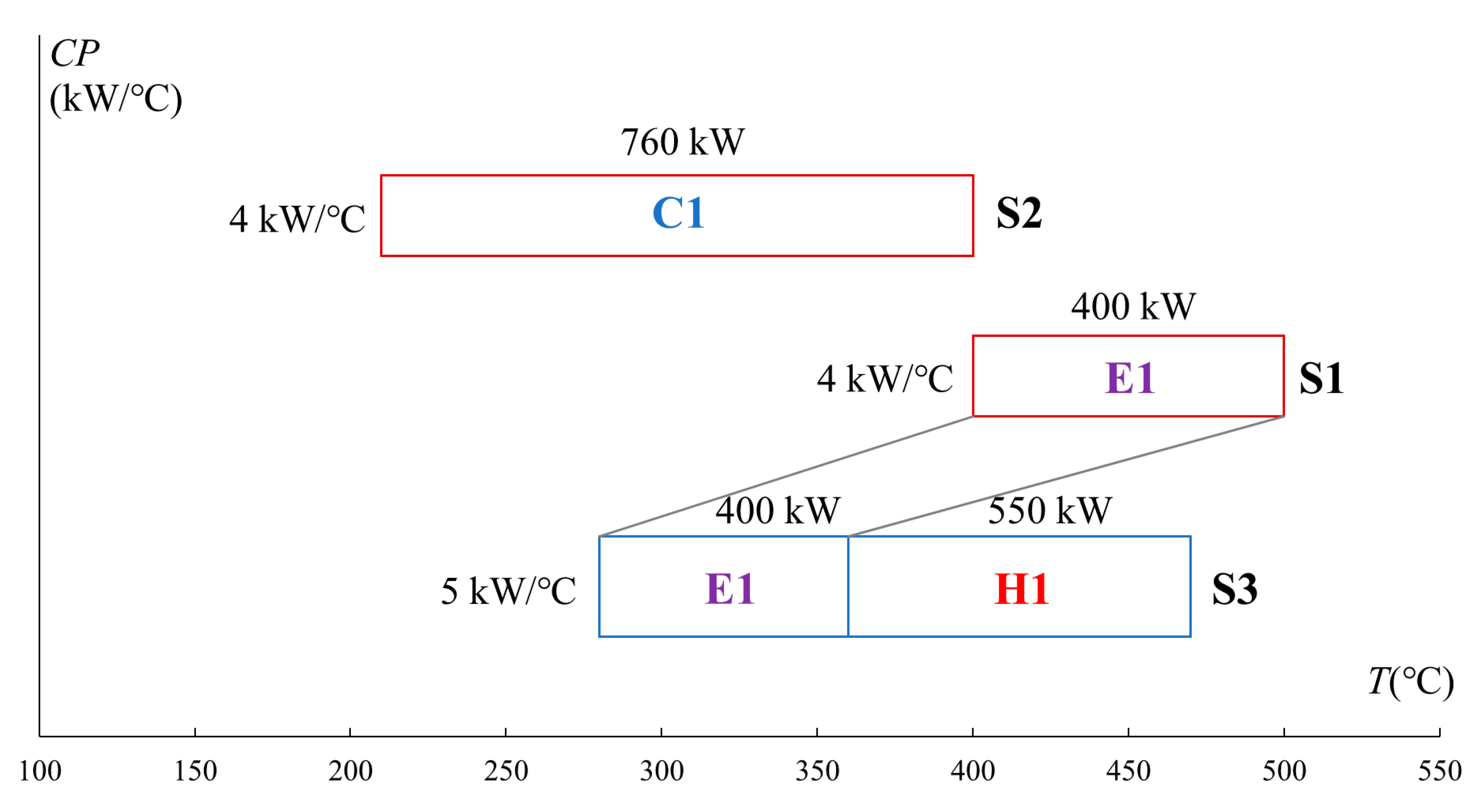
Table 1 is an example to show the data extracted from a process. There are three streams, and an existing heat exchanger is connecting stream 1 and 3 for heat recovery. In this example, ΔT
min is set at 20 °C.
The developed SRTGD-STR is the extension of SRTGD proposed by Yong et al. [
12]. SRTGD is used to identify the potential retrofit plan regarding heat recovery. The streams extracted are presented on the SRTGD according to their temperature ranges and heat capacity flow rates (CPs). For better visualisation, the cold streams are usually presented on the downside of the graph and hot streams are on the upside of the graph. If the slope of the link between heat exchangers is negative, this indicates an infeasible implementation of heat exchangers. Stream names are shown on the right side of each stream. The heat capacity flow rate of each stream can be observed on the y-axis. Supply and target temperatures of streams and heat exchangers can be observed on the x-axis. Pinch points are identified when the link between one cold and one hot stream is vertical.
SRTGD is capable of providing visual information in choosing heat paths. The temperatures of hot streams are shifted in the SRTGD. It can also help the designers to find the Network Pinch and identify the retrofit plan for maximum heat recovery. The detailed method for drawing an SRTGD and using SRTGD for HEN retrofit can be found in Ref. [
12].
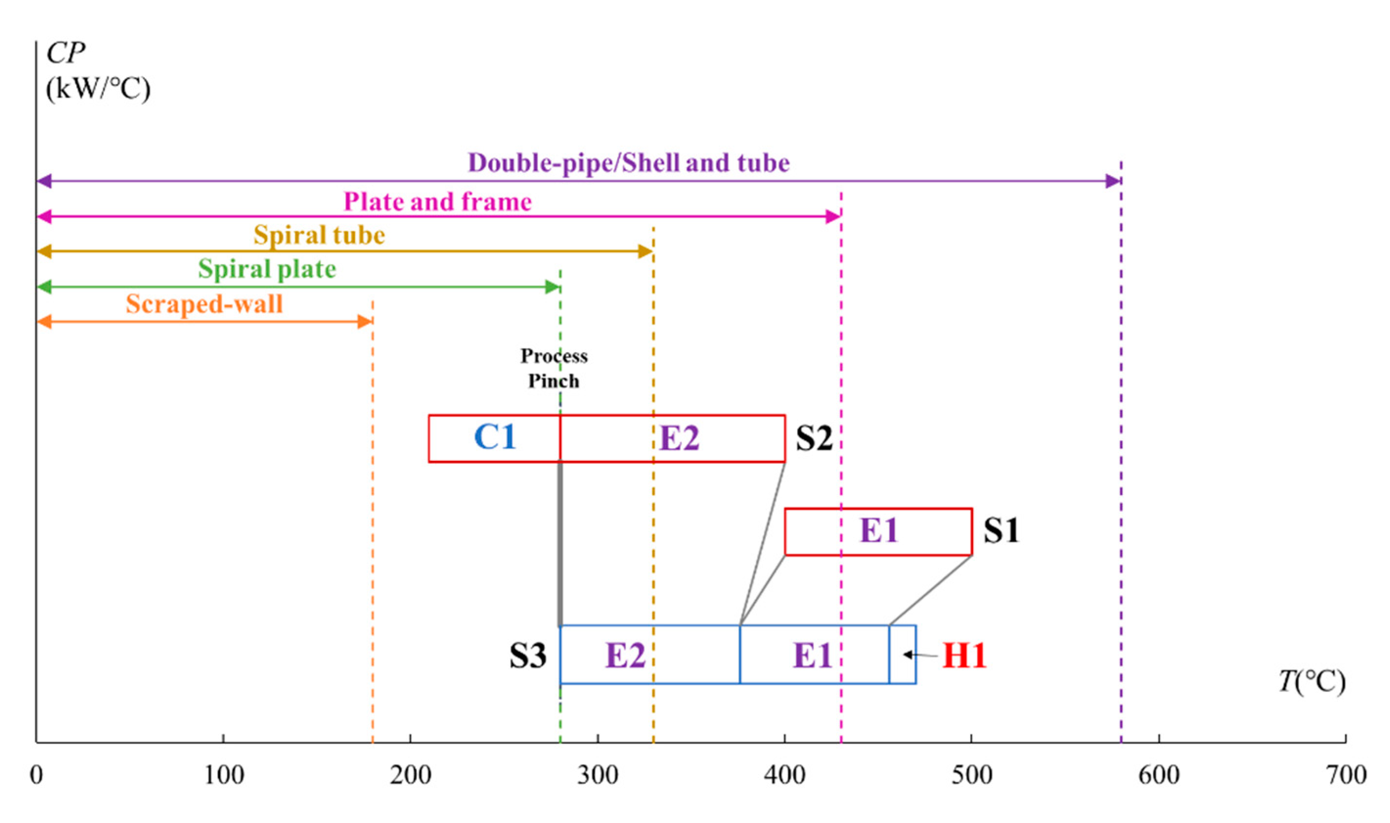
Figure 1 shows the SRTGD of illustrative Example 1.
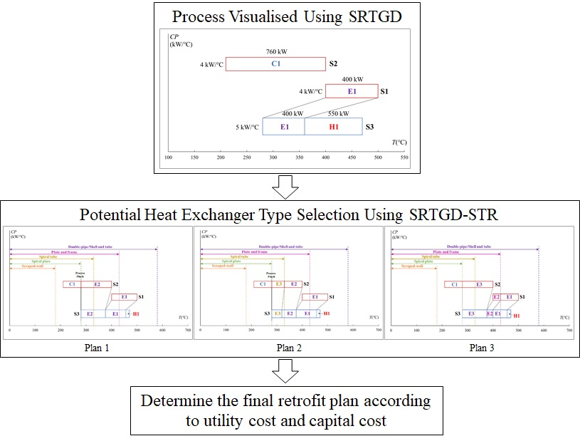
2.2. Potential Heat Exchanger Type Selection Using SRTGD-STR
When the heat paths are identified by SRTGD, the next step is to select the feasible and economical heat exchangers used for heat recovery. In the proposed SRTGD-STR, the allowable temperature ranges of different heat exchanger types are coupled in the diagram. The area of hot and cold streams connected by one heat exchanger should be in its temperature range. When determining a retrofit plan, this diagram can help easily identify the boundary of the heat exchangers.
The shifted temperature ranges of heat exchangers are added in the SRTGD-STR to help select the heat exchanger types according to the data given in
Table 2. As the temperatures of hot streams are shifted temperature in the SRTGD scale, the upper boundary of temperature ranges of heat exchangers in the diagram should also be shifted by minus ΔT
min of the studied case. The suitability of each heat exchanger type for transferring heat between streams depends on the specifications and requirements of the application.
Table 2 lists several commonly used heat exchanger types, their temperature ranges, and normal area ranges. In the retrofit design process, these factors should be considered together with the aim of utility saving.
If the temperature of some potential heat recovery range passes through the temperature range boundary of some types of heat exchangers or temperature ranges of some heat exchangers are in the range of more than one heat exchanger type, then focus should be given to this heat path. If the heat recovery range passes through the temperature range boundaries, then whether to implement more than two heat exchangers on one heat path should also be considered to achieve the minimum retrofit cost.
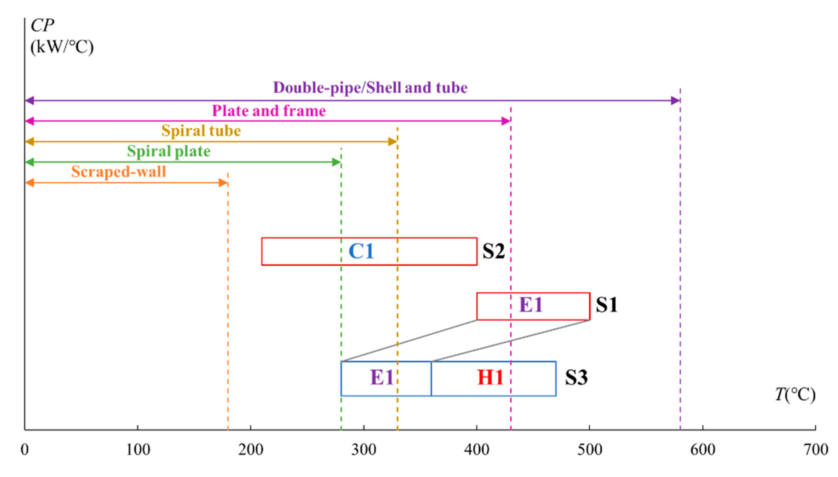
By implementing the data from
Table 2 to illustrative Example 1, the corresponding SRTGD-STR is shown in
Figure 2. The working temperature range of these heat exchanger types is shifted by minus ΔT
min, which is 20 °C in this example. As seen in
Figure 2, stream S2 is within the shifted temperature range of plate and frame, double-pipe, and shell-and-tube heat exchangers, which means these three types of heat exchangers can be applied without the consideration of supply and target temperatures. S2 also comes across the upper-temperature boundaries of the spiral tube and spiral plate heat exchangers. It indicates the possibility of using different types of heat exchangers on a single stream, and these two types of heat exchangers should be examined based on the Pinch Rules.
To fully utilise the heat from the hot stream, four retrofit plans are proposed based on SRTGD-STR. The first retrofit plan is shown in
Figure 3 and uses one new heat exchanger between streams 2 and 3.
As can be observed from
Figure 3, some parts of the shifted temperature range of the new heat exchanger are higher than 330 °C, which is higher than the upper bound of the spiral tube heat exchanger. Double-pipe, plate and frame, or shell and tube heat exchangers can be used. The method to determine which type of heat exchanger should be used is explained in
Section 2.3. In this plan, 480 kW of heat is exchanged between the streams S2 and S3. To not violate the Pinch Rule, stream 2 uses E2 and C1 to reach the target temperature. The vertical line indicates the Process Pinch.
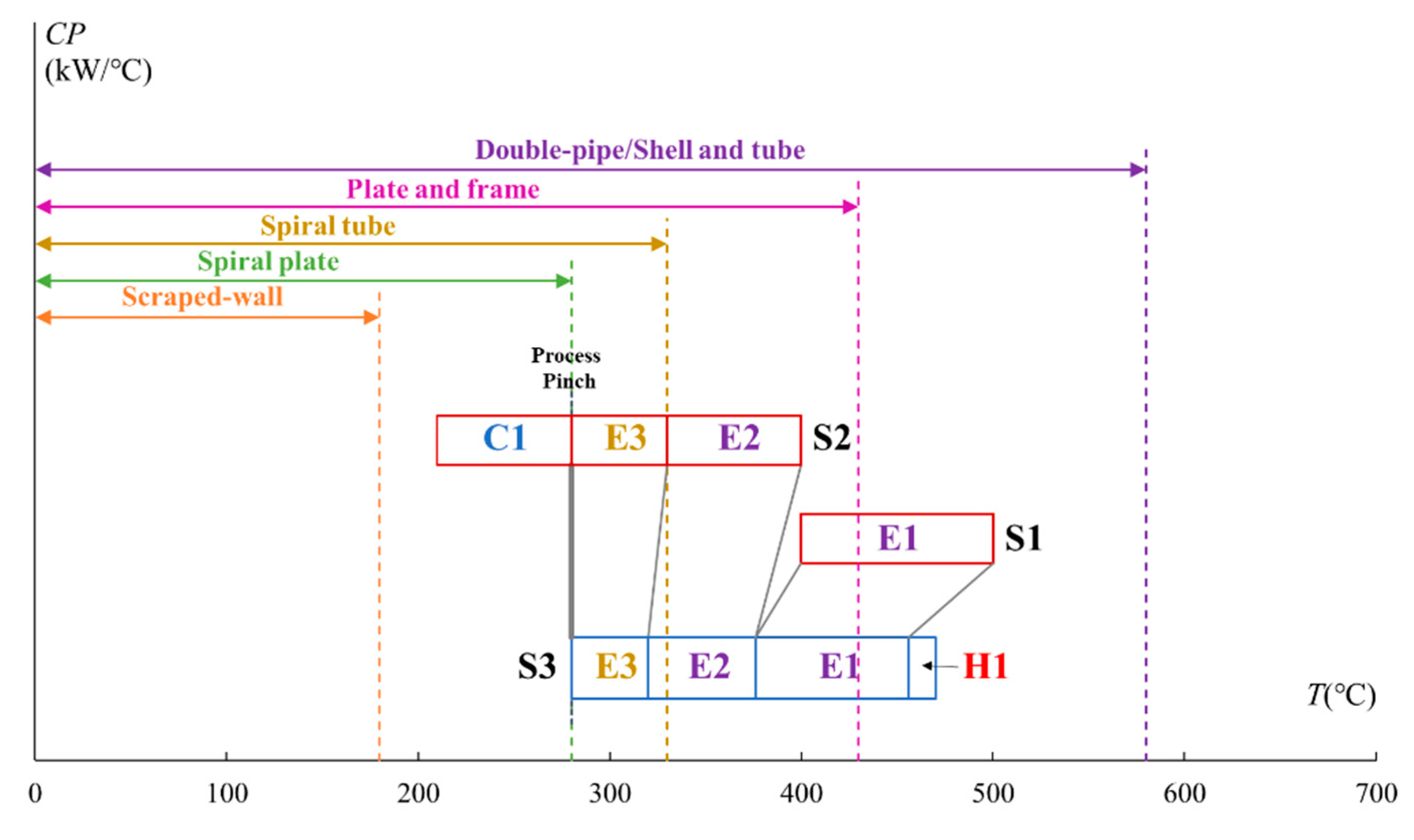
The second retrofit plan (
Figure 4) considers implementing a spiral tube heat exchanger for this HEN. It is easy to identify the retrofit plan based on the SRTGD-STR. To implement a spiral tube heat exchanger to this HEN, the highest shifted temperature on both hot and cold streams could not be higher than 330 °C, which is also marked on the diagram. For heat exchanger E3 (spiral tube), considering the hot stream S2 has a relatively lower heat capacity flow rate than the cold stream, the shifted inlet temperature in the hot stream should not be higher than the shifted upper bound of implementing a spiral tube heat exchanger. The inlet and outlet temperatures of heat exchanger E2 as well as E1 can also be determined.
Using a spiral plate for heat recovery is considered. However, the upper-temperature boundary of the spiral plate heat exchanger minus the ΔTmin equals the inlet temperature of stream S3. It is not feasible to use a spiral plate heat exchanger.
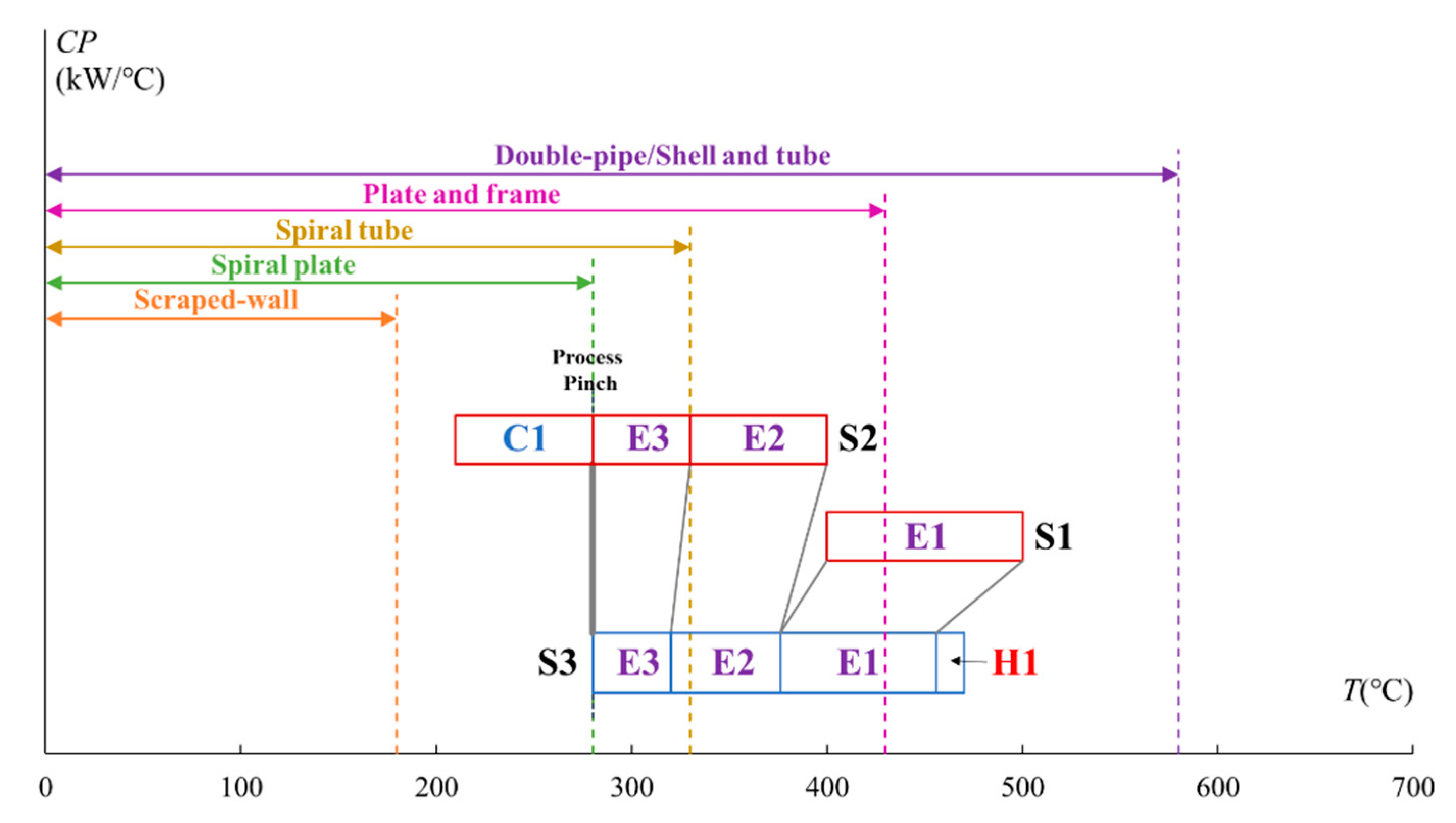
There is another potential option for implementing two double-pipe heat exchangers. The heat transfer area of the double-pipe heat exchanger has a 20 m
2 upper limit. For this case, if only one double-pipe heat exchanger is implemented, then the required heat transfer area is higher than the upper limit for the unit. Considering the relatively low capital cost of double-pipe heat exchangers, it is possible to add two double-pipe heat exchanger units to satisfy both the heat recovery requirement and the heat-transfer area limitation. The Pinch Point for this option is still 280 °C. The range of the normal area of the double-pipe is 0.25–20 m
2. By adjusting the inlet and outlet temperatures of heat exchangers E3 and E2 (both are double-pipe heat exchangers), the retrofit plan of implementing two double-pipe heat exchangers is shown in
Figure 5.
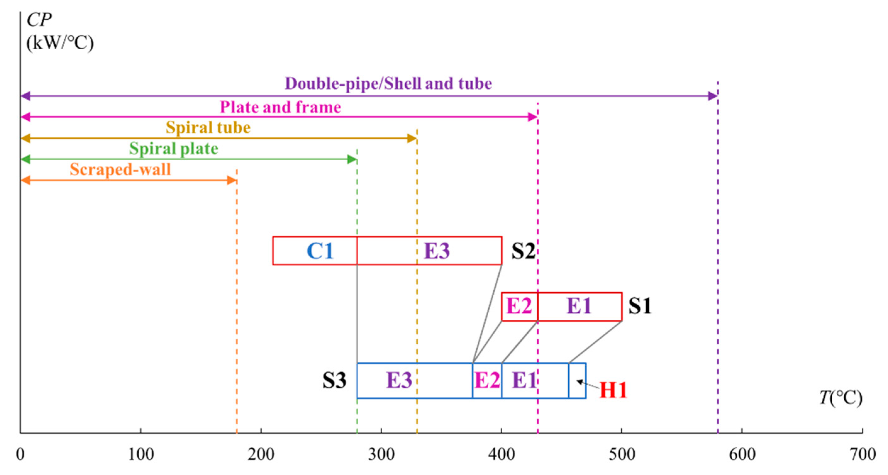
The potential retrofit plan using a plate and frame heat exchanger is considered. As seen in
Figure 2, stream S1 passes through the upper-temperature boundary of the plate and frame heat exchanger, which makes implementing this type of heat exchanger possible. In the retrofit plan illustrated in
Figure 6, the heat of stream S1 is recovered by two heat exchangers. The one in the higher temperature range is a double-pipe heat exchanger, and the other one is a frame and plate heat exchanger.
This step identifies the potential retrofit plans considering the temperature range. When the plans are obtained, then further actions are required to examine other factors, including pressure, area, and corrosiveness. After excluding these inappropriate plans, the next step is calculating the utility and capital cost.
2.3. Utility Cost and Capital Cost Calculation
Besides the temperature and area ranges, the capital cost is another factor that is considered in designing and choosing a heat exchanger. The capital costs of heat exchangers are listed in
Table 3.
Cst, Cdt, Csp, Cst, Cpf are the capital costs of shell and tube, double-pipe, spiral plate, spiral tube, and plate and frame heat exchangers; A is the heat transfer area in m2; P is the shell-side pressure in MPa, and parameters a and b are materials of construction factors when the shell is made of carbon steel and the tube is made of Cr–Mo steel, the values of a and b are 1.55 and 0.05. For the shell and tube heat exchanger with floating head, carbon steel for shell, and Cr–Mo steel for tube, the capital cost calculation can be formulated as Equation (1). For the double-pipe heat exchanger, the capital cost equation for an outer pipe of carbon steel and an inner pipe of stainless steel is formulated as Equation (2). The capital cost of the spiral plate can be calculated by Equation (3). The capital cos of the spiral tube heat exchanger can be calculated by Equation (4). Finally, the plate and frame heat exchanger capital cost can be calculated by Equation (5).
Other fundamental equations used to determine the heat load, the overall heat transfer coefficient,
LMTD, and the heat transfer area are listed as follows.
where
Q is the heat load, kW;
A represents the heat transfer area, m
2;
U is the overall heat transfer coefficient, kW/(m
2·°C);
LMTD represents the logarithmic mean temperature difference, °C. The overall heat transfer coefficient can be calculated by Equation (7) if the inner and outer surfaces of the tube are almost identical. When the wall thickness of the tube is small and the thermal conductivity of the tube material is high, the overall heat transfer coefficient simplifies to Equation (8).
where
hh and
hc are the individual heat transfer coefficients of the connected hot and cold process streams, kW/(m
2·°C);
dxw represents the wall thickness, m;
k represents the thermal conductivity of the material, kW/(m·°C).
The equations for calculating
LMTD and the heat transfer area (
A) are listed in Equations (9) and (10).
where
and
are the inlet and outlet temperatures of hot streams, °C;
and
are the inlet and outlet temperatures of cold streams, °C.
For this illustrative example, as can be observed from
Figure 3 to
Figure 6, the utility cost of all four of these retrofit plans is the same. They can recover an additional 480 kW of heat compared to the existing HEN. The difference among these plans is the selection of heat exchanger types and their capital costs. The comparison of the capital cost for all retrofit plans is shown in
Table 4. For plan 1, three types of heat exchangers (i.e., double-pipe, plate and frame, and shell and tube) are pre-selected in
Section 2.2. The double-pipe can be excluded as the heat transfer area (38.3 m
2) is higher than the upper limit of the area ranges of the double-pipe heat exchanger. The shell and tube heat exchanger is selected for plan 1 because the cost for the plate and frame exchanger is higher than the shell and tube heat exchanger. The total capital cost for the third retrofit plan is the cheapest. Two new double-pipe heat exchangers are selected. Another feasible plan is plan 1. One shell and tube heat exchanger should be implemented. For plan 2, the capital cost for the spiral tube heat exchanger is too high. Although it has a higher maximum bearing pressure, in this example, there is no need to use this type of heat exchanger. The plate and frame heat exchanger used in plan 4 has a relatively high cost for a small heat transfer area, and it is not recommended in this retrofit application.
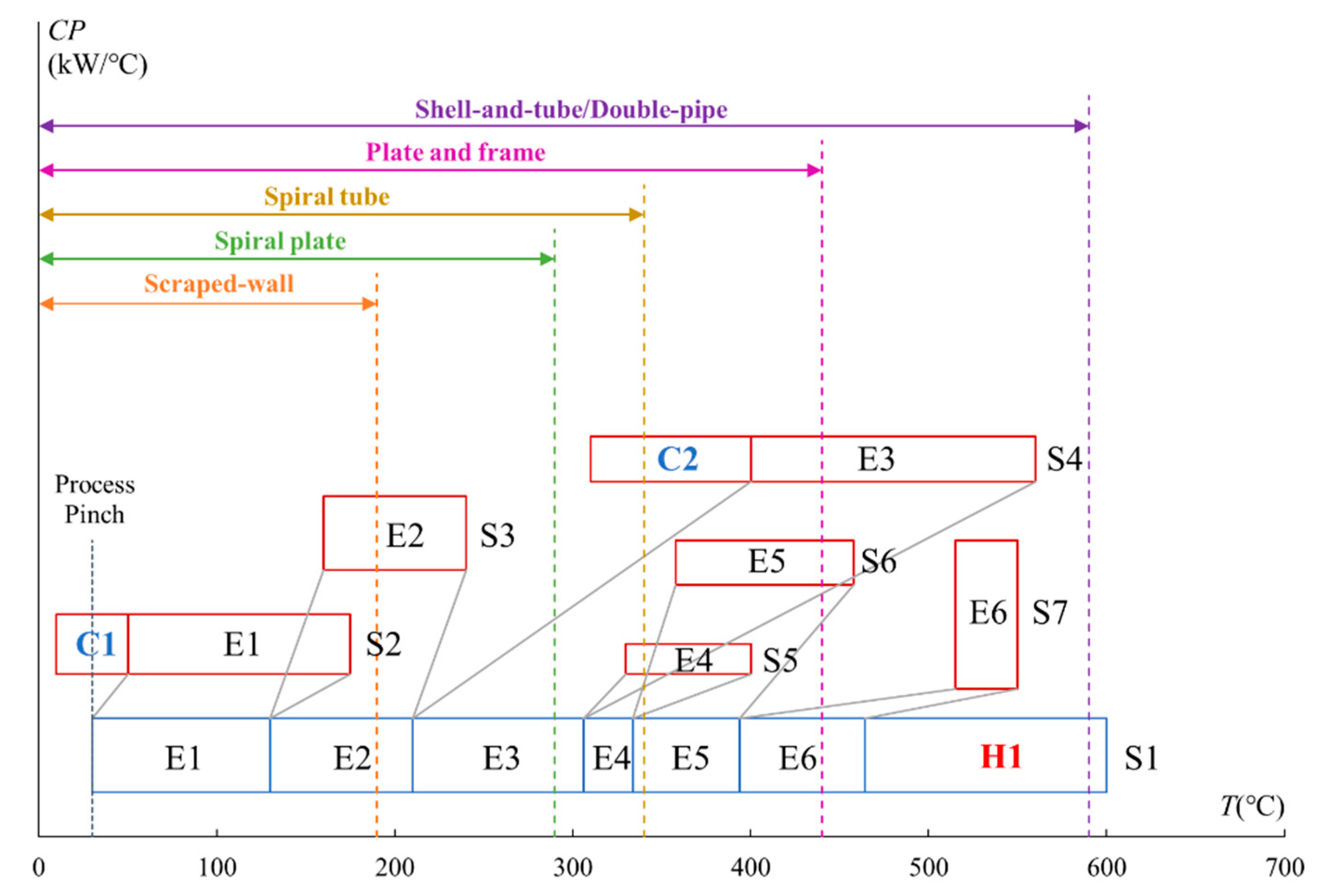
3. Case Study
A case study is used to illustrate the proposed method for HEN retrofit, considering heat exchanger types. The data is obtained from Ref. [
11], and the target temperature of heat exchanger E3 is modified from 370 °C to 410 °C for a better illustration of the method. The case has one cold stream and six hot streams. The cold stream is heated by six heat exchangers connecting other streams. The ΔT
min of this HEN is designed as 10 °C. The stream data for the case study are listed in
Table 5.
Figure 7 shows the SRTGD-STR of the existing HEN. The temperatures of hot streams are shifted. According to this figure, two potential cold utilities can be removed or their power reduced. For cold utility C1, a vertical dotted line on the left side of stream 1 denotes the lowest cold stream temperature at 30 °C. Any hot stream segments spanning to the left of this vertical line can only be cooled by using a cold utility. Cold utility C2 has the potential to be removed as cold stream S1 can still receive the heat from stream 4.
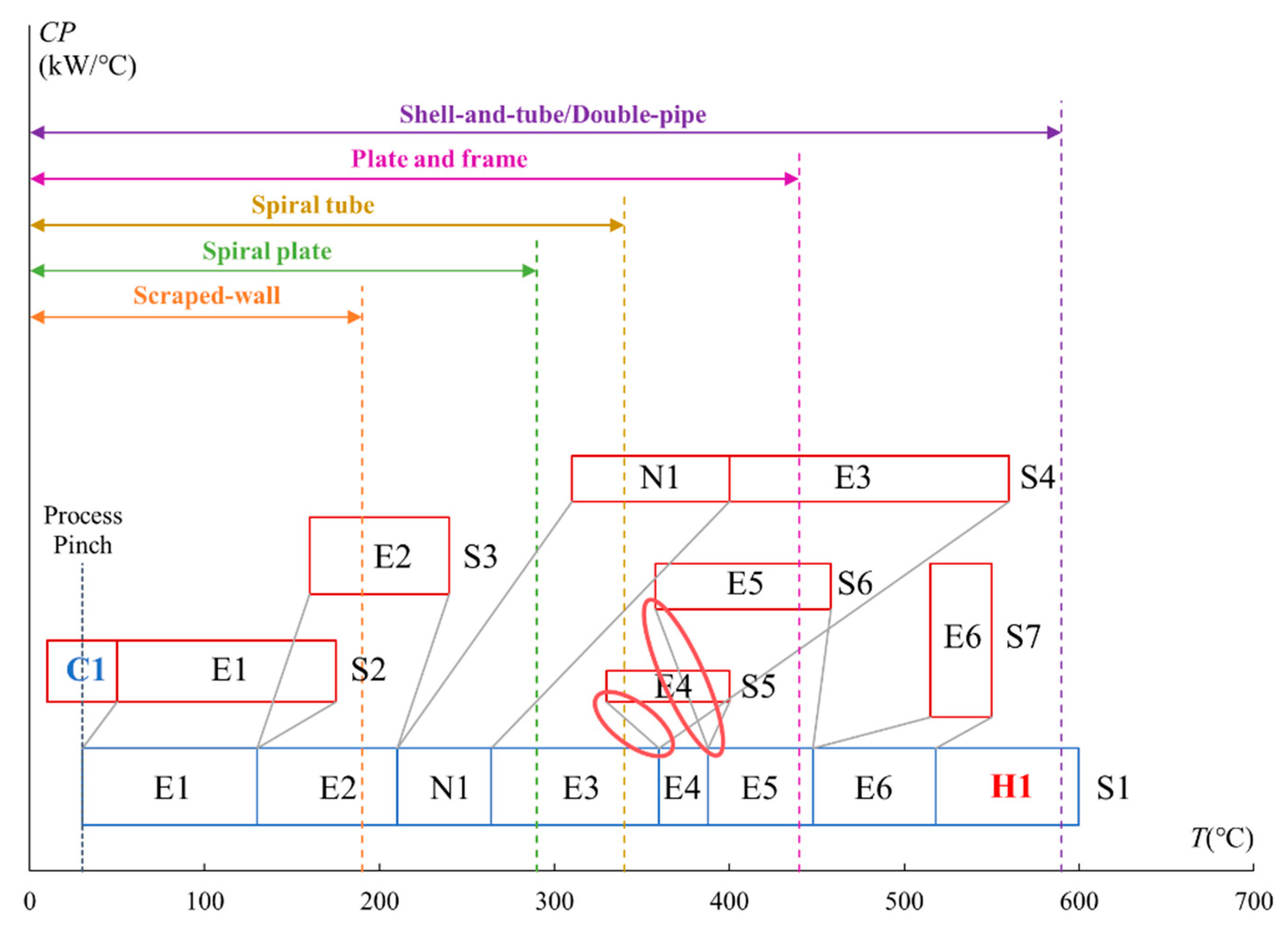
If the heat of stream 4 is fully used for heat recovery and the sequence of the heat exchangers in the existing HEN is not changed, then this retrofit plan would be infeasible, as shown in the red circle marked in
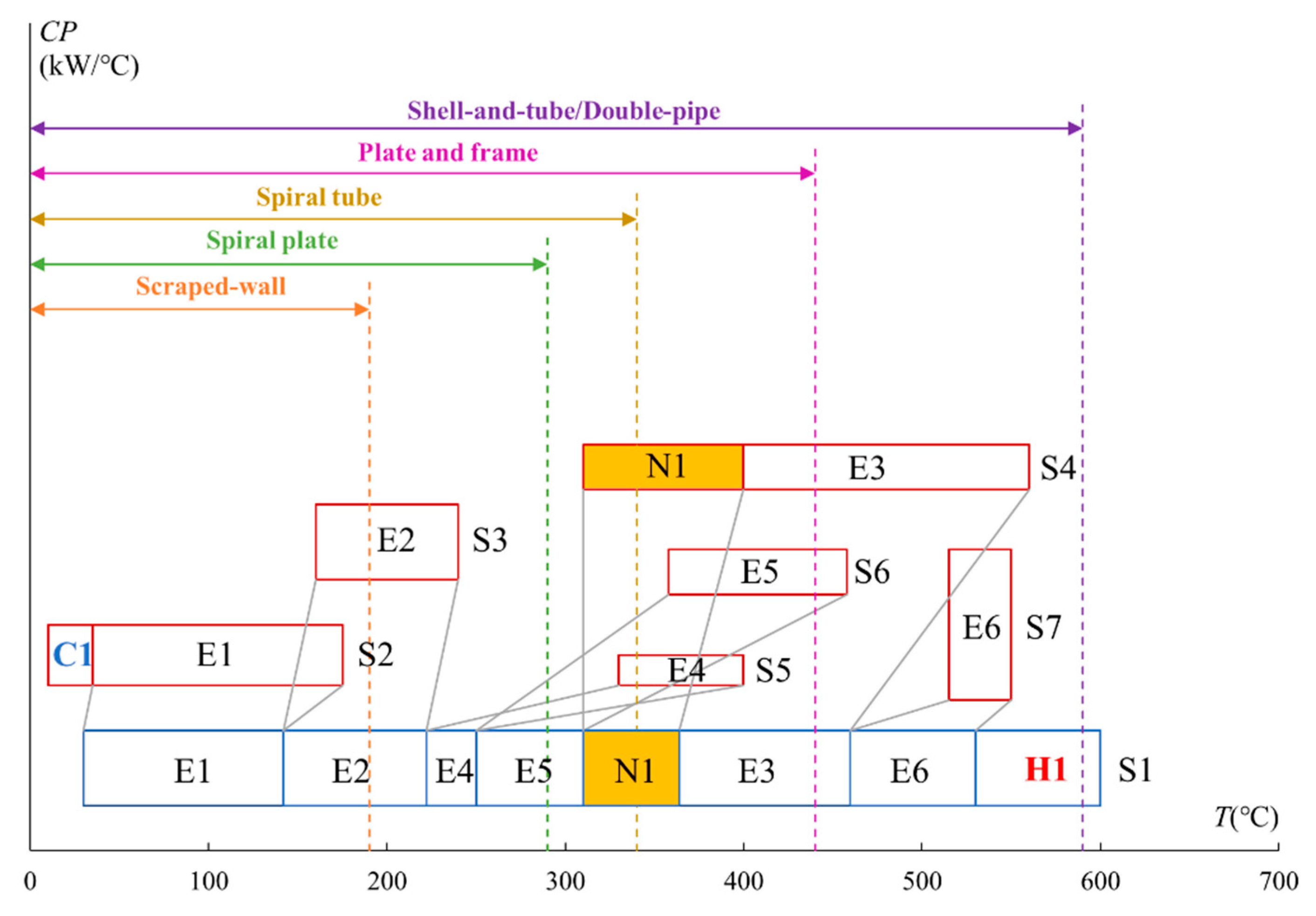
Figure 8. The slopes of links between these two heat exchangers are negative. Re-piping and re-sequencing are needed to utilise the heat. By re-piping heat exchangers E4 and E5 between E2 and E3, the retrofit plan is feasible. The results are shown in
Figure 9.
In this retrofit plan, the cold utility C2 is replaced by a heat exchanger to transfer heat from hot stream S4 to cold stream S1. The sequences of heat exchanger E3, E4, and E5 are changed to not violate the Pinch Rule. This reduces the 270 kW of utility used in this HEN.
In this retrofit process, the heat exchanger types are not considered. However, the capital cost of heat exchangers could also influence the retrofit plan optimisation. For the temperature range of this new heat exchanger N1, there are several choices, i.e., using shell and tube, double-pipe, or plate and frame heat exchangers. The selection of heat exchanger types should also be based on the normal area range of heat exchangers. The feasible and cheapest types should be selected.
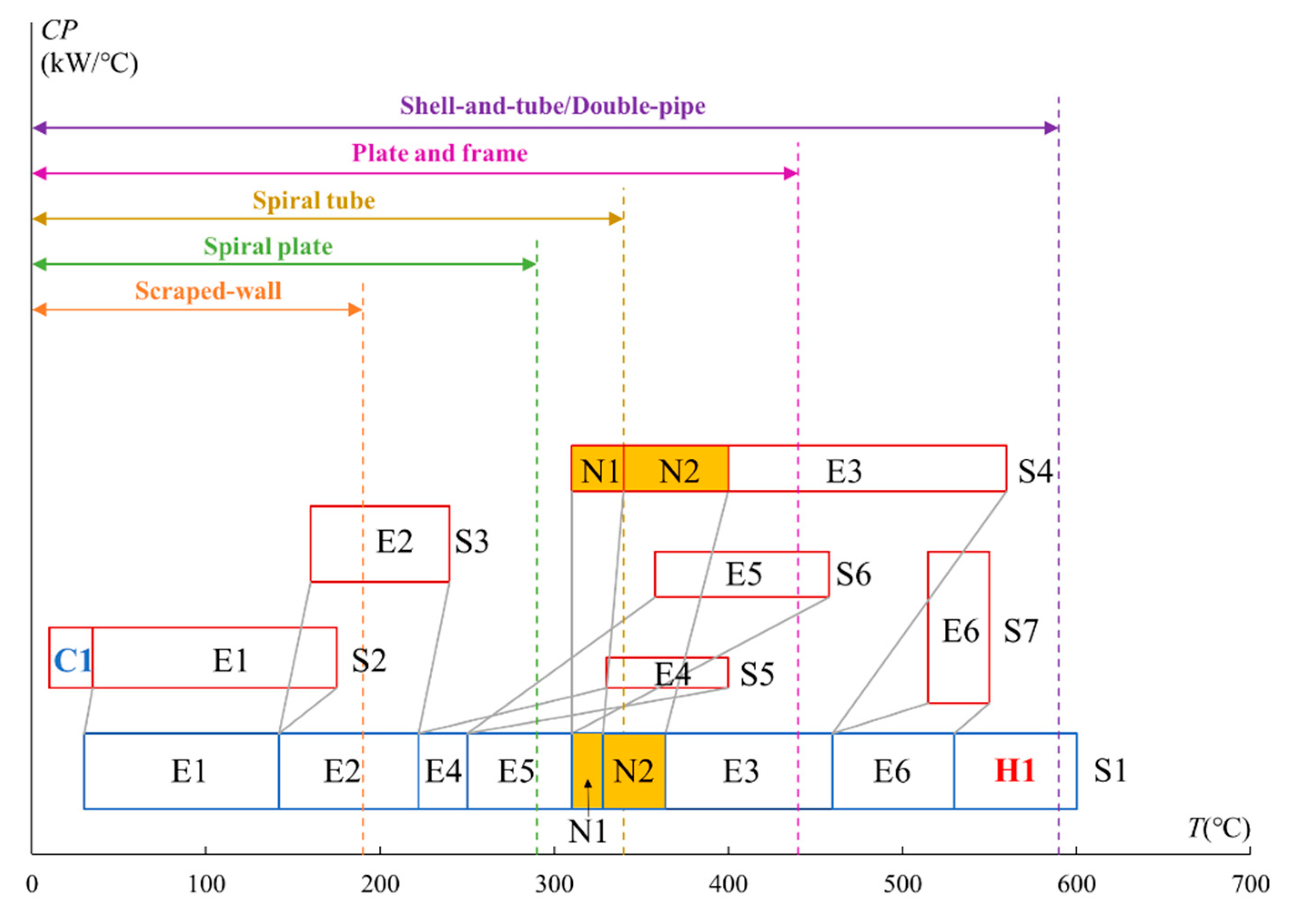
As can be observed from
Figure 7, the temperature range of cold utility C2 crosses over the temperature boundary of the spiral tube, which indicates another option, implementing two new heat exchangers for heat recovery. Another retrofit plan is illustrated in
Figure 10 based on SRTGD-STR considering this possibility. In this plan, heat exchangers E4 and E5 on the cold stream S1 are still moved to the left side of E3, and two new heat, N1 and N2, are implemented between E5 and E3 on S1.
Under these circumstances, there are several choices about the heat exchanger types. The following four combinations can be selected, both shell and tube heat exchangers, both double-pipe heat exchangers, both plate and frame heat exchangers, or one double-pipe and one spiral tube. All these retrofit plans are listed in
Table 6, and their capital costs are calculated according to equations provided in
Section 2.3.
The results (
Table 6) show that the feasible and cheapest retrofit plan is using two double-pipe heat exchangers for heat recovery. Its capital cost is 19.9 k
$. The utility cost saving of all these seven solutions is the same. An additional 270 kW of heat can be recovered by the new heat exchangers, which saves 10.7% of the maximum potential for heat recovery (2,520 kW) of this HEN. Although solution 2 has the minimum capital cost, its heat transfer area is 27.9 m
2. It is higher than the normal area range of the double-pipe heat exchanger, which makes this plan infeasible. The plan implementing two plate and frame heat exchangers has the highest cost. For a relatively small heat transfer area, the double-pipe heat exchanger is the most recommended as it has an advantage in the cost. For a larger heat transfer area, the most economical option could be the shell-and-tube heat exchanger.
4. Conclusions
This paper develops an Extended Grid Diagram named SRTGD-STR by considering the shifted temperature range of heat exchangers for HEN retrofit design. It inherits the advantage of SRTGD for HEN information (topology and stream data) illustration and easy retrofit options identification. The extended method also considers the types and capital costs of heat exchangers, which makes the retrofit application more practical. Six types of widely used heat exchangers are considered, and their shifted working temperature ranges are coupled in the diagram.
By using the novel SRTGD-STR, the retrofit plan can be easily determined. It can provide insight into the identification of the Process Pinch and Network Pinch. The combination of the shifted temperature ranges of different types of heat exchangers and the grid diagram can help engineers to identify potential HEN retrofit plans with the consideration of heat exchanger types and illustrate these plans visually. The illustrative example and case study show the advantages of using this tool in the retrofit process. The case study shows that an extra 10.7% of heat can be recovered by adding additional heat exchangers for the studied HEN. In addition, seven solutions can be identified by the proposed SRTGD-STR. The easy identification of these solutions could help the designers compare the retrofit plans and make a wiser decision. The correct selection of heat exchanger types can help to achieve a relatively lower capital cost.
Future research should further consider other issues such as phase change, freezing risk, and material cost in the retrofit design to extend the application field of this tool. Moreover, this approach can be further developed by considering the uncertainty temperature variation margins to make the retrofit plan adapt to a wider range of working conditions. Although the SRTGD-STR could identify retrofit plans according to the insight of thermodynamics, there still exists some potential to minimise the sum of the energy cost and investment cost by a trade-off of these two costs.


