1. Introduction
In recent years, the idea of a smart grid, which features distribution generations (DGs) and intelligent energy management, has been very popular. The high penetration of DGs is a suitable solution to energy and environmental problems. However, DG faces many challenges, like volatility, randomness, and uncontrollability, when connected to distribution networks [
1,
2]. When a large scale of power electronic interfaces is connected to the distribution networks, there will be other problems such as uncertain power flow, energy optimization scheduling and so on [
3]. Besides, the traditional distribution grid lacks energy management equipment and an information support system, making it difficult to guarantee flexible access to a distributed power supply, storage energy, flexible load and a clean energy system (combined cooling, heating, and power, CCHP) [
4]. This restricts the local consumption of renewable energy and the interaction between end-user equipment.
A power router (PR) provides a possible solution to the problems above [
5,
6]. The first future version of a power router also called an energy router, is proposed by the North Carolina State University under a project entitled the Future Renewable Electric Energy Delivery and Management System (FREEDM) [
7]. In recent years, the architecture of the power router has been discussed widely [
8,
9,
10]. In Ref. [
10], Phuong implements a smart power router in an agent-based active distribution network, which can flexibly integrate network areas and optimally manage power flows.
Researchers have also done a lot of work on the power router’s power electronic topologies [
11,
12,
13,
14,
15,
16,
17,
18,
19]. In Ref. [
11], Antonio presents an energy router that dynamically controls energy flow using a full-bridge structure. In Ref. [
12], Brian introduces the “Smart Green Power Node” concept for power router. However, in this topology, photovoltaic panels and batteries have their specific converters, which means that the converter is not generally used. This will add to the cost of the system. In [
13,
14], Takahashi proposes a power router using power line communication and power Metal-Oxide-Semiconductor Field-Effect Transistor (MOSFET) to realize the routing among loads. Takahashi’s topology only arranges the route of power but doesn’t realize the interconnection among different voltage levels and type systems. In Ref. [
15], Girbau-Llistuella introduces the architecture of an intelligent distribution power router with a battery used in rural distribution. It can connect DC equipment to an AC grid, but the power router’s port property is fixed. In Ref. [
16], Kordonis used a matrix converter and several power routers to connect utility grids and microgrids. The router only rearranges the power and the matrix converter holds the duty of converting voltage. This increases the cost of a system. In Refs. [
17,
18], the proposed power routers’ topology is based on a dual half-bridge and high-frequency transformer (HFT) respectively; however, in [
19], Ren pointed out the problem that HFT structure is so complicated and expensive that it is difficult to be used by manufacturing. Ren proposes a power router topology based on the conventional three-phase inverter and DC-DC converters instead. However, the topologies mentioned above cannot achieve the route of ports, which means a DC port can only be used for DC applications and it is the same for AC ports. Therefore, there will be idle ports if the load or generator type doesn’t meet the port requirement, which will decrease economic efficiency.
This paper proposes an alterable structure power router (PR) topology to address the port problem. Not using the HFT structure, the alterable structure power router is cheaper and easier to manufacture. The PR composes two major parts, which are the electrical part and the standard information interface part. The electrical part contains a converter and a filter. In the first part, the topology and operation principles of PR is introduced in detail. Based on the operation analysis of the PR, the mathematic model of the power router is established. The relationship between the converter output voltage and the switch state is analyzed. According to the mathematic model, the PR output voltage and current are analyzed. The ability of bidirectional power flow as well as general AC and DC port is illustrated using the mathematic model. Control structure and switching process are introduced to show the practicability and operation method of PR. The switching process guarantees a safe and fast transform among different working modes. This also enables the PR to give access to a variety of equipment. With the proposed PR topology, general AC and DC port, bidirectional power flow and plug-and-play are realized. Finally, the simulation and experiment results prove the good steady-state and dynamic performance of the proposed power router topology.
2. Topology and Operation Principles
The power router has four advantages with respect to design and application.
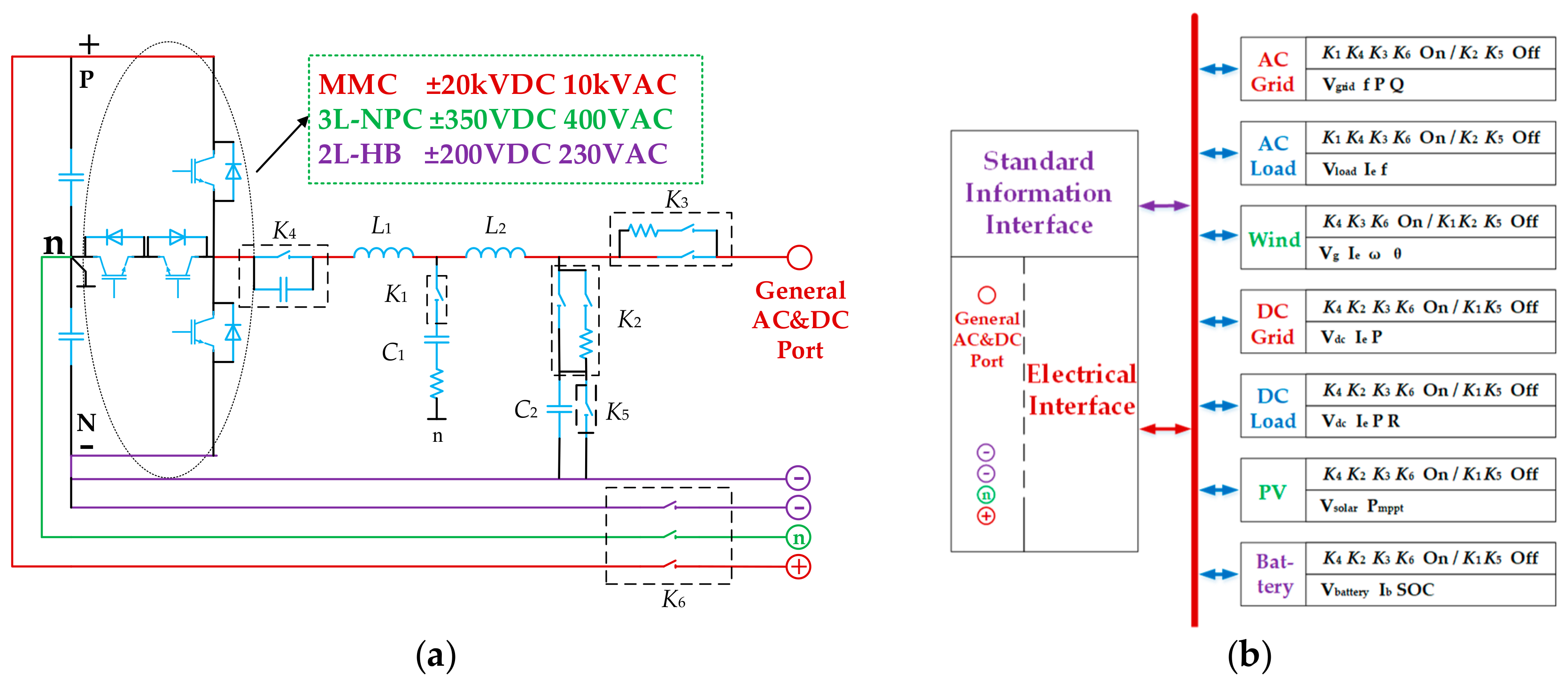
First, to reduce the hardware cost and design power router for different situations, the PR has an alterable converter structure according to the voltage level. The power and voltage level of DC micro-girds vary from different values. There are three typical kinds of AC voltage levels which are 230 V, 400 V, and 10 kV. The topology of a single-phase structured PR is shown in
Figure 1a. It contains a converter and a filter. According to the voltage level of the DC side, the converter topology can be chosen from modular multilevel converter (MMC), three-level neutral point clamped (3L-NPC) and two-level half bridge (2L-HB). MMC is suitable for high voltage and power applications [
20], while 3L-NPC [
21,
22,
23] and 2L-HB are typically applied in medium and low voltage situations.
Second, the power router’s power can flow bi-directionally. The switch devices in the converter are IGBTs with antiparallel freewheeling diodes, which enables the power to flow in both directions.
Third, considering both the bandwidth and transient response, the filter can realize plug-and-play together with the information interface.
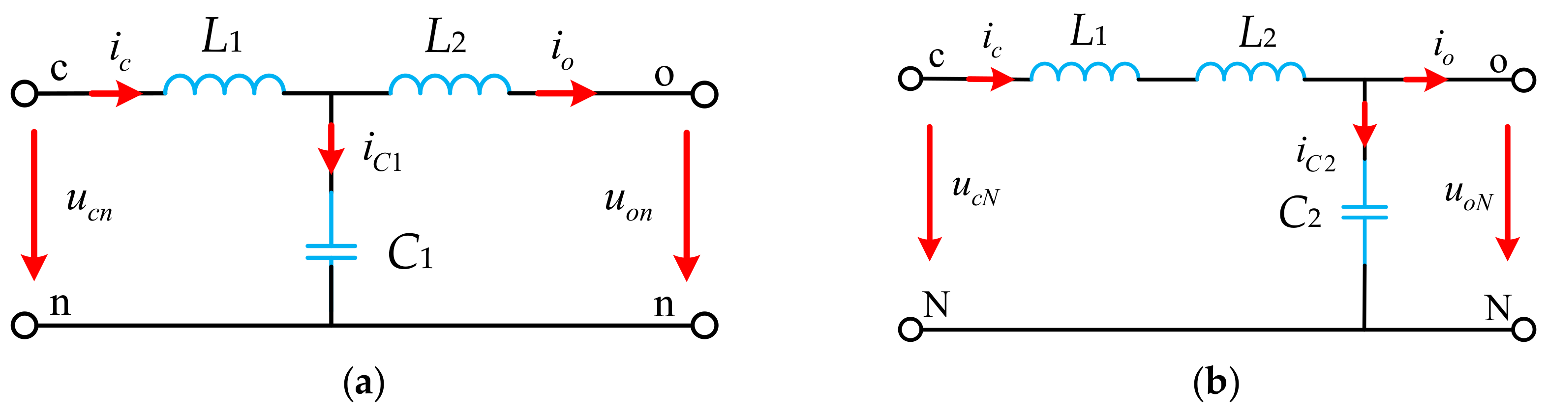
Fourth, the power router has a general AC and DC port. The filter part of the PR can change between LCL and LC, in which L1, C1, L2 form the LCL filter and L1, L2, C2 form the LC filter. In the case of LCL filter, the converter outputs an AC voltage between the port and neutral point; while in the case of LC filter, the converter outputs a DC voltage between the port and negative bus, which makes the port a general AC&DC port. K1, K4 are AC relays and K2, K3, K5, K6 are DC relays.
The design of general AC and DC ports also decreases cost and does not influence power router’s performance. Compared to independent AC or DC converters, this topology adds some relays to realize both AC and DC port. When operating in a steady state, this topology is the same as independent converters for AC or DC ports. In detail, when operating in AC mode, the switches form LCL filter and the topology operates the same as traditional 3L-NPC. When operating in DC mode, the switches form the LC filter and the topology operates as a half bridge converter. Therefore, the performance will be almost the same as independent converters, disregarding the power loss on relays, which is not large. The cost will be higher than independent converters in the part of relays, but relays are not too expensive.
Table 1 lists the type, price, and parameters of the relays we use in the experimental prototype. Referring to
Table 1, the total cost of extra relays is 60 yuan each phase since
K3,
K4 and
K6 are necessary even for independent AC port. The total cost of our experiment prototype is about 3500 yuan, including Digital Signal Processor (DSP), Field-Programmable Gate Array (FPGA), inductors, capacitors, heat sink, Insulated Gate Bipolar Transistor (IGBT) modules, etc. To conclude, adding extra relays costs 180 yuan for 3 phases and the total cost increases for about 2.8%, from 3500 yuan to 3680 yuan, which is much cheaper than building two independent converters.
Figure 1b shows the interfaces and the applications of the PR. The PR provides a standard information interface and an electrical interface. The standard information interface is used to transfer information to PR. The electrical interface has three input ports, which are for the positive and negative bus, as well as a neutral line. It also has three output ports, one is the general AC & DC port, the other two are the reference ground for the port, which is neutral line for AC condition and negative bus for DC condition. Due to the ability of the general AC & DC port, PR is suitable for typical renewable energy applications such as wind turbine and photovoltaic (PV) panels. In addition, it can be used in battery applications to realize a power conversion system. Besides, it is suitable for typical conditions such as AC grid, DC grid, AC load, DC load.
Table 2 shows the detailed information of
Figure 1b. In
Table 2, the on/off describes the state of relays in a certain application. The variables such as V
grid, f, P, Q are the information transferred to PR.
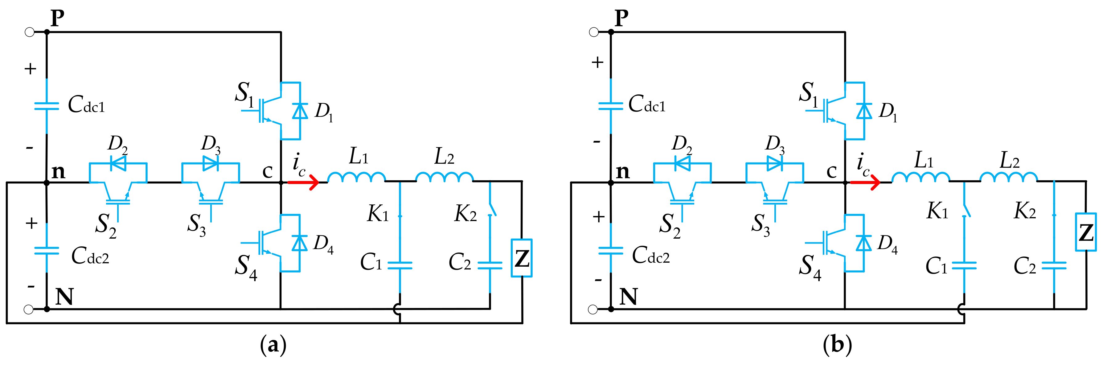
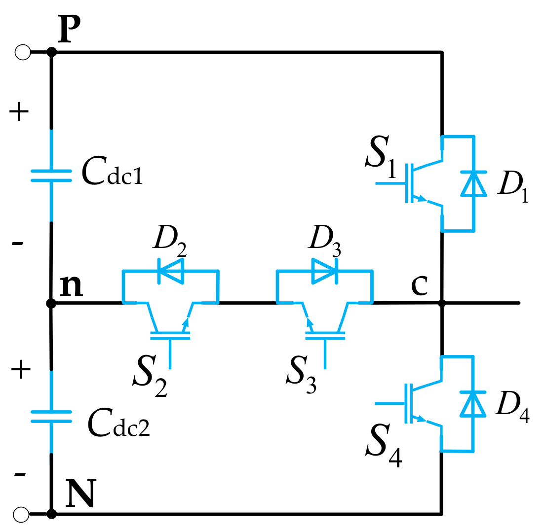
Due to the following reasons, we select 3L-NPC shown in
Figure 2 as a typical solution to verify our topology. First, 3L-NPC is commonly used in medium voltage situations and it’s a pretty mature topology. Our lab has built a mature prototype and it’s easier to realize the proposed topology based on this prototype. Second, our lab doesn’t have the experimental platform for MMC because it’s used in very high voltage conditions. Third, HB topology doesn’t perform very well in AC applications as 3L-NPC due to the difference in output voltage levels. Fewer voltage levels will cause larger output current ripple and larger Total Harmonic Distortion (THD).
The PR operates differently in AC and DC modes. The difference of
Figure 2a,b lies in that under AC mode, the filter is switched to LCL filter, the DC filter capacitor C
2 is excluded from the circuit using a switch; under DC mode, the filter is switched to LC filter, the AC filter capacitor C
1 is excluded from the circuit using a switch.
The relationship between the output voltage and switching states of the converter is analyzed. There are
switch states in total, in which only 8 states are reasonable. When
S1 and
S4 are on,
Cdc1 and
Cdc2 are short-circuited. When
S1 and
S3 are on,
Cdc1 is short-circuited. When
S2 and
S4 are on,
Cdc2 is short-circuited.
Si (
i = 1,2,3,4) is defined as the switching state:
The reasonable switch states, output voltage and charging state of capacitors of PR under AC mode are listed in
Table 3. In
Table 3,
Udc1 refers to the voltage of
Cdc1 and
Udc2 refers to the voltage of
Cdc2.
When the PR operates in AC mode, from
Table 3, a rule can be observed that when
S1,
S3 are complementary and
S2,
S4 are complementary, the output voltage is definite. The uncertain voltage level happens when
S2,
S4 or
S1,
S3 are both zero. These situations need to be avoided. By sticking to the rule, the relationship between the output voltage and switching states can be simplified as:
where
,
,
are the output voltage of the converter, DC voltage of the upper and lower capacitor.
From Equation (2), it can be seen that under AC mode, can be fundamentally a sinusoidal wave if the switch state of S1 and S4 are realized through the compare of a sinusoidal modulation wave and two high-frequency triangle carrier waves.
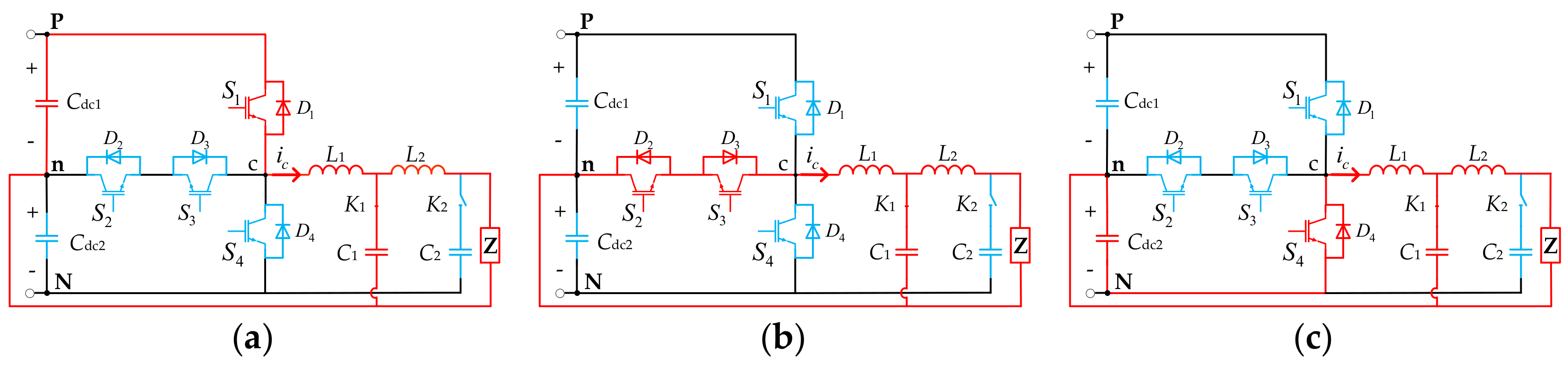
Figure 3 shows the current path of T-type three-level converter in three level conditions:
From
Figure 3, it can be seen that under AC mode, the voltage stress of
S2 and
S3 is half of the capacitor voltage, which is one-fourth of the DC voltage, while the voltage stress of
S1 and
S4 is half of the DC voltage. The current stress is the same for all the switches.
Referring to
Table 3 and
Figure 3, in AC mode, the capacitor currents are directly related to the converter output currents as follows:
where
idc1,
idc2 is the current flow into
Cdc1 and
Cdc2,
ic is the converter output current.
The reasonable switch states, output voltage and charging state of capacitors of PR under DC mode are listed in
Table 4.
When the PR operates in DC mode, from
Table 4 it can be seen that there are still three levels. However, using the output voltage of
Udc2 is easy to result in voltage unbalance between
Cdc1 and
Cdc2. To avoid this situation, this switch state is not adopted, so in DC mode, PR operates as a two-level converter, which is the same as a half-bridge converter. In this mode,
S2=
S3=0, and
S1 and
S4 are complementary. The relationship between the output voltage and switching states can be expressed as:
From Equation (4), it can be seen that under DC mode, can be fundamentally a DC wave if the switch state of S1 is realized through the compare of a DC wave and a high-frequency triangle carrier wave.
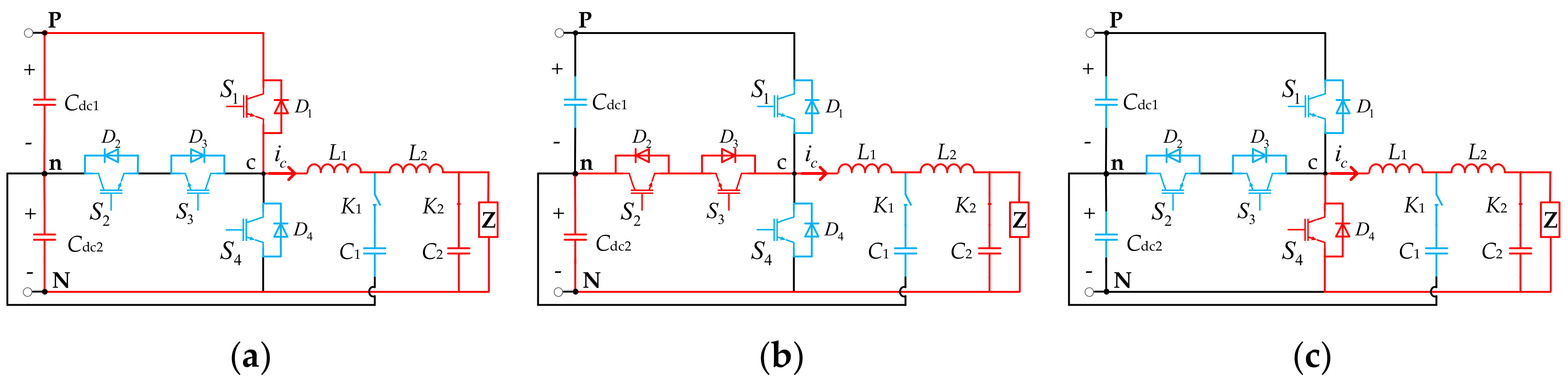
Figure 4 shows the current path of T-type three-level converter in three level conditions:
From
Figure 4, it can be seen that under DC mode, the voltage stress of
S1 and
S4 is half of the DC voltage. The +1 level shown in
Figure 4b is not adopted due to the possibility of unbalance between
Udc1 and
Udc2. The current stress is the same for
S1 and
S4.
Referring to
Table 4 and
Figure 4, in DC mode, the capacitor currents are directly related to the converter output currents as follows:
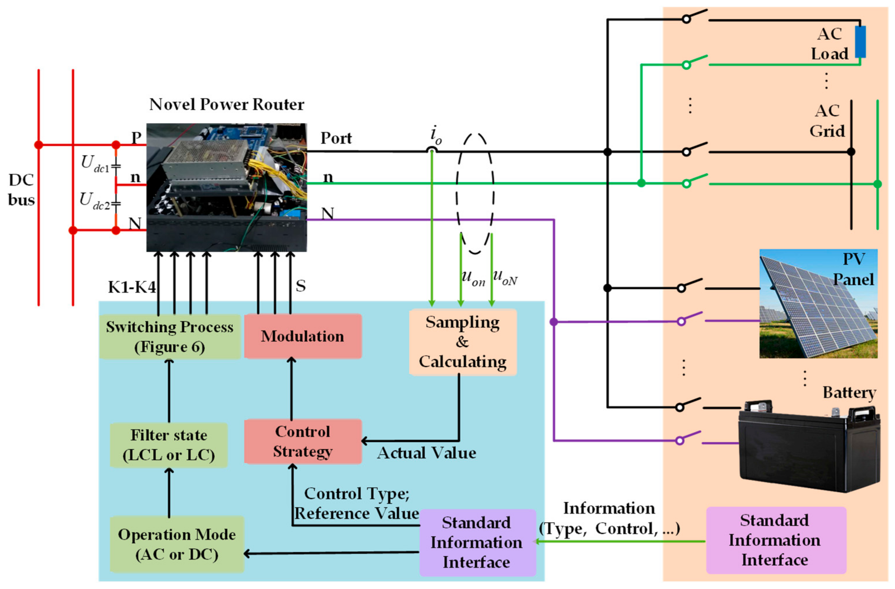
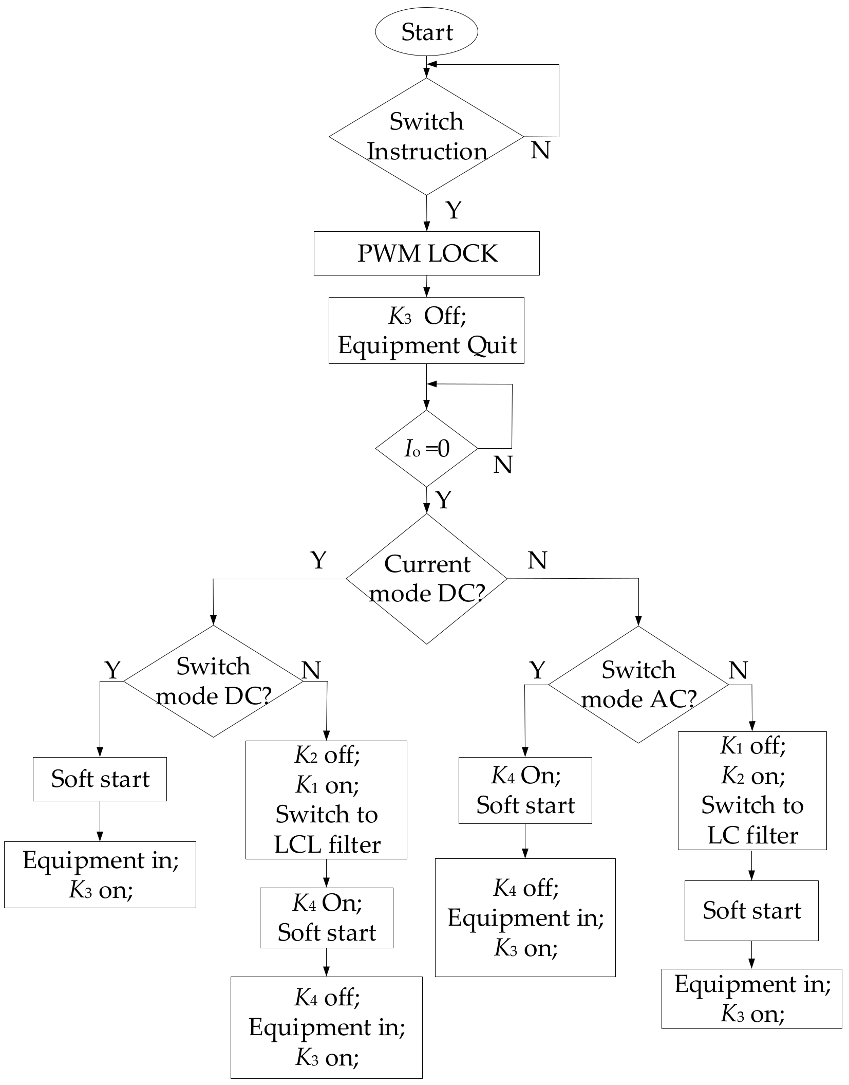
4. Control Structure
Figure 8 shows the PR control structure. Electrically, the PR connects to the DC bus at the DC side and to various kinds of equipment such as AC load, AC grid, PV panel and battery at the output side. The equipment has their own Standard Information Interface to communicate with the power router. In this section, information such as equipment type and parameters, control targets and strategies are transferred from the equipment to the power router. Then, the PR will judge the operation mode and control strategy. After that, the filter state is decided and the switching process is realized. The detailed switching process is shown in
Figure 9. Meanwhile, the control strategy is chosen and carried out together with the sampled port voltage and current value. Modulation voltage is generated in this part and used to generate the switch states to control the output waveform of the PR.
Figure 9 shows the switching process to prepare the port. The transient switch process is also designed to avoid arcing.
First, PR will check the switching instruction in a 1kHz interruption. When the switching instruction is confirmed, PR will lock the PWM and turn off the output switch K3, check the output current Io to make sure the port is idle for use. During the switching process, arcing may occur when switching off K3 if the output current Io isn’t zero. But since PWM is locked, the energy that causes arcing is limited. There won’t be serious problems.
Second, it will change the filter state through the filter relays K1, K2 according to the type of the equipment. Since there is no current on the inductor L1 and L2 now and the equipment is quit, turning on/off the relays won’t cause arcing. In addition, because the process will be first turning off one of the relays and then turning on the other, there won’t be circulating current between the capacitors C1 and C2, thus no arcing will happen.
Third, the soft start process will begin based on the type of the equipment. K4 is used for AC soft start while K3 is used for DC soft start. During this process, arching won’t happen since soft start only provide a output voltage but not current.
Finally, the PR will run in steady state.
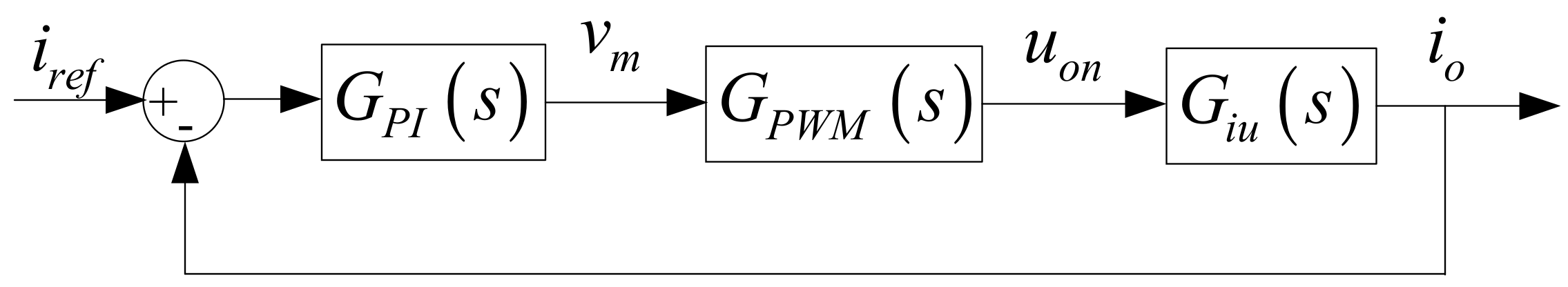
In AC mode, control strategy is designed using Equations (16) and (17), which is shown in
Figure 10.
The closed loop transfer function of this control strategy is as follows:
where
,
,
.
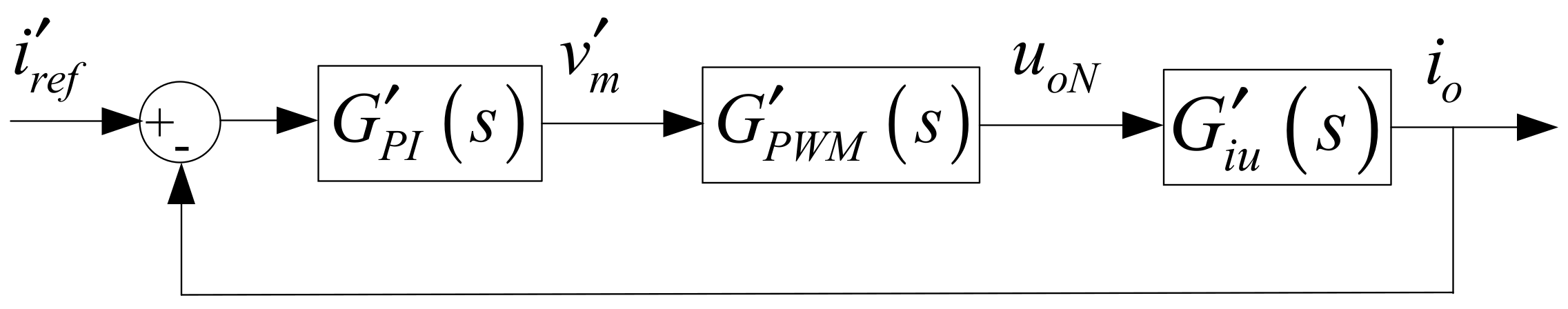
In DC mode, control strategy is designed using Equations (18)–(20), which is shown in
Figure 11.
The closed loop transfer function of this control strategy is as follows:
where
,
,
.
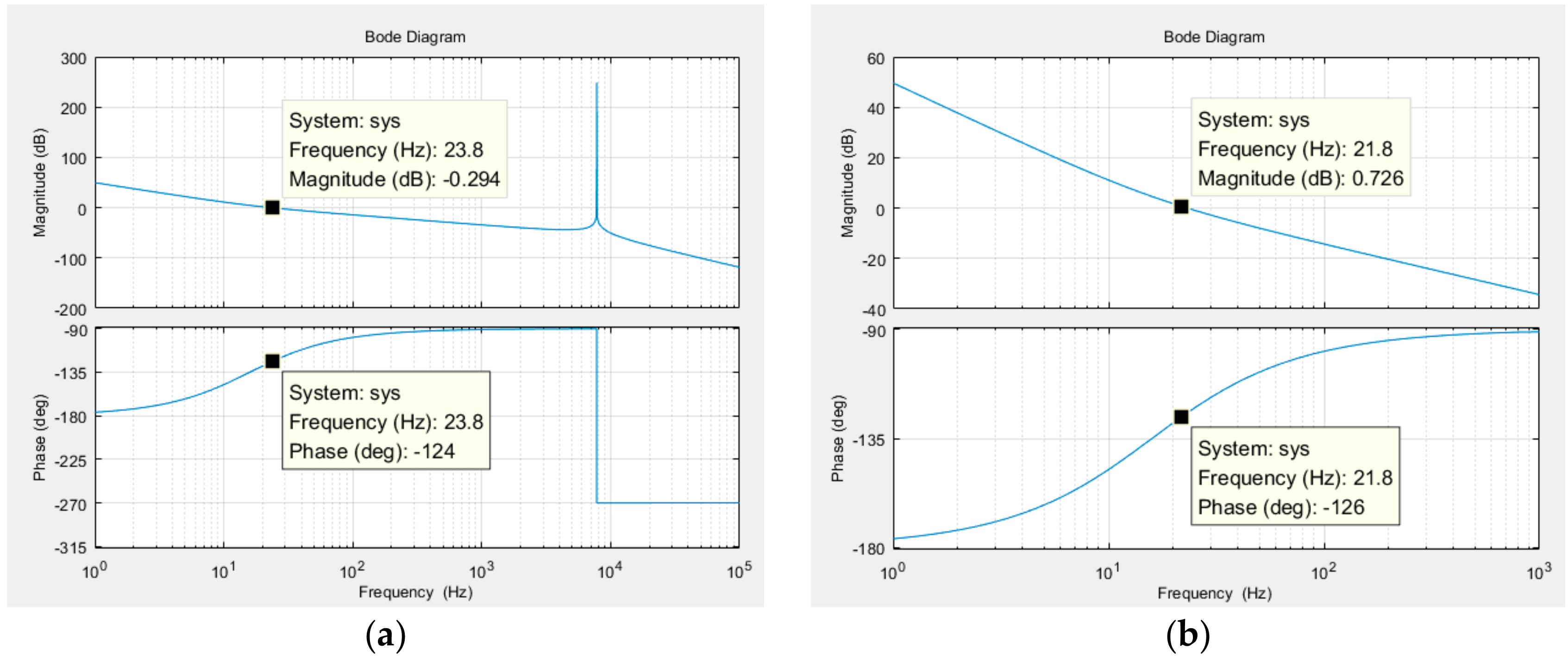
According to the parameters in
Table 5, the controller parameters of the open loop of AC mode current control and DC mode current control can be designed based on the principle of eliminating transfer function’s poles, which will help improve the steadiness of control. The Bode plot is shown in
Figure 10. The controller parameters of AC mode is
kp = 0.0001,
ki = 0.03; the parameter of DC mode is
kp′ = 0.0001,
ki′ = 0.01.
From
Figure 12, it can be seen that the phase margins of both controls are larger than 45°. Meanwhile, the pulse frequency of AC mode control is about 8 kHz and the switching frequency is 15 kHz. Therefore, the system is stable.
5. Simulation Results
The PR topology is simulated in MATLAB/Simulink.
Table 5 shows the PR simulation parameters and
Table 6 indicates the parameters of specific working states.
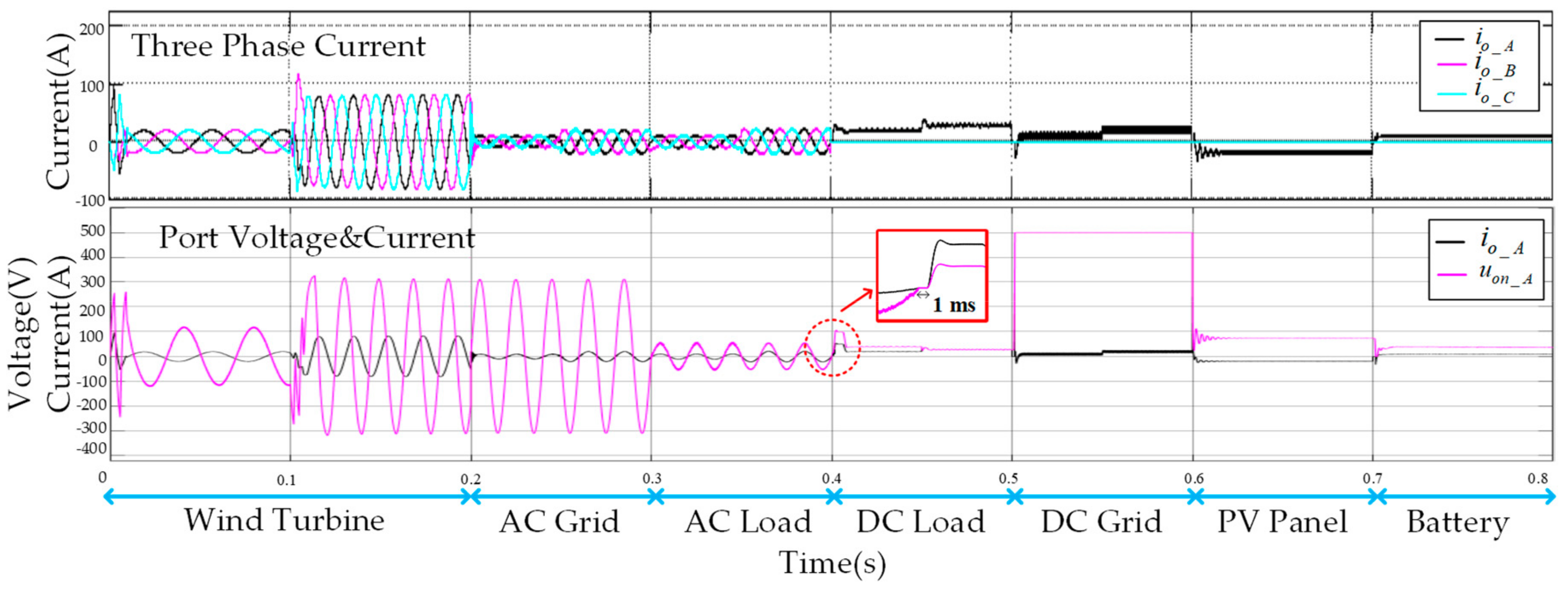
Figure 13 shows the simulation result that the power router works under different states according to the equipment that is connected. In the simulation, it is assumed that the PR’s switches can be put in and cut off at a very fast speed so that the switching time can be ignored.
In
Table 6, for renewable energy like wind turbine and PV panel, maximum power point tracking (MPPT) is the typical control strategy [
24,
25], so MPPT is tested in the simulation. For a traditional AC grid, AC load, DC load and DC grid, typical active power and reactive power control is adopted. For battery applications, charge current is calculated according to the battery’s state of charge (SOC).
In AC mode, PD-PWM is adopted. In 0–0.2 s, PMSM is connected, the power router works at AC mode. The rotor speed tracks the optimal speed to realize MPPT. The output voltage is filtered to show a better relationship between output current and voltage. At 0.1 s, there is a step in the wind speed. At 0.2 s, PMSM quits and AC grid requires connecting in. In 0.2–0.3 s, the power router transfers power between DC microgrid and AC grid. Power step happens at 0.25s. At 0.3 s, AC grid quits and AC load is connected. In 0.3–0.4 s, the power router transfers power from DC microgrid to the loads. At 0.35 s, the load is cut half, so the current changes to meet constant power output. At 0.4s, AC load quits and DC load is connected in.
In DC mode, to fully use the three-phase ports, they are connected together and phase-shift PMW(PS-PWM) is adopted. The phase shift of the three carrier waves is 0°, 120°, and 240° respectively. This modulation method has the advantages of lowering the output current ripples and smoothing output voltage. In 0.4–0.5 s, the power router works in DC mode and uses the same port to transfer power to the DC load. At 0.45 s, the load is cut half to check the constant power control effect. At 0.5 s, DC load quits and DC grid is connected. Power step happens at 0.55 s. At 0.6 s, PV is connected. MPPT is realized in 0.6–0.7 s. At 0.7 s, PV quits and a battery is connected. In this period, constant current control is applied according to the SOC of the battery.
In the stage of AC switching to DC, fast switching is realized. By locking the converter first, then releasing energy in inductors, unlock the converter and pre-charge for next state, the switching is safe and fast. From
Figure 11, it can be seen that switching is realized in 1ms, which is very fast. The simulation results prove the feasibility of fast switching and that the surge current or voltage is small.
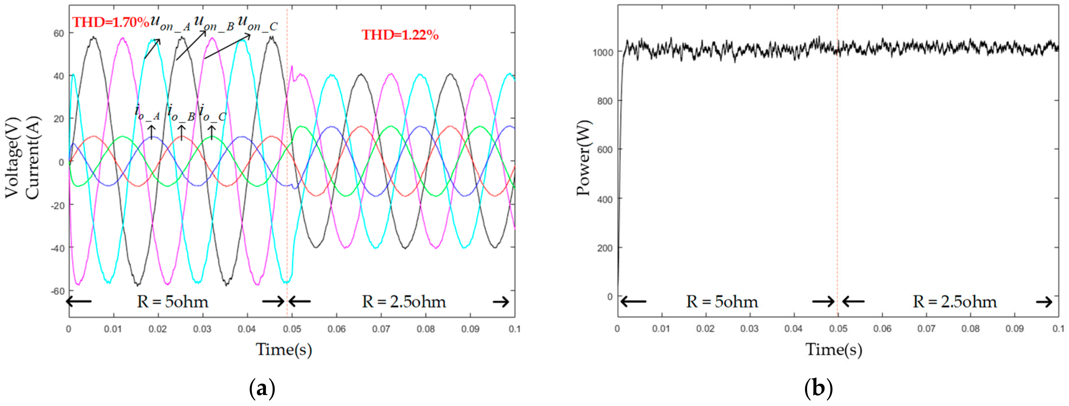
Figure 14 shows the detailed port voltage, current, and power in AC load mode. Constant power control introduced in
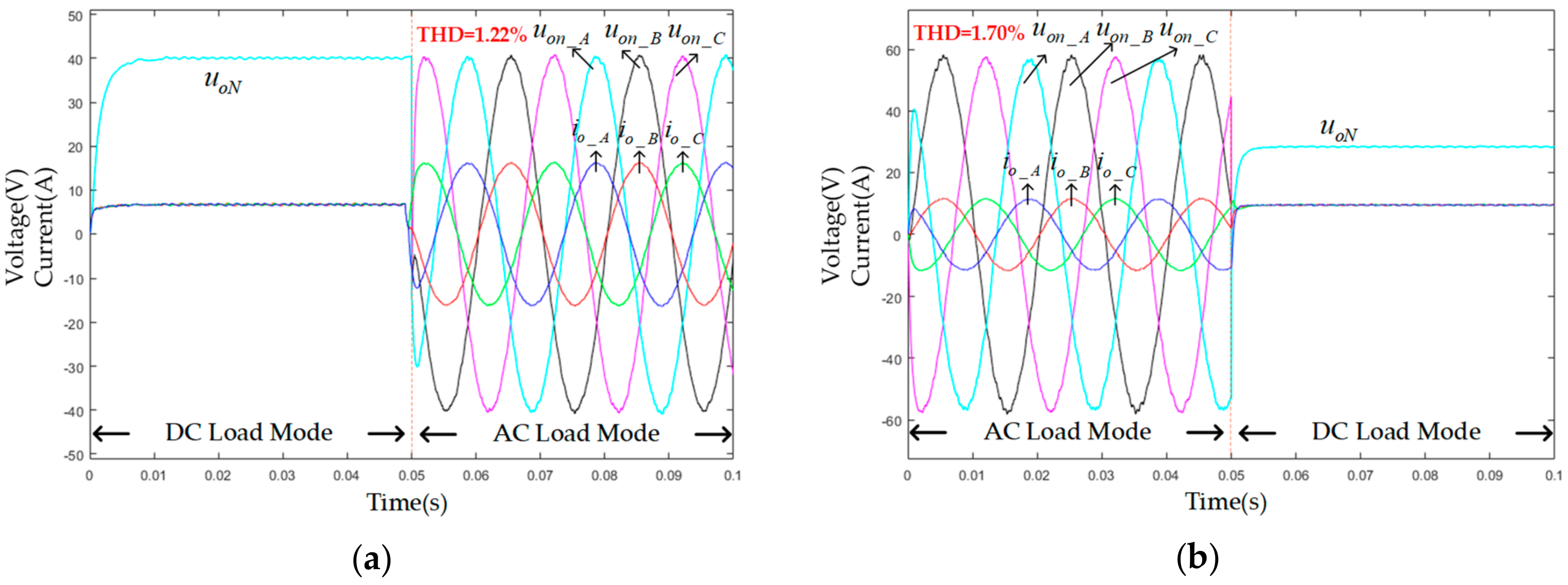
Figure 10 is applied during this period to control the active power to be 1 kW and the reactive power to be 0 Var. At 0.05 s, the load drops from 5 Ω to 2.5 Ω.
Figure 14b shows the control speed and accuracy of this control strategy.
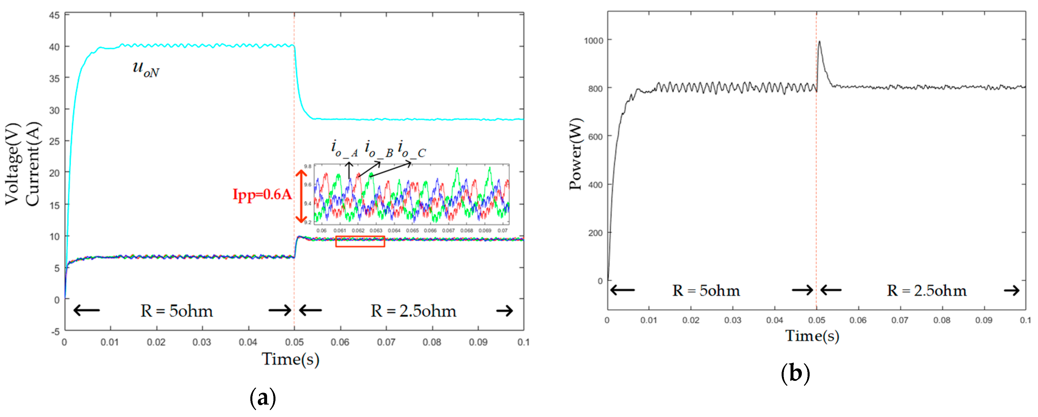
Figure 15 shows the detailed port voltage, current, and power in DC load mode. Constant power control introduced in
Figure 11 is applied during this period to control the active power to be 800 W. At 0.05 s, the load drops from 2 Ω to 1 Ω. The power in
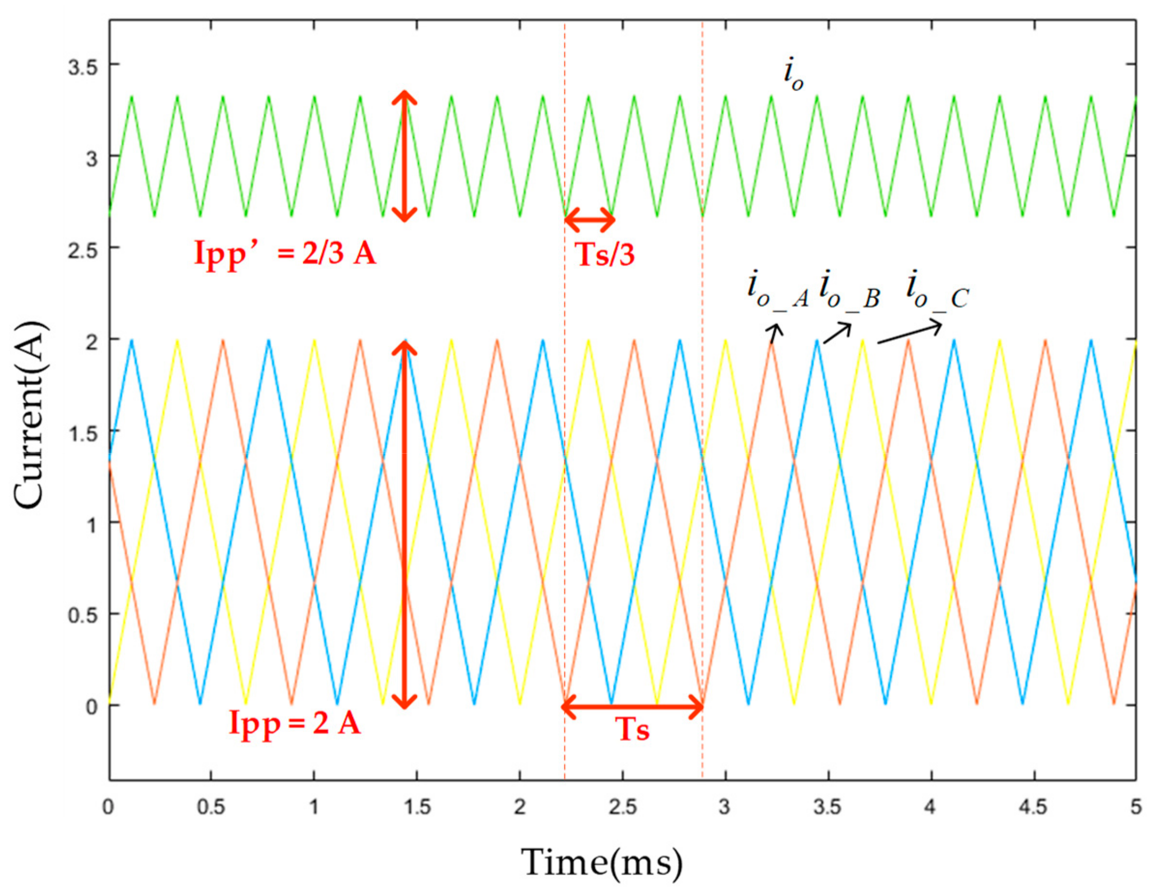
Figure 15b shows the control speed and accuracy of this control strategy. The current ripple is 0.6 A peak-to-peak, which is limited by the inductor and DC side voltage.
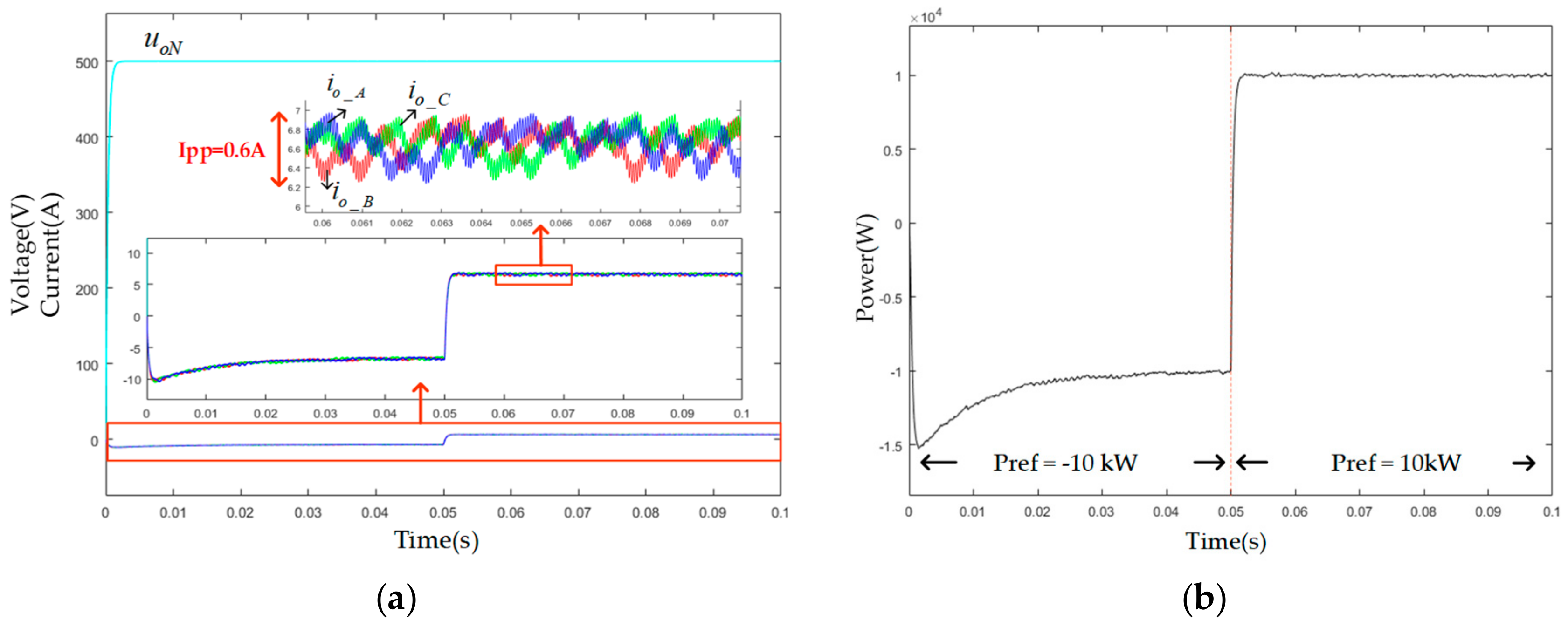
Figure 16 shows the detailed port voltage, current, and power in DC grid mode. During this period, a current step happens at 0.05 s to test the speed of changing power from −1 kW to 1 kW. The power in
Figure 16b shows the control speed and accuracy of this control strategy. The current ripple is 0.6 A peak-to-peak.
Figure 17 shows the detailed port voltage and current during the switch state. Since in the simulation, the switch can be cut off and put in almost immediately, it shows a short and smooth transient state of switching between AC and DC mode.
6. Experimental Verification
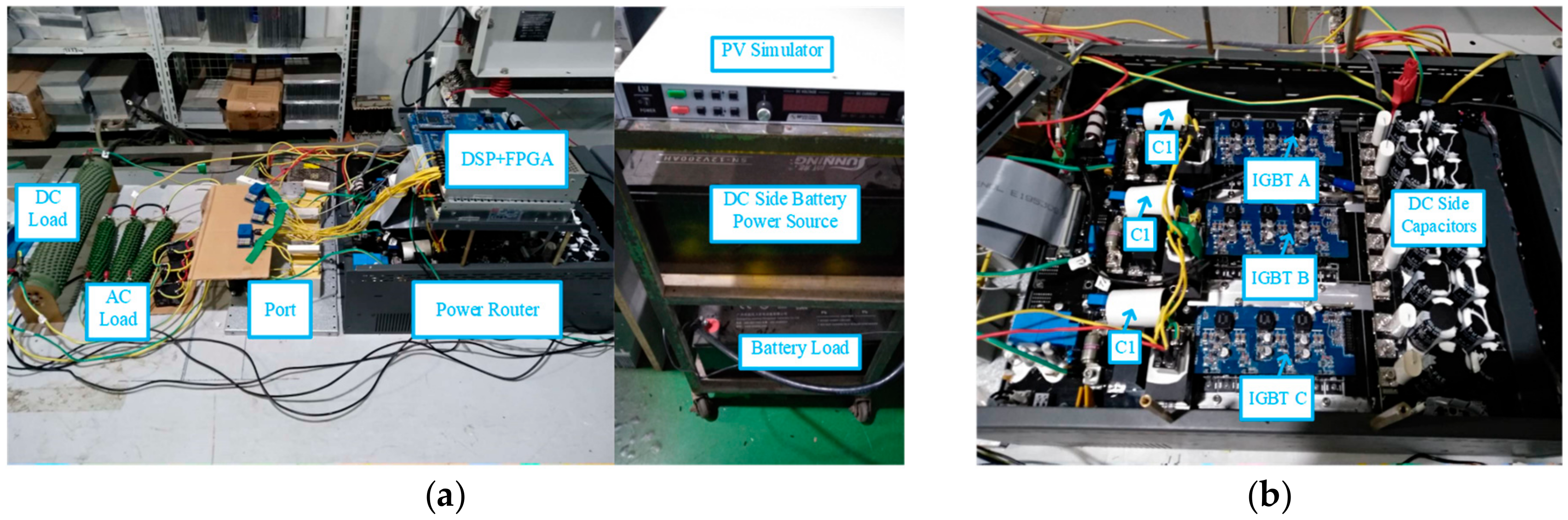
The experimental prototype shown in
Figure 18 was built to verify the proposed power router topology. The prototype consists of a TI TMS320F28335 controller board, a Cyclone EP1C12Q240C8 FPGA and a 3L-NPC converter. The system parameters are the same as those in the simulation except the DC side voltage and load resistance. In the experiment, the DC side voltage is 36 V, DC load is 3 Ω and AC load is 5 Ω each phase. A Programmable DC Power Supply from MAGNA-POWER is used as PV simulator. The DC side battery power source uses three series connected 12 V 200 Ah batteries from SUNNING, while the battery load use one 12 V 200 Ah battery.
Figure 19 and
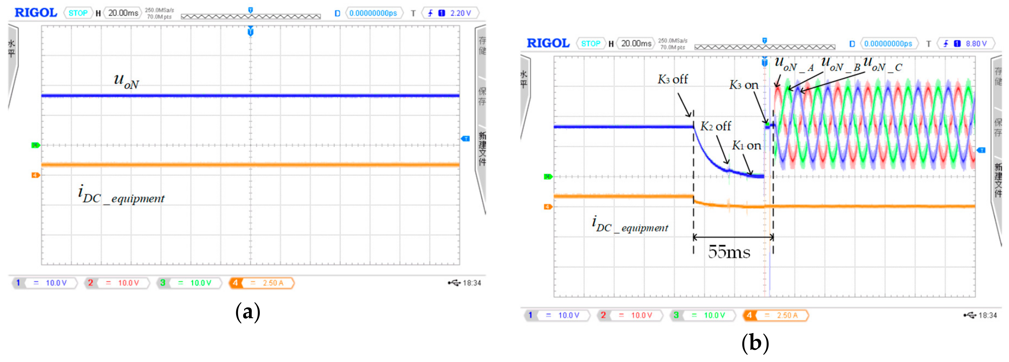
Figure 20 show the experiment results of the power router under switching conditions and steady states respectively. Since power relays are chosen as switches in the experiment, it takes about 25 ms for them to turn on or cut off. Besides, the port voltage is measured as
, which will put a DC bias for the real port voltage in AC mode. The correctness of PR’s operation under AC mode can be seen from the port current.
Figure 19a shows the PR’s port voltage and the current flowed into the load in DC load mode. PS-PWM is adopted, which is the same as that in the simulation. It can be seen that the voltage ripple and current ripple is very small.
Figure 19b shows the PR’s switch from DC load mode to AC load mode. Its switching process is the same as that in
Figure 9. Due to the cut-off and turn on time of the switches, the transient state is easy to observe. When the switch instruction is sent, the switch will not act immediately. Therefore, it takes about 55 ms to change the filter from LC to LCL.
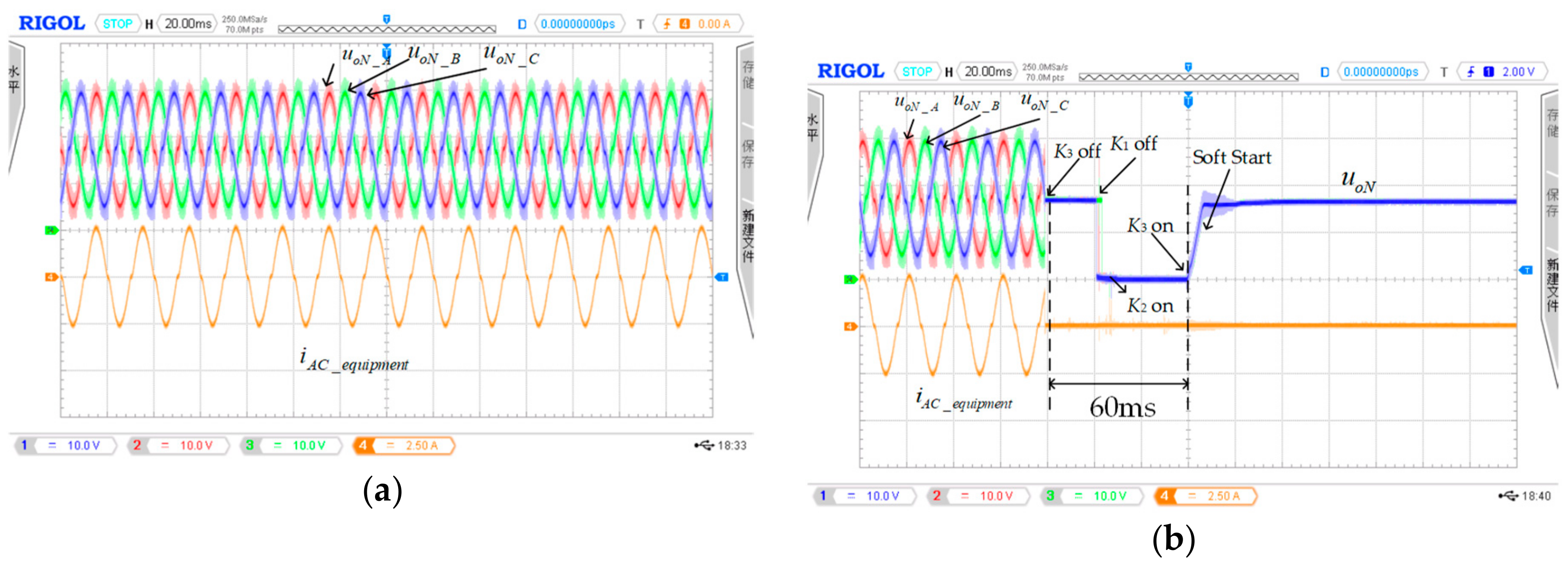
Figure 20a shows the PR’s port voltage and the current flowed into the load in AC load mode. PD-PWM is adopted, which is the same as that in the simulation. It can be seen that the three-phase voltage and current are symmetrical and sinusoidal.
Figure 20b shows the PR’s switch from AC load mode to DC load mode. Its switching process is the same as that in
Figure 9. In this condition, it takes about 60 ms to change the filter from LCL to LC.
The experiment figures also show that the designed transient switch process has a good and safe transient process. From
Figure 19b and
Figure 20b, it can be seen that when the relay
K1 or
K2 is switched on or off, there is only a small spike in the voltage and current. In addition, there is no sign of arcing.
These two modes are used as an example to prove the accessibility of fast switching among different working modes. Due to the use of power relays instead of power electronic switches, the switching time is longer than that in the simulation.
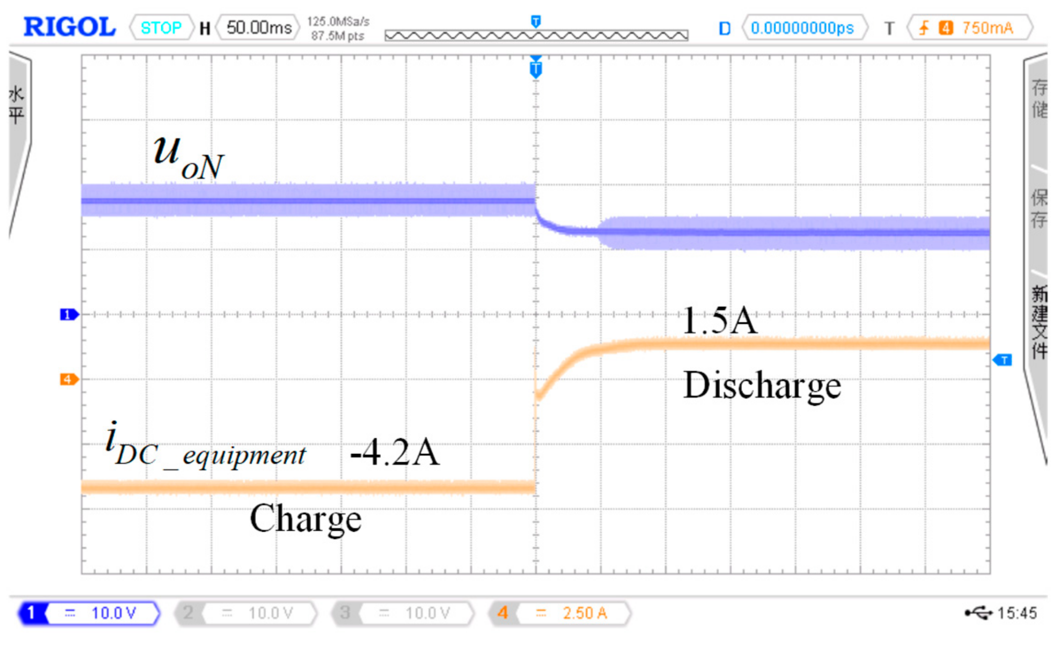
Figure 21 shows the PR’s working ability under battery mode. The port current is controlled from −4.2 A to 1.5 A in 100 ms, which means it changes from the charging state to discharging state. During this state, due to the line impedance, the port voltage drops about 5 V.
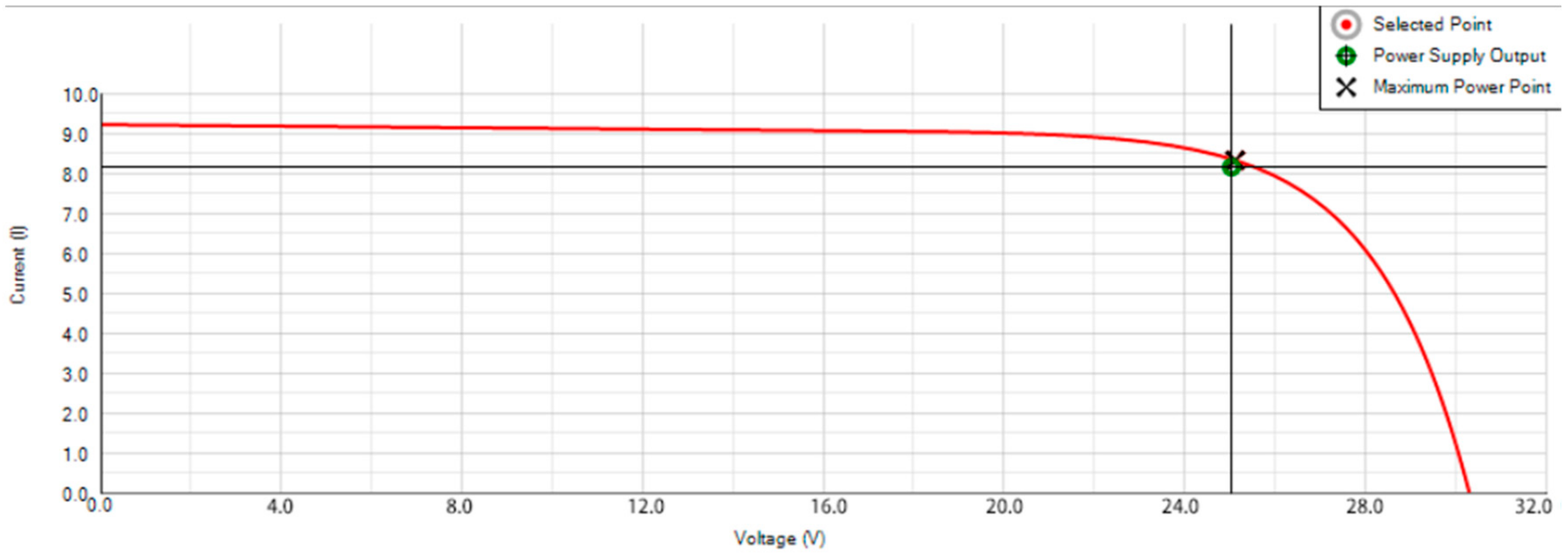
Figure 22 proves the ability of MPPT control of PR under PV mode with high accuracy. This experiment is realized with a programmable dc power supply from MAGNA-POWER. The user interface shows the power supply output and the maximum power point of the power supply. From
Figure 22, it can be seen that the actual working point is close to the pre-set maximum power point. Therefore, the power router has the ability of MPPT control.


