Article

Improvements of the Starting Performance of A Novel Brushless Doubly-fed Motor Based on the Composite Coils

College of Electrical & Automatic Engineering, Hefei University of Technology, Hefei 230009, Anhui, China
*
Author to whom correspondence should be addressed.
Energies 2019, 12(6), 1157; https://doi.org/10.3390/en12061157
Submission received: 18 February 2019 / Revised: 15 March 2019 / Accepted: 21 March 2019 / Published: 25 March 2019

Abstract

:
Brushless doubly-fed motor (BDFM) has well applicable potentials in the speed control driving field due to its excellent speed regulation performance. However, the poor starting performance becomes a shortage that still limits the development and application of wound BDFM. To solve the problem, this paper presents a novel BDFM adopted rotor winding based on the principle of the composite coil. Both the principle of the composite coil and the designed example of the rotor winding are analyzed in detail in this content, and the stator winding designed by the change-pole method is described. The performance of the prototype was tested by simulation and experiments, both results reveal that this method can effectively improve the starting performance of BDFM, the system is simplified, and the stability of it is prompted.

1. Introduction

Brushless doubly-fed motor (BDFM) is a new type of AC motor. It consists of two sets of stator winding which are power winding (PW) and control winding (CW), and a set of the rotor with special structure [1,2]. By altering PW and CW into different pole pairs, the two sets of stator winding modulate the rotating magnetic field of stator through the coupling with rotor magnetic field, which achieved the electromechanical energy conversion [2,3,4,5,6,7,8]. The rotor structure could be a nested-loop cage, reluctance or wound rotor [5,6]. The rotor plays the role of “pole pairs converter” in the operation of the BDFM, and its structure and property have an influence on the power density and efficiency of the motor [5,9].
For the wound rotor BDFM [5,10], the most significant advantage is that the number of turns and pitch of the rotor winding can be changed flexibly [1,5,11]. Therefore, the harmonics can be reduced effectively, and the winding coefficient of the two main magnetic fields can be increased markedly. However, the starting performance of the motor is not as good as that of the nest-loop cage rotor BDFM. The excessive starting current will cause the fluctuation of the grid voltage (especially when the large capacity motor starting up) during the starting process, which affect the normal operation of other equipment connected to the power network. Besides, it can make the winding of the motor heating and accelerate the insulation aging, which shortens the service life of the motor, especially for those starting frequently [12]. Therefore, it is crucial to improving the starting performance of the wound rotor BDF motor.
In the starting process of a conventional wound asynchronous motor, we usually change the rotor resistance to improve the starting performance. During the calculation, the parameters of the rotor side are usually converted to the stator side, and the converted values of parameters are distinguished by the superscript “ ”. The commutation equation is given as:
R 2 = m s m r ( N s N r ) 2 R 2
where R 2 and R 2 are separately the actual and converted values of the rotor resistance; m s and m r are stator and rotor phase number; N s and N r are effective turns per phase of stator and rotor, respectively.
The increasing actual rotor resistance causes the larger value of R 2 ; thus the starting current of the motor is suppressed. At the same time, the starting torque is increased accordingly, and we can see the process by observing the T-s curve [13,14,15,16], as shown in Figure 1.
It can be seen from Figure 1 that the curve shifts to the left and keeps the maximum value of the torque constant when the rotor resistance value increases. However, the stability of the system is reduced because an external resistance is required. The principle of this method is to increase R 2 by enlarging the value of R 2 , in order to restrain the starting current and increase the starting torque. The emphasis of our research focuses on increasing the value of R 2 without changing the true rotor resistance to achieve a similar starting effect. So, we tried to reduce the value of N r to achieve the goal.
This paper proposes a novel BDF motor [17,18] with rotor winding designed based on the principle of “composite coils”. In the starting condition, N r , the effective coil-turns of each phase winding of the rotor reduces due to the counteracting action of the “composite coils”. After the end of the starting process, effective coil-turns of each phase winding returns back to normal during the running condition, the rotor resistance conversion value is normal, and the motor operates with lower loss. The stator winding designed by the change-poles method is used to switch the starting conditions to the working conditions. The effect of the structure on the starting characteristics is verified by the simulations and the prototype experiments.

2. The Principle of Composite Coils

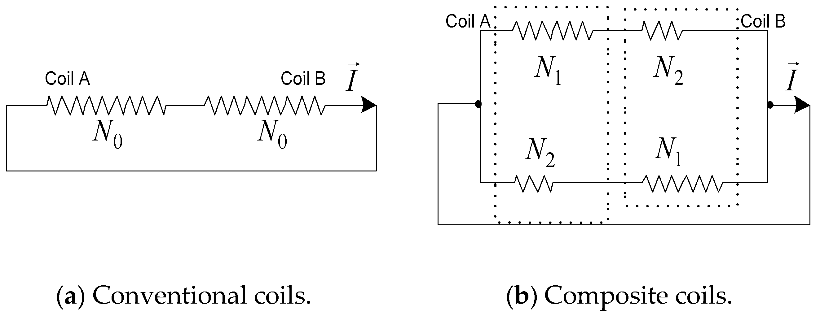
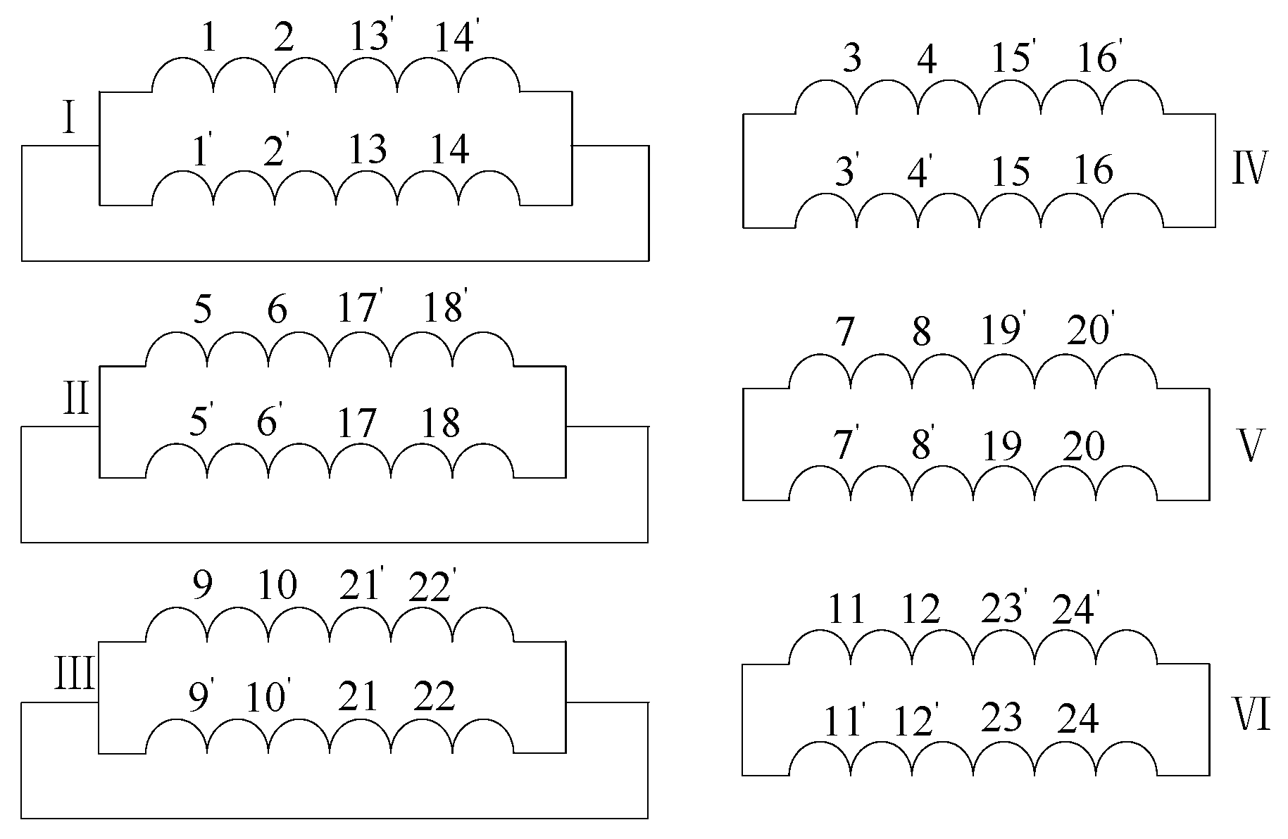
2.1. The Structure of Composite Coils

It is assumed that a part of the rotor winding is constituted by two sections of coils (coil A and coil B), which do not have interaction affected by the phase of (Electro Motive Force) EMF. The number of turns in each coil is N 0 . This part of coils from A and B are now divided into two parts, including multi-turns coils ( N 1 turns) and minor-turns coils ( N 2 turns) ( N 1 > N 2 , N 1 + N 2 = N 0 ). The two set of coils form a composite coil group through a parallel connection, and the equivalent circuit is shown in Figure 2.

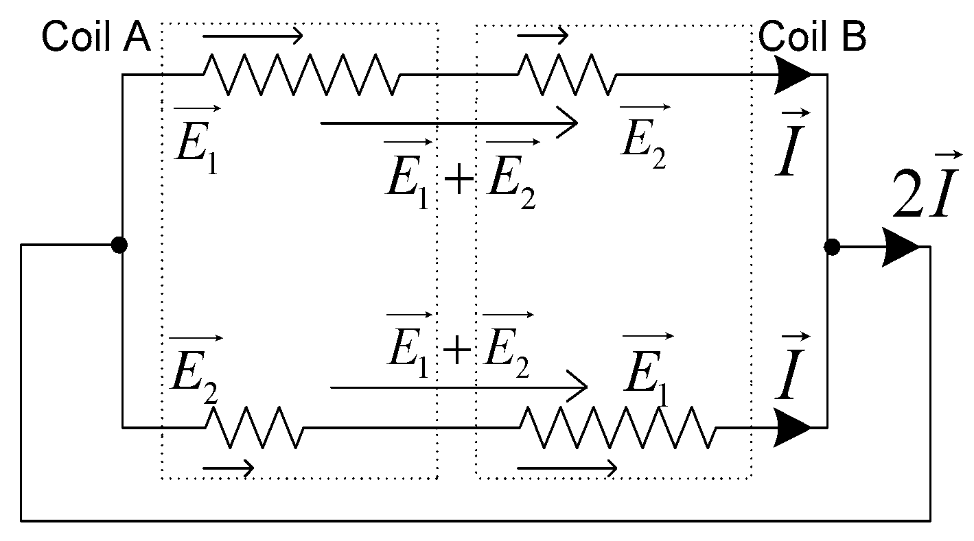
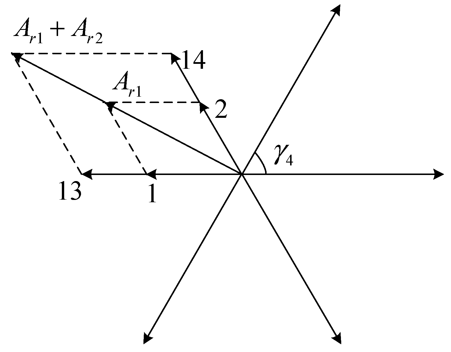
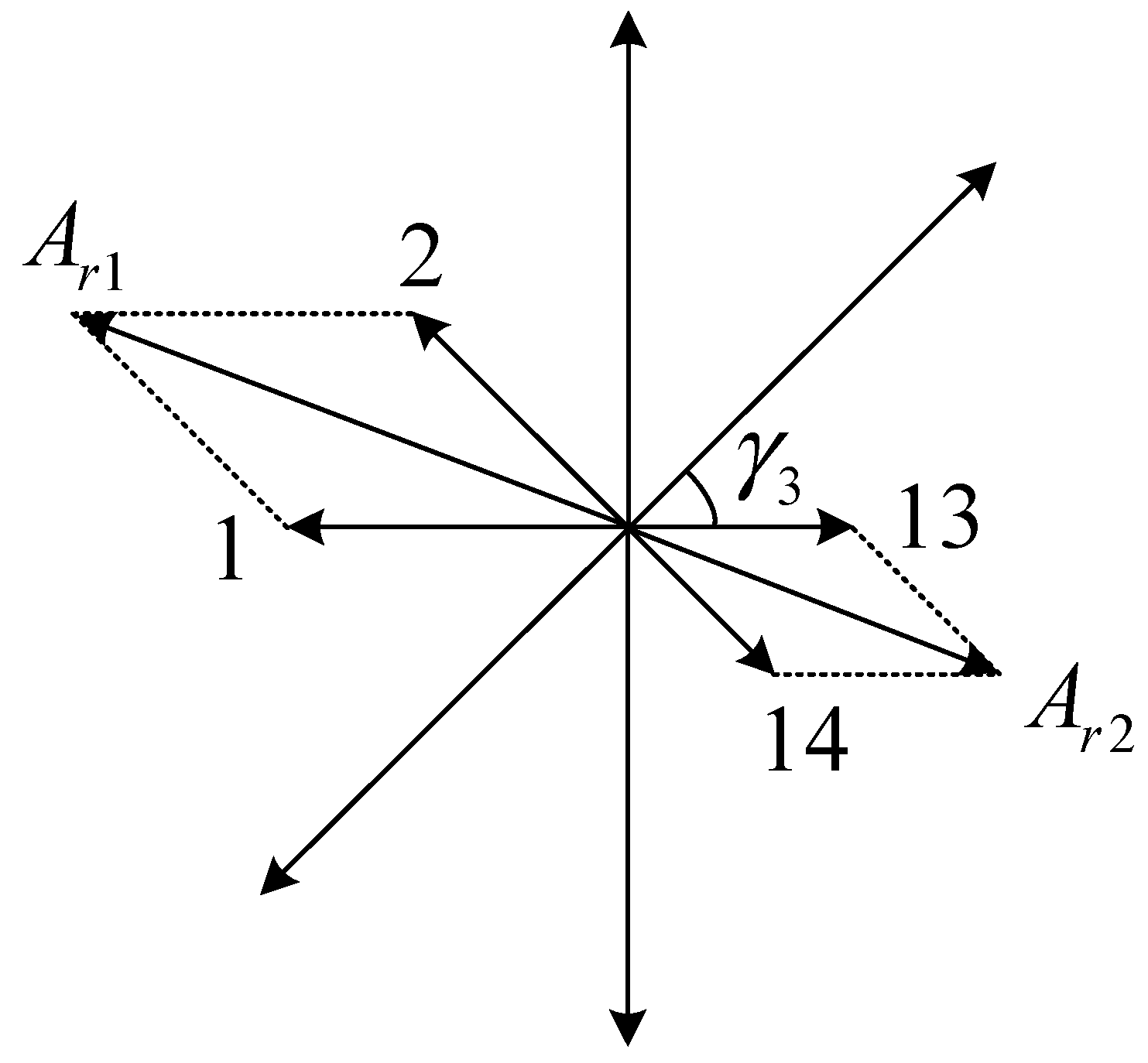
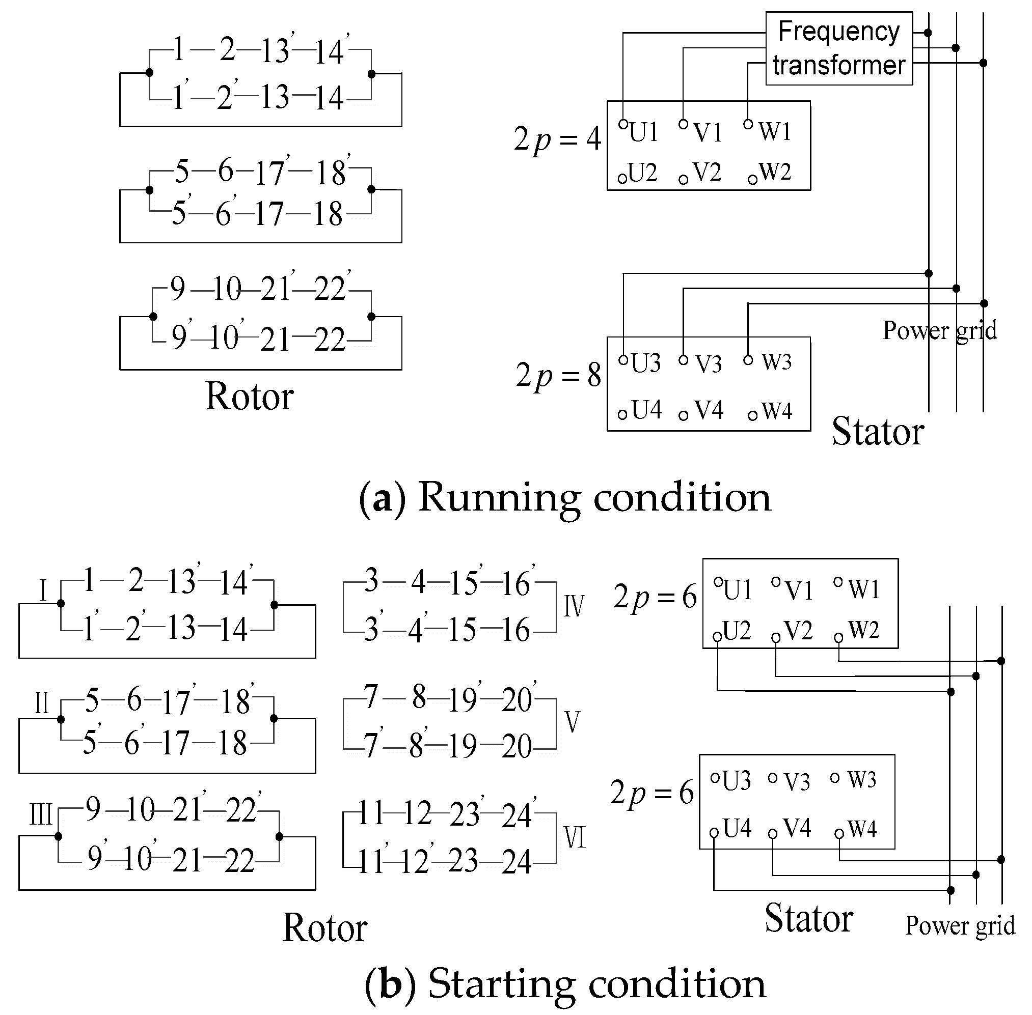
2.2. The Running Condition of Composite Coils

According to the phase relationship between the composite coil A and B, the composite coil group has two different working conditions. Regarding the phase of the composite coil A as the reference, when the phase of composite coil B is the same with A, the motor is in the running condition, which is shown in Figure 3. The synthetic EMF of the two branches is equal and in the same direction, with the value E 1 + E 2 . According to Kirchhoff’s current law, there is no current loop inside the coil group, while the group forms a closed loop with the external connection. Meanwhile, the number of effective turns per phase remains N 1 + N 2 constantly.
Therefore, according to Equation (1), the converted values of the rotor resistance at the runtime is:
R 2 r u n = m s m r ( N s N 1 + N 2 ) 2 R 2
It can be seen from Equation (2) that the converted values of the rotor resistance do not change at this time. That is to say that when the phases of the two coils are the same, the effective turns of each phase of the rotor winding maintain a normal value and the converted values of the rotor resistance remain normal. At this time, the motor is in an operating state. It can also be stated that the composite coil does not increase the running loss of the motor during operation and the motor maintains efficient operation. The operating state is that the motor switches to synchronous, asynchronous or doubly-fed operation after reaching the natural synchronous speed.

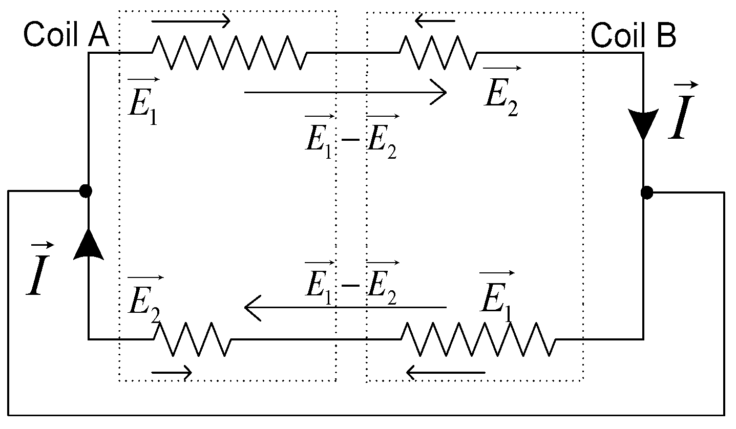
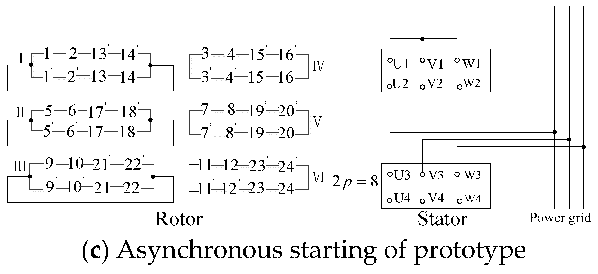
2.3. The Starting Condition of Composite Coils

During the starting, the phase of the composite coil B is opposite to A, as shown in Figure 4. The synthetic EMF of the two branches, respectively, have a decline to E 1 E 2 and in the opposite direction. At this time, the currents generated in the two branches are equal in magnitude and opposite in direction. According to Kirchhoff’s current law, there is no current in the external wiring. So, the inducted current only forms the circulation inside the composite coil group. As a result, the number of effective turns is reduced to N 1 N 2 .
Therefore, according to Equation (1), the converted values of the rotor resistance at the time of starting is:
R 2 s t = m s m r ( N s N 1 N 2 ) 2 R 2
It can be seen from Equation (3) that the number of effective turns per phase of the rotor winding is reduced to N 1 N 2 , and R 2 s t is inversely proportional to ( N 1 N 2 ) 2 . So, the value of R 2 s t is significantly increased. That is to say that when the phases of the two coils are opposite, the effective number of turns per phase of the rotor winding is reduced and the rotor resistance conversion value is significantly increased. At this time, the motor is in the starting state. The starting state refers to the transition phase of the motor speed rising from zero to the natural synchronous speed.
Therefore, the relationship between the rotor resistance conversion value and the rotor resistance conversion value during starting and running is given as follows:
R 2 s t = ( N 1 + N 2 N 1 N 2 ) 2 R 2 r u n
It can be seen above that the conversion value of the rotor resistance during the starting process is far more than that of operation.
It is known that the actual value of the rotor leakage reactance per phase is proportional to the square of the magnetic motive force (MMF) producing it. When the motor is in running condition, the actual value of leakage reactance per phase is directly proportional to ( N 1 + N 2 ) 2 , while the value is proportional to ( N 1 N 2 ) 2 during starting.
X 2 s t = X 2 r u n ( N 1 N 2 N 1 + N 2 ) 2
In Equation (5), X 2 s t and X 2 r u n are separately the actual values of rotor slot leakage inductance per phase during starting and running process.
It is known that the conversion coefficient K of rotor leakage inductance, which is relative to the stator side, is proportional to the square of the effective turn number of the coil producing the leakage reactance. The number of effective turns during running condition is N 1 + N 2 , and the effective turn number in the starting process is N 1 N 2 . The relation between the conversion coefficients of two conditions, K 2 r u n and K 2 s t , is given as follows:
K 2 s t = K 2 r u n ( N 1 + N 2 N 1 N 2 ) 2
Known from Equations (5) and (6):
X 2 s t = K 2 s t X 2 s t = X 2 r u n
where X 2 r u n and X 2 s t are the converted values relative to leakage reactance per phase when the rotor winding is in the running and starting process. It can be seen that the converted value of leakage reactance per phase remains unchanged in different conditions.
It can be seen from Equations (4) and (7) that when the composite coil is adopted, the conversion value of the resistance R 2 s t increases substantially according to the square of the ratio with effective turns during the starting process, but the value of rotor leakage reactance per phase remains unchanged. Under these conditions, the starting torque will increase. In addition, with the increase in rotor resistance, the starting current reduces. As a result, the starting characteristics are improved significantly with the increase in the starting torque and the reduction in the starting current.
A problem can be raised from statements above, that how to change the phase of the two coils in a composite coil group while the winding connection does not change, in order to make the composite coil works in different states. This is described in detail in the following sections in conjunction with the design examples.

3. Winding Design Example

3.1. Rotor Winding Design

The working conditions of the prototype are described in detail below. Test prototype is a BDFM with the pole pairs of two and four, in which the stator slot number is 36, and the rotor slot number is 24. The turns of the multi-turns part and the minor-turn part in the composite coil are separately N 1 = 12 and N 2 = 6 . The pitch of the rotor winding is y r = 3 .
The theory of composite coils is further explained by the design examples below. The connection of rotor winding is shown in Figure 5. The minor-turns coils are marked by “ ”, and the rest is the multi-turns part.
As shown in Figure 5, the rotor winding consists of six sets of composite coil groups. Among them, the wiring mode of the group I , II , and III is the same, while IV , V , and VI cancel the external connection line.
The design of the prototype divides the working states into two conditions, starting and running conditions. For running condition, the prototype can be regarded as a conventional 4/8 BDF motor, and the phases of the two sets of coils in the composite coil are required consistently. Taking I as an example, the phases of slot 1 and 2 are the same as those of 13 and 14, which means the phases of composite coil A and B are the same. In the starting condition, the pole pair numbers of the two sets of stator winding are both three. Meanwhile, the phases of slot 1 and 2 are completely opposite to those of 13 and 14, which indicates that the phases of composite coils A and B are opposite. The theory above is further explained in combination with the slot vector diagram.
For the certain pole-pairs magnetic field, there is a skewing between two vectors in adjacent slots that can be expressed as γ p = 2 π p / Z r , where p is the pole pairs, Z r is the sum of rotor slots, equal to 24. All the slot-vectors are marked with slot numbers and are distributed along the circumference to form a star pattern. The pattern is named as slot electrical potential star Vectogram. The synthetic of the slot-vectors which contained winding in each phase can be equivalent to the general MMF, also called synthetic MMF. The slot electrical potential star Vectogram determines the magnitude and direction of all the MMFs.
In the running state, the main magnetic fields induced by the rotor winding are eight poles and four poles. Taking I as an example, when p = 4 , γ 4 = π / 3 . The slot electrical potential star Vectogram is shown in Figure 6.
It can be seen from Figure 6 that the synthetic MMF of the slot 1 and 2 separately have the same rotational direction with that of slot 13 and 14. Therefore, in the running state, each of the two parallel branches of each composite coil group generates induced electromotive forces in the same direction, as shown in Figure 3 for groups I , II , and III , and the interior-induced current forms a loop via the external wiring. However, for groups IV , V , and VI , the electromotive forces of upper and lower branches cancel each other out without the external wiring. Hence IV , V , and VI do not generate electromotive forces in the same direction when the motor is running normally. When p = 2, the analysis of this process has the same conclusion.
In the starting condition, p = 3 and γ 3 = π / 4 . The corresponding slot electrical potential star Vectogram is shown in Figure 7.
As shown in the Figure, the direction of the slot-vector 2 is opposite to the direction of 14; since the direction of 1 is opposite to 13. Therefore, the two synthetic MMFs, A r 1 and A r 2 , are opposite. Hence in the starting state, the EMF synthesized by the two branches, respectively, has a decline to E 1 E 2 . The number of effective coil turns per phase rotor winding is thereby reduced, and an induced current is generated inside the parallel branches, as shown in Figure 4. No current flows through the external wiring of groups I , II , and III .
In summary, different pole-pairs magnetic fields cause the composite coil running in different operating states. The stator winding designed by the pole-changing method meet the design requirements.

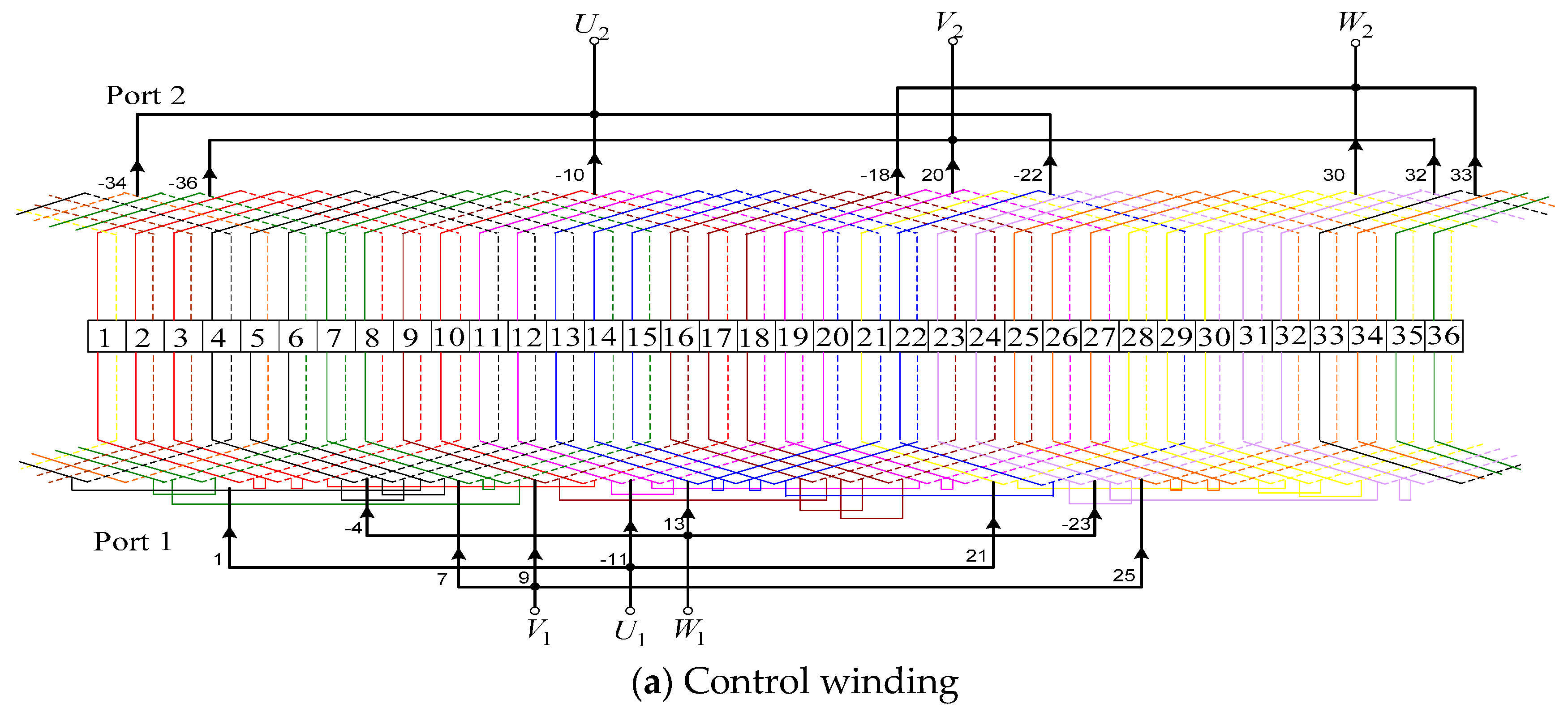
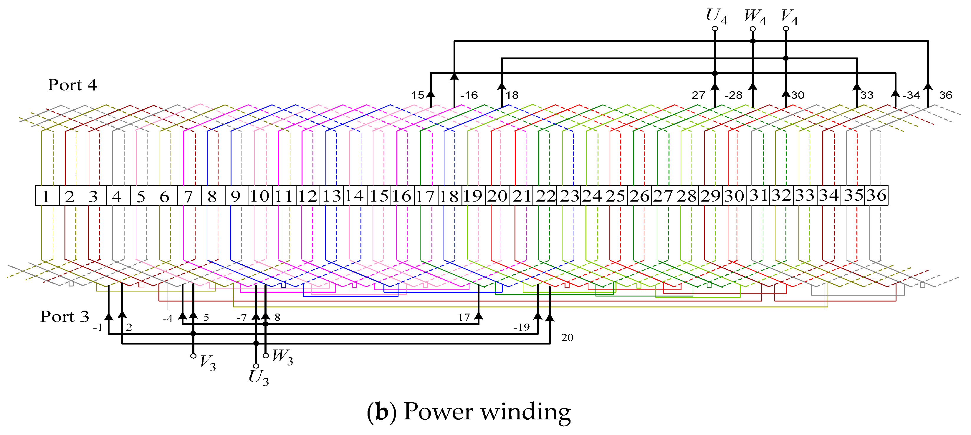
3.2. Stator Winding Design

The design purpose of the stator winding is to switch the working conditions of the motor and generate the corresponding magnetic fields for different pole pairs. Stator winding slot number is Z s = 36 . The stator winding is divided into two sets, PW and CW, while the pitch is y c = 7 and y p = 5 . The connection diagram of the stator winding is shown in Figure 8.
As shown in Figure 8, Port 1 and 3 correspond to four poles and eight poles, respectively, while port 2 and port 4 are both the six poles mode. The connection methods of the rotor winding in different working conditions are shown in Figure 9. The connection diagram of the rotor winding is shown on the left, and the right side is the stator winding.
The prototype operates normally as a BDFM, with the port connection diagram shown in Figure 9a. The inductive EMF of the upper and lower branches counteracts each other, so no current is drawn inside the composite coil. In particular, port 2 and port 4 are blanked, and port 3 is directly connected to the power grid, while port 1 is connected to the power grid through frequency converter. When the prototype starts, port 2 and port 4 are connected to the power grid, and the other two ports are blanked. Figure 9b shows the port connection mode in detail. When the motor speed is stable, the prototype can turn to doubly-fed operation by using switches. In addition, normal BDFM can start with the asynchronous mode. The port connection is illustrated as follows: port 3 is connected to the power grid, and port 1 shorts out. The rest of the ports are blanked. Figure 9c shows the connection in detail.
When the motor starts, it can be seen as an asynchronous motor with the pole pairs number as 3. Figure 7 shows that the phases of slot 1 and 2 are opposite to those of slot 13 and 14; in other words, the phases of composite coils A and B in Figure 8 are opposite. According to the principle of the composite coils, the inductive EMF synthesized by the two branches gets smaller, and they are equal in size but opposite in phase. There are current loops forming inside the parallel branch of the coil group. The effective number of turns in the rotor slot is reduced, while the rotor resistance is multiplied. Hence, the starting current reduces and starting torque increases with the improvement in the referred value of the rotor resistance.
When the motor speed rises to 500 rpm, the motor can be transferred to the running state and achieves the speed regulation. During operation, the motor works as a BDFM with pole pairs 2 and 4. The phases of slots 1 and 2 are the same as those of slots 13 and 14, which means the phases of composite coils A and B are same. The analysis shows that the EMF of three parallel branches in Figure 9a is equivalent in size and has the same direction. The function of IV , V , and VI can be ignored in the operation state, and thus they are not displayed in the Figure. For the rotor, it is demonstrated that the effective number of turns per phase does not change, and the rotor is in a low-resistance state relative to the stator.
The conclusion is that the composite coil only acts in the starting state, leading to an increase in the referred value of rotor resistance. In the operating state, the constant value does not cause extra loss.
Figure 10 is the port wiring diagram of the prototype when it is overall running. When the motor starts, the switch K 1 is closed and switch K 2 is opened. This is the starting state shown in Figure 9b. After the process of starting is completed, the switch K 2 is closed and switch K 1 is opened. This is the operating state shown in Figure 9a. In this state, the prototype can complete the speed adjustment task. The switching of the two sets of three-phase switches can be controlled by the signal generated by the speed sensor. In daily tests, manual switching can also be performed directly after the speed has reached the required level.

4. Simulation and Experimental Research

To verify the validity of the method proposed in this paper, the experimental prototype is made with motor YZR132 as a reference, and the experimental platform is shown in Figure 11. The pole pairs of CW and PW are separately two and four; both of them are short distance winding with three-phase symmetrical double-layer regular 60° phase. The rated power of prototype is 4 kW; the rated voltage and current are 380 V and 7 A, respectively; the grid frequency is 50 Hz.
The coils of CW and PW are placed in the slot bottom and opening layers of the stator winding, respectively. In Figure 5, the upper branch of the parallel circuit is placed in the over layer of the rotor winding, while the lower branch is put in the layer beneath. The specific parameters of the prototype are shown in Table 1.
The test platform of the prototype is shown in Figure 11. The dynamometer is coaxially connected to the prototype, and its function is to apply different load torques to the prototype to measure the starting performance when different load torques are applied to the prototype. In order to prevent the grid impact and the destruction of prototype resulting from the large starting current generated during the load test, a voltage regulator is used for adjusting the voltage gently with the help of the multimeter. Hence, only the steady-state waveform is attained during the load test. The function of the current clamp is to measure the current present in each wire. The oscilloscope displays the current measured by the current clamp. In this way, the current waveform of the prototype under different load conditions can be obtained.

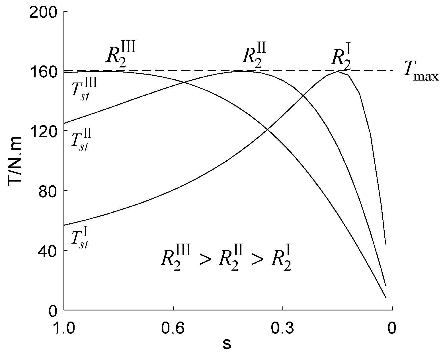
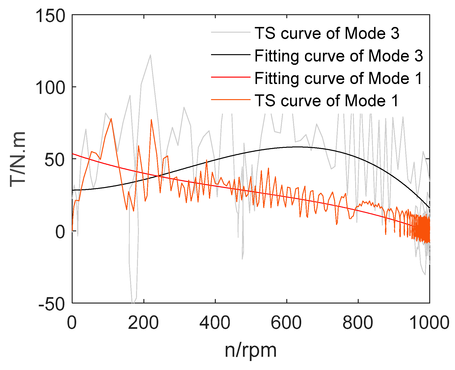
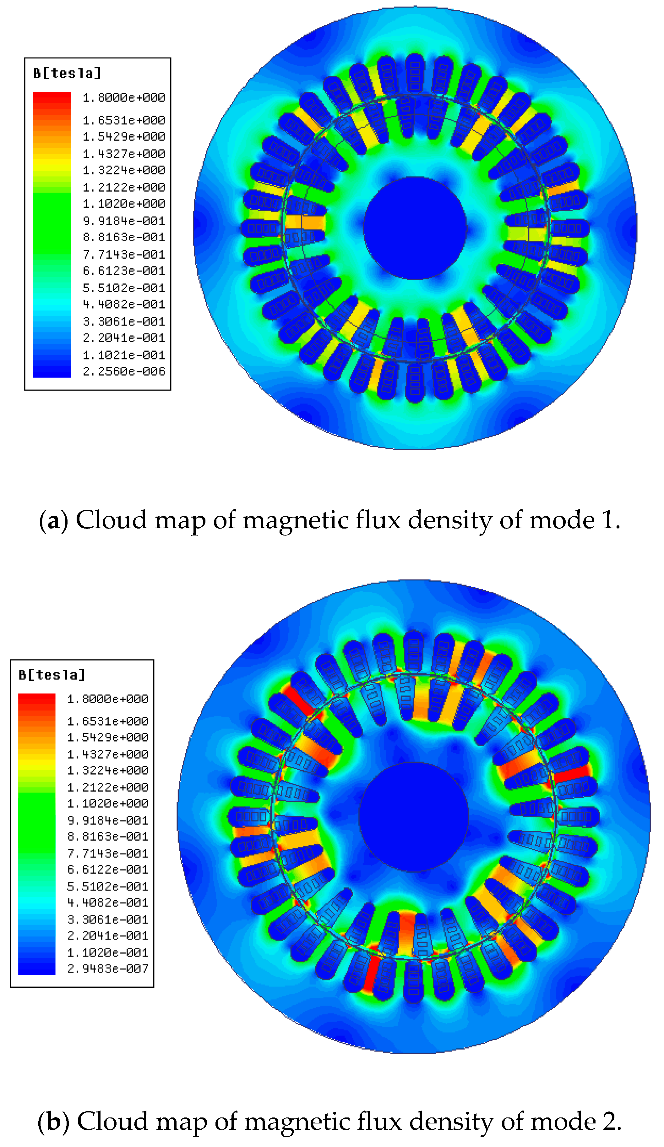
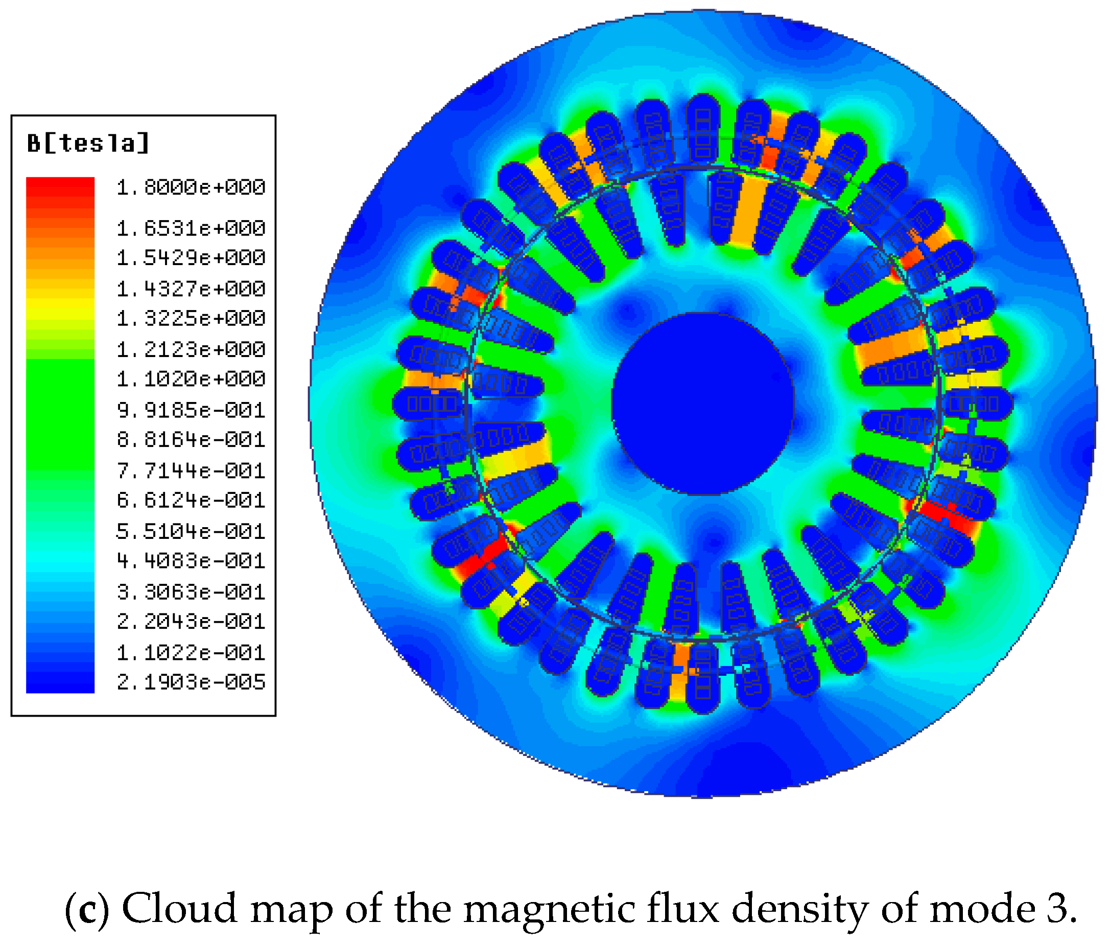
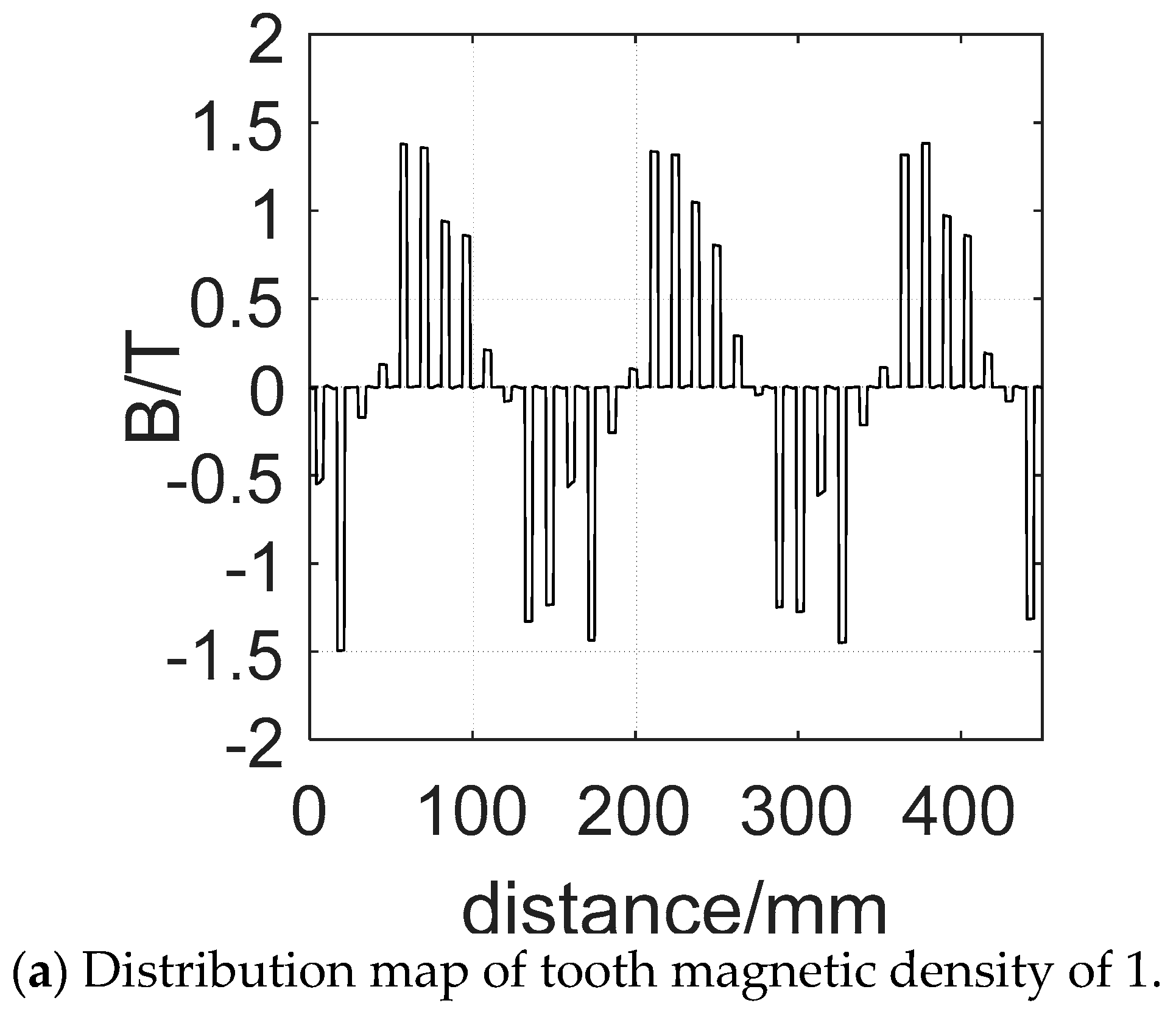
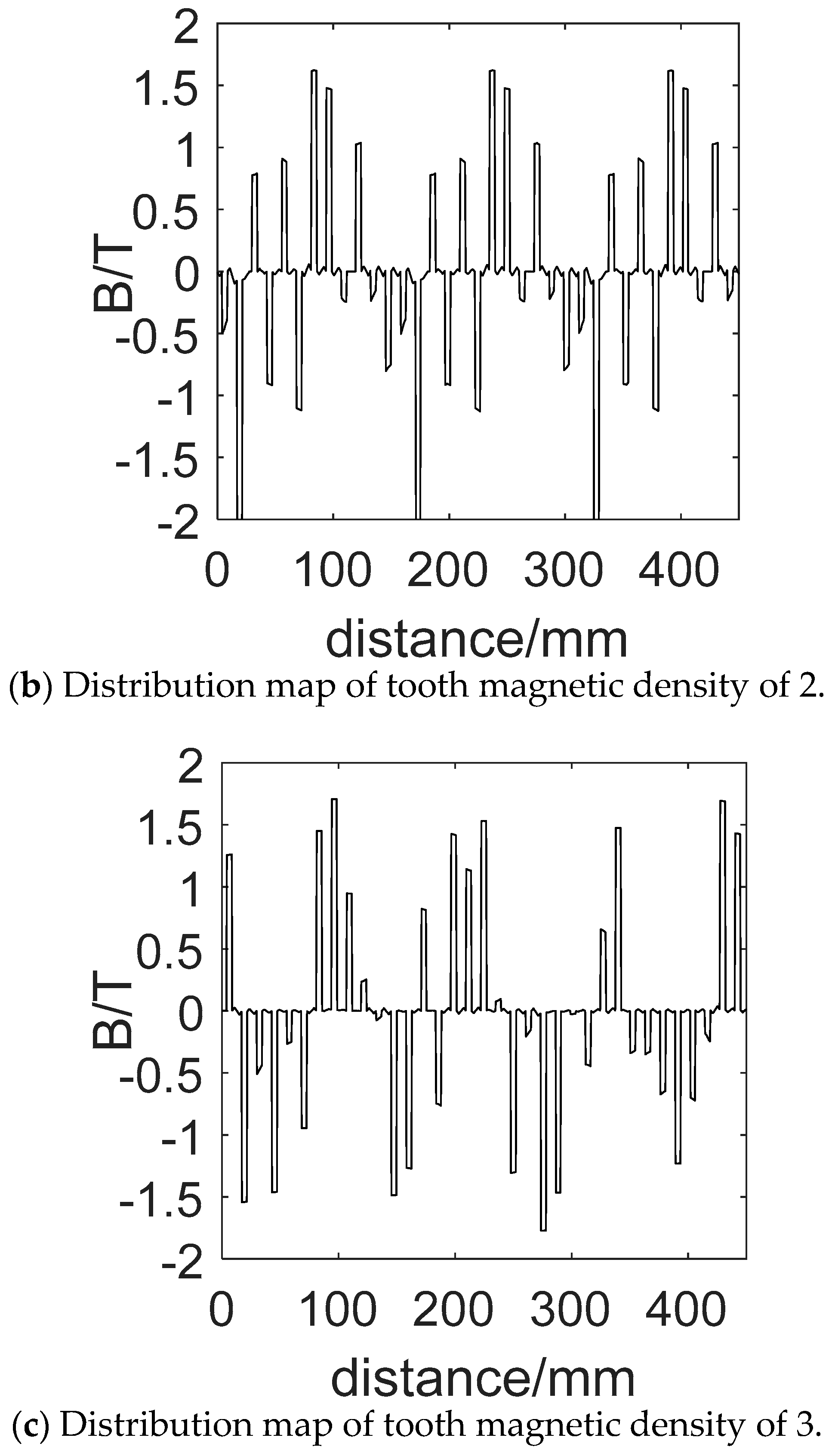
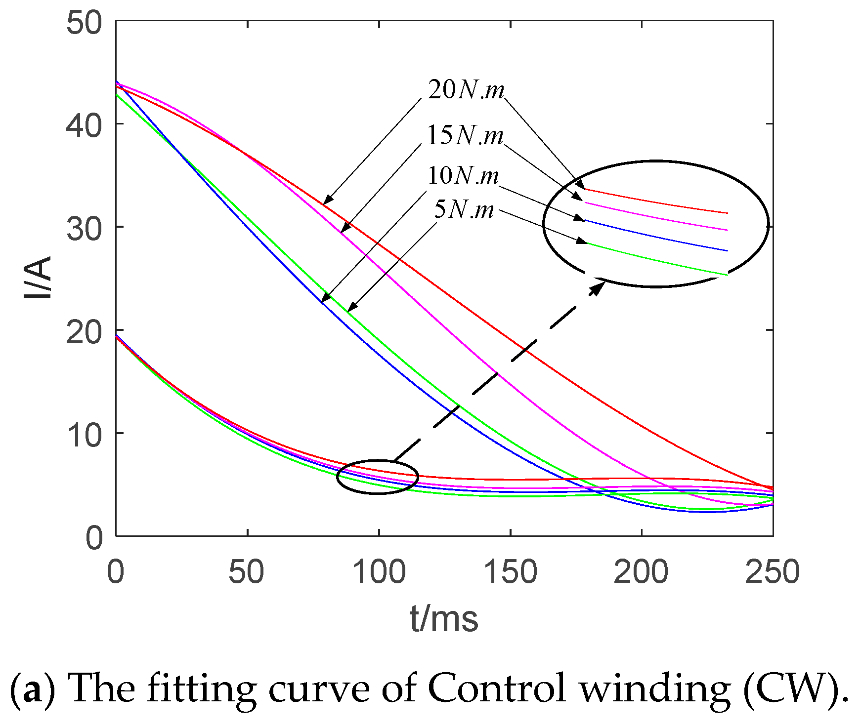
4.1. Effect of Composite Coil Set on Starting Torque

It is mentioned in Section 2 that the rotor resistance increases multiplied under the starting condition. This phenomenon is verified by observing the change of the T-s curve. After the calculation of the parameter, the motor model with rotor structures of both common coil and composite coil group are simulated in Matlab (R2015b, MathWorks, Natick, MA, USA). In order to ensure the accuracy of the simulation results, the length of the iron core and other parameters of the two models, such as the materials used, are the same. The torque-speed curve is shown in Figure 12.
In Figure 12, Torque 1 is the torque-speed curve of the motor model with the rotor using composite coils, while Torque 2 is for the rotor with a common coil. With the comparison of two curves, it can be seen from Figure 12 that for the rotor using composite coil group, the converted value of rotor resistance increases and the starting torque rises up. Then, two different motor models are established in the same way by finite element analysis, and the no-load simulation is carried out. The only difference between the two models is whether the composite coil is adopted. The fitting curve of transient torque-speed is shown in Figure 13.
It is found in Figure 13 that the torque instantaneous value of the motor with the common coil fluctuates greatly, which makes the speed to fluctuate greatly and causes poor stability when the motor reaches the natural synchronous speed point. By contrast, the torque fluctuation of a motor designed with composite coil group is small, which makes the motor stable near the natural synchronous speed point. The trends of torque-speed curves in Figure 12 and Figure 13 are roughly the same. However, the values of the points of the two curves in Figure 13 are small. This may be because the finite element software uses the magnetic field as the analysis object in the analysis, while in Matlab, the numerical calculation is performed according to the mathematical model formula. Therefore, there are subtle errors in the two simulation results.
The above simulation and analysis results show that the rotor winding structure using composite coil group under the starting condition can improve the conversion value of (rotor) resistance of rotor winding and the starting torque of the motor. Although the practical starting torque measurement is limited by the laboratory funds and equipment, the simulation results of both software reveal that the composite coil increases the starting torque. The following verification of the effect of the composite coil on the starting current will be carried out.

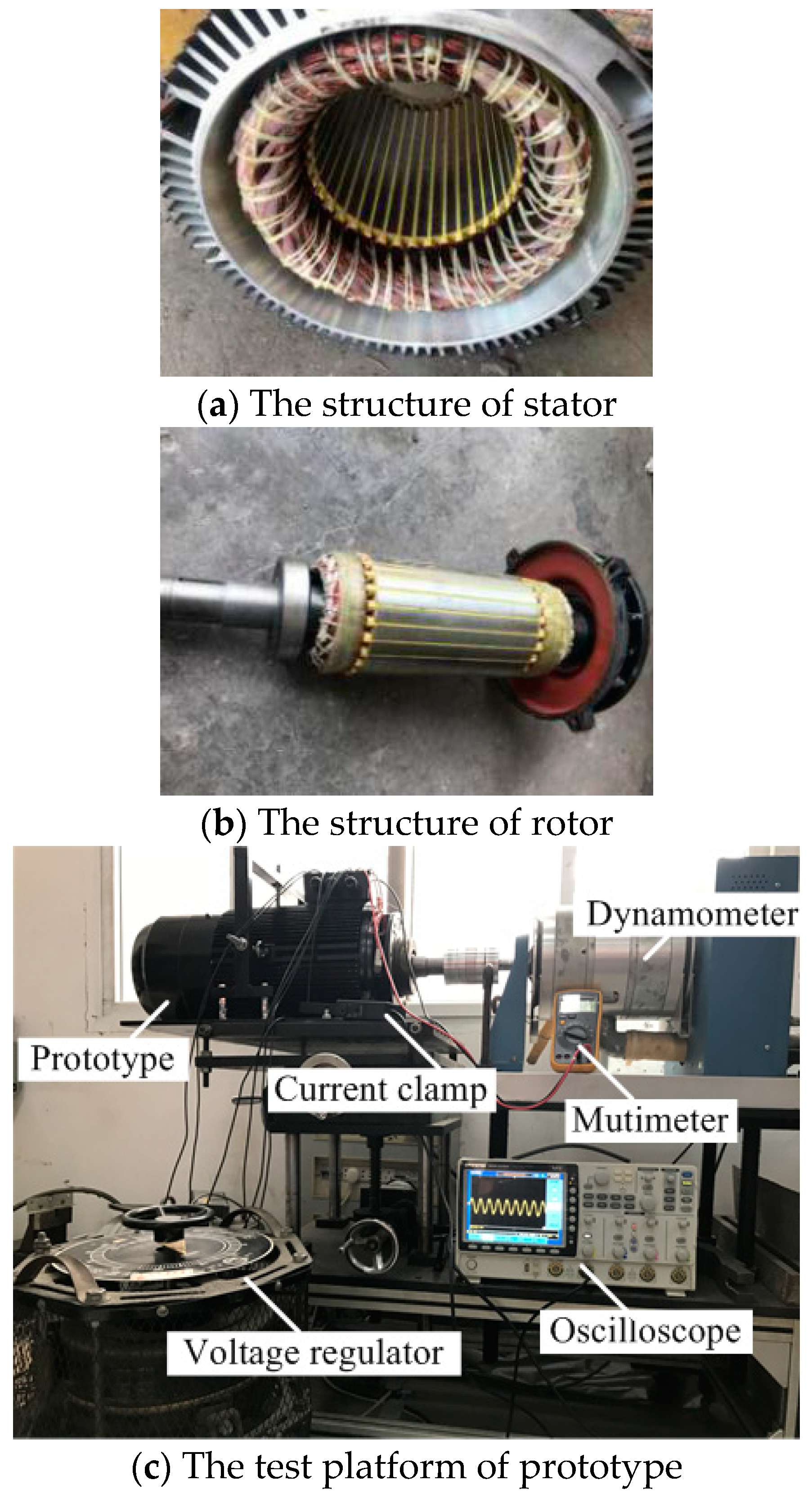
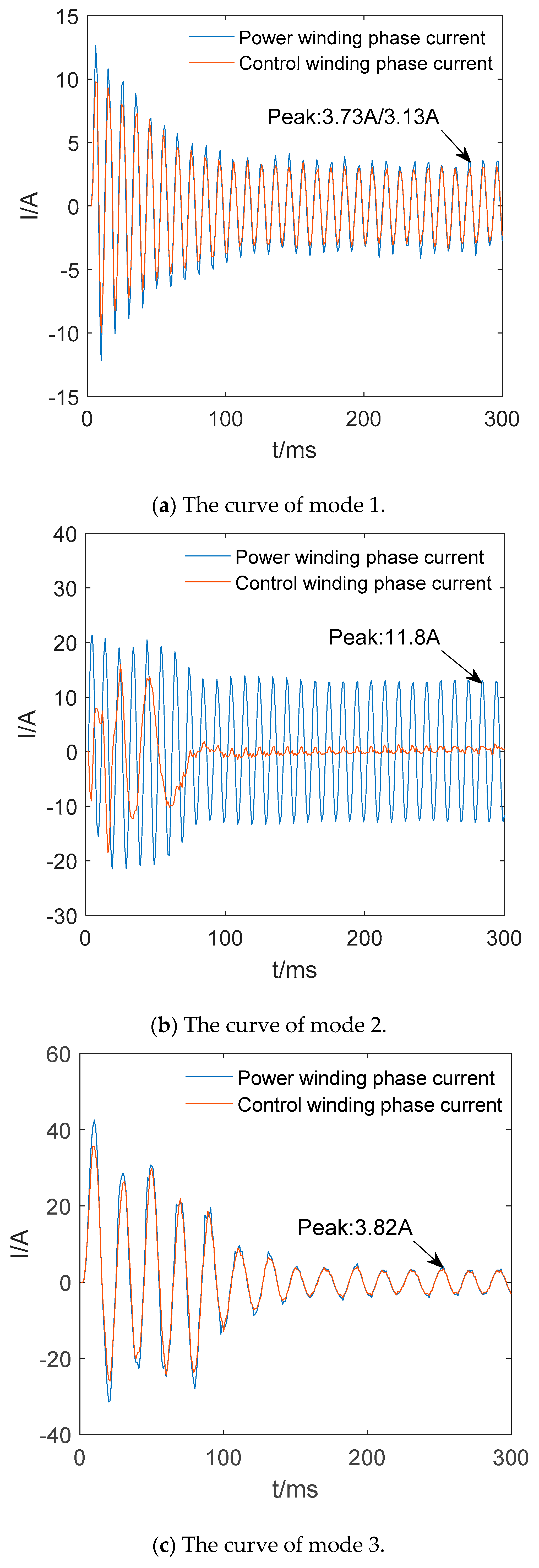
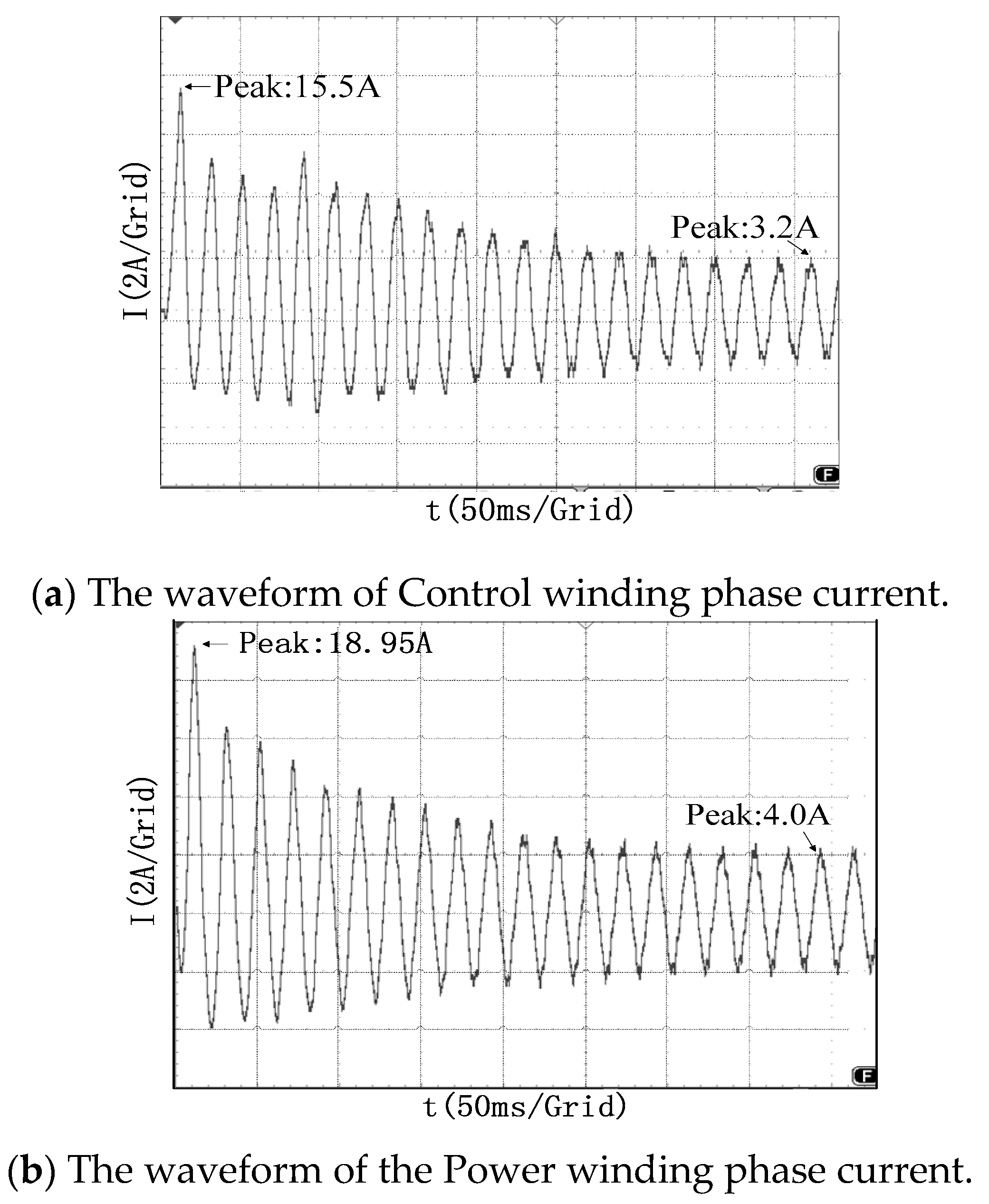
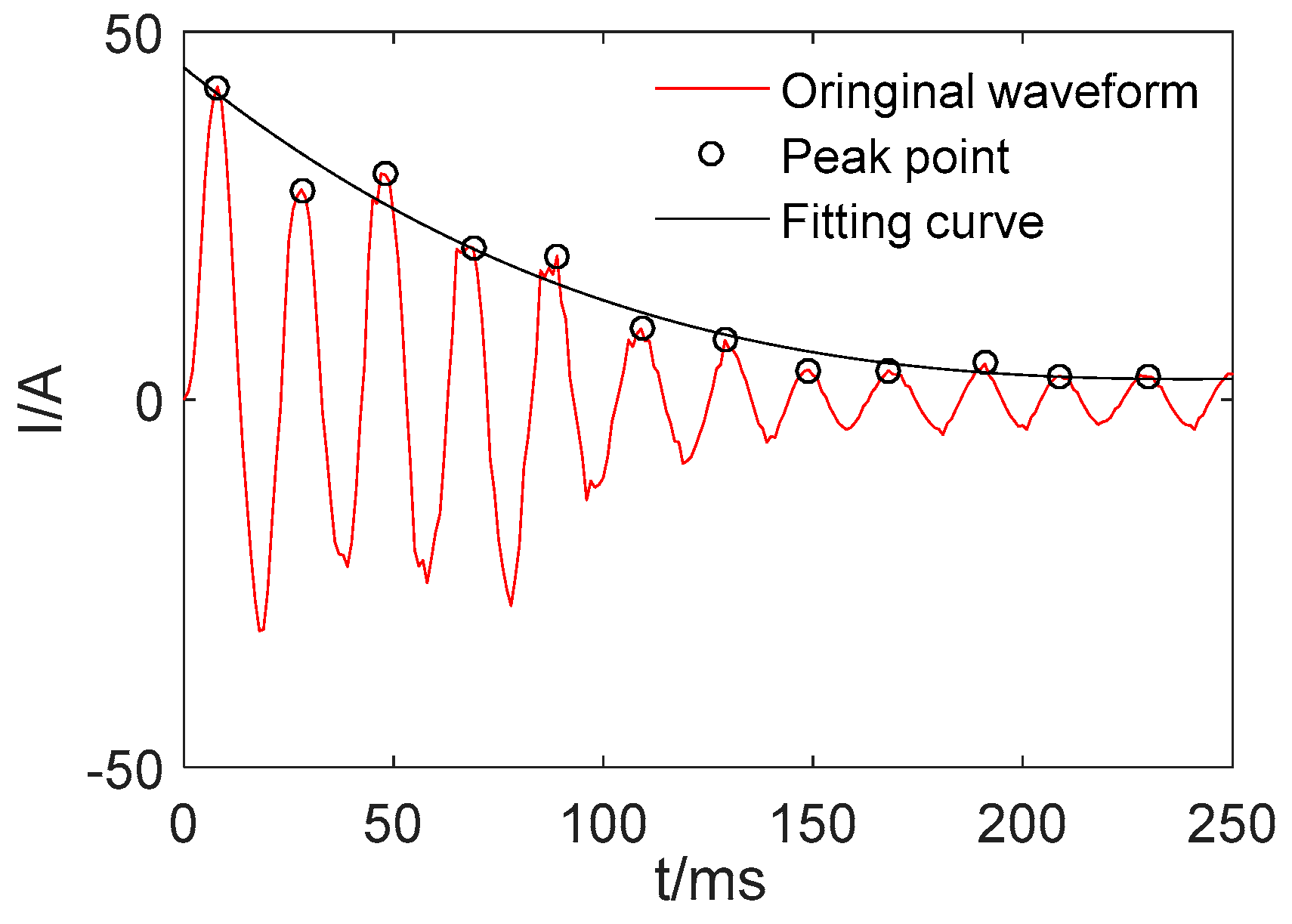
4.2. Simulation Comparison and Test of No-Load Starting Performance of Prototype

In order to verify the inhibitory effect of the composite coil group on the starting current, the self-starting process (mode 1) and the asynchronous starting process (mode 2) of the prototype are simulated and analyzed in the finite element method. In addition, a new model on the basis of the prototype is established, which replaces the composite coil group by the common coil. It is required that the size of the stator and core length of the two models are all the same, with the structure of the rotor winding changed barely. The model has the same port connection with the prototype, and the self-starting mode of the model is called mode 3.
As Figure 14 shows, the three modes can reach a steady state at 150 ms. Therefore, 0–150 ms can be regarded as the starting phase. Because mode 2 will short the control winding, the power winding is subjected to a higher starting current. The mode 2 is about twice the peak value of the starting current of mode 1, and the mode 2 is about 3–4 times the peak value of current in the steady state of mode 1. When mode 1 and mode 3 are stable, the peak values of currents corresponding to the two modes are relatively close. But the starting currents are quite different. The mode 3 is about 3–4 times the peak value of current in the steady state of mode 1. In summary, the use of composite coils in the rotor windings can effectively reduce the starting current. It can also be seen from Figure 14 that the current of the PW is slightly larger than CW. It is due to the smaller phase resistance of the PW which is caused by the smaller pitch.
The magnetic flux density cloud map and the tooth magnetic density distribution diagram of three starting modes above are shown in Figure 15 and Figure 16. The selected time is t = 18 ms, with setting 1.8 T as the upper limit of the flux density in the magnetic flux density cloud map.
It can be seen from Figure 15c that there are three obvious saturation points in the stator winding part when the motor starting with the rotor winding uses a common coil, and there are some small ranges of saturation. By contrast, the saturation degree is lower when starting asynchronously, but there is still some apparent saturation. However, there is no saturation in the cloud map of the rotor winding with the composite coil.
Furthermore, it can be seen clearly from Figure 16 that the magnetic density is less than 1.5 T with a maximum value of 1.37 T when starting in mode 1, and the saturation degree is not high. When starting in mode 3, however, the maximum magnetic density is higher than 1.5 T, and the maximum value is 1.75 T, and the saturation degree is higher. Finally, when the motor is starting in mode 2, the maximum value of stator tooth density is over 2.0 T. From the analysis above, it can be concluded that using composite coil group for the motor can effectively reduce the starting current.
The results of simulation and conclusions are verified by prototype tests below. By making the motor start in mode 1 and 2, the phase current waveforms of PW and CW are measured separately. The phase current waveforms of PW and CW are shown in Figure 17, while the prototype does not connect to the load, and the final speed is stabilized at 985 rpm.
Comparing the peak points indicated in Figure 17 and Figure 18 with Figure 14, it is found that the starting current waveforms of mode 1 and mode 2 have the same trend and there is only a small error in the numerical values. The peak current in the test results is higher than the simulated value, which may be due to the fact that the simulation does not take into account the slight influence factors, such as wind friction. Figure 17a,b are respectively the A-phase currents of CW and PW. It can be seen from Figure 17a that the peak value of the CW phase current is 15.5 A during starting, and then it is stabilized at the value 3.2 A. Figure 17b shows that the peak value of PW phase current is 18.95 A when the motor starts, with a following steady value of 4.0 A. Figure 18 shows that the peak value of the CW phase current is 23.5 A when the motor starts asynchronously and stabilized at 12.4 A.
Due to the financial constraints, the brushless doubly-fed motor with the common coil design of the rotor winding has not been developed. However, by comparing the test results of the mode 1 and mode 2 of the prototype with the simulation results, the test results of the prototype can be basically consistent with the simulation. This can explain the correctness of the finite element model. Therefore, even if the prototype of the ordinary coil is not designed, the theoretical correctness is also explained by comparing the simulation results.
According to the simulation and experimental results above, the starting peak currents of mode 1 and 2 attained by experiments are higher than the simulation results. The stable values of the current measured in the tests of mode 1 and 2 are close to the simulation results. The test results verify the correctness of the simulation results and theory. In other words, the test results verify that the composite coil structure can reduce the starting current, which means the referred value of the rotor winding is increased. According to the principle mentioned in Section 1, the starting torque can be increased.

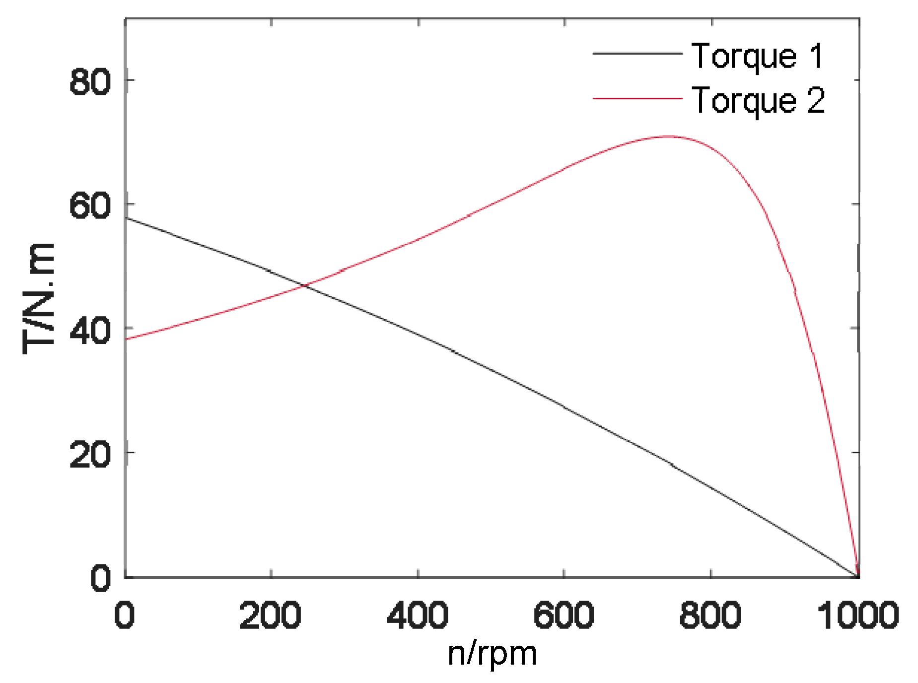
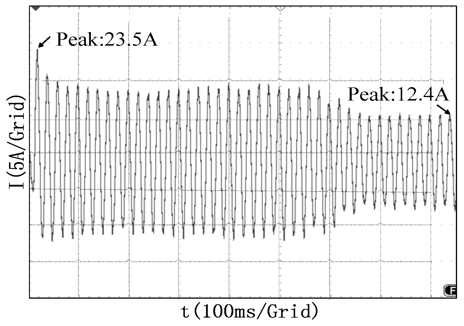
4.3. Simulation Comparison and Test of With-Load Starting Performance of Prototype

Simulations based on two models, mode 1 and 3, are conducted in order to further verify the inhibitory effect of the composite coils on the starting current. To compare the waveform visually, the peak point of the current waveform is fitted which can well represent the variation trend of the starting current. For example, only positive peaks are fitted in Figure 19.
The starting current fitting curves of mode 1 and 3 with different loads are shown in Figure 20. It can be seen from the Figure that the starting current of the two sets of windings in mode 1 is smaller than that of mode 3. The starting current of mode 3 increases, following the increase in load torque. However, the starting current of mode 1 changes slightly. On the other hand, the stable peak values of mode 1 and mode 3 are basically the same, while the fitting curve of mode 1 is slightly higher. It is caused by the precision of curve fitting and the selection of a function. Therefore, the results above show that the structure of the composite coils can effectively reduce the starting current.
Then, the load simulations and tests are carried out in mode 1 and 2 and compared to the finite element simulation results.
The finite element calculation values of steady current, the rotational speed parameters of the prototype with different loads, and the experimental values of the prototype are all shown in Table 2.
In Table 2, with the short-circuit of CW in mode 2, only a very low amplitude current is induced in the circuit of CW, which can be ignored during measurement. As shown in Table 2, the phase current values of mode 1 and mode 2 increase following the increase in applied load torque, and the experimental values of the prototype are very close to the Finite Element Analysis (FEA) results. Secondly, the rotational speed test value of mode 1 is still higher than 500 rpm with 20 N·m load, and the transition from starting state to running state can be completed, revealing excellent starting performance of the prototype.

5. Conclusions

In this paper, a novel BDFM using composite coil group is proposed. The principle and function of the structure are analyzed combining with a design example, and the simulation and prototype experiments are carried out, with several conclusions drawn as follows:
(1)
When the motor starts, the composite coil structure can reduce the effective coil-turns of the rotor winding, hence increasing the referred value of the rotor winding to reduce the starting current and improve the starting torque.
(2)
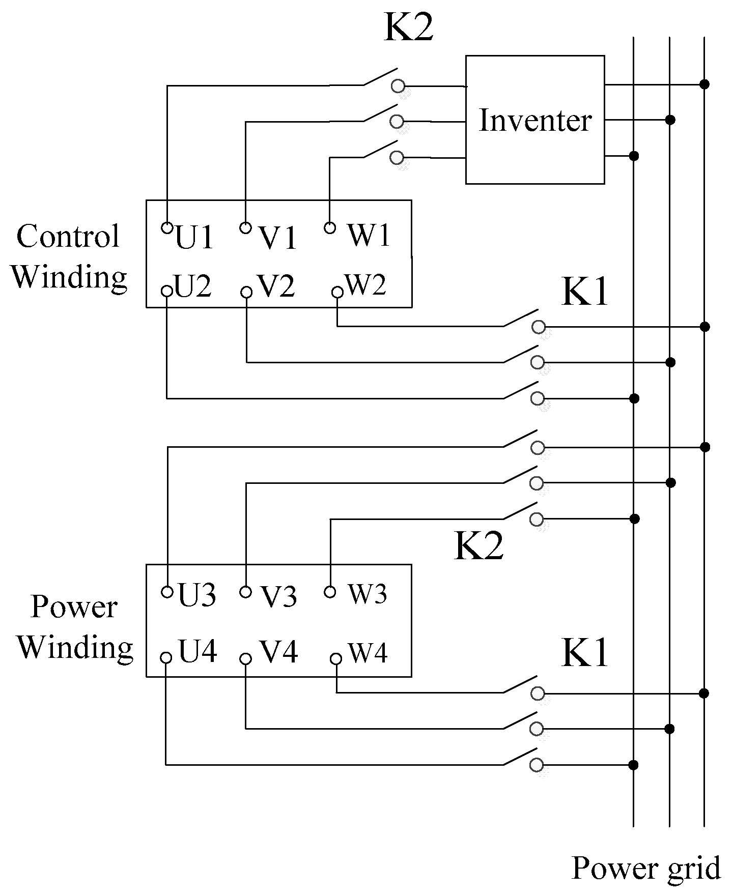
Through the analysis of the operating state and the principle of the composite coil, we find that magnetic fields with different pole-pairs make the composite coil have different operating states. Therefore, we use the winding designed by the pole-changing method for the stator to control the operating state of the composite coil.
(3)
On comparing the simulation and test results of the three modes, the starting current is effectively suppressed in mode 1, especially at the moment of start-up. Meanwhile, the prototype has been confirmed to have a better load-carrying performance.
Since the starting current of the prototype is effectively suppressed, the prototype can be directly connected to the grid even with a load. Moreover, the prototype can be switched by the feedback signal of speed, so the prototype system is safe and reliable. The prototype designed by the pole-changing method attains the maximum torque at the start moment, which avoids the rising process of torque. The speed of the motor rises slowly during the starting state, and the torque decreases as the speed increases, this advantage can reduce the loss to the conveyor belt significantly in applications where transport to the conveyor is used. In summary, the motor designed by this method can effectively reduce the starting current and increase the starting torque, while improving the starting performance of the brushless doubly-fed motor. The application of this design method has specific guiding importance for industrial applications.

Author Contributions

Data curation, C.K.; Investigation, Q.C.; Methodology, C.C.; Writing—original draft, Z.R.; Writing—review and editing, T.R.

Funding

This research received no external funding.

Acknowledgments

This work was supported by the National Natural Science Foundation of China (51377040).

Conflicts of Interest

The authors declare no conflict of interest.

References

  1. Abdi, S.; Abdi, E.; Oraee, A.; Mcmahon, R. Optimization of magnetic circuit for brushless doubly fed machines. IEEE Trans. Energy Convers. 2015, 30, 1611–1620. [Google Scholar] [CrossRef]
  2. Liu, Y.; Ai, W.; Chen, B.; Chen, K.; Luo, G. Control design and experimental verification of the brushless doubly-fed machine for stand-alone power generation applications. IET Electr. Power Appl. 2016, 10, 25–35. [Google Scholar] [CrossRef]
  3. Abdi, S.; Abdi, E.; McMahon, R.A. A study of unbalanced magnetic pull in brushless doubly fed machines. IEEE Trans. Energy Convers. 2015, 30, 1218–1227. [Google Scholar] [CrossRef]
  4. Han, L.; Ou, X.; Du, J.; Han, X.; Guo, Y. Study of Direct Coupling in Stator Dual Windings of a Brushless Doubly Fed Machine. IEEE Trans. Energy Convers. 2017, 32, 974–982. [Google Scholar] [CrossRef] [Green Version]
  5. Oraee, A.; Abdi, E.; Abdi, S.; McMahon, R.A.; Tavner, P.J. Effects of rotor winding structure on the BDFM equivalent circuit parameters. IEEE Trans. Energy Convers. 2015, 30, 1660–1669. [Google Scholar] [CrossRef]
  6. Xiong, F.; Wang, X. Design of a low-harmonic-content wound rotor for the brushless doubly fed generator. IEEE Trans. Energy Convers. 2014, 29, 158–168. [Google Scholar] [CrossRef]
  7. Xia, C.; Hou, X. Study on the Static Load Capacity and Synthetic Vector Direct Torque Control of Brushless Doubly Fed Machines. Energies 2016, 11, 966. [Google Scholar] [CrossRef]
  8. Xia, C.; Hou, X.; Chen, F. Flux-Angle-Difference Feedback Control for the Brushless Doubly Fed Machine. Energies 2018, 11, 71. [Google Scholar] [Green Version]
  9. McMahon, R.; Tavner, P.; Abdi, E.; Malliband, P.; Barker, D. Charac-terising rotors for brushless doubly-fed machines (BDFM). In Proceedings of the Electrical Machines (ICEM), Rome, Italy, 6–8 September 2010; pp. 1–6. [Google Scholar]
  10. Wang, X. A new brushless doubly-fed machine with a wound-rotor change-pole winding. Proc. Chin. Soc. Electr. Eng. 2003, 23, 108–111. [Google Scholar]
  11. Zhang, J.; Wang, X.; Wu, T.; Xiong, F.; Kan, C. The principle and harmonic analysis of a new BDFM with tooth harmonic wound rotor using as a generator. In Proceedings of the 2008 International Conference on Electrical Machines and Systems, Wuhan, China, 17–20 October 2008; pp. 3622–3626. [Google Scholar]
  12. Wijaya, F.D.; Kusumawan, S.A.; Prabowo, H. Reducing induction motor starting current using magnetic energy recovery switch (MERS). In Proceedings of the 2014 6th International Conference on Information Technology and Electrical Engineering (ICITEE), Yogyakarta, Indonesia, 7–8 October 2014; pp. 1–6. [Google Scholar]
  13. Kong, M.; Wang, X.; Li, Z.; Nie, P. Asynchronous operation characteristics and soft-starting method for the brushless doubly-fed motor. IET Electr. Power Appl. 2017, 11, 1276–1283. [Google Scholar] [CrossRef]
  14. Arabaci, H.; Bilgin, O. Effects of rotor faults in squirrel-cage induction motors on the torque-speed curve. In Proceedings of the XIX International Conference on Electrical Machines-ICEM 2010, Rome, Italy, 6–8 September 2010; pp. 1–5. [Google Scholar]
  15. Belhadi, M.B.; Kolli, A.; Krebs, G.; Marchand, C. Evaluation of torque-speed curve of switched reluctance motor with segmental rotor. In Proceedings of the 2012 XXth International Conference on Electrical Machines, Marseille, France, 2–5 September 2012; pp. 250–255. [Google Scholar]
  16. Azar, Z.; Zhu, Z.Q.; Ombach, G. Investigation of Torque–Speed Characteristics and Cogging Torque of Fractional-Slot IPM Brushless AC Machines Having Alternate Slot Openings. IEEE Trans. Ind. Appl. 2012, 48, 903–912. [Google Scholar] [CrossRef]
  17. McMahon, R.A.; Roberts, P.C.; Wang, X.; Tavner, P.J. Performance of BDFM as generator and motor. IEE Proc.-Electr. Power Appl. 2006, 153, 289–299. [Google Scholar] [CrossRef]
  18. Jiang, D.; Li, H.; Xianpeng, O.; Xuefeng, H. Experimental Study of Brushless Doubly-Fed Machine with Cage Rotor at the Asynchronous Operation Mode. Proc. CSEE 2016, 36, 3964–3972. [Google Scholar]
Figure 1. The T-s curve.
Energies 12 01157 g001
Figure 2. A rotor winding branch composed separately of common coils and composite coils.
Energies 12 01157 g002
Figure 3. Running condition.
Energies 12 01157 g003
Figure 4. Starting condition.
Energies 12 01157 g004
Figure 5. The connection of rotor windings.
Energies 12 01157 g005
Figure 6. Slot electrical potential star Vectogram (p = 4).
Energies 12 01157 g006
Figure 7. Slot electrical potential star Vectogram (p = 3).
Energies 12 01157 g007
Figure 8. The wiring structure of the stator winding.
Energies 12 01157 g008aEnergies 12 01157 g008b
Figure 9. Stator and rotor winding wiring diagram under different working conditions.
Energies 12 01157 g009aEnergies 12 01157 g009b
Figure 10. The port wiring diagram of the prototype when it is overall running.
Energies 12 01157 g010
Figure 11. Stator, rotor structures, and test platform of the prototype.
Energies 12 01157 g011
Figure 12. The torque-speed curve.
Energies 12 01157 g012
Figure 13. The fitting curve of transient torque-speed.
Energies 12 01157 g013
Figure 14. The phase current of the stator winding under no load.
Energies 12 01157 g014
Figure 15. Cloud map of magnetic flux density.
Energies 12 01157 g015aEnergies 12 01157 g015b
Figure 16. Tooth magnetic density distribution map of stator winding corresponding to different starting modes.
Energies 12 01157 g016aEnergies 12 01157 g016b
Figure 17. Test waveforms of stator winding phase current of BDFM prototype (mode 1).
Energies 12 01157 g017
Figure 18. Test waveforms of the phase current of the stator winding in asynchronous mode.
Energies 12 01157 g018
Figure 19. Original waveform and fitting curve.
Energies 12 01157 g019
Figure 20. Comparison of peak fitting curves of starting current.
Energies 12 01157 g020aEnergies 12 01157 g020b
Table 1. The parameters of the brushless doubly-fed machine.
ItemValue (mm)
Stator Outer Diameter215
Stator Inner Diameter130
Length of the Gap0.4
Rotor Outer Diameter129.2
Rotor Inner Diameter50
Length of the Core190
Table 2. Comparison of the current and speed of the prototype with the load. TEST: The results of the test; FEA: The results of the FEA; PW: Power winding; CW: Control winding.
Torque (N·m)Mode 1Mode 2
CW/APW/An/rpmCW/APW/An/rpm
TESTFEATESTFEATESTFEATESTFEATESTFEATESTFEA
53.23.34.03.9909907--13.112.6503498
103.43.34.04.0828833--15.314.7491487
153.43.55.04.9729735--18.118.3473460
203.64.05.65.4634645--20.118.5459440

