Article

An Improved Droop Control Method for Voltage-Source Inverter Parallel Systems Considering Line Impedance Differences

1
College of Electrical and Electronics Engineering, Harbin University of Science and Technology, Harbin 150080, China
2
College of Rongcheng, Harbin University of Science and Technology, Rongcheng 264300, China
*
Author to whom correspondence should be addressed.
Energies 2019, 12(6), 1158; https://doi.org/10.3390/en12061158
Submission received: 19 February 2019 / Revised: 13 March 2019 / Accepted: 21 March 2019 / Published: 25 March 2019

Abstract

:
In this paper, the effect of the line impedance difference between various inverters on power sharing with the traditional droop control method is fully analyzed. It reveals that the line impedance difference causes a significant reactive power error. An improved droop control method to eliminate the reactive power errors caused by the line impedance errors is proposed. In the proposed method, a voltage compensation determined by the actual reactive power error between the local inverter and the average one is added into the local voltage reference based on the CAN communication. Even when the communication is interrupted, the controller will operate with the last value of the average power, which still outperforms the traditional method. The effectiveness of the proposed control method is verified by simulation and experimental results, which show the proposed method possesses the better power sharing performance and dynamic response.

1. Introduction

Uninterruptable power supplies (UPSs) which are used to supply AC power to sensitive loads in some environments such as banks, transportation, Internet Data Centers (IDCs), are becoming more and more important [1,2,3,4]. Parallel operation is an important way to improve the reliability of the power system. Compared with a single unit, a parallel system has the following advantages: low-cost, easy to maintain, redundancy and better capacity expansion [5,6,7,8].
To get better power sharing, the droop control method is widely used to compensate the unbalance between the active and reactive power by slightly adjusting the frequency and amplitude of the output voltage. Although the possibility of performing autonomous power sharing among UPS units exists, the traditional droop control has several limitations. The conflict between power sharing accuracy and voltage bias is a well-known tradeoff of droop control [9]. The power sharing accuracy can also be affected by other factors; the line impedance being one of them [8]. Influenced by the mismatch of the line impedance, the traditional droop control fails to achieve power sharing accuracy, and in some situations, it can make the system unstable [10]. To solve the issue, some improved methods have been reported in the literature.
The design of virtual output impedance is considered an effective way to prevent power coupling and improve power sharing. A comprehensive adjustment of the virtual output impedance concept is presented in [11,12,13,14], which indicated that the closed-loop output impedances can be negligible in the steady state with proper design of the voltage controller. These methods only focus on the mismatch in the output impedances of the closed-loop controller but neglect the mismatch of the physical line impedance. A high-gain droop control approach is employed in [9], but when the fluctuation of the power is large, it will cause poor power quality. Adaptive virtual impedance has been used in [15] to achieve accurate power sharing, but this method may reduce the dynamic response with non-linear loads. An output voltage reference which can be adjusted by the virtual impedance based on output current feedback is proposed in [12,16], however this method can degrade the system power quality. Based on the assumption that the line impedance is small, a control strategy with inductive virtual impedance was introduced in [17] to ensure accurate power sharing. In [18], the concept of virtual impedance is extended to negative impedance just by offsetting part of line resistance by the virtual negative resistance. When the same effect as in [17], is achieved, the power quality is improved. However the dynamic performance with this method needs further analysis.
Anti-droop control [19] and the genetic algorithm [20] are proposed to decrease the reactive power sharing error, but these methods require knowledge of the power line impedance. In [21,22], the line impedance can be estimated by the harmonic of the load voltage, but this method needs extra sensors and involves a complicated harmonic analysis algorithm. Besides, this method may not be valid for longer lines. In [23], a line impedance identification approach is proposed by means of constant power control. However, this method needs precise power calculation. In [24], a harmonic signal injection technique is studied for the measurement of the line impedance, which may decrease the output voltage accuracy and influence system stability with non-linear loads. Besides, although the line impedance can be estimated, the temperature, humidity and stray parameters will also produce a deviation between the theoretical value and the practical one.
In order to improve reactive power sharing, the adaptive droop control method [25,26] is proposed in which the voltage droop slope is dynamically adjusted to compensate for the drop voltage across the line impedance. Although the accurate power sharing can be achieved under steady state conditions, the dynamic performance, which is a very important characteristic for UPS parallel systems [1,2,3,4,5,6,7,8,9], would degrade. The line impedance regulator (LIR), which is connected in series into the coupling line to induce a controllable counter voltage, is proposed in [27] to compensate the line impedance voltage drop. This approach depends on two factors: the estimation of the line impedance voltage drop by the predetermined line impedance value and the measurement of the current flowing through the line. This approach results in relatively improved power sharing performance between two nodes, but it needs further investigation for a multi node scenario.
Decentralized [28], fully coupled [7] or centralized [29,30,31] communication links can also be used in droop control methods, through which the output voltage and current of each unit can be gathered, but the power sharing performance in these cases is susceptible to link failures.
In this paper, a novel droop control method considering the difference of the line impedance between each unit is proposed. This method directly adjusts the voltage reference in a local controller by the error between the local reactive power and the average one to eliminate the power sharing error and accordingly to achieve accurate power sharing and better dynamic performance. The results of simulation and experimental are given to verify the correctness and feasibility of the proposed control method. Compared with the other solutions mentioned above, the major work and contributions of this paper include several parts which can be summarized as follows:
(1)
The effect of the mismatch in line impedance on the power sharing with the traditional droop control method is not well analyzed so far. This paper systematically analyzes it in two different ways.
(2)
The communication in this proposed method is just used to set the reference voltage instead of acting in the tuning control loop, therefore the power sharing is not susceptible to any delays in the communication. In addition, when the communication is interrupted, the controller can operate with the last value before the communication failure occurred, which has the advantages of high power sharing accuracy and robustness to the communication interrupt.
(3)
This proposed method does not need any complicated algorithms or the value of the line impedance.
(4)
Simulations and experiments are carried out with non-linear loads, which can better verify the advantages of the proposed method on the performance of dynamic, power sharing and voltage accuracy compared to those in [20,21,22,23,24,25,26,27,28,29,30,31,32,33] with linear loads.

2. Problem Statement

2.1. The Traditional Droop Control Method

Figure 1 shows the diagram of the parallel system with two units connected to the load.
The inverter output apparent power is Soi, which can be expressed by Equation (1):
S o i = P o i * + j Q o i * = E o i V o e j ( δ i φ o i ) V o 2 e j δ i R l i 2 + X l i 2 = E o i V o cos ( δ i φ o i ) V o 2 cos δ i R l i 2 + X l i 2 + j E o i V o sin ( δ i φ o i ) V o 2 sin δ i R l i 2 + X l i 2
where E o i φ o i , P o i * and Q o i * are the output voltage, active and reactive power of the i-th inverter respectively; V o is the amplitude of load voltage, setting the phase angle is zero; R l i + j X l i is the line impedance of the i-th inverter. Generally X l i R l i , that is, the phase angle δi can be set 90° [2,3,4]. The active and reactive power of each unit can be shown as Equation (2):
{ P o i * = E o i V o sin φ o i X l i Q o i * = E o i V o cos φ o i V o 2 X l i
The phase shift angle φ o i is very small. Therefore, the active power and reactive power of each unit can be regulated by the conventional droop control [20], shown as Equation (3):
{ w i = w * k θ d i P o i E i = E * k v d i Q o i
where w i and w * are the reference and nominal frequency, respectively; E i and E * are the reference and nominal voltage amplitude, respectively; k θ d i and k v d i are droop control coefficients of the i-th inverter; P o i and Q o i are the filtered active and reactive power of the i-th inverter, respectively.

2.2. The Limitation of The Traditional Droop Control against The Line Impedance Difference

The effect of the line impedance difference on the power sharing with the traditional droop control method is not well analyzed so far. To better analyze the limitations under this condition, this analysis is performed based on the individual outputs and the difference of the drop voltage across the line impedance respectively.

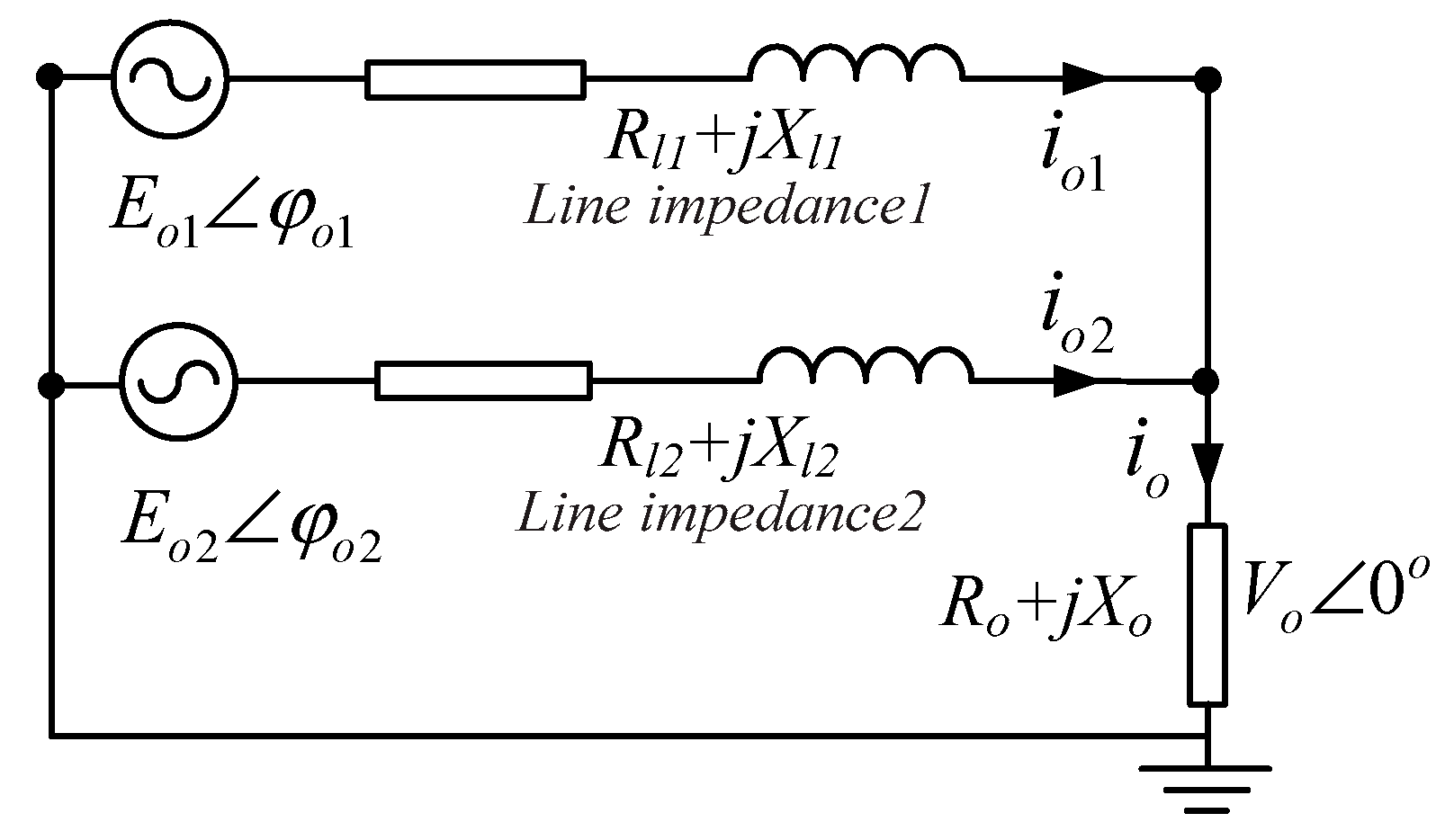
2.2.1. The Analysis Based on The Individual Outputs

Because w * , E * and the droop coefficients of each unit are the same as each other, in order to share the load power equally, only when the reference w i and E i of each unit are the same, the equations k θ d 1 k θ d 2 = P o 2 P o 1 and k v d 1 k v d 2 = Q o 2 Q o 1 can be held. By substituting Equation (2) into (3), the expressions of w i and E i can be obtained. After Laplace transformation [13], it yields:
w i ( s ) = w * X l i s X l i + k θ d i E o i V o
E o i = V o X l i k v d i + ( X l i k v d i V o ) 2 + 4 X l i k v d i E * 2
As can be seen from Equation (4), each inverter can be pulled into synchronization after regulating (according to the final value theorem shown as the Equation (6)):
e r r w = lim s 0 s E ( s ) = lim s 0 s [ w 1 ( s ) w 2 ( s ) ] = 0
It also indicates that the active power control is decoupled from the line impedance. From Equation (5), it can be seen that the output voltages of all units can be equal only when X l i k v d i = c o n s t . It also indicates that the reactive power control is coupled with the line impedance and needs improvement.

2.2.2. The Effect Analysis Based on The Droop Voltage Difference across The Line Impedance

Figure 2 shows the single-line diagram of two inverters with different line impedance.
Considering the line impedance of inverter 2 as reference, the difference of line impedance between the two inverters is given by Equation (7):
{ R = R l 1 R l 2 X = X l 1 X l 2
where Rl1 and Rl2, Xl1 and Xl2 are the resistance and reactance of the line impedance of inverter 1 and inverter 2, respectively. According to [15], the drop voltage across the line impedance ( E o i ) can be expressed by Equation (8):
{ E o 1 X l 1 Q o 1 + R l 1 P o 1 V 0 E o 2 X l 2 Q o 2 + R l 2 P o 2 V 0
By setting R l 2 = R and X l 2 = X , Equation (9) can be obtained:
{ E o 1 ( X + X ) Q o 1 + ( R + R ) P o 1 V 0 = X Q o 1 + R P o 1 V 0 + X Q o 1 + R P o 1 V 0 E o 2 X Q o 2 + R P o 2 V 0
so the output voltage of each inverter can be expressed by (10):
{ E o 1 = E o 1 + V o E o 2 = E o 2 + V o
From (10) and (3), Equation (11) can be obtained:
E o 1 E o 2 = k v d 1 ( Q o 1 Q o 2 )
From (8) and (9), Equation (12) can be obtained:
E o 1 E o 2 = X ( Q o 1 Q o 2 ) V 0 + X Q o 1 + R P o 1 V 0
Combining equations (11) and (12), (13) can be obtained:
{ E o 1 E o 2 = X Q o 1 + R P o 1 V 0 + X k v d i = Δ E o Q o 1 Q o 2 = X Q o 1 + R P o 1 k v d i V 0 + X = Δ Q o
From Equation (13), it can be seen that only if X = R = 0 , E o 1 E o 2 is equal to zero. It means the drop voltage across line impedance of each unit is the same, that is, the mismatch of the line impedance causes a reactive power error between each unit. From the Equation (13), it is also shown that the bigger the line impedance is, the greater the voltage drops. In other word, the inverter with bigger line impedance would supply smaller reactive power.

3. The Proposed Droop Control Method and The Small-signal Stability Analysis

In this method, a voltage compensation determined by the reactive power error between the local inverter and the average one is added to the local voltage reference based on the CAN communication. By regulating the voltage reference in the local controller, the power sharing error can be reduced and the power sharing accuracy can be improved.

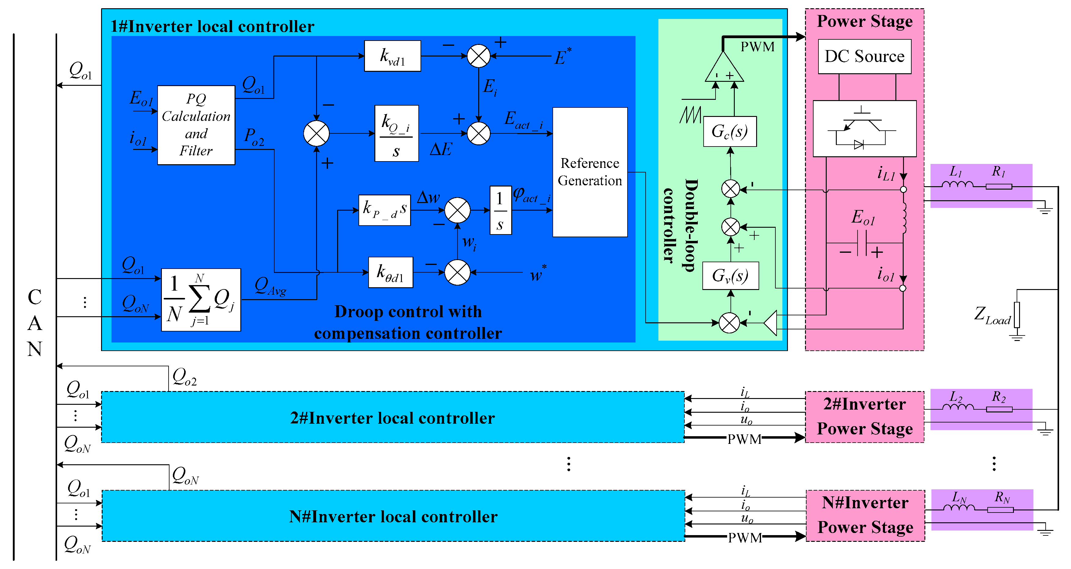
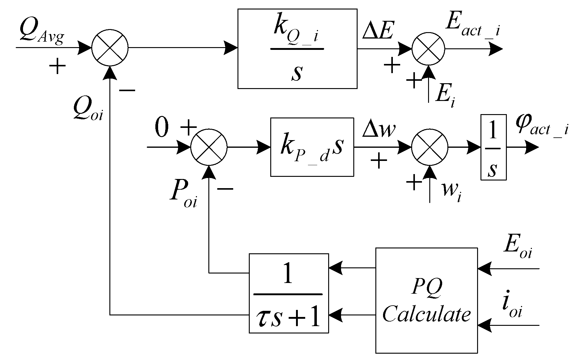
3.1. The Proposed Droop Control Method

Defining E o 1 + Δ E o = E o 1 , Equation (14) can be obtained based on (3) and (10):
E o 1 + Δ E o + V o = E * k v d 1 Q o 1
To modify the output voltage reference, E α can be compensated by utilizing the term Δ E o , shown as (15):
E o 1 + Δ E o + V o = ( E * + E α ) k v d 1 Q o 1
Therefore, Δ E o is essentially eliminated in (16):
E o 1 + V o = E * k v d 1 Q o 1
The proposed controller to tune the voltage reference and get accurate power sharing is shown in Figure 3.
The reference QAvg, which is calculated based on the reactive power of each unit through the communication, is used to modify the voltage reference by an integral controller. It is implemented in a local unit, as shown in Figure 3. The reference QAvg depends on the system load so it is a fixed value until the load varies. When the system load varies, the reference QAvg will be adjusted and the proposed droop controller starts to work in the local unit. In fact, the tuning process is based on the average reactive power of the parallel system. The communication is just used to set the QAvg instead of working within the tuning closed-loop. In other words, the accuracy of the reactive power sharing is unaffected by any communication delays in steady-state. When the communication is interrupted, the present average power would be lost, but the accurate power sharing can also be achieved based on the last value of QAvg due to the integral controller action as long as the system load is not changed. To reduce the risk of the loss of the communication, the redundant CAN bus communication scheme can also be adopted as well as the techniques mentioned in [22,23]. As analyzed above, though the inverters can finally be pulled into synchronization, the regulation process may take some time because of the integral element. Therefore, the differential controller can be applied with the purpose of improving the dynamic response.

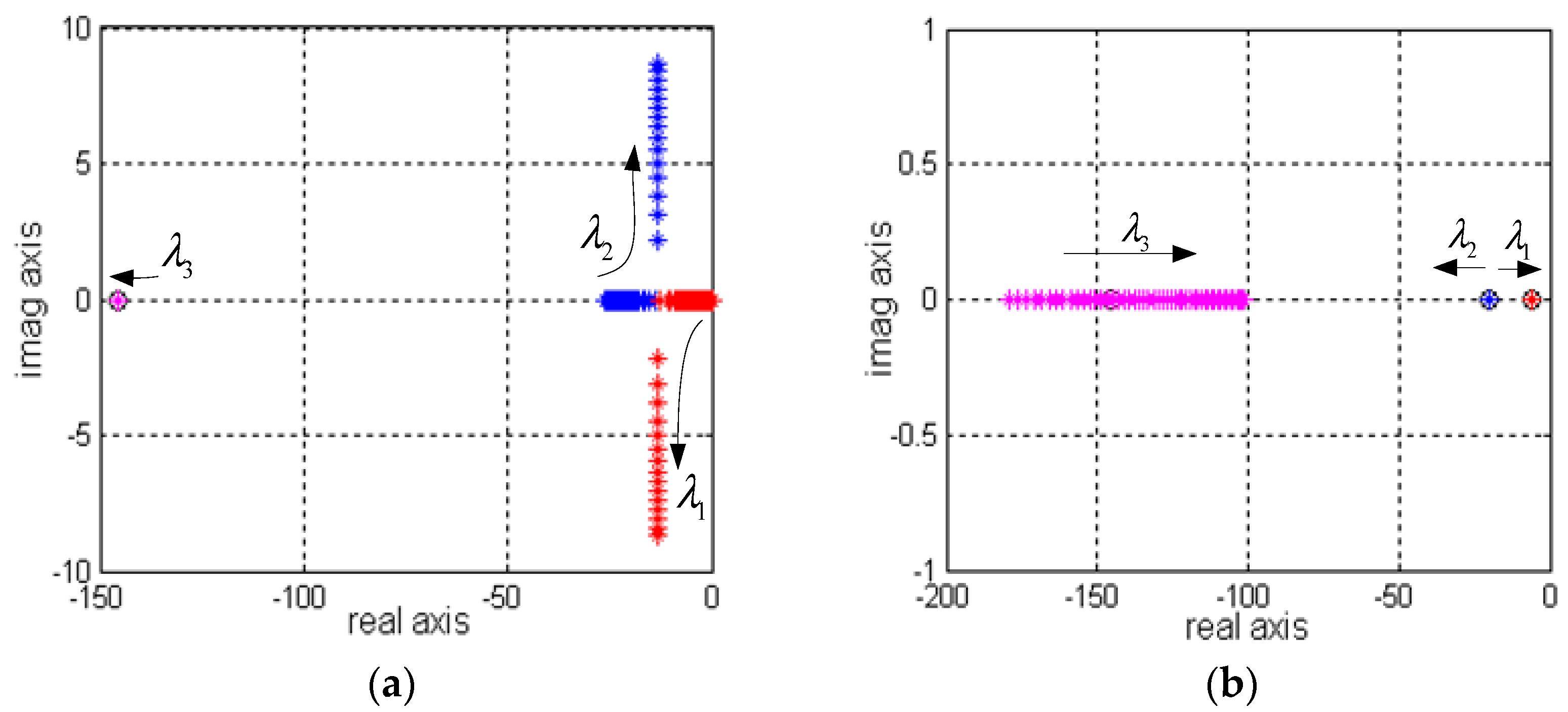
3.2. Small-Signal Stability Analysis

To analyze the stability of the proposed method, a small-signal model of the parallel control system is established. Based on the Equation (2) and modeling the low-pass filters with a first-order system, in which τ is time constant of the cut-off angular frequency, Equation (14) can be linearized as follows [24]:
{ p ^ o i = 1 τ s + 1 V o X l i ( e ^ o i sin φ o i + φ ^ i E o i cos φ o i ) q ^ o i = 1 τ s + 1 V o X l i ( φ ^ i E o i sin φ o i e ^ o i cos φ o i )
where p ^ o i , q ^ o i , e ^ o i and φ ^ o i denote small-signal perturbed values of E o i , φ o i , P o i * and Q o i * , respectively. The capital letters mean the steady-state value. Figure 4 shows the proposed droop control with the compensation controller.
If the voltage regulator and PLL regulator have no steady-state error, then E o i = E a c t _ i , φ o i = φ a c t _ i . From Figure 4, the equation can be expressed by (15):
{ E o i = E * k v d i Q o i + k Q _ i s ( Q A v g Q o i ) φ o i = ( w * k θ d i P o i s k P _ d P o i ) s
By perturbing (15), Equation (16) can be obtained:
{ e ^ o i = ( k Q _ i s + k v d i ) q ^ o i φ ^ o i = ( k P _ d + k θ d i s ) p ^ o i
Substituting (14) into (16), (17) can be obtained:
a s 3 + b s 2 + c s + d = 0
where the coefficients a,b,c and d are:
{ a = τ E o i V o X l i k P _ d cos φ o i + τ 2 X l i 2 b = 2 τ X l i 2 + E o i V o 2 k P _ d k v d i + τ E o i V o X l i k θ d i cos φ o i + E o i V o X l i k P _ d cos φ o i + τ V o X l i k v d i cos φ o i c = X l i 2 + E o i V o 2 ( k P _ d k Q _ i + k v d i k θ d i ) + E o i V o X l i k θ d i cos φ o i + τ V o X l i cos φ o i k Q _ i + V o X l i cos φ o i k v d i d = E o i V o 2 k θ d i k Q _ i + V o X l i k Q _ i cos φ o i
The coefficients k θ d i and k v d i of the droop controller can be designed using the traditional method, shown as (19):
{ Δ w max = k θ d i P o i max Δ V max = k v d i Q o i max
where P o i max and Q o i max are the maximum of active power and reactive power of the i-th inverter, respectively. Δ V max and Δ w max , are the maximum of amplitude and frequency deviation adopted by the pure traditional droop control method, respectively.
Figure 5 shows the root trajectories. There are three roots in this system and the arrows indicate the corresponding pole evolution as the coefficient increase. Figure 5a shows that the poles λ 1 and λ 2 become dominant with increasing k Q _ i . Figure 5b shows that the system is always determined by the two dominant poles λ 1 and λ 2 . With the increase of k P _ d , the system has better dynamic performance. The system is stable in this range because all three poles remain in the left half-plane.

4. Verification of The Proposed Method

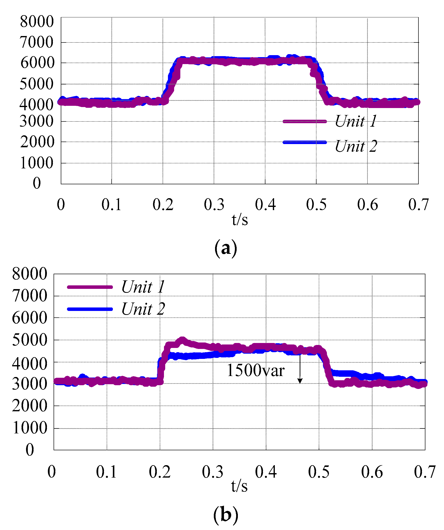
4.1. Simulation Verification

Taking the communication channel of reactive power from unit 1 to unit 2 for example, the corresponding communication system in Matlab/Simulink can be shown as Figure 6. The power calculated by each unit can be transmitted to another through the “transport delay” component in the Simulink library. By configuring the corresponding time of this component, it can simulate the information update delays of the communication system.
In addition, the communication interruption can also be simulated by adding the “latch” function, which is composed of the “switch” component in the Simulink library. There are three inputs in the “switch” component, which are numbered from top to bottom. The first and the third input ports are the data ports, which are connected to the signal Q2 and the signal Qo1 (the output of the “switch” component), respectively. The second input port is the control port, which is connected to the “pulse generation” component to simulate the interruption and restoration of the communication system. When the second input value is greater or equal to the threshold configured in the “switch” component, the signal from the first input passes through; otherwise, the signal from the third input passes through. In this simulation, the threshold is set to 1. According to the criterion mentioned above, the case when the communication is interrupted can be obtained as follows.
If the binary signal from “pulse generator1” is “0”, which means the communication is interrupted, the output Qo1 just holds the last received value instead of updating from Q2; otherwise, it indicates the communication system is restored, and the Qo1 can receive the value from Q2 again.
Assuming the time of the “transport delay” is set to 0.25 s and Q1 is a linear wave, the simulation waveforms can be shown as Figure 7. From Figure 7, Q2 lags behind Q1 0.25 s. When the communication is interrupted, Qo1 just maintains the last received value. When the communication is restored, Qo1 can continue to update the value from Q2.
In order to verify the proposed droop control method, a parallel system consisting of two inverters driven with non-linear load is established by Matlab/Simulink. The main parameters are shown in Table 1.
To verify the performance of the accuracy in terms of the power sharing and output voltage, the compared results between the traditional method and the proposed method are shown in simulation I. To verify the robustness to the communication interrupt and communication delay with the proposed method, the results are shown in simulation II and simulation III.
Simulation I
Figure 8 shows the simulation results by setting different line impedance with the 10 kVA non-linear load, introducing the proposed control method at 0.3 s. Before 0.3 s, the active power of each unit can be shared equally, however, the reactive power error between the two units is about 2000 var. This illustrates that the line impedance difference has a significant influence on the power sharing. When the proposed droop control method is introduced, the reactive power sharing can be greatly optimized. The output voltage is 219.3 V after adopting the proposed droop method. Compared to the output voltage in [11,12], it is much closer to 220 V.
Simulation II
Figure 9 shows the performance of the parallel system with the proposed method when the communication is disabled at 0.2 s and re-enabled at 0.5 s. From 0 s to 0.3 s, the total load of the system is 10 kVA. When the communication is disabled at 0.2 s, the power of the two units can also be shared equally because QAVG remains constant. At 0.3 s, the total power jumps from 10 kVA to 15 kVA. Theoretically, the value of QAVG at this time is 4.5 kvar, but because the communication is disabled, the value of QAVG at this time is still 3 kvar, which is the same as the value at 0.2 s. So the active power can’t be shared equally until the communication is re-enabled at 0.5 s. Figure 9a,b show the active power and reactive power in this process. Figure 9c,d show the current adjustment at 0.3 s and 0.5 s, respectively. The corresponding experiment will be shown in Experiment III.
Simulation III
Figure 10 shows the simulation results of the controller considering the effect of time delay mismatches among the communication channels. A delay of 100 ms is included in the communication link of unit 2, which means a 100 ms information update delay from unit 1. However, no delay is considered for unit 1, which means that the unit 1 can receive the information from unit 2 immediately. In addition, the load changes (10 kVA → 15 kVA → 10 kVA) have been introduced at 0.2 s and 0.5 s under this condition. Despite the fact two units cannot receive the information simultaneously, the power sharing can also be achieved since the load has not changed. That is, the accurate power sharing is not affected by the time delay in steady-state. When the load changes, the system can reach steady-state despite it would take some time. However, compared to the method in [12,17], the time delay has little effect on the system transients. The corresponding experiment will be shown later.

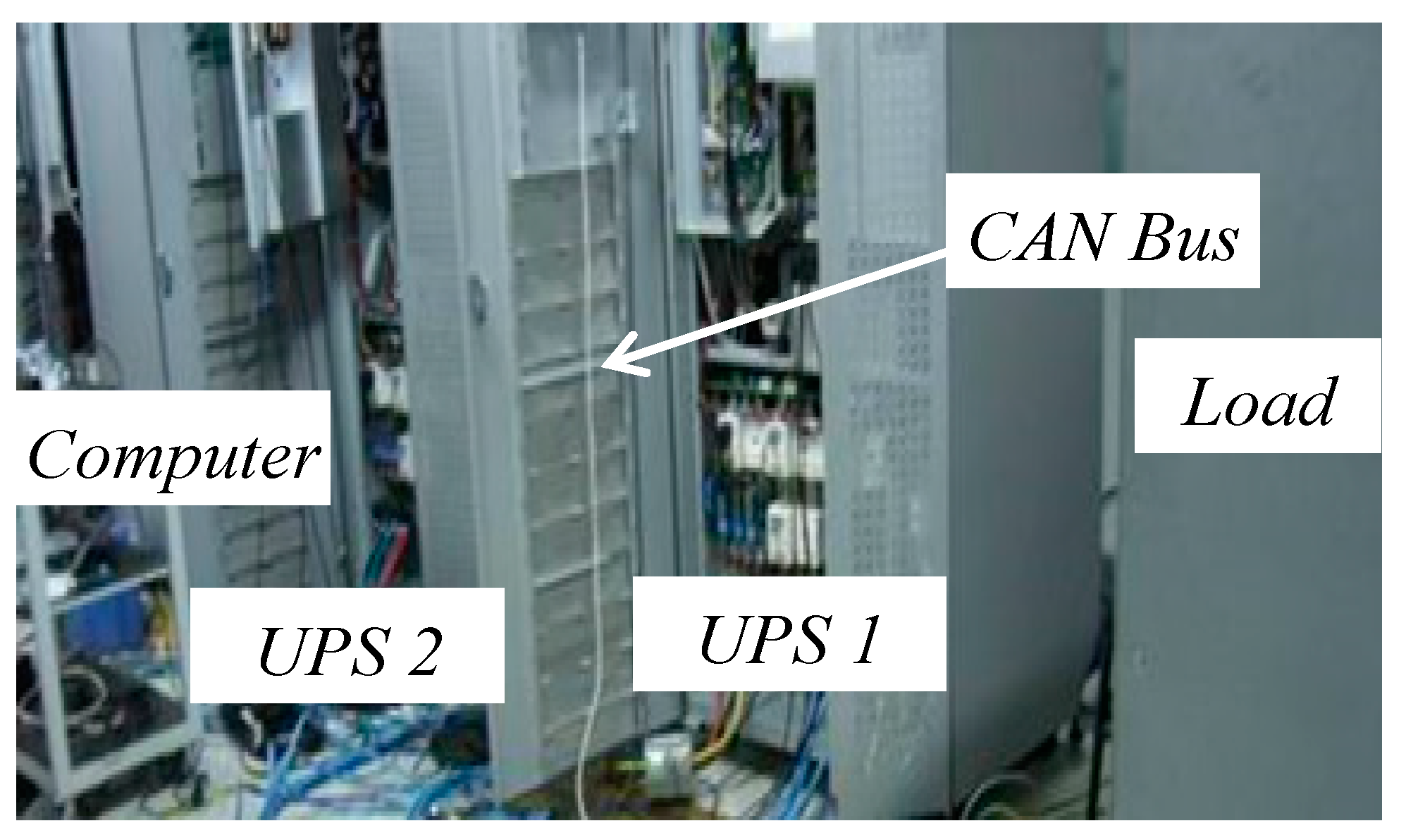
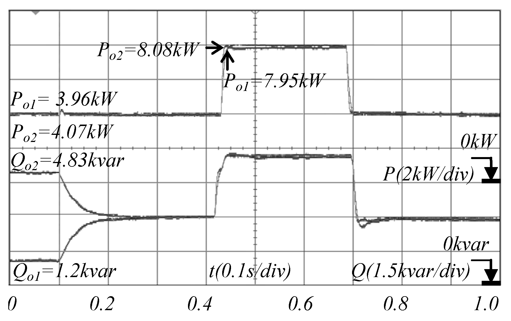
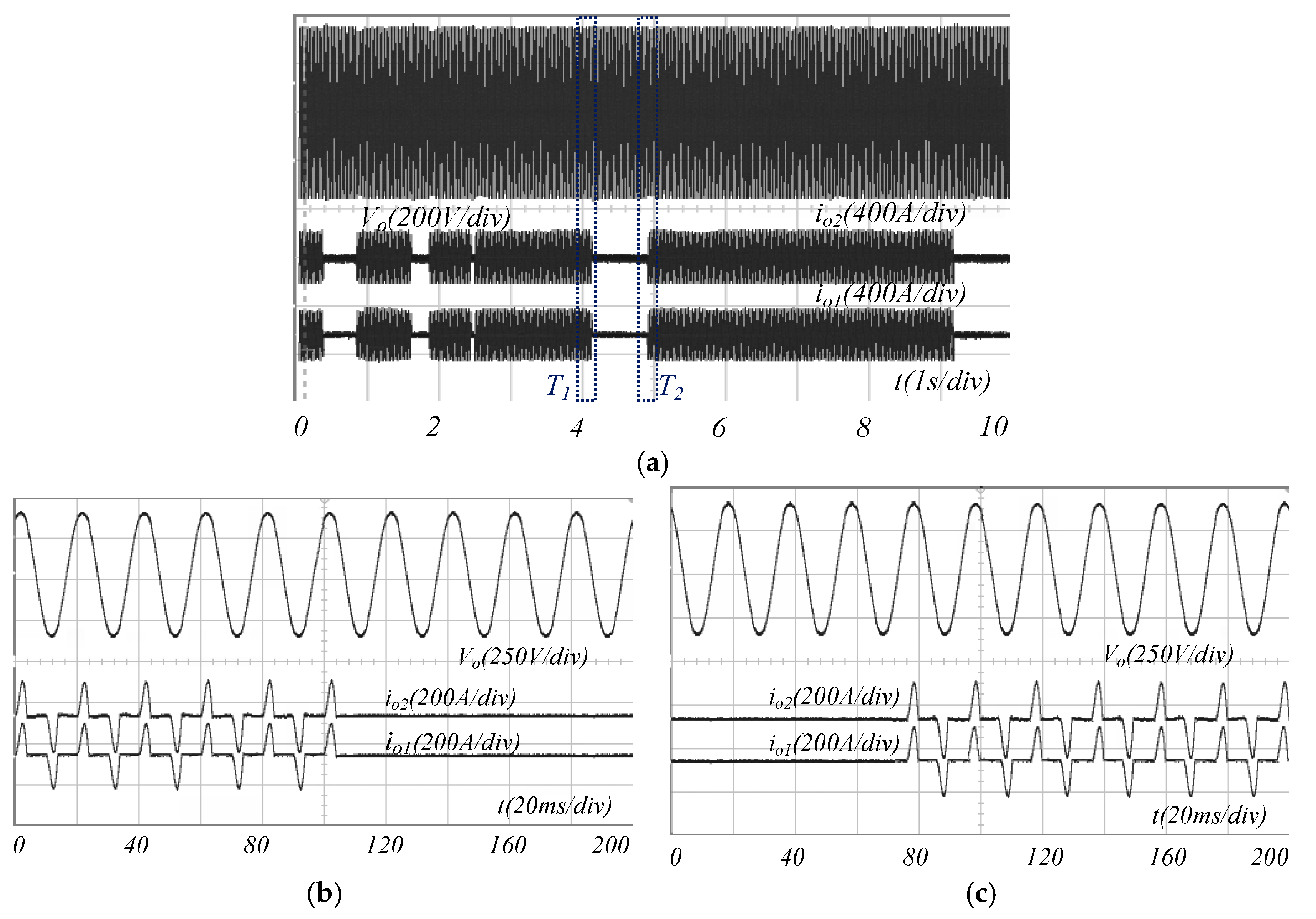
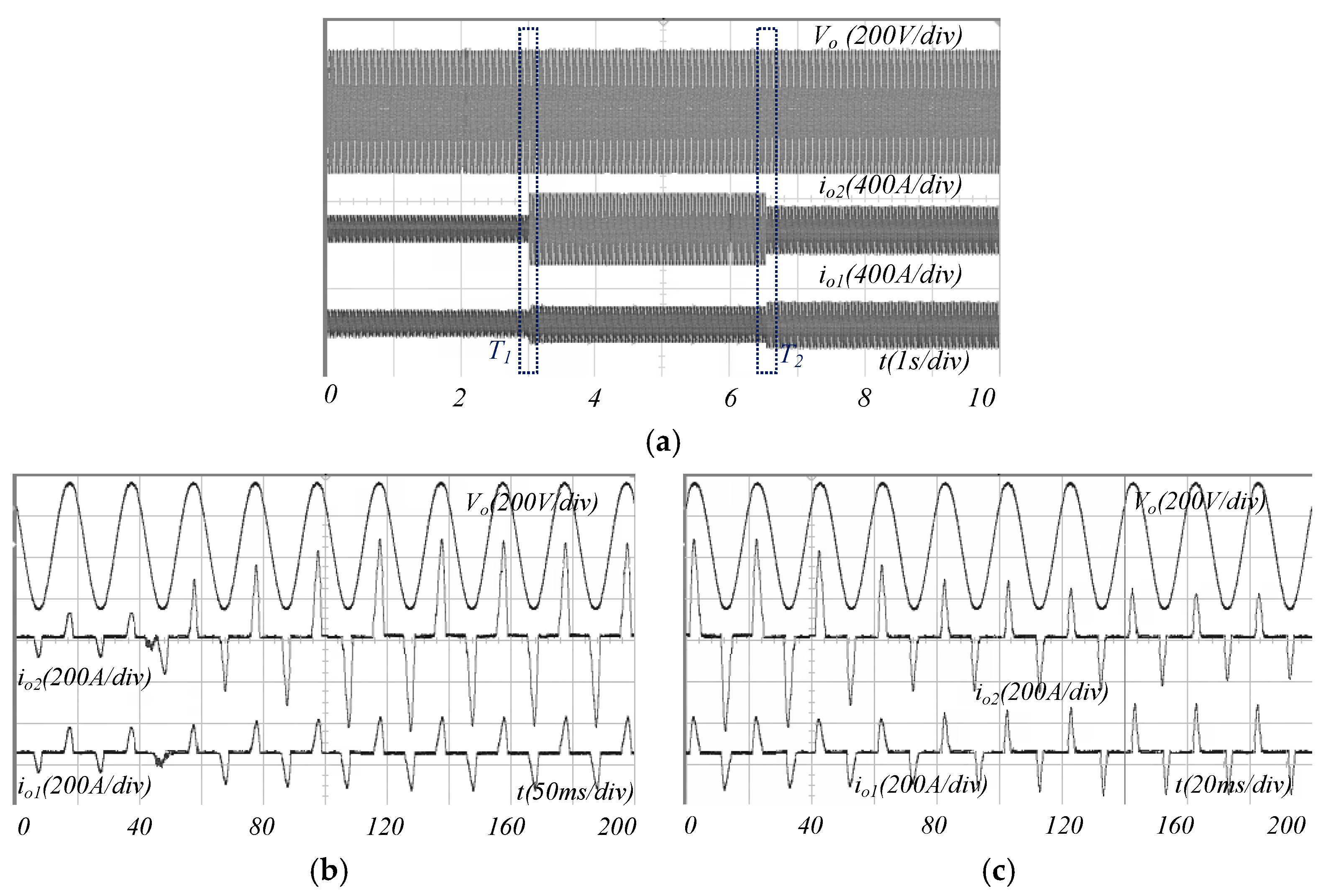
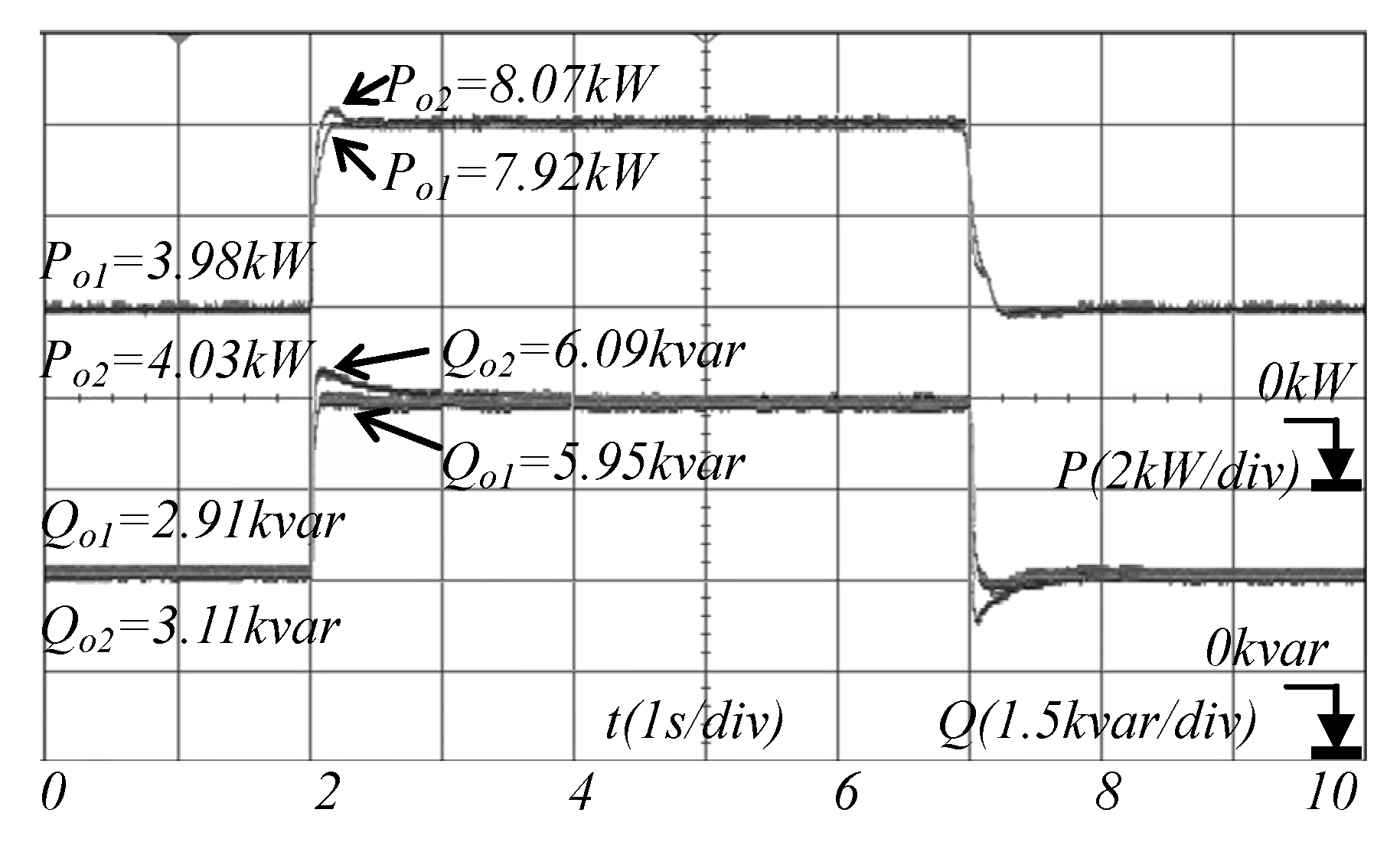
4.2. Experimental Verification

The parallel system consisting of 2 × 10 kVA inverters with 220 V/50 Hz rated voltage is established to verify the proposed droop control method, shown as Figure 11. The two units are both connected to the common non-linear load (PF = 0.8, HCF = 2.9). The communication of each unit is established through the CAN bus. The corresponding coefficients of the controllers are shown in Table 1. To evaluate the performance of the proposed method, the power sharing error Aerr_i is defined, shown as (19):
A e r r _ i % = A i A o _ i A o _ i × 100 %
where Ai is the actual value of the active or reactive power of the i-th unit, Ao_i is the desired value of the active or reactive power of the i-th unit.
Experiment I
With different line impedance, the proposed control method is enabled at 0.1 s and the abrupt non-linear load changes (10 kVA → 20 kVA → 10 kVA) are introduced at 0.42 s and 0.7 s, respectively. Figure 12 shows the waveforms of active power and reactive power during the process. It can be seen that, from 0 s to 0.2 s, with the traditional droop control method, the reactive power sharing accuracy is as poor as 59.33%. When the proposed method is enabled, the reactive power of two units can be adjusted so that they share equally (Qo2 = 3.01 kvar, Qo1 = 2.98 kvar) after less than 0.15 s. When the load varies, the reactive power and the active power can also be shared equally, demonstrating the effectiveness of the proposed method.
Experiment II
To further verify the dynamic performance of the proposed method with different line impedance, the abrupt non-linear load changes (0 kVA → 20 kVA → 0 kVA → 20 kVA →……) occur repeatedly. Figure 13 shows the output voltage and current waveforms. During the dynamic process of carrying non-linear load, very good current-sharing characteristics are achieved. More importantly, the distortion voltage of the parallel system is only 1.3%, which is much smaller than the 3.47% reported in [21] and is smaller than the 2.45% in [22]. This means the proposed controller has a negligible effect on the load voltage. It also illustrates that the proposed control method has better dynamic performance without sacrificing the property of output voltage.
Experiment III
Figure 14 and Figure 15 show the experimental waveforms when the communication is interrupted and restored under the condition of two units with the proposed method in different line impedance. In this experiment, the CAN bus cable is unplugged from one of the two units at 1.2 s and plugged back at 6.4 s. The non-linear load change (10 kVA → 20 kVA) is introduced at 3 s.
Figure 14a shows the waveforms of active power and reactive power during the process. From 1.2 s to 3 s, although the communication is lost, accurate power sharing can be achieved. At 3 s, due to the load changing, there is a slight active power error between the two units, but it can be quickly adjusted to zero. However, the reactive power sharing fails to achieve, which is explained in Section 2. Because each unit can hold the last received value, the reactive power sharing error is 7.8% during this time, which is still better than that with the traditional method shown as Figure 14b (the reactive power sharing error is about 45.2%). Until the CAN bus cable is plugged back at 6.4 s which means the communication is restored, the accurate power sharing can be get again.
Figure 15 shows the waveforms of voltage and current during this process in Experiment III with non-linear load.
We can see that the voltage is stable, and it only take less than 100 ms to achieve accurate current sharing after the communication is restored, unlike the method proposed in [11], which would take more than 2.2 s
Experiment IV
The performance of power sharing considering the communication delay is shown as Figure 16. The delay time in the communication channel to unit 2 is 100 ms, and no delay is included in the communication channel to unit 1. In this case, the unit 1 starts to adjust before unit 2 does, which has more effect on the system transients compared to the case when the delays are the same. In this experiment, the difference of the delay time between the two units is 100 ms, which is much longer than that in [15]. Also, the load changes (10 kVA → 20 kVA → 10 kVA) are introduced at the 2 s and 7 s.
As can be seen from Figure 16, the power sharing accuracy in steady-state is not affected by the time delay. In transient-state, although the accurate power sharing cannot be achieved immediately, it only takes about 250 ms to balance the power of the two units, which is much shorter than the time reported in [15]. The power difference between the two units can be negligible compared to the method described in [17].
It is worth mentioning that the delay time cannot be infinite in real CAN communication system. If the unit does not receive any information within the specified time (300 ms in this experiment), the communication can be considered to be interrupted. The performance is shown in the experiment III when communication is interrupted and restored.

5. Conclusions

In this paper, an improved droop control method is proposed to enhance the power sharing accuracy in a voltage-source inverter parallel system. The method of adding the voltage compensation into the voltage reference, which is determined by the reactive power error between the local unit and the average one, can reduce the power sharing error significantly. The power sharing accuracy and dynamic performance are enhanced accordingly. The performance of the proposed method after the communication is interrupted is also evaluated and it is verified that in this case the power sharing performance with the proposed method is still better than the traditional methods. The proposed method has the advantages of high power sharing accuracy, a simple algorithm and robustness to communication failures. The proposed method enhances the practicability of the droop control method and accordingly enhances the comprehensive performance of inverter parallel systems.
In the future, we plan to verify the performance of the proposed control strategy with unbalanced loads in UPS parallel systems. With the proposed method, units with different power rating should be considered. Especially, the case when the unit with higher power rating is connected to the higher line impedance should be further investigated deeply. It can also be extended to islanded microgrids.

Author Contributions

J.M. and X.W. conceived and designed the Testing and simulations; J.M. analyzed the data; J.M. and J.L. wrote the paper; H.G. checked the paper.

Funding

This research was funded by the National Natural Science Foundation of China grant number 51177031 and A Project of Shandong Province Higher Educational Science and Technology Program grant number J17KB136.

Conflicts of Interest

The authors declare no conflict of interest.

References

  1. Furtado, E.C.; Aguirre, L.A.; Tôrres, L.A.B. UPS parallel balanced operation without explicit estimation of reactive power—A simpler scheme. IEEE Trans. Circuits Syst. II Exp. Briefs 2008, 55, 1061–1065. [Google Scholar] [CrossRef]
  2. Guerrero, J.M.; Garciade Vicuna, L.; Matas, J.; Castilla, M.; Miret, J. Output impedance design of parallel-connected UPS inverters with wireless load-sharing control. IEEE Trans. Ind. Electr. 2005, 52, 1126–1135. [Google Scholar] [CrossRef]
  3. Liu, W.X.; Kim, J.M.; Wang, C.; Im, W.S.; Liu, L.M.; Xu, H. Power converters based advanced experimental platform for integrated study of power and controls. IEEE Trans. Ind. Inform. 2018, 14, 4940–4952. [Google Scholar] [CrossRef]
  4. Guerrero, J.M.; Vasquez, J.C.; Matas, J.; Castilla, M.; Vicuna, L.G. Control strategy for flexible microgrid based on parallel line-interactive UPS systems. IEEE Trans. Ind. Electr. 2009, 56, 726–736. [Google Scholar] [CrossRef]
  5. Lazzarin, T.B.; Guilherme, A.T.B.; Barbi, I. A Control strategy for parallel operation of single-phase voltage source inverters: Analysis design and experimental results. IEEE Trans. Ind. Electr. 2013, 60, 2194–2204. [Google Scholar] [CrossRef]
  6. Aamir, M.; Mekhilef, S. An online transformerless uninterruptible power supply (UPS) system with a smaller battery bank for low-power applications. IEEE Trans. Power Electr. 2017, 32, 233–247. [Google Scholar] [CrossRef]
  7. Zhang, Y.; Ma, H. Theoretical and experimental investigation of networked control for parallel operation of inverters. IEEE Trans. Ind. Electr. 2012, 59, 1961–1970. [Google Scholar] [CrossRef]
  8. Godoy, R.B.; Pinto, J.O.P.; Canesin, C.A.; Coelho, E.A.A.; Pinto, A.M.A.C. Differential-evolution-based optimization of the dynamic response for parallel operation of inverters with no controller interconnection. IEEE Trans. Ind. Electr. 2012, 59, 2859–2866. [Google Scholar] [CrossRef]
  9. Chen, T.P. Dual-modulator compensation technique for parallel inverters using space-vector modulation. IEEE Trans. Ind. 2009, 56, 3004–3012. [Google Scholar] [CrossRef]
  10. Han, H.; Liu, Y.; Sun, Y.; Su, M.; Guerrero, J.M. An improved droop control strategy for reactive power sharing in islanded microgrid. IEEE Trans. Power Electr. 2015, 30, 3133–3141. [Google Scholar] [CrossRef]
  11. Yao, W.; Chen, M.; Matas, J.; Guerrero, J.M.; Qian, Z.M. Design and analysis of the droop control method for parallel inverters considering the impact of the complex impedance on the power sharing. IEEE Trans. Ind. Electr. 2011, 58, 576–588. [Google Scholar] [CrossRef]
  12. Guerrero, J.M.; Matas, J.; Vicuna, L.G.; Castilla, M.; Miret, J. Decentralized control for parallel operation of distributed generation inverters using resistive impedance. IEEE Trans. Ind. Electr. 2007, 54, 994–1004. [Google Scholar] [CrossRef]
  13. Zhu, Y.X.; Zhuo, F.; Wang, F.; Liu, B.Q.; Zhao, Y.J. A wireless load sharing strategy for islanded microgrid based on feeder current sensing. IEEE Trans. Power Electr. 2015, 30, 6706–6719. [Google Scholar] [CrossRef]
  14. He, J.W.; Li, Y.W.; Blaabjerg, F. An enhanced islanding microgrid reactive power, imbalance power, and harmonic power sharing scheme. IEEE Trans. Power Electr. 2015, 30, 3389–3401. [Google Scholar] [CrossRef]
  15. Mahmood, H.; Michaelson, D.; Jiang, J. Accurate reactive power sharing in an islanded microgrid using adaptive virtual impedances. IEEE Trans. Power Electr. 2014, 30, 1605–1617. [Google Scholar] [CrossRef]
  16. Rowe, C.N.; Summers, T.J.; Betz, R.E.; Cornforth, D.J.; Moore, T.G. Arctan power–frequency droop for improved microgrid stability. IEEE Trans. Power Electr. 2013, 28, 3747–3759. [Google Scholar] [CrossRef]
  17. Wu, T.; Liu, Z.; Liu, J.; Wang, S.; You, Z. A unified virtual power decoupling method for droop controlled parallel inverters in microgrids. IEEE Trans. Power Electr. 2016, 31, 5587–5603. [Google Scholar] [CrossRef]
  18. Hou, G.; Xing, F.; Yang, Y.; Zhang, J. Virtual negative impedance droop method for parallel inverters in microgrids. In Proceedings of the 2015 IEEE 10th Conference on Industrial Electronics and Applications (ICIEA), Auckland, New Zealand, 15–17 June 2015; pp. 1009–1013. [Google Scholar]
  19. Gao, M.; Chen, M.; Wang, C.X.; Qian, Z.M. An accurate power-sharing control method based on circulating-current power phasor model in voltage-source-inverter parallel-operation system. IEEE Trans. Power Electr. 2018, 33, 4458–4476. [Google Scholar] [CrossRef]
  20. Li, Y.; Li, Y.W. Power management of inverter interfaced autonomous microgrid based on virtual frequency-voltage frame. IEEE Trans. Smart Grid. 2011, 2, 30–40. [Google Scholar] [CrossRef]
  21. Lee, C.T.; Hsu, C.W.; Cheng, P.T. A low-voltage ride-through technique for grid-connected converters of distributed energy resources. IEEE Trans. Ind. Appl. 2011, 47, 1821–1832. [Google Scholar] [CrossRef]
  22. Zhu, Y.; Zhuo, F.; Wang, F.; Liu, B.; Gou, R.; Zhao, Y. A virtual impedance optimization method for reactive power sharing in networked microgrid. IEEE Trans. Power Electr. 2016, 31, 2890–2904. [Google Scholar] [CrossRef]
  23. Tarasiuk, T.; Gorniak, M. Load sharing in ship microgrids under nonsinusoidal conditions—Case Study. IEEE Trans. Energy Convers. 2017, 32, 810–819. [Google Scholar] [CrossRef]
  24. Wang, L.; Chen, J.; Li, X.; Sun, X.; Guerrero, J.M. Fundamental impedance identification method for grid-connected voltage source inverters. IET Power Electr. 2014, 7, 1099–1105. [Google Scholar] [Green Version]
  25. Vasquez, J.C.; Guerrero, J.M.; Savaghebi, M.; Eloy-Garcia, J.; Teodorescu, R. Modeling, analysis, and design of stationary-reference-frame droop-controlled parallel three-phase voltage source inverters. IEEE Trans. Ind. Electr. 2013, 60, 1271–1280. [Google Scholar] [CrossRef]
  26. Andishgar, M.H.; Gholipour, E.; Hooshmand, R.A. An overview of control approaches of inverter-based microgrids in islanding mode of operation. Renew. Sust. Energy Rev. 2017, 80, 1043–1060. [Google Scholar] [CrossRef]
  27. Wang, X.; Li, Y.W.; Blaabjerg, F.; Loh, P.C. Virtual-impedance-based control for voltage-source and current-source converters. IEEE Trans. Power Electr. 2015, 30, 7019–7037. [Google Scholar] [CrossRef]
  28. Sun, X.; Hao, Y.; Wu, Q.; Guo, X.; Wang, B. A multifunctional and wireless droop control for distributed energy storage units in islanded AC microgrid applications. IEEE Trans. Power Electron. 2017, 32, 736–751. [Google Scholar] [CrossRef]
  29. Liang, H.; Choi, B.J.; Zhuang, W.; Shen, X. Stability enhancement of decentralized inverter control through wireless communications in microgrids. IEEE Trans. Smart Grid. 2013, 4, 321–331. [Google Scholar] [CrossRef]
  30. He, J.; Li, Y.W. An enhanced microgrid load demand sharing strategy. IEEE Trans. Power Electr. 2012, 27, 3984–3995. [Google Scholar] [CrossRef]
  31. Rocabert, J.; Luna, A.; Blaabjerg, F.; Rodriguez, P. Control of power converters in ac microgrids. IEEE Trans. Power Electr. 2012, 27, 4734–4749. [Google Scholar] [CrossRef]
  32. Roslan, A.M.; Ahmed, K.H.; Finney, S.J.; Williams, B.W. Improved instantaneous average current-sharing control scheme for parallel-connected inverter considering line impedance impact in microgrid networks. IEEE Trans. Power Electr. 2011, 26, 702–716. [Google Scholar] [CrossRef]
  33. He, J.; Li, Y.W.; Guerrero, J.M.; Blaabjerg, F.; Vasquez, J.C. An islanding microgrid power sharing approach using enhanced virtual impedance control scheme. IEEE Trans. Power Electr. 2013, 28, 5272–5282. [Google Scholar] [CrossRef]
Figure 1. Diagram of inverter parallel system with two units considering line impedance.
Energies 12 01158 g001
Figure 2. Single-line diagram of two inverters in parallel with different line impedance.
Energies 12 01158 g002
Figure 3. Control configuration diagram of inverter parallel system with proposed droop control method.
Energies 12 01158 g003
Figure 4. Detailed block diagram of droop control method with compensation controller.
Energies 12 01158 g004
Figure 5. Small-signal model root trajectories with parameters variations. (a) Root trajectories when kQ_i is varied from 0 to 1 × 10⁻²; (b) Root trajectories when kP_d is varied from 0 to 1 × 10⁻⁷.
Energies 12 01158 g005
Figure 6. The simulated communication system in Matlab.
Energies 12 01158 g006
Figure 7. The simulated waveforms of the communication system.
Energies 12 01158 g007
Figure 8. Simulation results of proposed method in simulation I. (a) The active power (W); (b) The reactive power (var); (c) The RMS value of inverter output voltage (V); (d) The inverter output voltage (V).
Energies 12 01158 g008
Figure 9. Simulation results of proposed method in simulation II. (a) The active power (W); (b) The reactive power (var); (c) The current waveforms of two inverters around 0.3 s (A); (d) The current waveforms of two inverters around 0.5 s (A).
Energies 12 01158 g009
Figure 10. Performance with the communication delay. (a) The active power (W); (b) The reactive power (var).
Energies 12 01158 g010
Figure 11. Photograph of experimental prototype of two-inverter parallel system.
Energies 12 01158 g011
Figure 12. The experimental active/reactive power of proposed method in experiment I.
Energies 12 01158 g012
Figure 13. Experimental waveforms of current and voltage in dynamic process of proposed method in experiment II: (a) with repetitive step change of non-linear load; (b) during T1; (c) during T2.
Energies 12 01158 g013
Figure 14. The waveforms of the active and reactive power in experiment III: (a) The proposed method; (b) The traditional method.
Energies 12 01158 g014
Figure 15. Current and voltage experimental waveforms of proposed method in experiment III: (a) in a long time scale; (b) during T1; (c) during T2.
Energies 12 01158 g015
Figure 16. The performance of power sharing with a time delay difference in communication system.
Energies 12 01158 g016
Table 1. Parameters of the parallel system.
Symbols of ItemsValueUnit
k θ d 1 , k θ d 2 2 × 10⁻⁵rad/W
k P _ d 3 × 10⁻⁸rad/W/s
k v d 1 , k v d 2 5 × 10⁻⁵V/var
k Q _ i 5 × 10⁻³V/var/s
w * 314rad/s
V o 311V
φ o 1 , φ o 2 0rad
X l 1 0.617Ω
X l 2 0.317Ω
τ 0.04s

