Article

Influence of Disc Tip Geometry on the Aerodynamic Performance and Flow Characteristics of Multichannel Tesla Turbines

Shaanxi Engineering Laboratory of Turbomachinery and Power Equipment, Institute of Turbomachinery, School of Energy and Power Engineering, Xi’an Jiaotong University, Xi’an 710049, China
*
Author to whom correspondence should be addressed.
Energies 2019, 12(3), 572; https://doi.org/10.3390/en12030572
Submission received: 28 December 2018 / Revised: 1 February 2019 / Accepted: 9 February 2019 / Published: 12 February 2019
(This article belongs to the Special Issue Computational Fluid Dynamics (CFD) 2018)

Abstract

:
As a competitive small-scale turbomachinery option, Tesla turbines have wide potential in various fields, such as renewable energy generation systems and small power equipment. This paper investigates the influence of disc tip geometry, including its profile and relative height, on the aerodynamic performance and flow characteristics of one-to-one and one-to-many multichannel Tesla turbines. The results indicate that compared to the turbine with blunt tips, the isentropic efficiency of the one-to-one turbine with sharp tips has a little decrease, which is because the relative tangential velocity gradient near the rotational disc walls decreases a little and additional vortices are generated at the rotor inlet, while that of the one-to-many turbine with sharp tips increases significantly, resulting from an increase in the relative tangential velocity in the disc channels and a decrease in the low Mach number and vortex area; for instance the turbine efficiency for the former relatively decreases by 3.6% and that for the latter increases by 13.5% at 30,000 r/min. In addition, the isentropic efficiency of the one-to-many turbine with sharp tips goes up with increasing relative height due to increasing improvement of flow status, and its increment rate slows down. A circular or elliptic tip performs better with lower relative height and a triangular tip behaves better with higher relative height. To sum up, a blunt disc tip is recommended for the one-to-one turbine, and a sharp disc tip is for the one-to-many turbine. The relative height and tip profile of the one-to-many turbine should be determined according to their effects on turbine performance, manufacturing difficulty and mechanical deformation.

1. Introduction

Turbomachinery devices, a kind of rotating machinery transforming the thermal energy of a working fluid to mechanical energy, play an important role in the fields of power generation, aerospace, chemical industry, and so on. They require operational reliability, high efficiency and high thrust-weight ratio, which can be realized on a conventional scale. However, bladed turbines cannot meet the above requirements when they are scaled down, such as in small or micro bladed turbines in the fields of portable power, medical, and distributed energy systems [1,2,3,4,5,6]. The flow efficiency goes down quickly due to increasing relative tip clearance and thus increasing tip leakage loss, and also due to decreasing Reynolds number and thus increasing frictional loss. In addition, the rotational speed needs to increase rapidly to maintain the same speed ratio and get the highest flow efficiency, which will lead to severe bearing, sealing and operational problems. Therefore, the study and applications of micro conventional bladed turbines are restricted, and a Tesla turbine can be one of the best choices for micro-turbomachinery [7].
Nikola Tesla, famous for his invention of alternating current (AC) and AC motors, designed, manufactured and patented the first Tesla turbine in 1913 [8]. Different from conventional bladed turbines, Tesla turbines are a kind of bladeless turbine. They spin the rotor with the help of the viscosity of working fluid, which is the major energy loss source in conventional turbines, while conventional turbines utilize the pressure differences between the pressure and suction surfaces of blades to rotate the rotor. A schematic map of a typical Tesla turbine is shown in Figure 1. The rotor of Tesla turbines is composed by a series of parallel, concentric, co-rotating discs, which are mounted on a shaft. The stator, nozzles or a volute, is installed at the outer edge of the rotor. The narrow disc spacing between two adjacent discs is called disc channel (DC). The working fluid accelerates in the stator, obtaining the highest flow velocity at the stator outlet, then is injected into the rotor approximatively tangentially, passes the disc channels spirally, and finally is emitted outside the turbine through disc holes or slots around the shaft.
According to the above discussion, Tesla turbines can overcome the two major problems of micro conventional turbines. Apart from that, they also have other advantages due to their specific structure and operating principle, such as simple structure, low cost, self-cleaning nature, easy manufacture and maintenance. In addition, they can be used as Tesla compressors with a few modifications, mainly including housing and rotational direction. However, since their invention, there have been few studies on Tesla turbines, which can be attributed to the invention of gas turbines and their high efficiency. Until 1950, some researchers were devoted to the investigations of Tesla turbines, using theoretical and experimental methods, and with the renewed interest in them, especially during the recent two decades, more and more theoretical, experimental and numerical studies were conducted on Tesla turbines.
According to the public literature, nozzles or a volute can be adopted as the stator of Tesla turbines, thus they can be divided into nozzled Tesla turbines and voluted Tesla turbines. Among all investigations on Tesla turbines, only a few are on the voluted Tesla turbines, which were studied experimentally and numerically to analyze their performance characteristics by Lemma et al. [9]. The results show that the turbine efficiency in the experiment is about 25%, and the low efficiency is due to several kinds of losses, such as bearing losses and end wall losses.
For the theoretical analysis of the nozzled Tesla turbine, the one channel model was usually applied due to the assumption of same flow field in each flow channel [10,11,12,13,14,15,16,17,18]. Carey proposed a one-dimensional idealized disc channel model to assess the turbine efficiency in solar Rankine cycle systems [15]. A mathematical theory was formulated to predict the turbine performance and the detailed flow field including the path lines in the disc channel. This analysis model was derived from the Navier-Stokes equations using the magnitude order analysis method [16,17,18]. The above theory doesn’t include the influence of discs on Tesla turbines.
A one channel model of the nozzled Tesla turbine was also developed by numerical analysis [7,13,19,20]. Hidema et al. simulated the flow fields within the disc channel of one channel Tesla turbine (no stator) with different flow coefficients and inlet geometries, and found that increasing flow coefficient and inlet non-uniformity both make the turbine efficiency decrease [19]. The one channel turbine with different disc spacing distances at different rotational speeds was simulated to analyze their effects on turbine performance, and the results showed that both parameters have optimal values [13,20]. Moreover, some research on multichannel Tesla turbines was also carried out [21,22,23]. The flow fields in the multichannel Tesla turbine were simulated numerically to study the influence of several parameters such as nozzle number and inlet angle, and the results show that the highest flow efficiency can be competitive as that of conventional small bladed turbines [21]. The effects of nozzle and outlet geometries, disc spacing distance and disc thickness on the aerodynamic performance and flow mechanism were investigated by our research group, and the results indicate that the flow field in each channel has a large difference [22,23]. In the research of Sengupta and Guha, the model of one disc channel and nozzle-rotor (N-R) chamber was adopted to reduce the calculation domain of multichannel Tesla turbine using symmetry boundary conditions, however the influence of the disc channels close to the rotor casing was not considered [24].
Based on the public references, a multichannel Tesla turbine model was applied in the experiment of aerodynamic performance, and a one channel model was used in detailed flow field experiments. Hoya and Guha set up a flexible test rig to measure the torque and efficiency of multichannel Tesla turbines, and an angular acceleration method was put forward to obtain the torque and power [25]. In addition, the inlet nozzle was optimized to get a high flow efficiency [26]. A test rig of one disc channel Tesla turbine was built to reveal the flow fields using advanced velocity measurement technology of particle image velocimetry [27].
To sum up, the one channel model is usually applied in the theoretical, numerical analysis and also the experimental analysis of detailed flow fields, while the multichannel Tesla turbine model is generally adopted in the numerical analysis and the experimental analysis of total aerodynamic performance. According to previous investigations, the flow fields within the one channel and multichannel turbine models are different due to the presence of the discs, and in the application of Tesla turbines, a Tesla turbine with a series of discs and disc channels is preferred. According to the above discussion, considering the present research technology situations, only the numerical method can be used to investigate the detailed flow fields in multichannel Tesla turbines.
With the development of computer techniques and the requirements of high accurate simulations, high-fidelity simulation methods for Computational Fluid Dynamics (CFD), such as Large Eddy Simulation (LES) and Direct Numerical Simulation (DNS), were put forward and have been applied to obtain more accurate simulation results in some research fields, such as aircraft wings and wind turbine airfoils [28,29]. However, these two methods have high grid scale requirements, which should be at Kolmogorov scale or in the inertial sub-region. This leads to huge grid numbers and computing resources and time, and for three dimensional internal flow in turbomachinery the two methods are almost impossible to apply due to the complex structure and high Reynolds number. In addition, although the traditional simulation method, Reynolds Average Navier-Stokes (RANS) method has limited accuracy in complex flow, such as separation flow, it is competent in simulating the aerodynamic performance and flow field in turbomachinery, and is still the most commonly used turbulence model in numerical simulation of turbomachinery at present. Thus, in this research the RANS method was used.
One-to-one (OTO) Tesla turbines are characterized by the fact that one nozzle channel faces one disc channel in the axial direction and one-to-many (OTM) Tesla turbines are characterized by the fact that one nozzle channel faces multiple disc channels in the axial direction, which was proposed by our research group in [22] for the first time. Schematic diagrams for the two turbines are shown in Figure 2. This study indicates that the detailed flow fields and flow mechanism have a large difference, which thus must be investigated for both turbines to reveal the mechanism of their influence.
The reason that Tesla turbines have not been commercially used is that the turbine efficiency in the experiments is much lower than the theoretical value and also lower than that of conventional bladed turbines. The Tesla turbine with blunt tip discs was studied in previous research, and it was observed that the working fluid flows from the nozzle into the disc channels difficultly, especially for the one-to-many turbine [22], therefore maybe a sharp disc tip will help increase the isentropic efficiency. The schematic diagram of the one-to-many turbine with sharp disc tips is shown in Figure 3. Sengupta et al. calculated numerically a similar model with sharp disc tips, however, the influence of the nozzle channel and the disc channel close to the rotor casing was not included [24]. In addition, the relative height and tip profile of sharp tips must affect the aerodynamic performance of Tesla turbines, which was also not considered in their research.
In this paper, numerical simulations of the one-to-one turbine and one-to-many turbine with blunt tip and different sharp tips were conducted at different rotational speeds using the commercial software ANSYS CFX (ANSYS Inc., Canonsburg, PA, USA). This study aimed to investigate whether the sharp tips increase their isentropic efficiency and how the sharp tip profile and relative height influence the aerodynamic performance and flow mechanism. This paper will provide theoretical and engineering values for the design of a high-efficiency multichannel Tesla turbine.

2. Numerical Approach

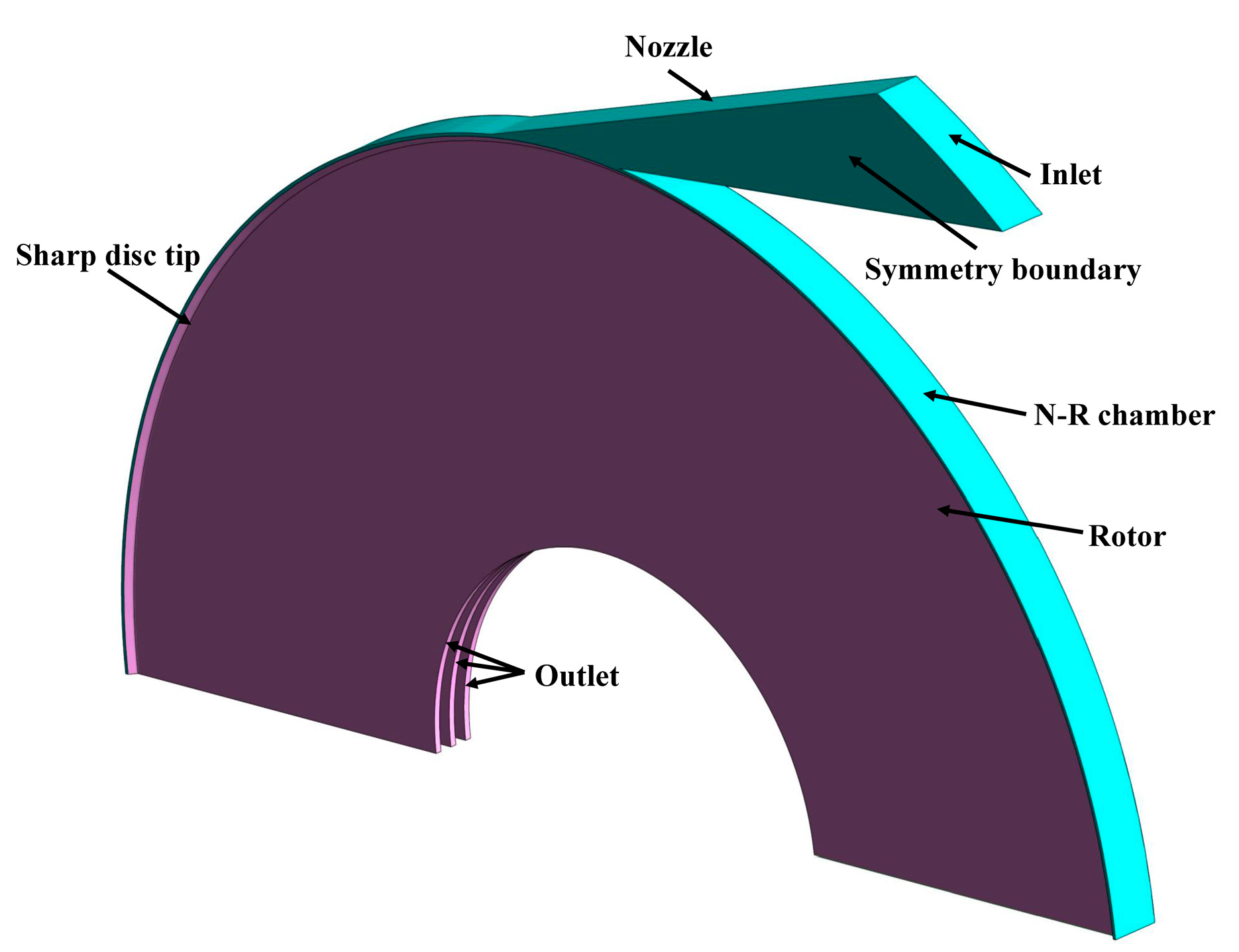
2.1. Geometry Model and Boundary Conditions

In this paper, several models of the two kinds of multichannel Tesla turbines (OTO turbine and OTM turbine) with different disc tip geometries were simulated numerically to investigate how the disc tips influence their aerodynamic performance. The detailed geometrical parameters of the disc tips for each turbine model are given in Table 1, and the cross-section maps of several kinds of disc tips are shown in Figure 4.
The disc tips in this paper consist of the blunt tip and three kinds of sharp tips, including the triangular tip, circular tip and elliptic tip, which are common and easy to manufacture. In the elliptic tip, one of the major axis and minor axis of elliptic is in the axial direction, its ending points are on the disc walls and its distance is disc thickness. The other is in the radial direction, its distance is twice of sharp height and its ending point is on the disc tip. Actually, the circular tip is a typical elliptic tip. The sharp height h is the radial distance of the sharp tip, shown in Figure 4, and the relative height of all kinds of sharp tips is defined as the ratio of sharp height h to disc thickness t. The higher value of relative height means the sharper disc tip. In Table 1, the model name for each turbine is given as “acronym for turbine type-acronym for disc tip profile-number for relative height”, and different number in model names represents different relative height. With the number increasing from 1, 2 to 3, the relative height of sharp tips goes up from 0.2887, 0.5 to 0.8660.
The other geometrical and operational parameters, which are listed in Table 2, are the same as in [22], and the working fluid adopted is compressed ideal air. The related geometrical parameters are marked in Figure 1. In this paper, two issues are analyzed: one is whether sharp tips will help improve the aerodynamic performance of the two kinds of Tesla turbines (OTO-B, OTO-T-2, OTM-B and OTM-T-2); the other is how the relative height and tip profile influence the aerodynamic performance of the Tesla turbines (OTM-B and OTM-T-1, OTM-T-2, OTM-T-3, OTM-C-2 and OTM-E-3).
Each turbine consists of six disc channels, as shown in Figure 2. Obviously, the turbine model is symmetrical about the rotational axis and the middle plane normal to the shaft. In addition, two nozzles are installed uniformly around the disc tip. Therefore, the calculation domain is reduced to half of the whole turbine in the axial and tangential directions respectively, which is a quarter of the whole turbine and shown in Figure 2 and Figure 3 with red color. The 3-dimensional calculation geometrical region for OTM-T-2 is presented in Figure 5.
In this simulation, the boundary conditions were set as shown in Table 2. In detail, the turbine inlet was set as condition of total pressure and total temperature, and the turbine outlet was given a static pressure. All walls were set as adiabatic and no-slip. The boundary conditions of rotational periodicity interface and the symmetry were set at corresponding surfaces. The frozen rotor interface model was applied to transfer data between the stator and the rotor.

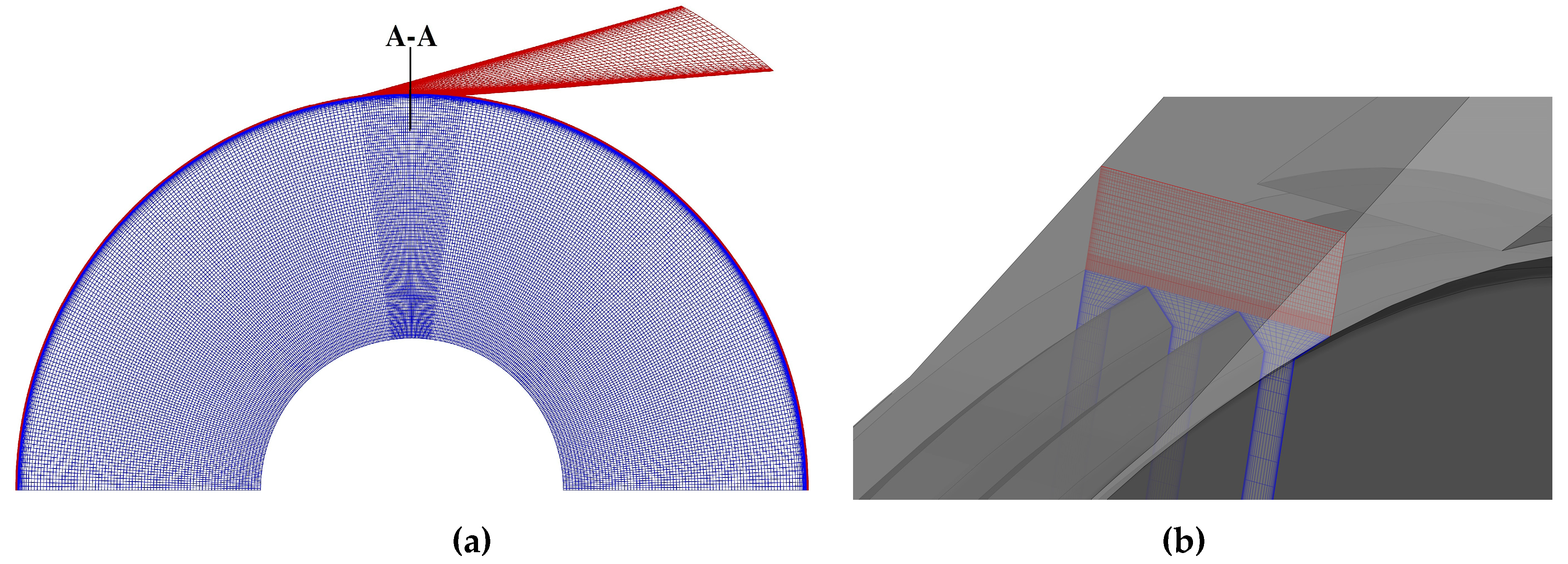
2.2. Numerical Solver and Mesh Sensitivity

Based on the above literature review about Tesla turbines, some researchers investigated the aerodynamic performance experimentally. However, no detailed experimental data about the Tesla turbines are published in public literatures. Therefore, the flow model verification according to experimental data cannot be realized. In the research of plane Poiseuille flow, its critical Reynolds number is about 1000 [30], which is characterized by half disc spacing distance and the mean velocity in Tesla turbines. The minimum Reynolds number is about 1800 among the computational cases in this research. Thus, the flow in the Tesla turbines can be regarded as turbulent, and the RANS model was applied to solve the governing equations for flow in this research. Two detailed methods can be applied to solve RANS equations: one is Reynolds Stress Model (RSM) and the other is eddy viscosity model. RSM closes the governing equations by directly solving the Reynolds stresses consisting of six equations, leading to heavy computation and low convergence. Thus, in this research the Shear Stress Transport (SST) turbulence model based on eddy viscosity hypothesis was adopted, which was also used by other researchers [7,21,27].
In this paper, structured grid in calculation domain, including the stator and rotor, was generated using ANSYS ICEM CFD. To be noted, O topology was applied in the N-R chamber and the rotor to get a high-quality gird. The height of the first grid of solid walls was 0.002 mm, and the expansion ratio of the grid normal to the solid walls was 1.15–1.2, thus to allow y+ less than 2 to meet the requirement of SST turbulence model and get accurate results.
In this research, the flow field in the flow domain was simulated using ANSYS CFX. The CFX solver solves the RANS equations to obtain the solutions for turbulent flow. In addition, the overall solution accuracy is second order due to discretization method for spatial of high-resolution second-order central difference scheme and that for time of second-order backward Euler scheme.
In order to guarantee the grid independence of results, the turbine models with different grid nodes for the one-to-many turbine with blunt tips (OTM-B in Table 1) were simulated. The detailed grid information is shown in Table 3 [23].
The results are given in Table 4, including the isentropic efficiency η , mass flow rate m and power P , and also their relative variation values based on the simulation results of Grid Case 3 [23]. Same with conventional turbines, the isentropic efficiency is defined as the ratio of the actual shaft power to the isentropic power, as follows:
η = P m Δ h isen = T ω m c p T nt [ 1 ( p i / p nt ) ( γ 1 ) / γ ]
where T is the torque, Δ h isen is the isentropic enthalpy drop and ω is the angular speed. cp and γ stand for the specific heat at constant pressure and the adiabatic index, respectively.
Table 4 shows the relative variations of the aerodynamic performance of Grid Case 2 are much less than those of Grid Case 1, and can satisfy the requirements of grid independence. Thus, in this paper, the gird of Grid Case 2 was applied for a turbine with blunt tips. In addition, the grid changes for turbine models with different geometries accordingly.
Figure 6 shows the overall calculation grid and detailed grid at the disc tip for OTM-T-2, and the red grid and the blue grid represent the grids in the stator (nozzle and N-R chamber) and the rotor respectively. For sharp disc tips, the grid number in the axial direction equals to that for the disc channel, that is 29; in the radial direction, the grid expands from the narrower spacing at the N-R chamber to the wider spacing at turbine outlet, and the grid number is 7–11, which increases with relative height of the disc sharp tips. To be noted, the other models with different disc tips have the same grid distributions of the disc tips, and the grid number changes with disc tip geometry.

3. Results and Discussion

In this paper, eight turbine models with different disc tips have been simulated for two kinds of Tesla turbines at different rotational speeds to investigate how the disc tip geometry influences their aerodynamic performance and flow characteristics.

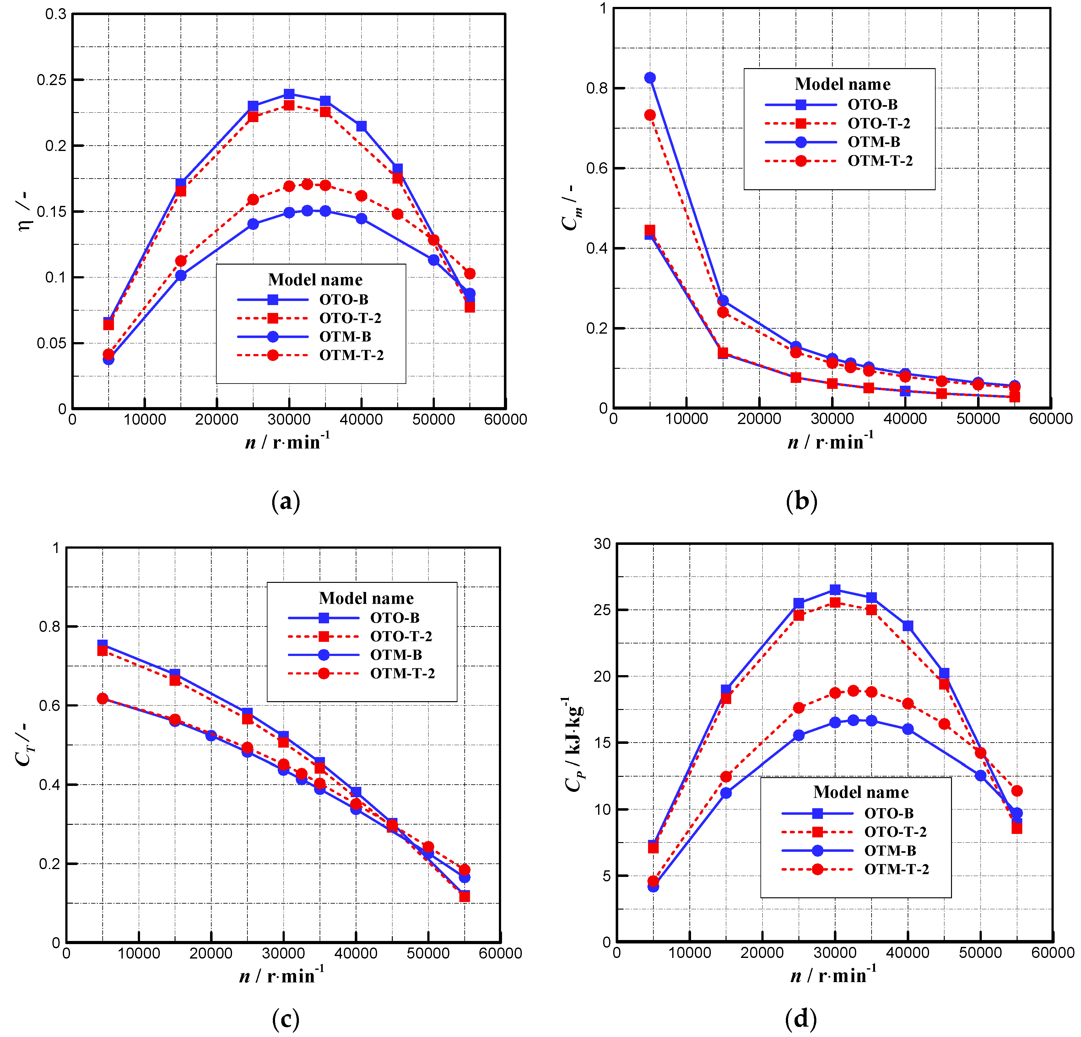
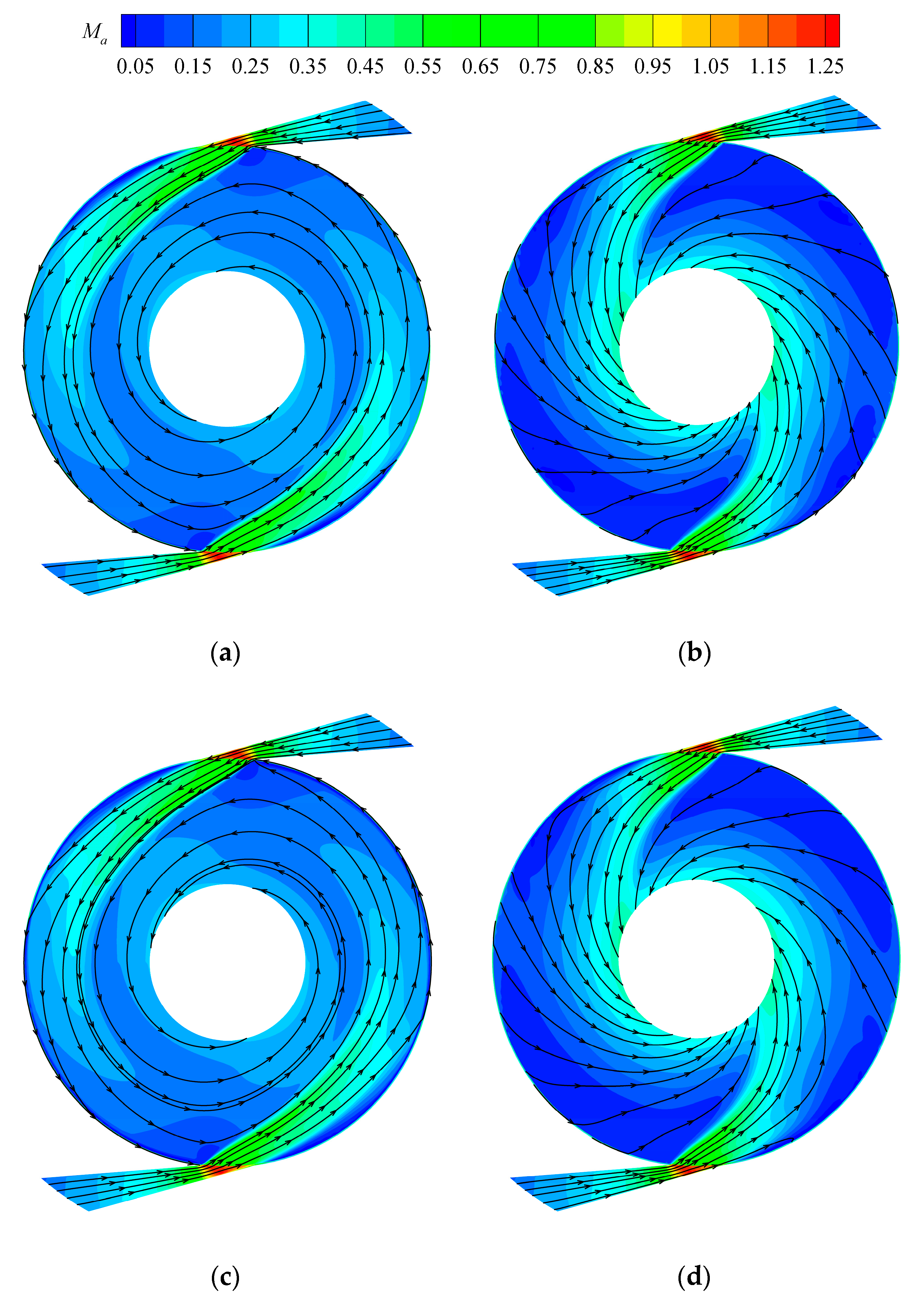
3.1. Comparison of the Influence of Sharp Tips and Blunt Tips on Two Kinds of Tesla Turbines

In order to verify whether sharp disc tips will help enhance the aerodynamic performance of both the OTO turbine and OTM turbine, the two kinds of turbines with blunt tips and sharp tips were simulated numerically at different rotational speeds (OTO-B, OTO-T-2, OTM-B and OTM-T-2). The relative height and tip profile of the two turbines with sharp tips are the same. Figure 7 shows the aerodynamic performance versus the rotational speed for the four turbine models, including the isentropic efficiency, the flow coefficient, the torque coefficient and the specific power. The flow coefficient C m is defined as:
C m = v o , d ω r o , d × 10 3 = m 2 π ρ o , d ω b r o , d 2 × 10 9
where v o , d and ω r o , d represent the average radial velocity and the disc rotational linear velocity at the disc outer edge, respectively.
The torque coefficient C T is calculated using the following equation:
C T = T m u o , d r o , d × 10 3
where u o , d is the average tangential velocity at disc outer edge.
Finally, the specific power C P equals the power divided by the mass flow rate, as follows:
C P = P m × 10 3
As shown in Figure 7, for each turbine model, the isentropic efficiency increases first and then decreases with increasing rotational speed, that is, an optimal rotational speed exists to make the turbine obtain the highest isentropic efficiency, which is 30,000 r/min and 32,500 r/min for the OTO turbine and OTM turbine, respectively. In addition, the isentropic efficiency of the OTM turbine is much lower than that of the OTO turbine, and changes a little more slowly as the rotational speed goes up. The flow and torque coefficients both drop with increasing rotational speed. The variation rule of the specific power versus rotational speed is the same as that of the isentropic efficiency, due to the same isentropic enthalpy drop across each turbine at any rotational speed.
For the OTO turbine, the isentropic efficiency of the turbine with sharp tips (OTO-T-2) is a little less than that with blunt tips (OTO-B), and in detail it decreases from 23.92% to 23.06% at 30,000 r/min (decreases by a relative value of 3.6%); while for the OTM turbine, the turbine efficiency increases significantly when blunt dips (OTM-B) are replaced by sharp tips (OTM-T-2), and it relatively increases by about 13.5% at almost all rotational speeds. It can be concluded that sharp disc tips enhance the isentropic efficiency of the OTM turbine, but decrease that of the OTO turbine. For both the OTO turbine and the OTM turbine, the rules of aerodynamic performance variation with rotational speed for models with sharp tips are the same as those for models with blunt tips, and the optimal values of the rotational speed are also unchanged.
When sharp tips replace blunt tips, the torque coefficient and specific power of the OTM turbine increase and those of the OTO turbine decrease. The flow coefficient of the OTM turbine decreases; that of the OTO turbine remains unchanged. To reveal the mechanism of the influence of different disc tips on the aerodynamic performance of the OTO turbine, Figure 8 gives the streamlines and Mach number distributions on the middle of DC1 and DC3 for the OTO turbine models at 30,000 r/min. The locations of the three disc channels are marked in Figure 2 and Figure 3. DC1 and DC2 include two rotating disc walls, while DC3 only has one rotating disc wall and one stationary casing wall. In the authors’ previous study, the flow fields in DC1 and DC2 were exactly the same, and totally different from than in DC3 for both the OTO turbine and the OTM turbine [22]. Therefore, only the flow fields in DC1 and DC3 are discussed in the following analysis.
Comparing Figure 8a and Figure 8c, the flow fields on the middle of DC1 for OTO-B and OTO-T-2 are almost the same. In detail, the area of high Mach number close to the rotor inlet where the air just flows out of the nozzle into DC1 for OTO-T-2 is less than that for OTO-B, leading to less momentum exchange; the low flow velocity appears at most of the rotor periphery for OTO-T-2, resulting in more energy loss. Comparing Figure 8b and Figure 8d, the flow fields in DC3 for OTO-B and OTO-T-2 are also similar. All the above leads to a slight drop in flow efficiency and torque when disc blunt tips are replaced by disc sharp tips.
Figure 9 shows the streamlines and relative tangential velocity distributions on four radial cross-sections of different circumferential angles for the one-to-one turbine OTO-B and OTO-T-2 at 30,000 r/min. The locations of angles are shown in Figure 1, and two nozzles are installed at the location of 0° and 180°. The figure comprises both the N-R chamber and the disc channels. In addition, the geometry in this figure doubles in the axial direction to present the flow fields more clearly. In each subfigure the above figure shows the flow field of the turbine with sharp tips and the below figure indicates that with blunt tips. What should be noted is that the positive relative tangential velocity in this figure represents its direction is the same as the rotational direction, and the turbines transfer the thermal energy of working fluid to mechanical energy; otherwise the mechanical energy is absorbed by the working fluid. Most negative relative tangential velocity appears near the rotor casing wall or a small part of disc channel inlet, as shown in Figure 9.
It can be seen that the flow fields at most region of each cross-section for OTO-B and OTO-T-2 are quite similar, but some obvious differences exist. Some vortices occur at the inlet of each disc channel for OTO-T-2, which deteriorates the air flow and causes energy loss. The relative tangential velocity at the regions close to the rotor inlet on the cross-sections of 45°, 90° and 135° for OTO-T-2 is a little lower than that for OTO-T-2, resulting in less momentum exchange. In summary, all these flow phenomena lead to lower isentropic efficiency for OTO-T-2 than that for OTO-B.
To sum up, in OTO-T-2 the air injects into the rotor more difficultly than that in OTO-B due to some vortices at the disc channel inlet. In order to analyze in depth, Figure 10 shows the vectors and relative tangential velocity distributions on the radial cross-section of 0° for OTO-B and OTO-T-2, where the nozzles are installed and most air flows into the rotor. To display the flow field clearly, the section has also been stretched twice in the axial direction. The velocity in the stator indicates absolute velocity and in the rotor it presents relative velocity. As shown in Figure 10a, most air in OTO-B flows into the rotor directly with few vortices in the N-R chamber, while in OTO-T-2, counter-rotating vortex pairs occur at the N-R chamber and two sides of the sharp tip region (marked with red curves), resulting from larger expansion area, shown in Figure 10b. Comparisons of two flow fields show that for the OTO turbine, sharp tips generate a larger N-R chamber, which allows more air to expand and stay there instead of directly flowing into the rotor and thus causing an extra energy loss.
To reveal the vortex structure and distribution in the disc tip and N-R chamber, the Q criterion which was put forward by Hunt et al. in 1988 [31] is one of the best options, and was applied to reveal and analyze turbulence structure in kinds of flow fields [32,33]. It reflects the motion of rotation quantitatively and thus describes the vortex structure. Q criterion in the three dimensional coordinate system can be expressed as following equation:
Q = ( u j x j u k x k u j x k u k x j ) + ( u i x i u j x j u i x j u j x i ) + ( u k x k u i x i u i x k u k x i )
Figure 11 shows the distributions of the iso-surface of Q at the disc tip, and Q = 4 × 10 8 for OTO-B and OTO-T-2. The red planes in this figure stand for different radial sections, and the blue surfaces are the iso-surfaces of Q. The region formed by blue surfaces can also be called vortex core region. Obviously, compared with OTO-B, the vortex core regions at the nozzle outlet in OTO-T-2 are much larger, and the vortices in the N-R chamber and disc tips develop along the rotational direction (shown with a black arrow) and finally into the rotor inlet. Thus they block the flow channel, generate energy loss and decrease flow efficiency. The vortices at the N-R chamber and rotor inlet can also be observed in Figure 9.
Figure 12 shows the streamlines and Mach number distributions on the middle of DC1 and DC3 for OTM-B and OTM-T-2 at 30,000 r/min. Comparing Figure 12a and Figure 12c, the flow field in DC1 for the OTM turbine with sharp disc tips (OTM-T-2) varies a lot from that with blunt disc tips (OTM-B). Firstly, the flow angle in DC1 (relative to the tangential direction) for OTM-T-2 is much less than that for OTM-B, leading to higher relative tangential velocity and more momentum exchange. Secondly, compared to OTM-B, the vortices at the rotor inlet on two sides of the nozzle outlet for OTM-T-2 decrease a lot, causing less energy loss in the rotor. Finally, the region of low Mach number in the whole DC1 for OTM-T-2 reduces significantly. All these lead to more momentum exchange and less energy loss in DC1 for OTM-T-2. Comparing Figure 12b and Figure 12d, the flow field in DC3 for OTM-T-2 changes a lot from that for OTM-B. The vortices at the rotor inlet for OTM-T-2 decrease remarkably, and the region of low Mach number in DC3 also reduces. Thus, the energy loss in DC3 for OTM-T-2 is much less than that for OTM-B.
In general, compared with the OTM turbine with blunt tips, the flow status in DC1 and DC3 for the turbine with sharp tips improves a lot, especially in DC1, due to a decrease in vortices, low flow velocity area and flow angle. Thus, it leads to higher isentropic efficiency and torque for the OTM turbine with sharp disc tips.
To be noted, different from the OTO turbine, the Mach number increases urgently at the rotor inlet directly facing to the nozzle outlet for the OTM turbine, due to the flow area reduces sharply when the air flows through the N-R chamber to the disc channels. Compared with OTM-B, the sudden increase in Mach number for OTM-T-2 decreases, which is because the reduction rate of the flow area slows down for OTM-T-2.
The streamlines and relative tangential velocity distributions on four radial cross-sections of different circumferential angles are shown in Figure 13 for the one-to-many turbine OTM-B and OTM-T-2 at 30,000 r/min. Compared with OTM-B, the flow field on the radial cross-section of 0° for OTM-T-2 is almost the same, however, the relative tangential velocity for OTM-T-2 is a little higher at the region near the rotor inlet where the working fluid has more advantages to exchange momentum due to greater moment arm. The vortices on the radial section of 45° disappear in OTM-T-2, and the relative tangential velocity near the rotor inlet is much higher. Although the relative tangential velocity on the cross-section of 45° near the rotor outlet for OTM-B is much higher than that for OTM-T-2, its contribution to momentum exchange is much less and it causes higher leaving-velocity energy loss. On the radial cross-sections of 90° and 135°, the relative tangential velocity near the rotor inlet for OTM-T-2 is a little higher than that for OTM-B, leading to more torque. To be noted, the flow condition on the radial cross-section of 45° improves much more significantly than that on other cross-sections.
The vectors and relative tangential velocity distributions on the radial cross-section of 0° for the OTM turbine models at 30,000 r/min are shown in Figure 14. Obviously, compared with OTM-B, the flow velocity at the nozzle outlet for OTM-T-2 is a little higher, leading to a higher relative tangential velocity at the inlet of disc channels. In OTM-B, the air at the nozzle outlet bends towards disc channels (marked with red curves), and some vortices appear at the outer region of disc walls and finally disappear after a short radial distance. In OTM-T-2, the flow area goes down continuously and slowly from the N-R chamber to the disc channels, and thus the air velocity changes gently with no sudden variation. To sum up, the flow process in OTM-T-2 is more smooth than that in OTM-B, leading to less energy loss.
Similarly, the vortices at the nozzle outlet in OTM-T-2 are fewer than that in OTM-B, which can be observed in Figure 15, and it presents the iso-surface of Q for the one-to-many turbine models, Q = 4 × 10 8 . More vortices can be found at the whole N-R chamber in OTM-B, blocking the inlet of disc channels and decreasing flow velocity. While some vortices appear at the disc sharp tip region in OTM-T-2, and most of them are on the disc tip walls with fewer effects on flow velocity. Thus, compared with OTM-B, the air in OTM-T-2 flows more smoothly into the rotor, and leads to less energy loss. All phenomena can also be found in Figure 13.
Based on all the above discussion, for the one-to-one turbine, the isentropic efficiency decreases a little as the blunt disc tips are replaced by the sharp disc tips, while for the one-to-many turbine that increases significantly. Therefore, in the design of a multichannel Tesla turbine, a one-to-one turbine with blunt disc tips or a one-to-many turbine with sharp disc tips is suggested.

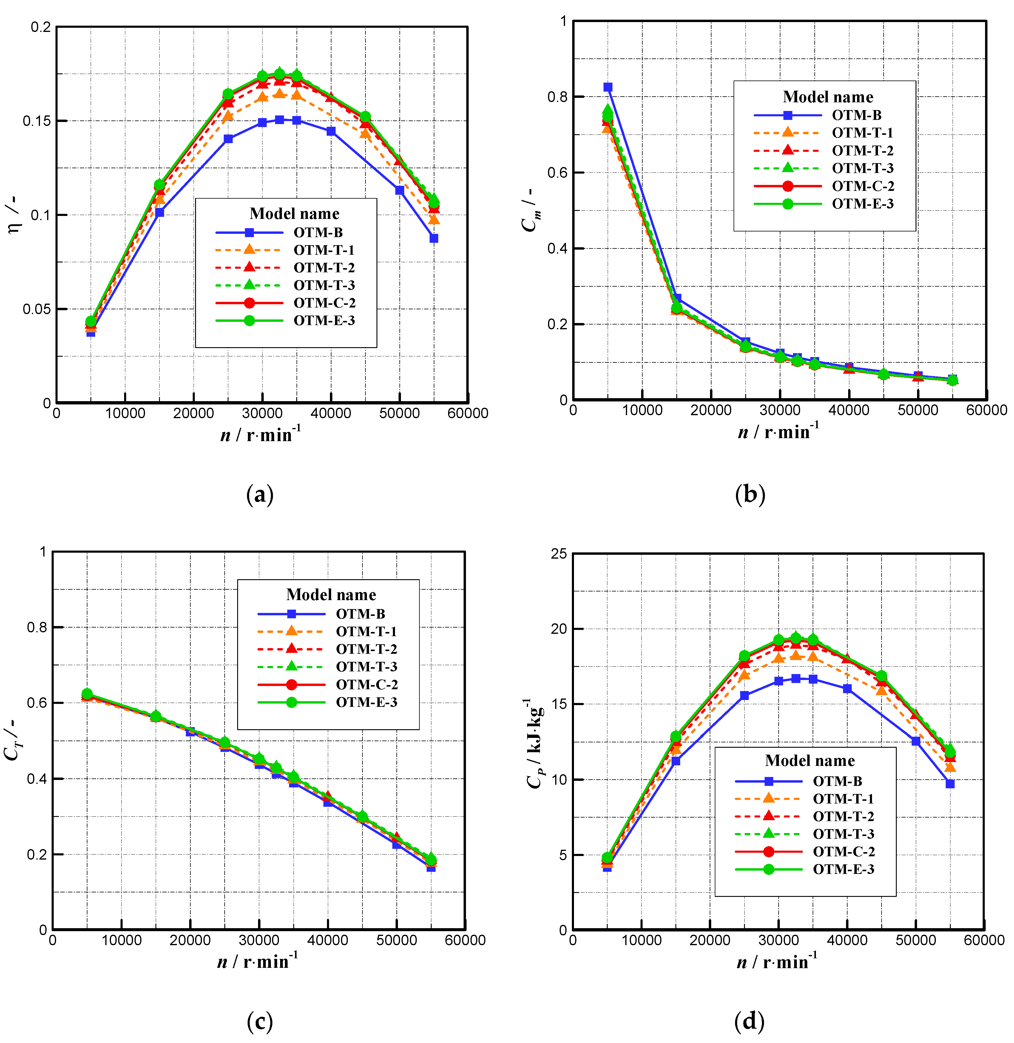
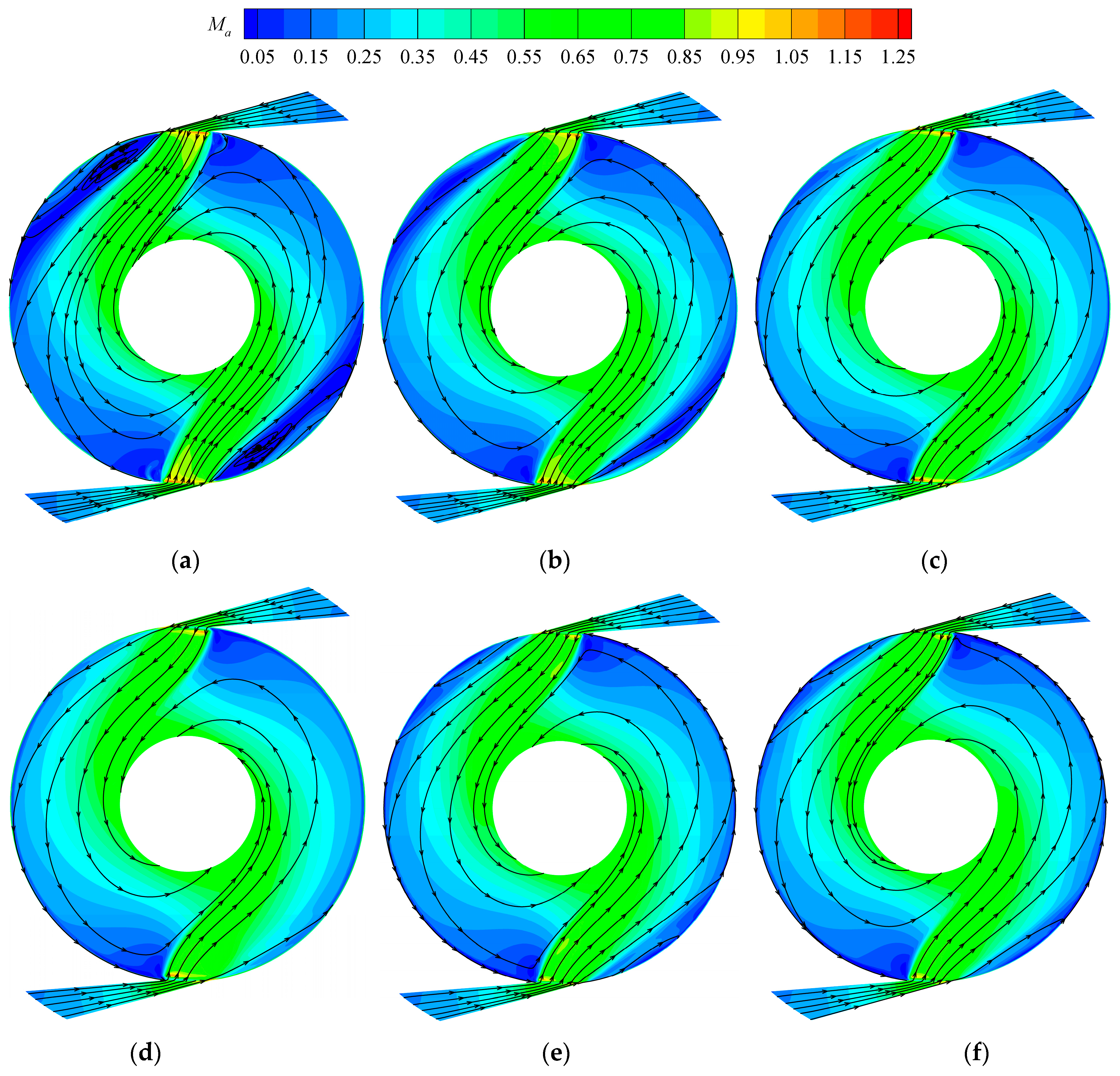
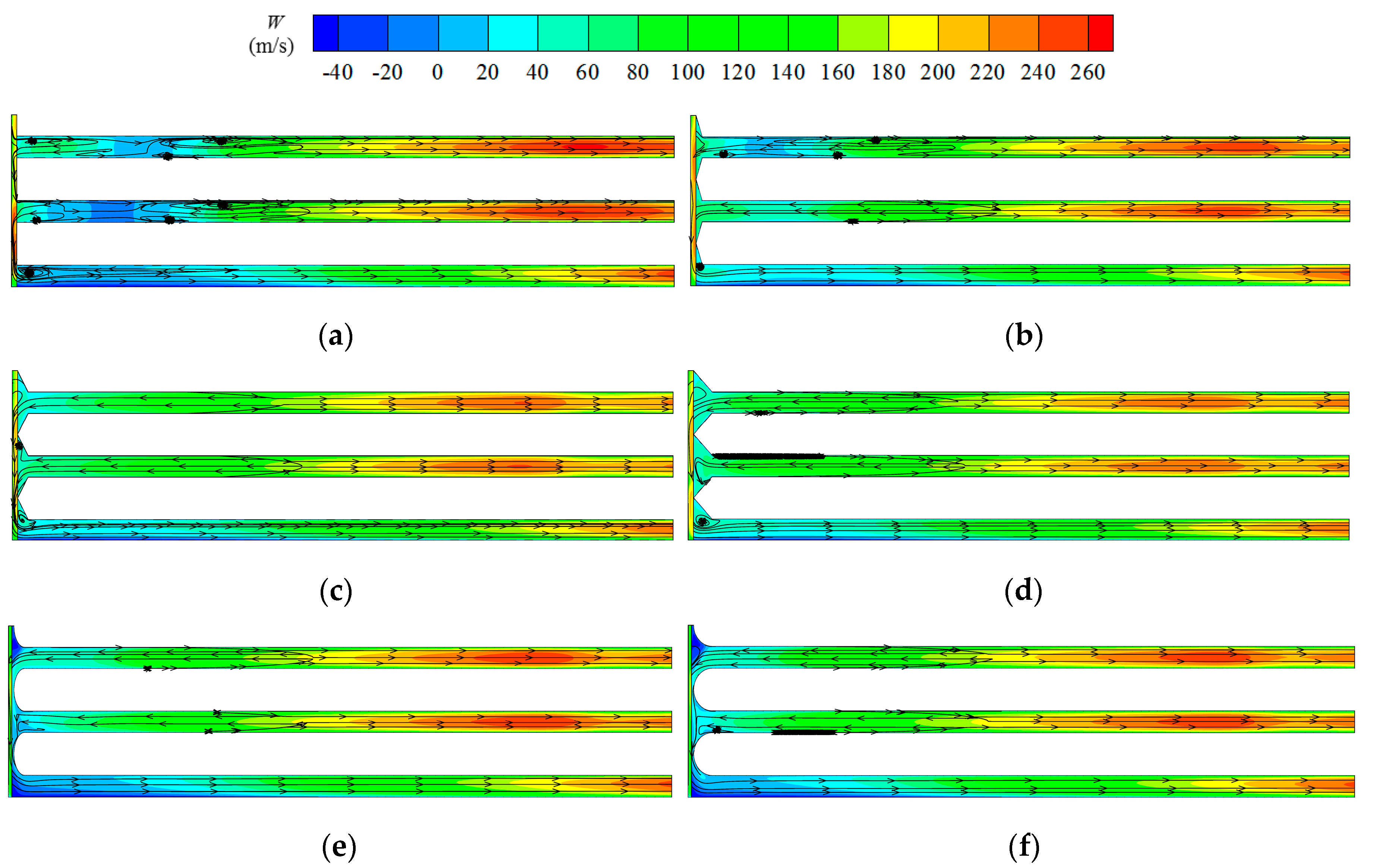
3.2. Influence of Relative Height and Sharp Tip Profile on the One-to-Many Turbine

Sharp disc tips improve the flow status and aerodynamic performance of the OTM turbine, while worsen those of the OTO turbine. In this section, several OTM turbine models with different disc sharp tips were simulated numerically to investigate the influence of relative height and sharp tip profile on the flow characteristics and aerodynamic performance.
Figure 16 shows the aerodynamic performance versus rotational speed for the OTM turbine models with different disc tips. The isentropic efficiency variation rule with rotational speed for each turbine with sharp disc tips is the same as that for the turbine with blunt tips, and the optimal rotational speed for each turbine model is the same, 32,500 r/min. The variation rules of other aerodynamic performance parameters for each turbine model with disc sharp tips are also the same as those for the turbine with blunt tips. That is, relative height and sharp tip profile don’t change the variation rules of the aerodynamic performance, and only change their values.
For the turbine models with triangular tips, the isentropic efficiency increases with relative height (from OTM-T-1, OTM-T-2 to OTM-T-3), and higher than that of the turbine with blunt tips. It increases more slowly with increasing relative height. The variation rate of the isentropic efficiency decreases from 0.033 to 0.013 at 30,000 r/min, which is defined as variation value of efficiency divided by that of relative height. It can be predicted that the isentropic efficiency would not go up when the relative height increases to a certain value.
The isentropic efficiency for OTM-C-2 is a little higher than that for OTM-C-2, and that for OTM-T-3 and OTM-E-3 is almost the same. The efficiency difference between turbines with different disc profiles decreases with increasing relative height. From the view of aerodynamic performance, the circular or elliptic tip is better than the triangular tip when the relative height is lower, and as relative height increases to a certain value (0.8660 in this research) the two tip profiles have a same better performance. It can be predicted that when the relative height continues to increase, the triangular tip will behave better. To be noted, all kinds of tip profiles all follow the rule that the isentropic efficiency increases with relative height and its increment rate slows down. In general, the determination of tip profile depends on aerodynamic performance (mainly affected by relative height) and manufacturing difficulty.
The flow coefficients for the turbine models with different sharp tips are almost the same, and it increases slightly with relative height. However, that for each turbine model with sharp tips is a little less than that with blunt tips. For all the turbine models with sharp tips, the mass flow rate is higher than that with blunt tips, while the density at the rotor inlet is much higher, leading to a lower flow coefficient. With an increase in relative height, the mass flow rate increases and the density at the rotor inlet decreases, resulting in an increase in flow coefficient. The torque coefficients for all the turbine models with sharp tips are almost the same, and a little higher than that with blunt tips at most rotational speeds.
To be noted, the isentropic efficiency for the OTM turbine gets higher with increasing relative height, and its rise rate reduces as relative height goes up. In addition, the deformation of the discs due to mechanical stress increases when the relative height increases to a large value, based on the theory of structural mechanics. Therefore, in the design of a one-to-many turbine, the influence of relative height on the aerodynamic performance and the mechanical deformation should be taken into consideration simultaneously.
Figure 17 shows the streamlines and Mach number distributions on the middle of DC1 for the one-to-many turbine models with different sharp tips at 30,000 r/min. It can be seen that the flow status becomes better for all the turbine models with sharp tips than that with blunt tips, in detail a decrease in flow angle in disc channels and area of low Mach number and vortex. And with increasing relative height the improvement of flow status becomes more significant, displayed in Figure 17b–d. The flow fields for OTM-T-2 and OTM-C-2, shown in Figure 17c,e, are similar, and in detail the Ma number at the middle radius region below nozzle is higher for OTM-C-2, leading to a little higher turbine efficiency. The flow fields for OTM-T-3 and OTM-E-3 are similar, leading to similar aerodynamic performance. In detail, the regions of low Mach number at the rotor inlet for OTM-E-3 are slightly larger than that for OTM-T-3. All these flow phenomena can explain the above influence on aerodynamic performance. As mentioned previously, the flow status getting better in DC3 for the one-to-many turbine with sharp tips is the same as that in DC1, therefore the flow fields in DC3 are not given here.
Based on the discussion in the previous section, the flow status for the one-to-many turbine with sharp tips improves more significantly on the radial cross-section of 45°, and that on other sections improves similarly. Therefore, only the streamlines and relative tangential velocity distributions on the radial cross-section of 45° for different turbine models at 30,000 r/min are given in Figure 18. Obviously, the vortices decrease much more for the turbine model with higher relative height, and the relative tangential velocity near the rotor inlet increases more, leading to more momentum exchange and higher flow efficiency. For the turbine model with circular tip or elliptic tip, the relative tangential velocity close to rotor inlet is a little less than that for the turbine with triangular tip.
Based on the above discussion, the relative variation of isentropic efficiency for each turbine model based on each kind turbine with blunt tips at 30,000 r/min are summarized in Figure 19, which helps understand the effects of disc tips apparently. Obviously, one-to-one turbine with blunt tips or one-to-many turbine with sharp tips with larger relative height is suggested for designing a multichannel Tesla turbine.

4. Results

In this paper, the flow fields within two kinds of multichannel Tesla turbines (one-to-one turbine and one-to-many turbine) with blunt disc tips and sharp disc tips have been simulated to research whether the sharp tips contribute to improve their aerodynamic performance and how the significant parameters of sharp tips, namely relative height and sharp tip profile, influence the isentropic efficiency. The major conclusions are as follows:
(1)
Compared to the turbine with blunt disc tips, the isentropic efficiency of the one-to-one turbine with sharp disc tips reduces a little, while that of the one-to-many turbine with sharp disc tips increases remarkably. It decreases by 3.6% for the one-to-one turbine and increases by 13.5% for the one-to-many turbine at 30,000 r/min. The flow coefficient of the one-to-one turbine with sharp tips is almost the same, while that of the one-to-many turbine with sharp tips is a little lower. For all rotational speeds, it varies less than 0.02% for the one-to-one turbine, and decreases about 7–10% for the one-to-many turbine.
(2)
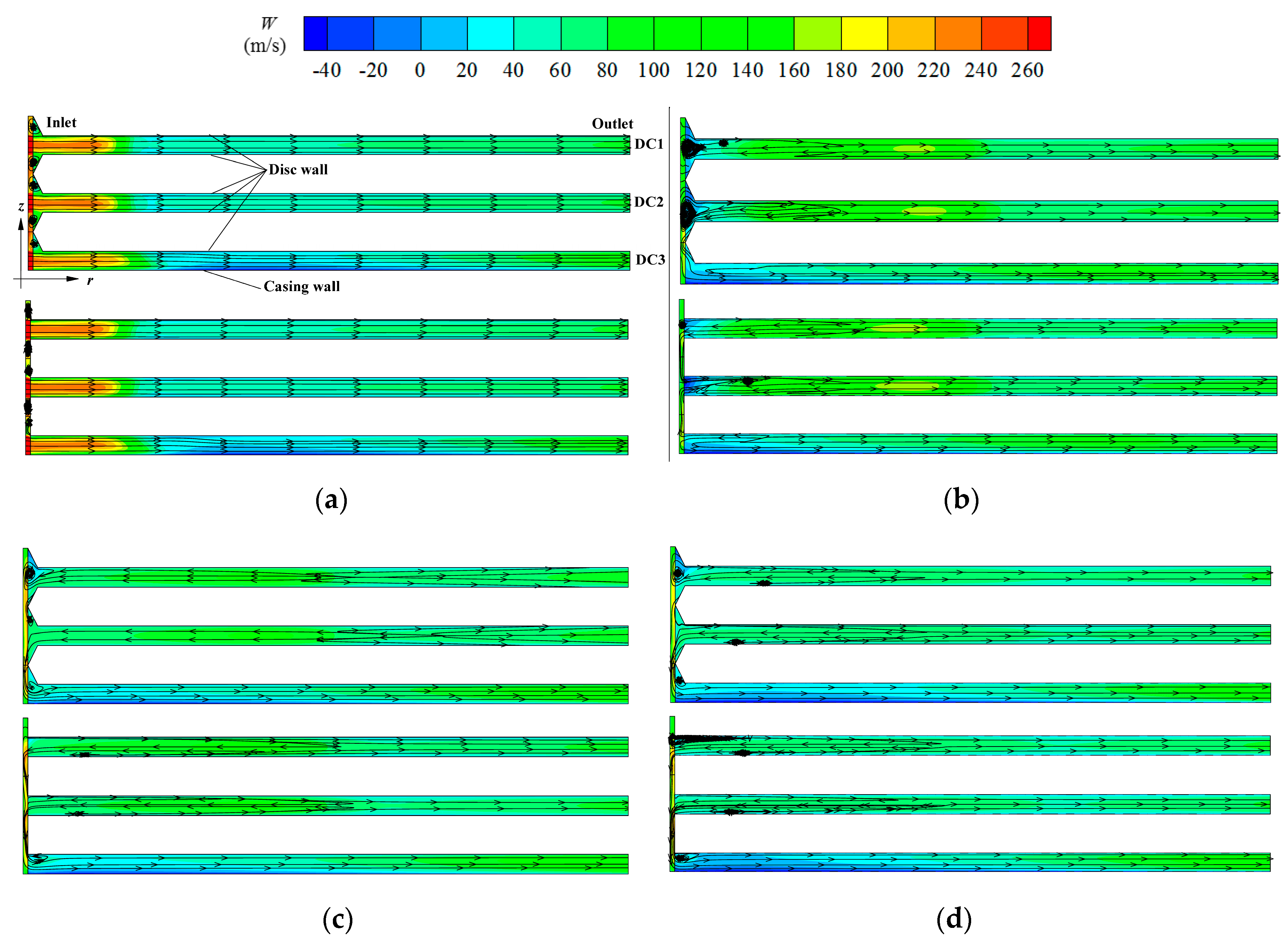
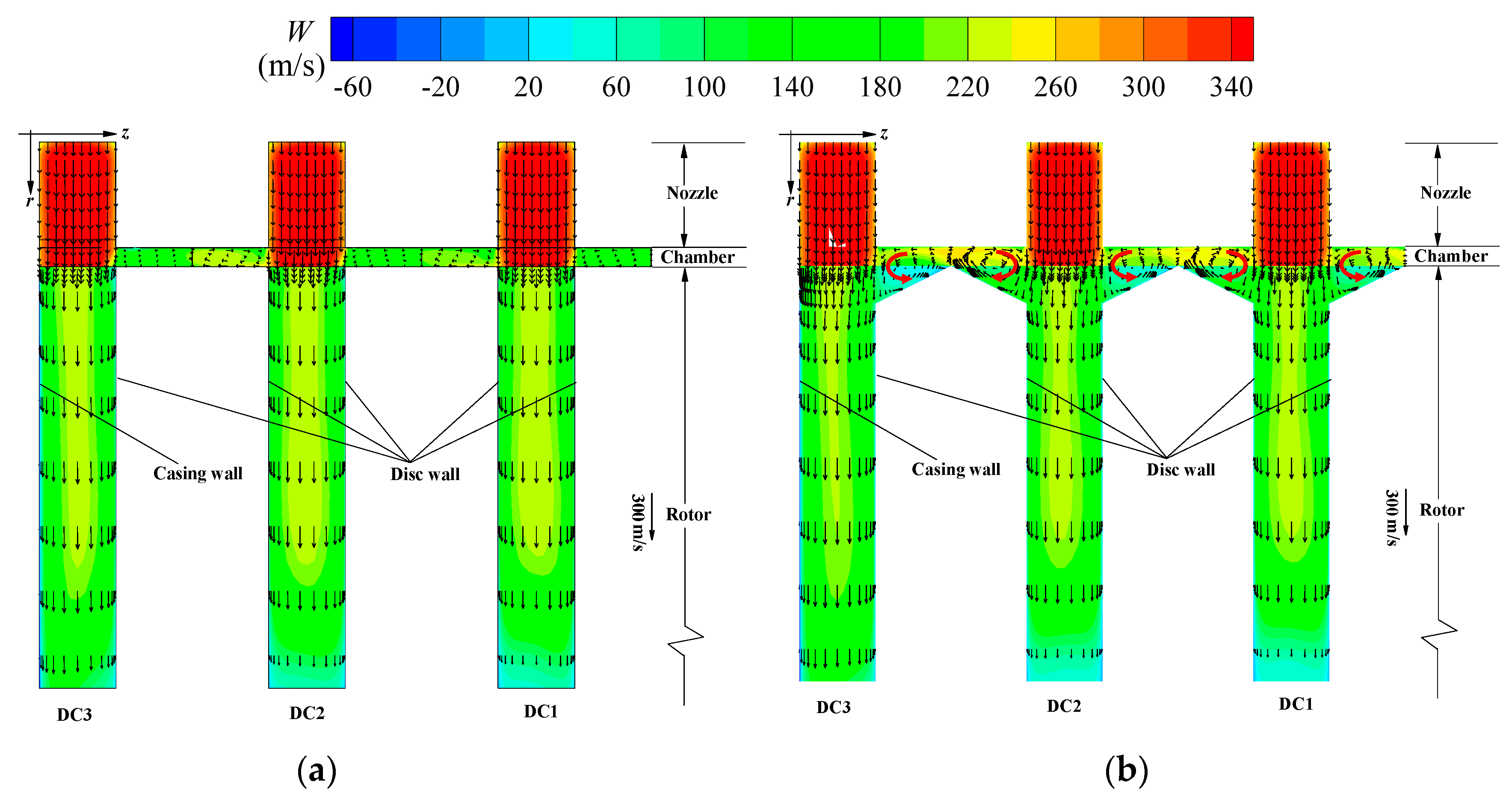
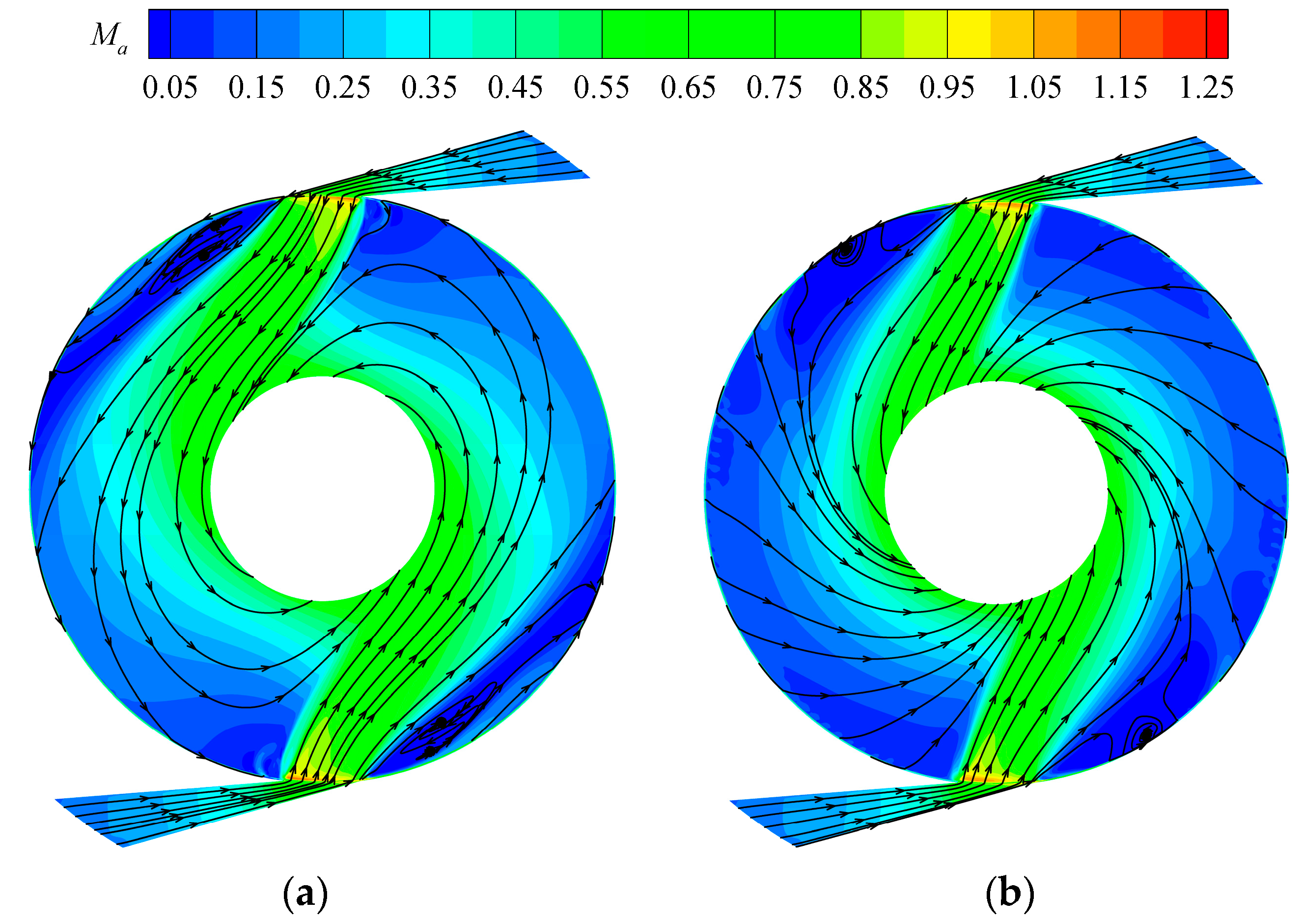
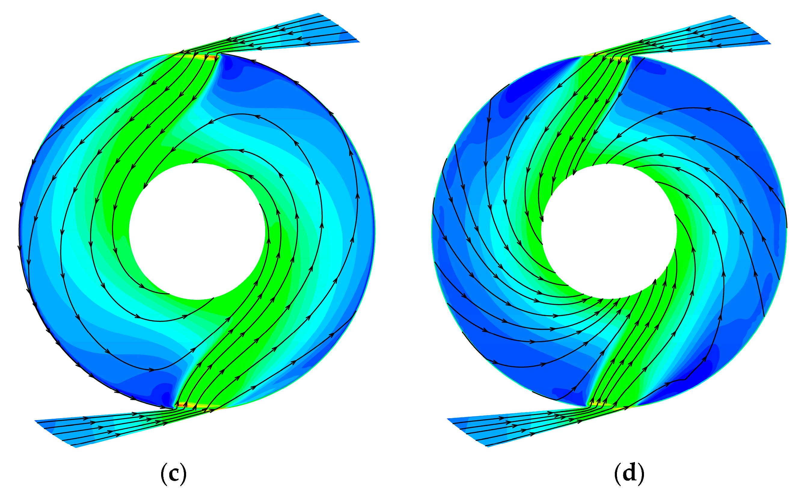
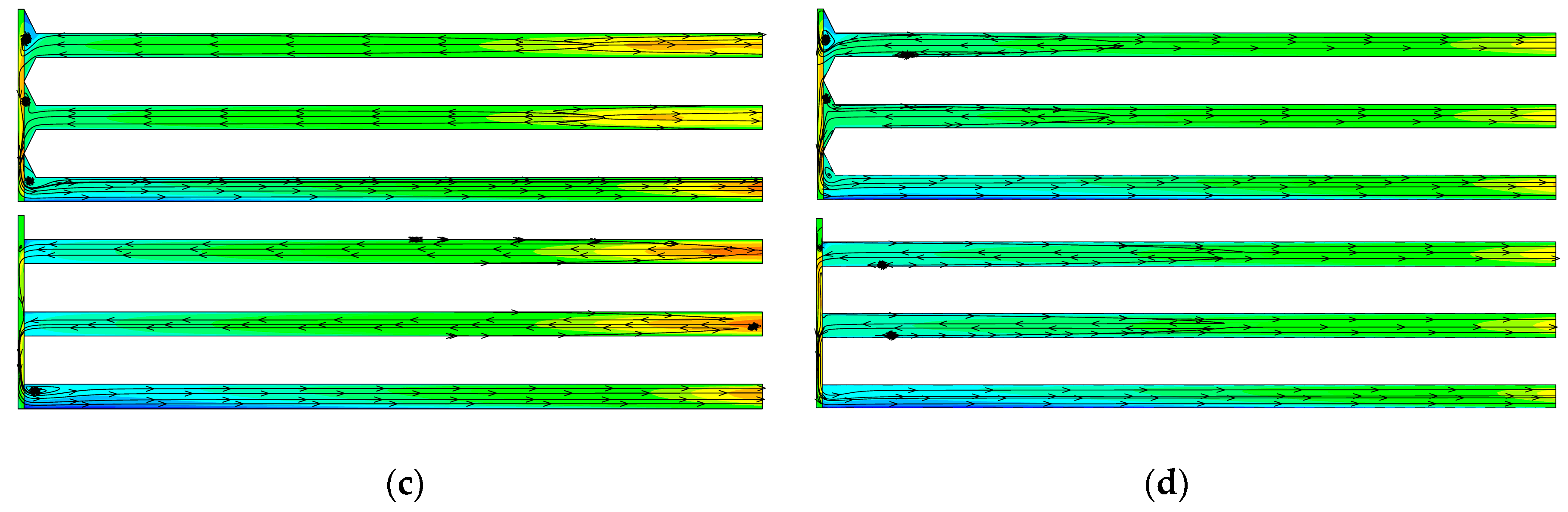
Compared to the one-to-one turbine with blunt tips, the flow field is almost the same for the turbine with sharp tips; the relative tangential velocity gradient on disc walls is a little less and some vortices exist at the inlet of the disc channels, leading to less momentum exchange and more energy loss for the turbine with sharp tips. Compared to the one-to-many turbine with blunt tips, the flow angle relative to the tangential direction in the disc channels of the turbine with sharp tips is much less, leading to higher relative tangential velocity and more momentum exchange; the area of low Mach number and vortex reduces, leading to less energy loss.
(3)
For the one-to-many turbine, the isentropic efficiency of the turbine with sharp tips increases with relative height, which must be higher than that with blunt tips, and its relative increase value is 8.9%–16.6% at 30,000 r/min. The increment rate of the isentropic efficiency with sharp tips slows down with increasing relative height, and it decreases from 0.033 to 0.013 at 30,000 r/min as the relative height increases from 0.2887, 0.5 to 0.8660. In addition, the circular or elliptic tips perform better at lower relative height, and a triangular tip behaves better at higher relative height.
(4)
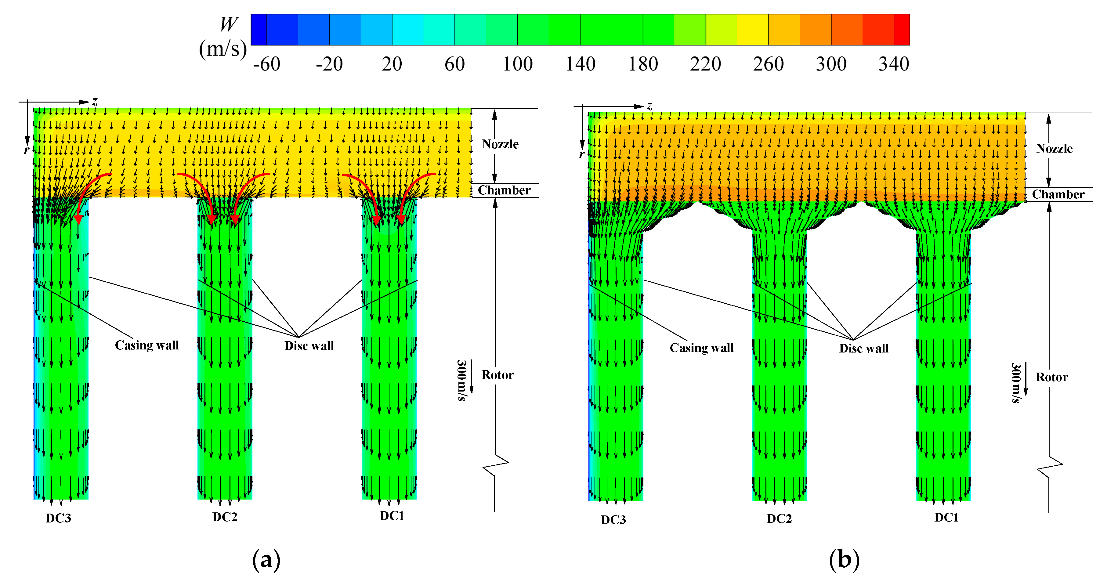
Compared to the one-to-many turbine with blunt tips, the improvement of flow field within the turbine with sharp tips becomes much better with increasing relative height, and in detail, the flow angle in the disc channels decreases and the area of low flow velocity reduces, leading to an increase in isentropic efficiency.

Author Contributions

Conceptualization, W.Q. and Q.D.; Methodology, W.Q. and Q.D.; Investigation, W.Q. and Z.C.; Data Curation, W.Q. and L.H.; Writing—Original Draft Preparation, W.Q.; Writing—Review and Editing, Q.D., Q.Y. and Z.F.; Visualization, Z.C. and L.H.; Supervision, Q.Y. and Z.F.

Funding

This research was funded by National Natural Science Foundation of China, grant number 51376143.

Conflicts of Interest

The authors declare no conflict of interest.

Nomenclature

bdisc spacing distance, mm
cradial clearance of nozzle-rotor chamber, mm
cpspecific heat at constant pressure, J/kg·K
Cmflow coefficient
CPspecific power, kJ/kg
CTtorque coefficient
ddiameter, mm
hsharp height, mm
h/trelative height
mmass flow rate, kg/s
MaMach number
nrotational speed of the rotor, r/min
Nnumber
p nt / p i ratio of total pressure at the nozzle inlet to pressure at the turbine outlet
Ppower, W
QQ criterion
rradial coordinate or radius, mm
tdisc thickness, mm
Ttorque, N·m
Tnttotal temperature at the nozzle inlet, K
uaverage tangential velocity, m/s
u i , u j , u k three velocity components in x i ,   x j ,   x k directions, m/s
vaverage radial velocity, m/s
Wrelative tangential velocity, m/s
x i , x j , x k Cartesian coordinate axis, m
zaxial coordinate, mm
α nozzle exit geometrical angle (relative to the tangential direction), °
γ adiabatic index
δ relative variation of parameters
Δ h isen isentropic enthalpy drop of the whole turbine, J/kg
η isentropic efficiency
θ circumferential coordinate, rad
ρ density, kg/m3
ω rotational angular speed, rad/s
Subscripts
ddisc
dcdisc channel
iinner
nnozzle
oouter

References

  1. Gerendas, M.; Pfister, R. Development of a very small aero-engine. In Proceedings of the ASME Turbo Expo 2000, Munich, Germany, 8–11 May 2000. [Google Scholar]
  2. Epstein, A.H. Millimeter-scale, MEMS gas turbine engines. J. Eng. Gas Turbines Power 2015, 126, 205–226. [Google Scholar] [CrossRef]
  3. Fu, L.; Feng, Z.P.; Li, G.J. Experimental investigation on overall performance of a millimeter-scale radial turbine for micro gas turbine. Energy 2017, 134, 1–9. [Google Scholar] [CrossRef]
  4. Fu, L.; Feng, Z.P.; Li, G.J. Investigation on design flow of a millimeter-scale radial turbine for micro gas turbine. Microsyt. Technol. 2018, 24, 2333–2347. [Google Scholar] [CrossRef]
  5. Fu, L.; Feng, Z.P.; Li, G.J. Discussions on problem analysis and solutions of a micro turbine test. Microsyt. Technol. 2018, 24, 1433–1442. [Google Scholar] [CrossRef]
  6. Isomura, K.; Murayama, M.; Teramoto, S.; Hikichi, K.; Endo, Y.; Togo, S.; Tanaka, S. Experiment verification of the feasibility of a 100 W class micro-scale gas turbine at an impeller diameter of 10 mm. J. Micromech. Microeng. 2006, 16, s254–s261. [Google Scholar] [CrossRef]
  7. Lampart, P.; Kosowski, K.; Piwowarski, M.; Jedrzejewski, L. Design analysis of Tesla microturbine operating on a low-boiling medium. Pol. Marit. Res. 2009, 16, 28–33. [Google Scholar]
  8. Tesla, N. Turbine. U.S. Patent 1,061,206, 6 May 1913. [Google Scholar]
  9. Lemma, E.; Deam, R.T.; Toncich, D.; Collins, R. Characterisation of a small viscous flow turbine. Exp. Therm. Fluid Sci. 2008, 33, 96–105. [Google Scholar] [CrossRef]
  10. Rice, W. An analytical and experimental investigation of multiple-disk turbines. J. Eng. Power 1965, 87, 29–36. [Google Scholar] [CrossRef]
  11. Beans, E.W. Investigation into the performance characteristics of a friction turbine. J. Spacecr. 1966, 3, 131–134. [Google Scholar] [CrossRef]
  12. Deam, R.T.; Lemma, E.; Mace, B.; Collins, R. On scaling down turbines to millimeter size. J. Eng. Gas Turbines Power 2008, 130, 052301. [Google Scholar] [CrossRef]
  13. Deng, Q.H.; Qi, W.J.; Feng, Z.P. Improvement of a theoretical analysis method for Tesla turbines. In Proceedings of the ASME Turbo Expo 2013, San Antonio, TX, USA, 3–7 June 2013. [Google Scholar]
  14. Guha, A.; Sengupta, S. Similitude and scaling laws for the rotating flow between concentric discs. Proc. Inst. Mech. Part A J. Power Energy 2014, 228, 429–439. [Google Scholar] [CrossRef]
  15. Carey, V.P. Assessment of Tesla turbine performance for small scale Rankine combined heat and power systems. J. Eng. Gas Turbines Power 2010, 132, 122301. [Google Scholar] [CrossRef]
  16. Sengupta, S.; Guha, A. A theory of Tesla disc turbines. Proc. Inst. Mech. Part A J. Power Energy 2012, 226, 650–663. [Google Scholar] [CrossRef]
  17. Guha, A.; Sengupta, S. The fluid dynamics of the rotating flow in a Tesla disc turbine. Eur. J. Mech. B/Fluid 2013, 37, 112–123. [Google Scholar] [CrossRef]
  18. Sengupta, S.; Guha, A. Analytical and computational solutions for three-dimensional flow-field and relative pathlines for the rotating flow in a Tesla disc turbine. Comput. Fluids 2013, 88, 344–353. [Google Scholar] [CrossRef]
  19. Hidema, T.; Okamoto, K.; Teramoto, S.; Nagashima, T. Numerical investigation of inlet effects on Tesla turbine performance. In Proceedings of the AJCPP, Miyazaki, Japan, 4–6 March 2010. [Google Scholar]
  20. Qi, W.J.; Deng, Q.H.; Feng, Z.P.; Yuan, Q. Influence of disc spacing distance on the aerodynamic performance and flow field of Tesla turbines. In Proceedings of the ASME Turbo Expo 2016, Seoul, Korea, 13–17 June 2016. [Google Scholar]
  21. Lampart, P.; Jedrzejewski, L. Investigations of aerodynamics of Tesla bladeless microturbines. J. Theor. Appl. Mech. 2011, 49, 477–499. [Google Scholar]
  22. Qi, W.J.; Deng, Q.H.; Jiang, Y.; Feng, Z.P.; Yuan, Q. Aerodynamic performance and flow characteristics analysis of Tesla turbines with different nozzle and outlet geometries. Proc. Inst. Mech. Part A J. Power Energy 2018. [Google Scholar] [CrossRef]
  23. Qi, W.J.; Deng, Q.H.; Jiang, Y.; Feng, Z.P.; Yuan, Q. Disc Thickness and Spacing Distance Impacts on Flow Characteristics of Multichannel Tesla Turbines. Energies 2019, 12, 44. [Google Scholar] [CrossRef]
  24. Sengupta, S.; Guha, A. Inflow-rotor interaction in Tesla disc turbines: Effects of discrete inflows, finite disc thickness, and radial clearance on the fluid dynamics and performance of the turbine. Proc. Inst. Mech. Part A J. Power Energy 2018, 232, 971–991. [Google Scholar] [CrossRef]
  25. Hoya, G.P.; Guha, A. The design of a test rig and study of the performance and efficiency of a Tesla disc turbine. Proc. Inst. Mech. Part A J. Power Energy 2009, 223, 451–465. [Google Scholar] [CrossRef]
  26. Guha, A.; Smiley, B. Experiment and analysis for an improved design of the inlet and nozzle in Tesla disc turbines. Proc. Inst. Mech. Part A J. Power Energy 2010, 224, 261–277. [Google Scholar] [CrossRef]
  27. Schosser, C.; Lecheler, S.; Pfitzner, M. A test rig for the investigation of the performance and flow field of Tesla friction turbines. In Proceedings of the ASME Turbo Expo 2014, Düsseldorf, Germany, 16–20 June 2014. [Google Scholar]
  28. Vinuesa, R.; Hosseini, S.M.; Hanifi, A.; Henningson, D.S.; Schlatter, P. Pressure-gradient turbulent boundary layers developing around a wing section. Flow Turbul. Combust. 2017, 99, 613–641. [Google Scholar] [CrossRef] [PubMed]
  29. Li, X.K.; Yang, K.; Hu, H.; Wang, X.D.; Kang, S. Effect of tailing-edge thickness on aerodynamic noise for wind turbine airfoil. Energies 2019, 12, 270. [Google Scholar] [CrossRef]
  30. Carlson, D.R.; Widnall, S.E.; Peeters, M.F. A flow-visualization study of transition in plane Poiseuille flow. J. Fluid Mech. 1982, 121, 487–505. [Google Scholar] [CrossRef]
  31. Hunt, J.C.R.; Wray, A.A.; Moin, P. Eddies, Streams and Convergence Zones in Turbulent Flows; Report CTR-S88; Center for Turbulence Research: Stanford, CA, USA, 1988. [Google Scholar]
  32. Atzori1, M.; Vinuesa, R.; Lozano-Duran, A.; Schlatter, P. Characterization of turbulent coherent structures in square duct flow. IOP Conf. Ser. J. Phys. Conf. Ser. 2018, 1001, 012008. [Google Scholar] [CrossRef]
  33. Fu, W.S.; Lai, Y.C.; Li, C.G. Estimation of turbulent natural convection in horizontal parallel plates by the Q criterion. Int. Commun. Heat Mass 2013, 45, 41–46. [Google Scholar] [CrossRef]
Figure 1. Tesla turbine schematic. (a) 2D sketch; (b) 3D rotor.
Energies 12 00572 g001
Figure 2. Schematic diagrams of multichannel Tesla turbines [22]. (a) One-to-one turbine; (b) one-to-many turbine.
Energies 12 00572 g002
Figure 3. Schematic diagram of the one-to-many Tesla turbine with sharp disc tips.
Energies 12 00572 g003
Figure 4. Cross-section map of several kinds of discs with different disc tips. (a) Blunt tip; (b) triangular tip; (c) circular tip; (d) elliptic tip.
Energies 12 00572 g004
Figure 5. 3D calculation geometrical region for OTM-T-2
Energies 12 00572 g005
Figure 6. Calculation grid for OTM-T-2. (a) Overall grid; (b) Detailed grid at A-A section.
Energies 12 00572 g006
Figure 7. Aerodynamic performance comparison of the turbine models with sharp disc tips and blunt disc tips for both the one-to-one turbine and the one-to-many turbine. (a) Isentropic efficiency; (b) flow coefficient; (c) torque coefficient; (d) specific power.
Energies 12 00572 g007
Figure 8. Streamlines and Mach number distributions on the middle of DC1 and DC3 for the one-to-one turbine models with different disc tips. (a) DC1 for OTO-B; (b) DC3 for OTO-B; (c) DC1 for OTO-T-2;(d) DC3 for OTO-T-2.
Energies 12 00572 g008
Figure 9. Streamlines and relative tangential velocity distributions on four radial cross-sections of different circumferential angles for OTO-B and OTO-T-2 (in each subfigure the above figure is for OTO-T-2, the below figure is for OTO-B). (a) 0°; (b) 45°; (c) 90°; (d) 135°.
Energies 12 00572 g009
Figure 10. Vectors and relative tangential velocity distributions on the radial section of 0° for two turbine models. (a) OTO-B; (b) OTO-T-2.
Energies 12 00572 g010
Figure 11. Iso-surface of Q distributions for two turbine models, Q = 4 × 10 8 . (a) OTO-B; (b) OTO-T-2.
Energies 12 00572 g011
Figure 12. Streamlines and Mach number distributions on the middle of DC1 and DC3 for the one-to-many turbine models with different disc tips. (a) DC1 for OTM-B; (b) DC3 for OTM-B; (c) DC1 for OTM-T-2; (d) DC3 for OTM-T-2.
Energies 12 00572 g012aEnergies 12 00572 g012b
Figure 13. Streamlines and relative tangential velocity distributions on four radial cross-sections of different circumferential angles for OTM-B and OTM-T-2 (in each subfigure the above figure is for OTM-T-2, the below figure is for OTM-B). (a) 0°; (b) 45°; (c) 90°; (d) 135°.
Energies 12 00572 g013aEnergies 12 00572 g013b
Figure 14. Vectors and relative tangential velocity distributions on the radial-cross section of 0° for the one-to-many turbines. (a) OTM-B; (b) OTM-T-2.
Energies 12 00572 g014
Figure 15. Iso-surface of Q distributions for two turbine models, Q = 4 × 10 8 . (a) OTM-B; (b) OTM-T-2.
Energies 12 00572 g015
Figure 16. Aerodynamic performance versus the rotational speed for the one-to-many turbine models with different disc tips. (a) Isentropic efficiency; (b) flow coefficient; (c) torque coefficient; (d) specific power.
Energies 12 00572 g016
Figure 17. Streamlines and Mach number distributions on the middle of DC1 for different turbine models. (a) OTM-B; (b) OTM-T-1; (c) OTM-T-2; (d) OTM-T-3; (e) OTM-C-2; (f) OTM-E-3.
Energies 12 00572 g017
Figure 18. Streamlines and relative tangential velocity distributions on the radial cross-sections of 45° for different turbine models. (a) OTM-B; (b) OTM-T-1; (c) OTM-T-2; (d) OTM-T-3; (e) OTM-C-2; (f) OTM-E-3.
Energies 12 00572 g018
Figure 19. Summary of influence on isentropic efficiency for different turbine models.
Energies 12 00572 g019
Table 1. Detailed geometrical parameters of disc tips for each turbine model.
Model NameTurbine TypeDisc Tip Profileh/t [-]
OTO-BOne-to-one turbineBlunt tip-
OTO-T-2One-to-one turbineTriangular tip0.5
OTM-BOne-to-many turbineBlunt tip-
OTM-T-1One-to-many turbineTriangular tip0.2887
OTM-T-2One-to-many turbineTriangular tip0.5
OTM-T-3One-to-many turbineTriangular tip0.8660
OTM-C-2One-to-many turbineCircular tip0.5
OTM-E-3One-to-many turbineElliptic tip0.8660
Table 2. Geometrical and operational parameters [22].
ParameterSymbolValueUnit
Nozzle numberNn2(-)
Disc outer diameterdo,d100(mm)
Disc inner diameterdi,d38.4(mm)
Disc thicknesst1(mm)
Disc spacing distanceb0.5(mm)
N-R radial clearancec0.25(mm)
Disc numberNd5(-)
Disc channel numberNdc6(-)
Nozzle exit geometrical angleα10(°)
Turbine pressure ratio p nt / p i 3.42(-)
Total temperature at turbine inletTnt373(K)
Table 3. Grid information [23].
Case No.Stator (Nozzle/N-R Chamber)Rotor (Each Disc Channel)
Number of Nodes
( r , θ , z   Directions )
Total Node NumberNumber of Nodes
( r , θ , z   Directions )
Total Node Number
Grid Case 1(55/13) × (36/269) × 99526,51665 × 288 × 23400,660
Grid Case 2(67/17) × (45/335) × 107923,51781 × 333 × 29782,217
Grid Case 3(87/21) × (57/417) × 1351,830,306102 × 417 × 371,581,306
Table 4. Mesh independence [23].
Case No.Node Number
(million)
m (kg/s) δ m   ( % ) P (W) δ P   ( % ) η (-) δ η   ( % )
Grid Case 11.720.035760.619596.01.5680.15040.940
Grid Case 23.270.035620.225588.60.3070.14910.067
Grid Case 36.570.035540586.800.14900

