1. Introduction
Providing a supply for electrical energy conversion systems in which multilevel inverters are used leads to serious problems related with the load level and power quality requirements. Generally, the systems using multilevel inverters are applied in conditions when high load power is required at the reception side. A suitable AC/DC converter supplying the three-level inverter is indispensable to assure proper operation of the system. Such a converter is highly powered by the load, which is dependent on the dynamically changed state of the inverter. The converter loading may vary from zero to the rated value of power, or even more. It may cause serious problems, particularly when high electric energy quality is required. A high load level usually provokes numerous compatibility problems because contemporary converters are very complex devices and are designed by the use of very fast switching semiconductor components [
1,
2,
3]. A fundamental survey of topologies, control methods, and applications has been presented in [
1], while significant problems concerning current harmonics elimination and an example of real applications have been discussed in [
2,
3]. Simultaneously, the International Electrotechnical Commission elaborated a great family of standards concerning electromagnetic compatibility and power quality. For instance, standards [
4,
5] include requirements on emission limits for the connection to power systems and measurement techniques of power quality.
An important issue is also the method of noninvasive diagnosing of multilevel inverters. Professional diagnostics permit the avoidance of dangerous failures after installation and connection to a power system. A robust diagnostics method of the three-level inverter was presented in [
6].
Another largely discussed problem is the control of three-level inverters [
7,
8,
9]. A multilevel voltage inverter requires a multi-polar DC voltage supply in which the number of poles corresponds to the number of the inverter levels. For instance, the three-level voltage NPC type inverter should be connected to three poles of the supply network. It is assumed that the poles take three potentials: 0,
UD/
2, and
UD. For this purpose, in standard NPC inverters, a characteristic technique is to use an AC/DC converter supplying the inverter via a, so-called, intermediate circuit. This circuit takes the form of a low-pass filter consisting of, among other components, a bank of capacitors usually built from two capacitor sections connected in series. The supplying converter output DC voltage
UD is divided in two, so the system has three output terminals which correspond to potentials 0,
UD/
2, and
UD. For proper operation of the inverter, it is very important to maintain this midpoint potential +
UD/
2 stable. Generally, all control methods and algorithms should take into consideration the problem of midpoint potential balancing. Interesting proposals and an analysis have been presented in [
10,
11,
12,
13].
Thanks to their satisfying properties, three-level inverters are widely applied in industrial high-power electrical machines, particularly in AC drives of power range up to 1 MW, or even more. A lot of AC drives have been applied in industry, traction, renewable energy systems, and the public sector. In electric cars, it is easy to get multiple sections of the
UD voltage, so the multilevel inverters are frequently applied in vehicle drives [
14,
15,
16,
17,
18,
19,
20,
21].
Unless multilevel inverters are supplied by batteries, the electrical energy to the intermediate circuit is typically delivered by AC/DC voltage rectifiers. These converters are nonlinear receivers of electrical energy and generate higher current harmonics in the supply network. These harmonics are extremely undesirable since they are a source of additional power losses in the supply line, deform the supply voltage, and emit electromagnetic signals, which disturb the operation of IT and control systems. The international standards define very severe requirements concerning power quality and presence of higher current harmonics taken from the supply sources, as well as the permissible voltage distortion [
22,
23]. International Standard IEC 60038:2012 defines a set of standard voltages for use in low voltage and high voltage AC electricity supply systems, while EN 50160 determines voltage characteristics in public distribution systems. The standards also describe acceptable values of
THDI and
THDU (Total Harmonic Distortion) factors used in power electronics. These factors define current and voltage distortion in comparison to ideal mathematical waveforms. For instance, the permissible voltage distortion coefficient for receivers supplied from the low voltage network is equal to 3% in the case of special objects such as hospitals or airports, and to 5% for general objects including industrial plants. In general, the permissible current distortion coefficient should not exceed several percent (2–10%). It is also noteworthy here that the requirements referring to permissible amplitudes of individual current harmonics are also standardized. The
THD factors are defined as follows:
where
h is the order of the harmonic,
Ih is the RMS value of the current harmonic,
Il is the RMS value of the fundamental current harmonic, and
I is the RMS value of the current taken from the supply source.
Similarly, the
THDU is defined as:
Because . Here, Xz is the supply source reactance which is determined from the short-circuit test. Once the short-circuit current Iz is known, the reactance can be calculated as Xz = U1/Iz.
An additional coefficient used for evaluating the quality of the power taken by the converter is the so-called “harmonic constant”,
HC, given as a percentage. It is defined as:
The coefficient HC depends on q, which is the number of ripples of the stabilized voltage during the supply voltage period and is characteristic for a given inverter, and for the applied input and output filters. For instance, HC = 160–450 for a 6-pulse diode rectifier with capacitive filter, and HC = 22 ÷ 50 for an 18-pulse rectifier with inductive filter.
A multi-pulse AC/DC converter generates current harmonics, the order of which depends on
q.
If the converter works together with an ideal inductive filter which ensures a pulseless waveform of the stabilized current (zero ripple current) and is additionally supplied from an ideal voltage source, then the following relation is satisfied:
An obvious conclusion resulting from Equations (3) and (4) is that it would be crucial to use converter systems with large
q values (multi-pulse systems) to meet the requirements defined by the standards. In practice 6-, 12-, and 18-pulse systems are frequently used for supplying inverters. When Equation 5 is satisfied, the following approximate
THDI values representing the contents of higher current harmonics are obtained: 31% for
q = 6; 15% for
q = 12, and 9.6% for
q = 18. There are many applications where the introduction of higher current harmonics to a network have to be restricted. This is the reason to use multi-pulse AC/DC converters, because they are able to restrict harmonics contents. Certainly, increasing the supply source reactance by using additional reactors, for example, also leads to considerable reduction of
THDI, but also reduces the efficiency of the converter. In classical solutions, the
q value can be multiplied in many ways, for instance, by serial or parallel connection of three-phase bridge rectifiers and relevant phase shift in transformers supplying the converter. Multi-pulse diode converters and frequency domain analysis of operation have been presented among others in [
24]. An innovative proposal of the new rectifier circuit with a line-side interphase transformer has been described by M. Depenbrock and M. Niermann in [
25,
26]. They presented a theory and described the characteristics of the rectifier which assures the line is powered by nearly sinusoidal currents.
The paper presents a proposal of a rectifier suitable to supply a three-level inverter by use of the DC voltage obtained from the combined AC/DC converter in which multi-pulse diode rectifiers and magnetically coupled reactors were applied. The main idea is presented in Chapter 2. Firstly, it contains the description of the coupled reactor unit 3CRλ where a coil configuration is presented. Then in
Section 2.1, the 12-pulse diode rectifier using one magnetically coupled reactor unit 3CRλ as well as a three-level inverter with 12-pulse AC/DC converter is presented. The converter is loaded by currents depending on the inverter state. The load is simulated by a relevant impedance. A mathematical three-level inverter model presented in
Section 2.2 permits the determination of all possible states. Parameters of simulation and laboratory models as well as experimental results have been included.
Section 2.3 presents the 24-pulse AC/DC converter using three 3CRλ units to supply the three-level inverter. Simulation and experimental results of the 24-pulse AC/DC converter are also included. Conclusions and remarks sum up the contribution in Chapter 3.
2. Multi-pulse AC/DC Converter with Coupled Reactors
Component bridge rectifiers of the discussed AC/DC converter are connected to the line by use of a coupled reactor unit denoted as 3CRλ [
27].
Figure 1 presents a coil configuration of the 3CRλ. The reactor unit is built of three separate magnetic cores with selected numbers of turns (
Na,
Nb,
Na +
Nb). This unit introduces a required phase shift between its input and output line phase voltage. The shift angle can be regulated in a large scale. When the turns ratio is selected properly, two symmetric three-phase voltage systems, phase shifted by π/6, are obtained at the unit output. As such, the reactor unit delivers six supply voltages shifted mutually by the established angle. It is possible to connect together three or even more 3CRλ units in order to increase the order (number of pulses) of the AC/DC converter, so the special notation code of the 3CRλ terminals has been presented in the diagram of the unit.
The unique 3CRλ device can be connected to two standard three-phase bridge rectifiers. If the outputs of these rectifiers are connected in parallel one can receive a 12-pulse output voltage. The operation of the system, the way of determining current and voltage waveforms, as well as the design and results of simulation and experimental tests have been presented and discussed in [
27].
The schematic diagram of the 12-pulse diode rectifier in which magnetically coupled reactors were used in the variant 3CRλ is presented in
Figure 2.
The rectifier consists of two three-phase bridges (P1, P2) connected in parallel and delivers the 12-pulse voltage to the intermediary circuit of the three-level inverter. The capacitance of the circuit resulting from serial connection of two capacitances C (C/2) makes that the system is working as a voltage source.
2.1. A Three-Level Inverter with 12-Pulse AC/DC Converter Using the 3CRλ Unit
Figure 3 presents the considered rectifier supplying a three-level NPC inverter. The 12-pulse voltage of the rectifier is connected to the intermediary circuit between poles 0 (−) and 2 (+).
Certainly, one can consider another and more advantageous connection of the 12-pulse rectifier to the intermediary circuit. It would be profitable to disconnect outputs of the component bridge rectifiers and to connect each rectifier to one section (capacitance C) of the intermediary voltage UD. Such a solution would make the potential of pole 1 more stable during inverter operation. This potential stability would make the voltage UD division accurate which guarantees a proper performance of the three-level inverter. Such a solution would be very convenient while supplying the three-level inverters because the converter would deliver two supplying voltages connected in series. The constituent rectifiers P1 and P2 would be supplied by separate sets of AC voltages. The voltages would be shifted and less mutually dependent. Usually there are problems with independence of these two voltages.
2.2. A Three-Level Inverter Model
The 12-pulse rectifier is loaded by the three-level inverter connected to three output terminals: 2, 1, 0 of the intermediary circuit. The level of the load depends on phase loading of the inverter and is denoted in
Figure 3 as “Load 3 x
L,
R,
e” where e is a counter EMF (Electromotive Force). The introduced load is changing dynamically and depends on a selected state, the so-called vector, of the inverter. Based on the diagram in
Figure 3, the model of a three-level voltage source inverter has been presented in
Figure 4. It consists of three 3-state switches
Ka,
Kb,
Kc assigned to output phases
a,
b,
c, voltage source
UD, and two capacitors connected in series. The capacitors form the intermediary circuit and permit the source voltage
UD to be divided. Three potentials of the intermediary circuit as well as three states of the switches are consequently denoted by use of digits 0, 1, 2. The highest potential of the positive pole of the voltage source
UD is denoted as 2 while the negative one as 0. Every switch is able to connect one potential of the intermediary circuit to the one phase output. Based on this, switching states of the switches are also denoted by digits 2, 1, and 0, respectively.
The inverter state, including states of all three switches, can be described by using a set of digits
a, b, c where
a,
b,
c = 0, 1, 2. In this case considering a set of three elements, 27 variations are counted;
, that is: 000, 001, 002, 010, 011, 012, 020, 021, 022, 100, 101…122, 200, 201…222. These variations are enumerated as 0, 1, 2, …25, 26.
Figure 5 presents all 27 inverter states as voltage space vectors.
The space vectors of the three-level VSI represent all states of the inverter. There are three groups of vectors which differ in length and properties. The first one contains the longest six vectors whose modulus is equal to
2UD/
3. The ternary expansion of the vector index
has to contain the same two digits:
provided that no one digit equals 1. The next group contains six vectors for which the modulus measure is
and which are perpendicular to phase axes. The ternary expansion of the index
k has to contain all different digits:
. The third group counts six pairs of multiple redundant vectors which length is
UD/
3 and which are situated on phase axes. They are available since the three-level VSI can be sourced from
UD/
2 voltage [
28].
The load introduced by the inverter depends on a selected vector. Every vector provokes a defined connection of the load to rectifier outputs 2, 1, 0. There are 27 vectors states of the inverter presented in
Figure 6. All possible connections of the load to terminals 2, 1, 0, are presented in
Figure 6.
All supplying relevant currents corresponding to all vectors states of the three-level inverter have been collected in
Table 1.
The supplying source is loaded by phase currents which depend on the phase impedance of the load. Since the load is symmetrical it is possible to assume all phase impedances are equal. In order to simplify the task during simulation and experimental works, the load was represented by resistance, emulating the load impedance.
According to the system circuit in
Figure 3, the internal phase inductance of the three-phase network is denoted as
Lw while the additional inductance introduced to the system is
Ls. The resultant inductance is much higher than the internal inductance of the source:
Ls >> Lw. The simulation tests of system operation were performed for different values of the
Ls. It was also assumed that the load of the intermediary circuit was constant and equivalent to power of 2 kW. Basic parameters of the rectifier simulation model are collated in
Table 2.
Figure 7 shows the results of simulation tests in the form of phase current waveforms. On
Figure 8,
THDI values are shown as functions of the short-circuit voltage and the reactor inductance
Ls. Simulation tests were performed under the assumption that the network was symmetrical, and the phase voltage had the shape of a mathematical sine wave. For a small value of
Ls (1 mH,
uz% = 0.5%) the current waveform was discontinuous and the total harmonic distortion coefficient
THDI reached 72.7%.
If the inductances are greater than 10 mH, the Confirmed THDI factor reaches a value below 10%. However, this value is relatively high, so the reactor introduces a significant reactive power to the system. By increasing the inductance, it is possible to improve the shape of the supply current waveforms. At the same time higher inductance Ls leads to the rise of the commutation angle. For the inductance, e.g. Ls = 20 mH, and the assumed load of 2 kW, the THDI value remains below 8%.
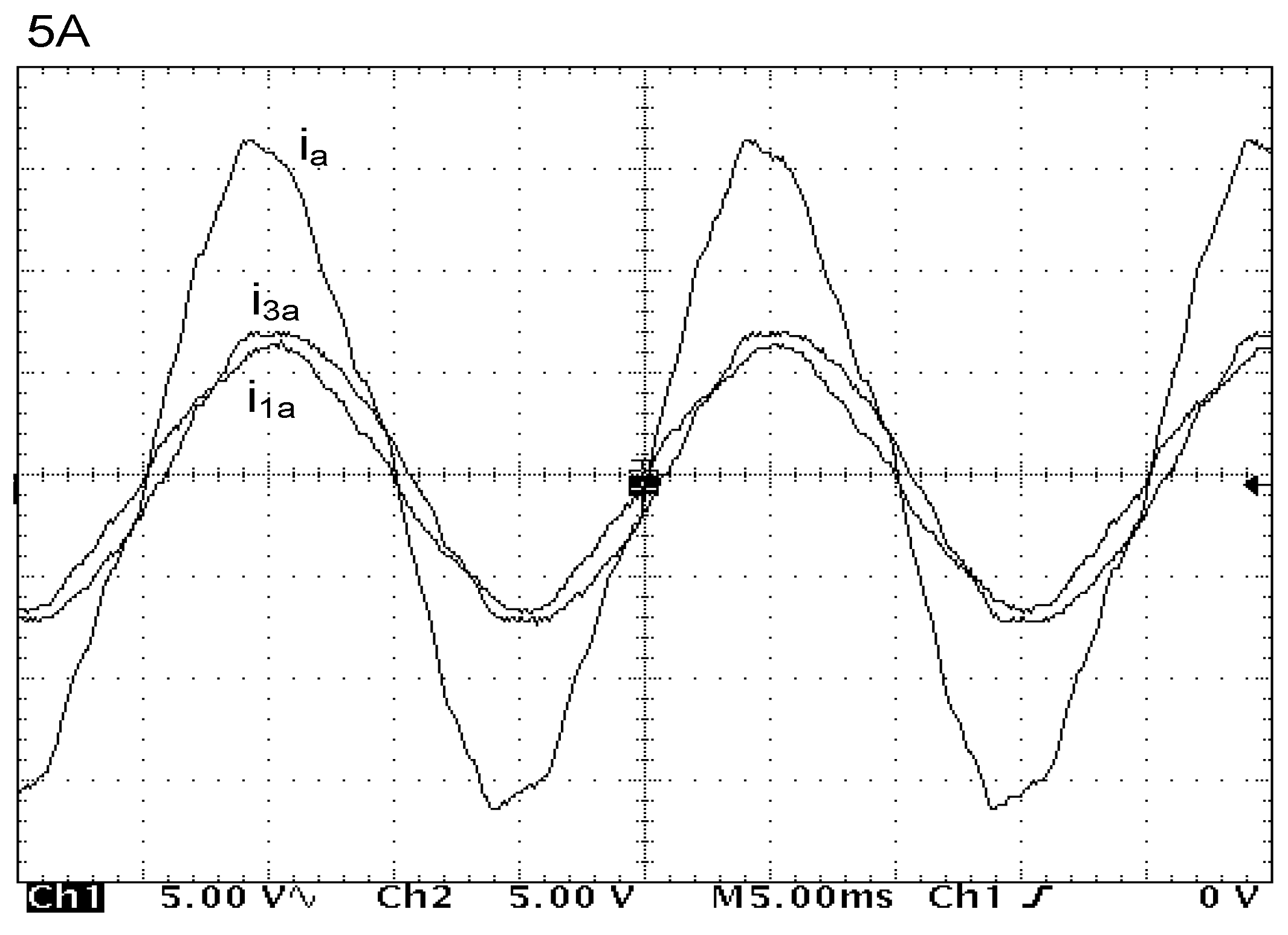
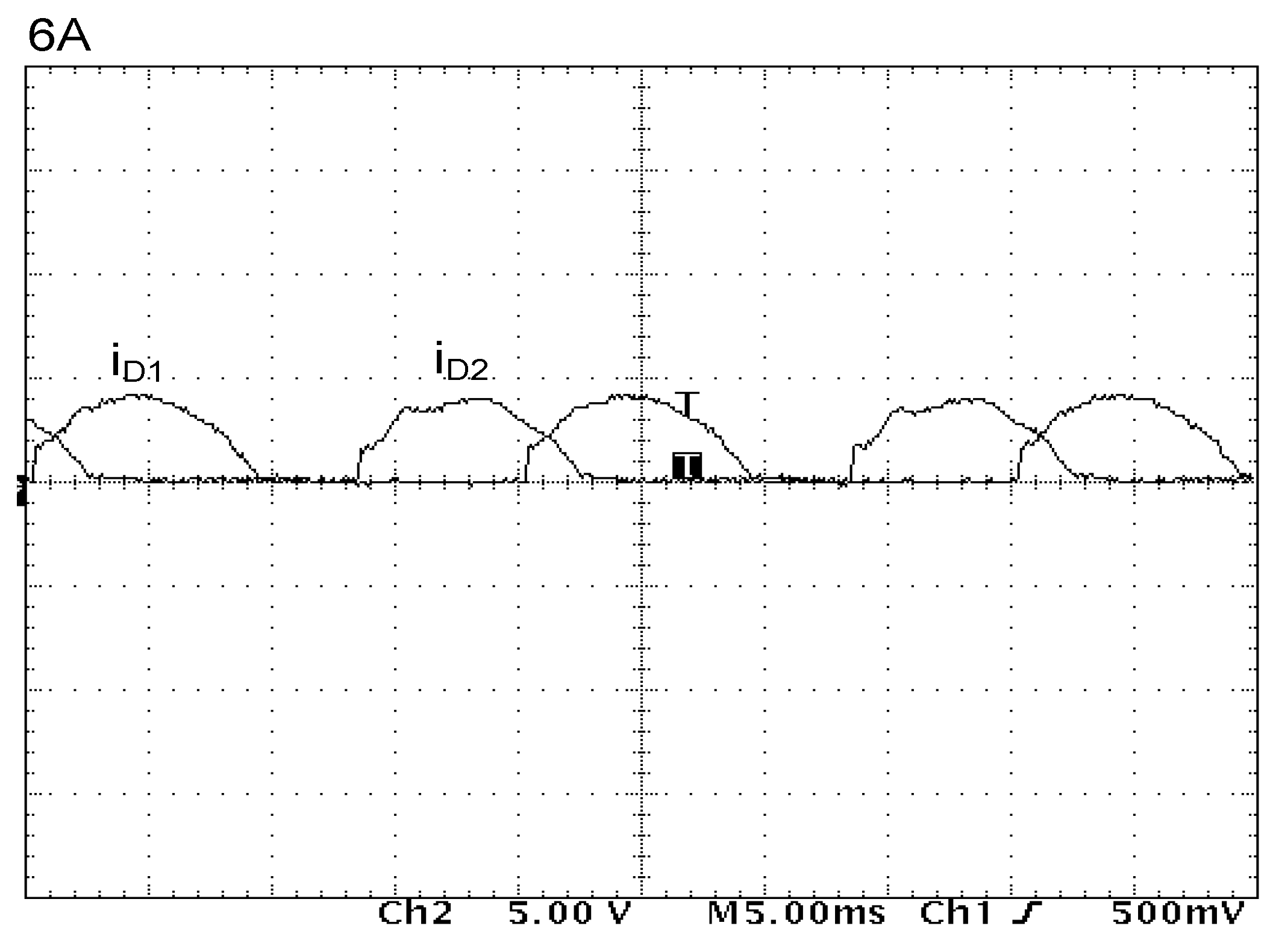
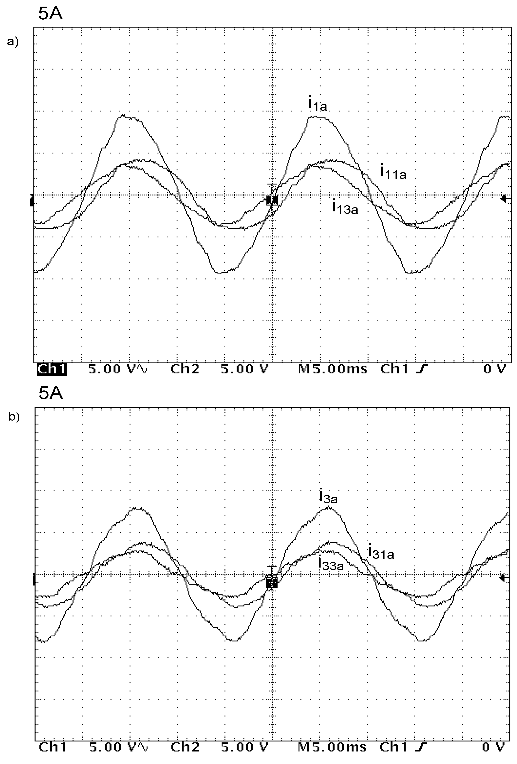
Experimental tests have been executed on the assumption that the three-level inverter introduces a load equal to 2 kW of power to the system. It was assumed that the state of the inverter was described by a voltage vector V
210 what meant that phase A had been connected to point 2 (
UD), phase B to point 1 (
UD/
2), and phase C to point 0. The successive
Figure 9,
Figure 10 and
Figure 11 illustrate the results of these tests. They include the following quantities: Phase, intermediary circuit and 3CRλ winding currents (
Figure 9), supply line voltage and current (
Figure 10) and their oscillograms presented in
Figure 11.
In general, the presented results of the simulation and experimental tests comply to a sufficient degree with the expected results. However, initial tests have been done at a very low level of load. Therefore, research work has been continued to realize a more powerful coupled reactor. The next chapter presents the completed results.
2.3. A Three-Level Inverter with 24-Pulse AC/DC Converter Using Three 3CRλ Units
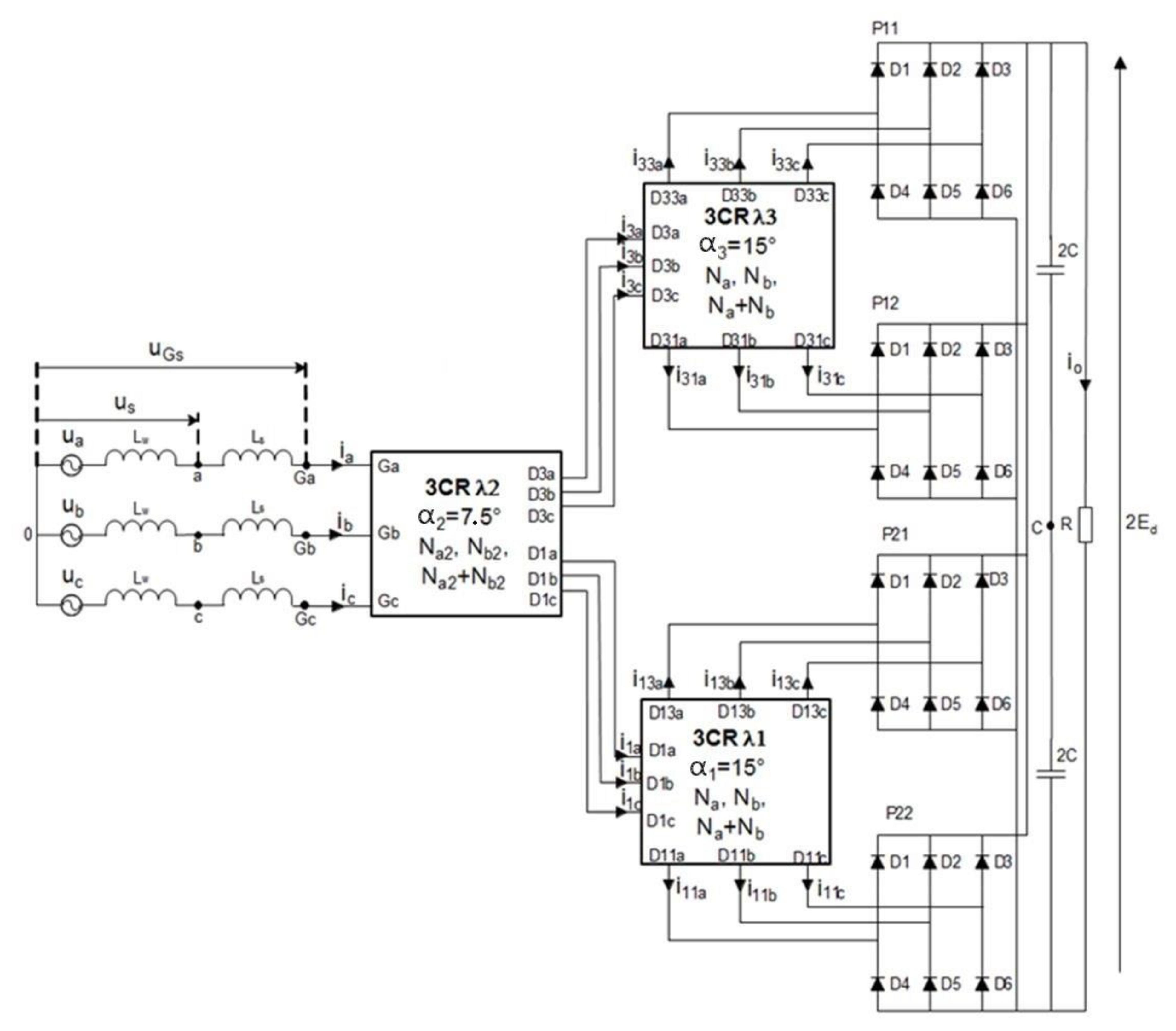
As mentioned above, in order to receive a higher number n-pulse converter supplying more than one standard rectifier it is possible to use more 3CRλ units. The 18-pulse rectifier has been analyzed before in several papers but the problem of multi-pulses rectifier is still analyzing and developing. In this chapter, the 24-pulse rectifier has been analyzed and some research results have been presented. The 3CRλ units are designed to permit mutual connection, thus giving more output voltages that are shifted adequately. Using three coupled reactor units in 3CRλ, it is possible to generate 12 output voltages supplying for instance four three-phase bridge rectifiers.
Figure 12 presents how the 3CRλ units are connected. As a result, it is possible to supply four three-phase bridge rectifiers. Connecting them in parallel permits them to receive a 24-pulse AC/DC converter generating a 24-pulse output voltage. This voltage is easy to filter by use of a limited bank of capacitors, even if the rectifier supplies a very high load.
The 24-pulse rectifier is destined to supply a three-level inverter. As presented in
Figure 3, the intermediary circuit is connected to three poles of the inverter, denoted as 2, 1, 0. As such, the output voltage of the rectifier is divided on two equal quantities. The problem of balancing this equally is not considered in this contribution. The load introduced by the inverter is represented here as a simple circuit [2C-2C] II [R] what means two capacitors 2C are connected in series and the resulting in capacitor is connected parallel to the resistance R. It was assumed to diminish some problems during simulation and experimental tests. The more advantageous connection of the 24-pulse rectifier to the intermediary circuit could be considered during further scientific research.
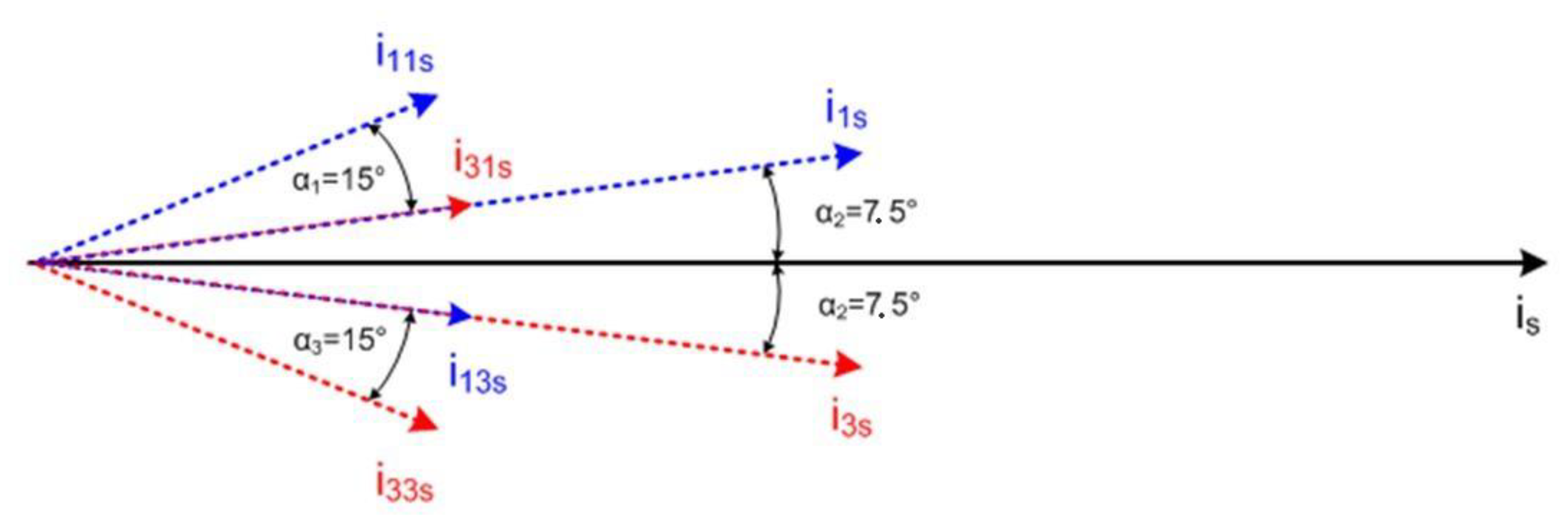
Next,
Figure 13 presents a diagram of current space vectors in order to explain the rule of creating four three-phase supply systems using 3CRλ units. The suitable voltages are induced on
Na2,
Nb2, and
Na2 +
Nb2 coils of the 3CRλ. They form a space voltage vector of the supply system. At the same time, they generate demanded currents that are mutually shifted. As a result, it is possible to obtain two voltage space vectors shifted by the angle of 2π/24. Every space vector determines a mathematical representation of the three-phase voltages. As such, the vectors here represent a supply network for 3CRλ1 and 3CRλ2 units.
It is necessary to care about the equal angle between output voltage space vectors of the 3CRλ1 and 3CRλ2. The angle should be 2π/12, which makes an obligatory condition of the 24-pulse AC/DC converter accurately work.
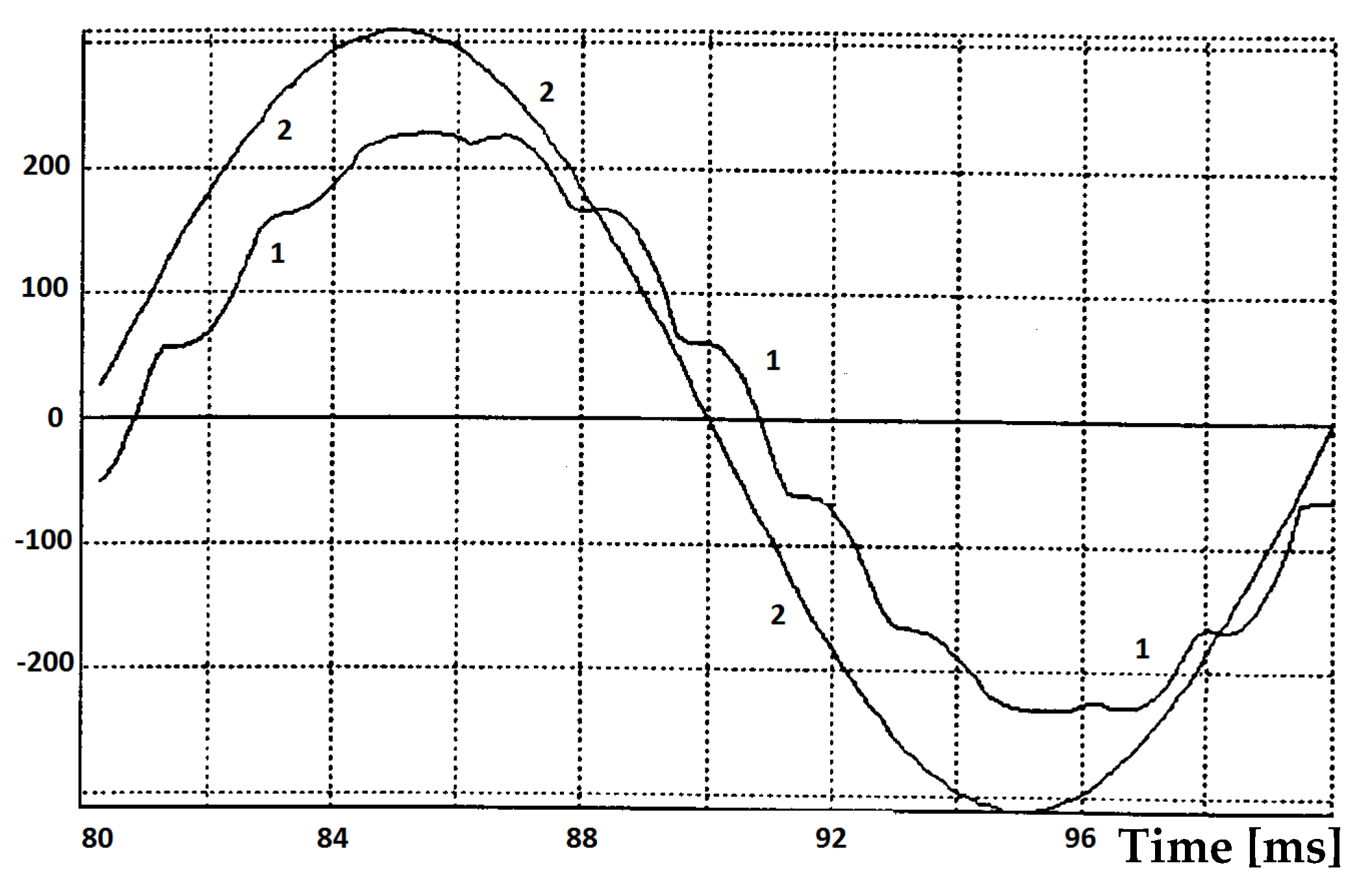
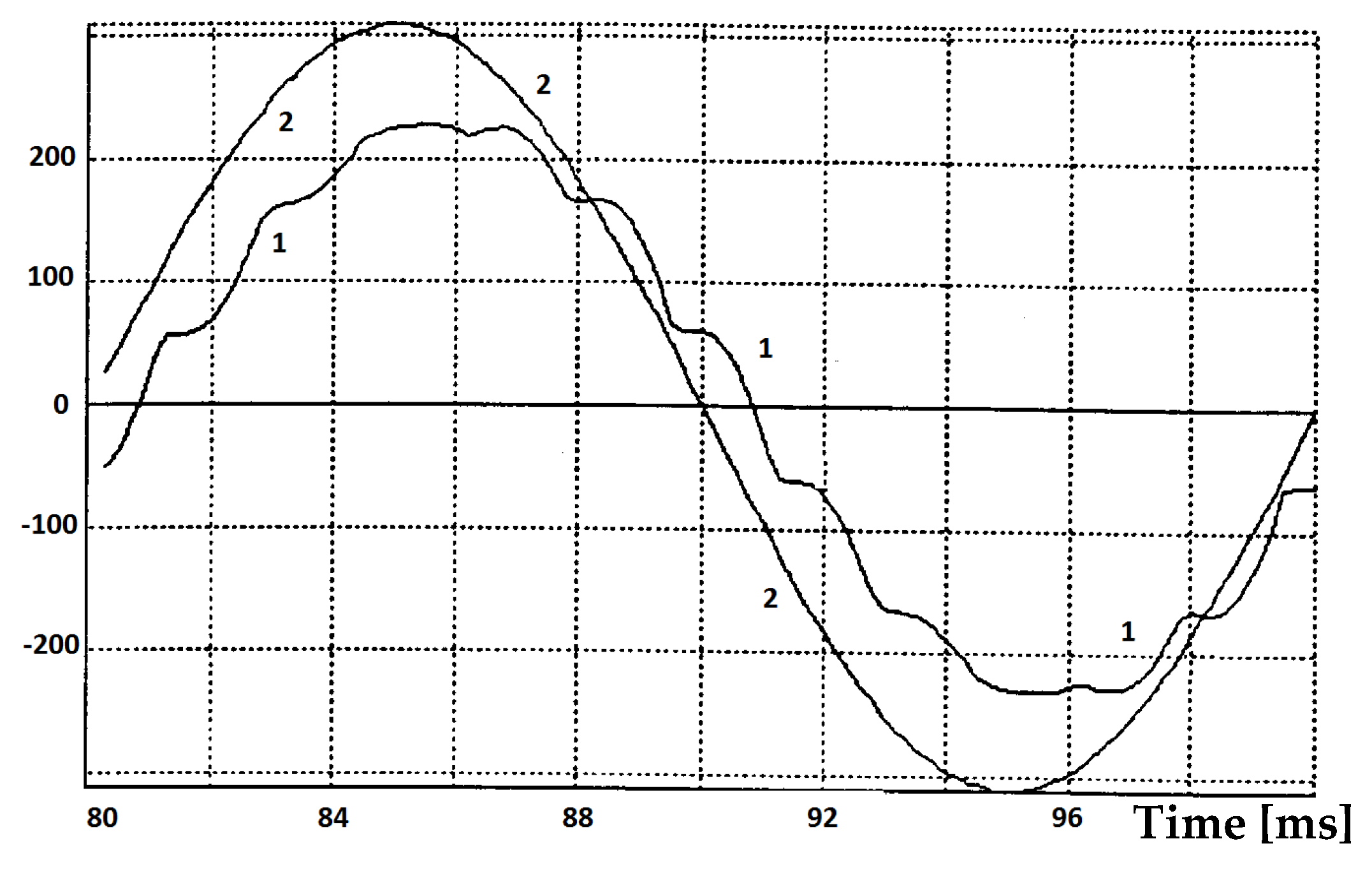
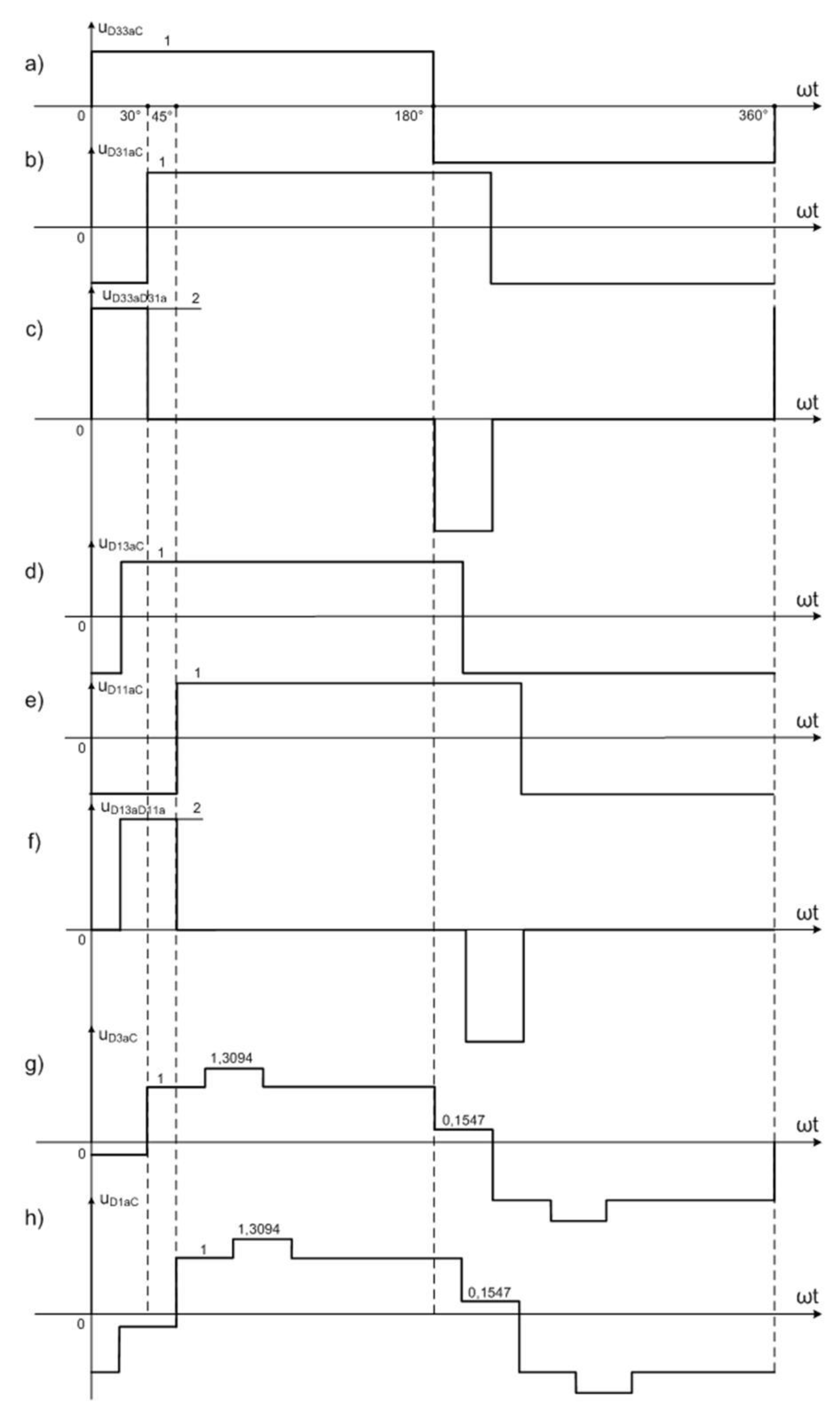
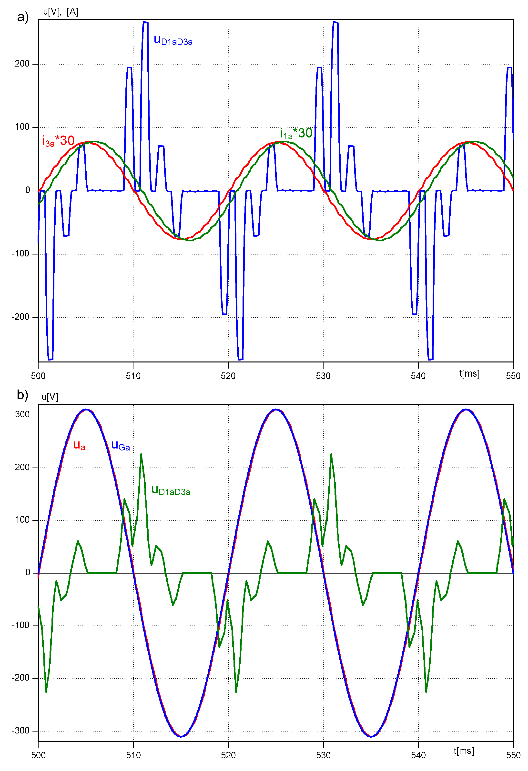
Different voltage and flux waveforms of the 24-pulse AC/DC converter based on 3CRλ units are presented in
Figure 14. All results have been gathered thanks to study methods and analysis. There are several waveforms presented, defining voltage between terminals
Dis or
Djs and point
C of the intermediary circuit. For instance, the voltage
is advancing voltage
by 30°, and voltage
is advancing
by 30°. Voltage waveforms on terminals
D13s–
D11s and
D33s–
D31s (
s =
a,
b,
c) are defined as a difference between voltage on terminals
D13s and
D11s, referenced to voltage on point
C:
. The same reasoning permits to define the voltage
. These waveforms are presented in
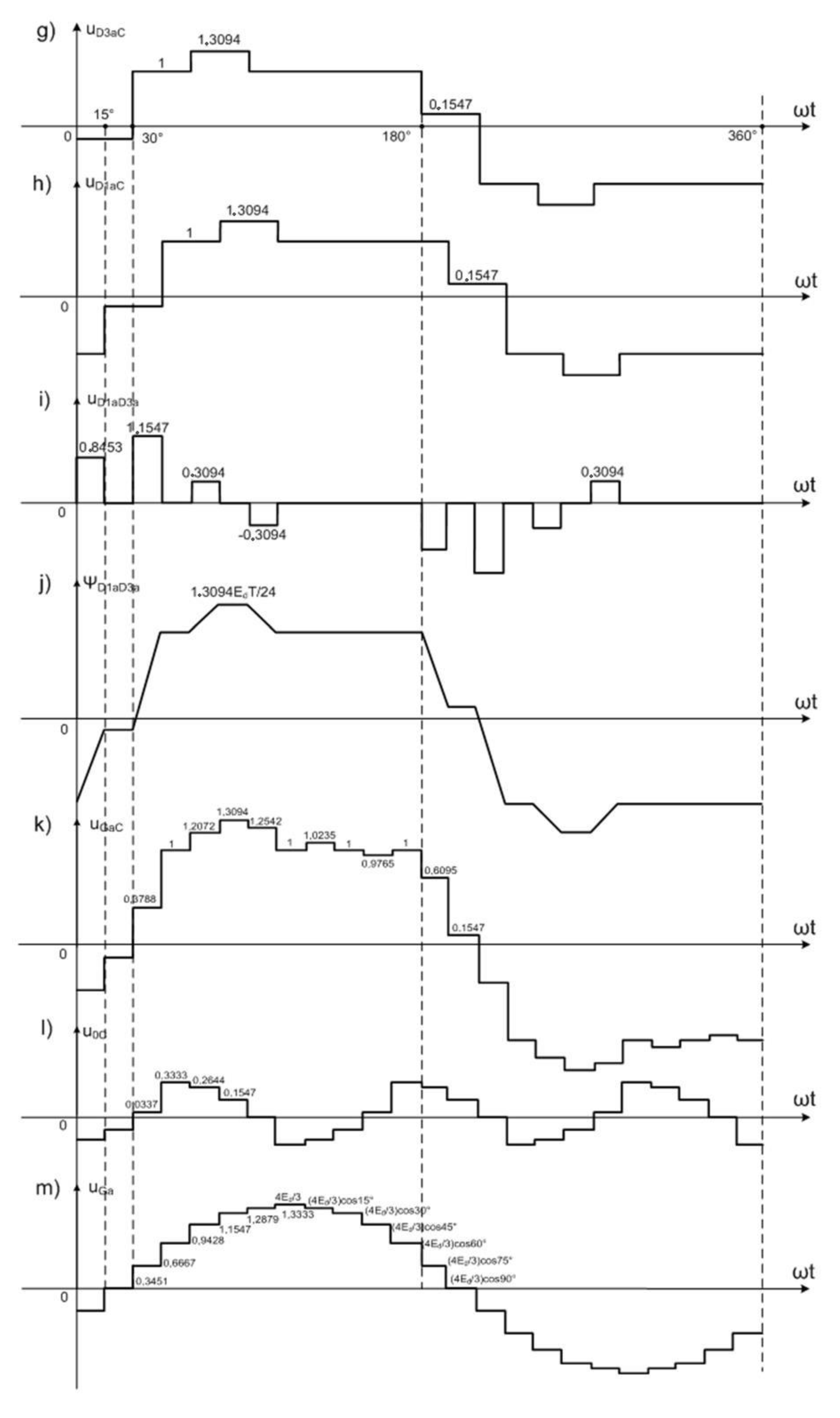
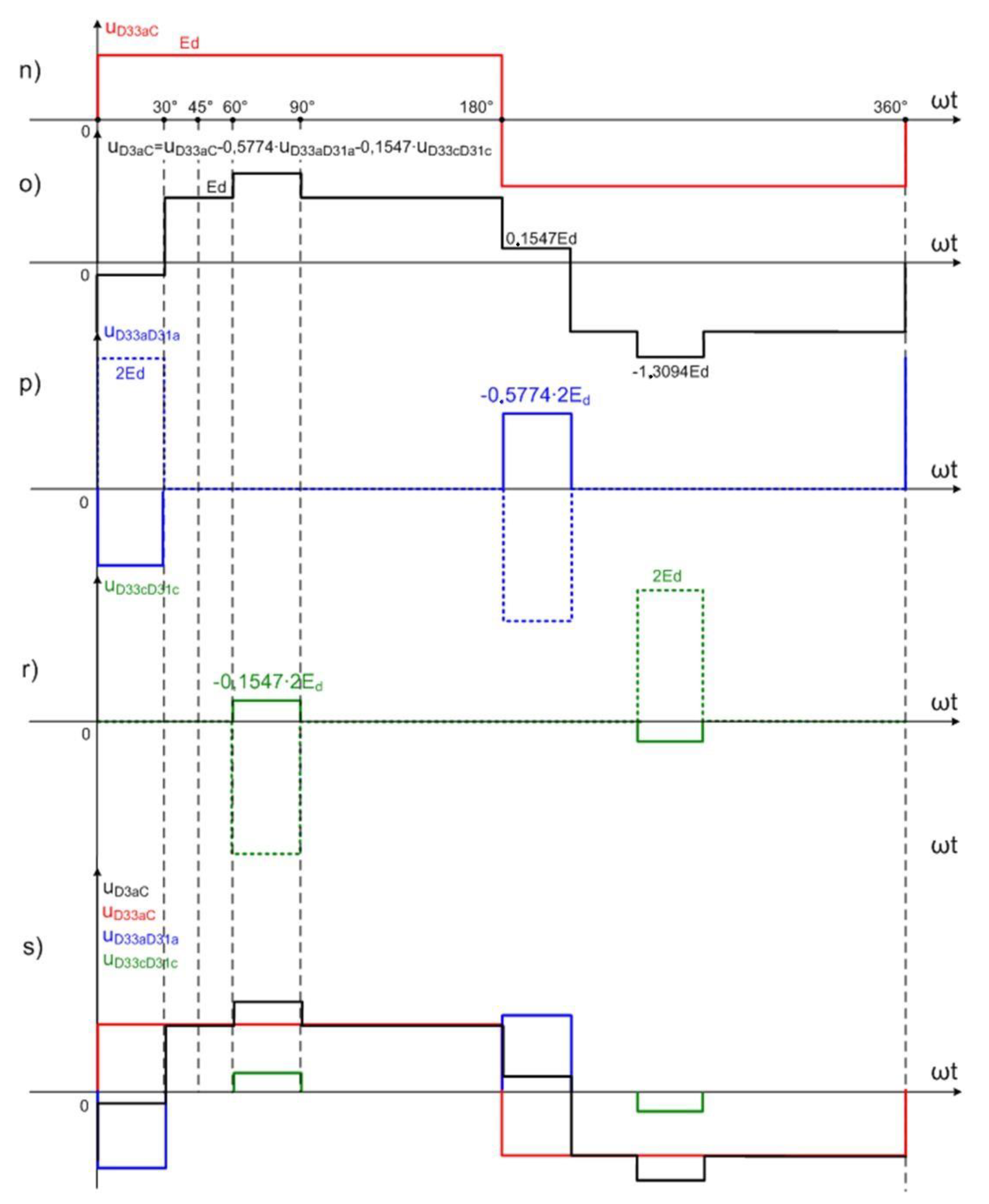
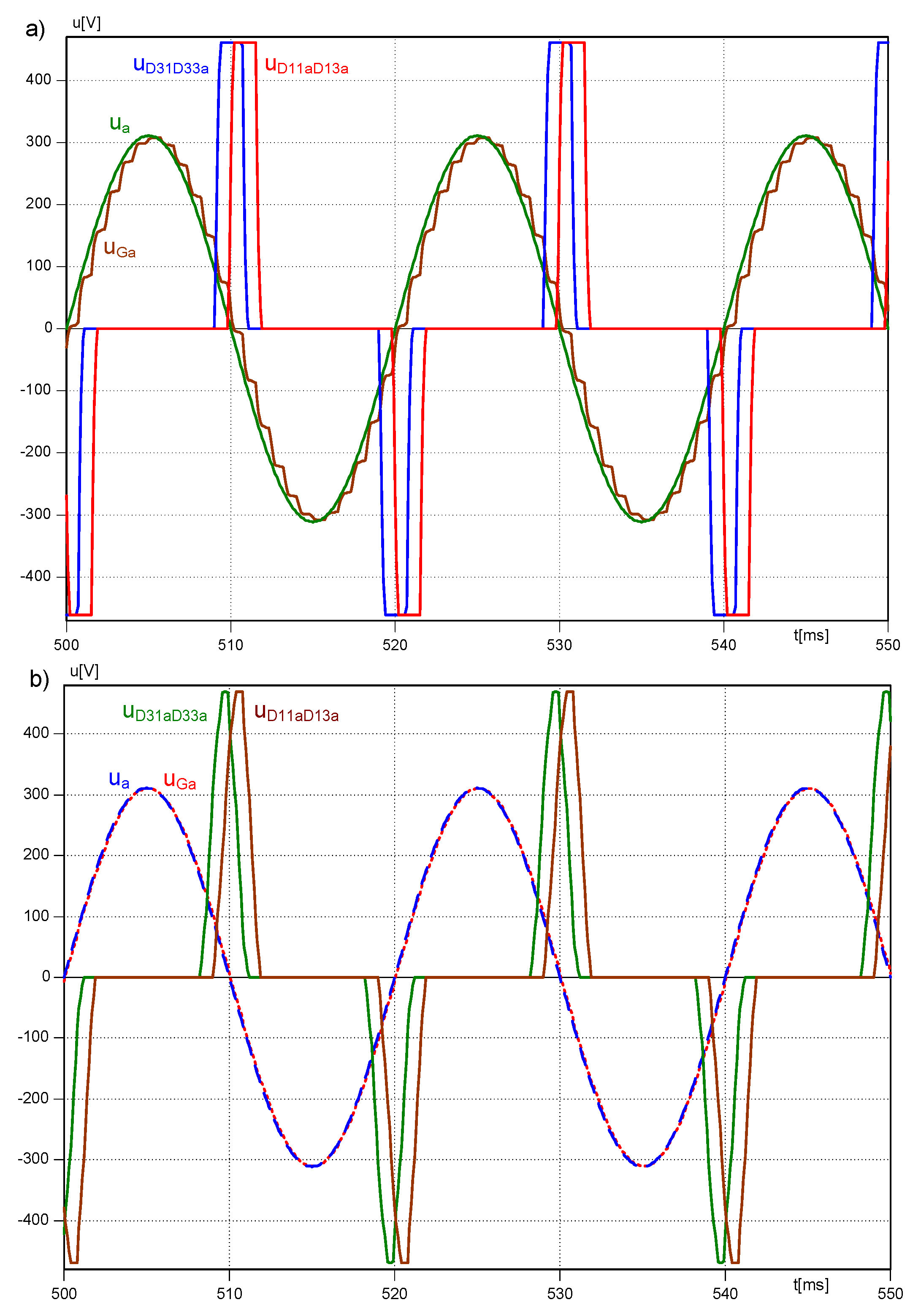
Figure 14c,f. It is unmistakable that the shift angle between them is equal to 15°. Successive waveforms and their construction method are presented in
Figure 15 and
Figure 16: diagrams i to s.
Voltages measured on terminals
D1s and
D3s of the 3CRλ2 unit are referenced to the point
C. The following equations present the determination principle:
where
Na and
Nb denote relevant coil numbers.
3. Simulation and Experimental Results of the 24-Pulse AC/DC Converter
Simulation and experimental tests have been executed on the assumption that the load introduced by the three-level inverter did not exceed 2 kW of power. The load was symbolized by the intermediary circuit presented in
Figure 12. It was assumed that the state of the inverter was described by a voltage vector V
210 or similar, e.g., V
021, which meant two sections of the intermediary circuit were loaded equally. Parameters of the simulation and laboratory model are collected in
Table 3.
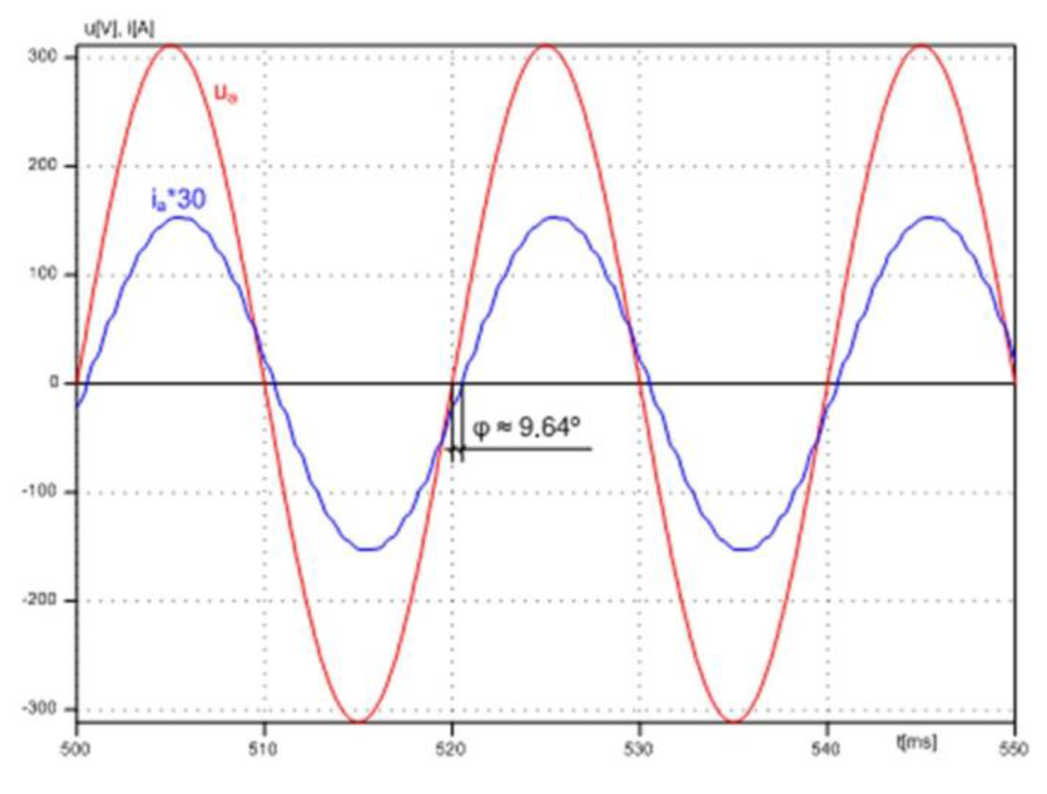
Waveforms of line voltage and current acquired during simulation tests are presented in
Figure 17. The shift angle between these quantities is small and does not exceed φ ≈ 9.64°.
The next figures present consecutive waveforms obtained during simulation tests.
Figure 18 illustrates output current waveforms of the 3CRλ2 unit as well as its voltages on main windings. The results in
Figure 18a have been acquired under full load conditions while in
Figure 18b at about 10% of the admissible load. Line voltage average value is equal to 0 and current waveforms are adequate.
Figure 19 and
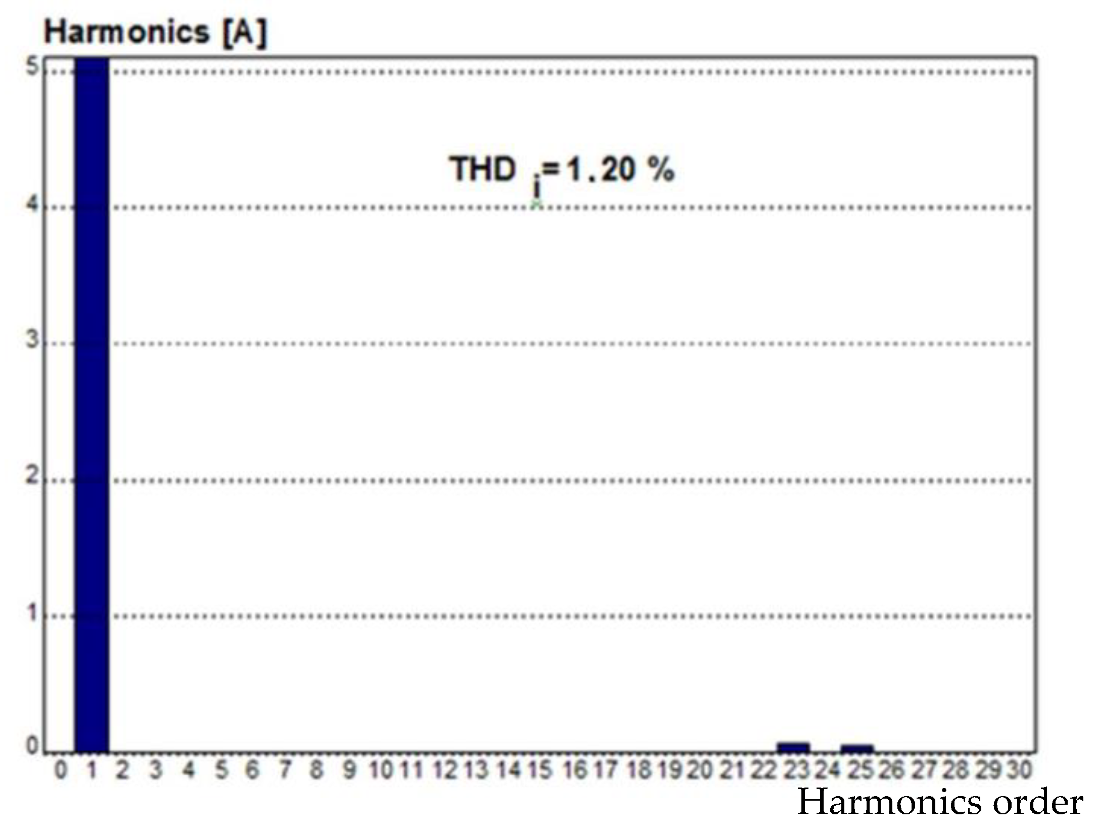
Figure 20 show consecutive results obtained during simulation tests. They prove the accurate performance of the system. All output currents have approximately sinusoidal shape, so their spectra and
THD factors fulfill standard requirements. The spectrum analysis and low
THDI presented in
Figure 21 confirms that condition.
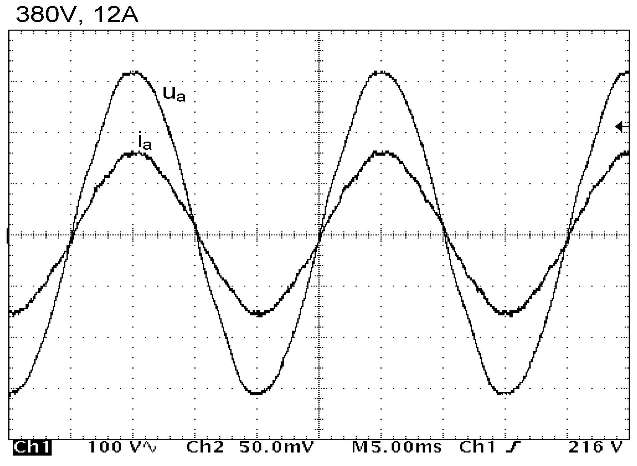
A laboratory model was designed after the simulation work. The model parameters were the same as assumed during simulation tests in order to carry out a comfortable comparison between the two models. The laboratory model has been equipped with a set of 3CRλ units. Experimental tests have been carried out in the power electronics laboratory of Gdynia Maritime University. The following
Figure 22,
Figure 23,
Figure 24 and
Figure 25 present the achieved results.
The spectrum analysis presented in
Figure 21 confirms a very good performance of the system supplying the 2 kW load. All diodes conduct current for half a cycle (180°). Higher harmonics are strongly suppressed. In the line current waveform harmonics of 23th and 25th are small and do not exceed 1.2% in relation to the fundamental harmonic. The
THDI factor is equal to 1.20%.
4. Conclusions
The results of the experimental tests comply to a sufficient degree with simulation testing and come close to the results obtained during theoretical considerations. The 12- and 24-pulse rectifiers act accurately and in accordance to expected results.
The applied solution based on magnetically coupled reactors improves the compatibility of such multi-pulse AC/DC converters. The essence of the operation based on coupled reactors consists of blocking (eliminating) higher current harmonics of the order of 6 k ± 1 in the output voltage. This result is obtained thanks to the satisfactory properties of the converter. First of all, line current waveforms are almost sinusoidal and are not shifted in relation to the line voltage. If the windings of the coupled reactors are precisely selected, the shift angle is close to zero, thus giving high power factor: cosφ ≈ 1. All diodes are conducting current during a half of cycle (180 degrees). As such, for assumed power, diodes rated currents are lower than in classical rectifiers. The diode current shape is strongly distorted in typical solutions, which implies the application of higher Imax semiconductor devices.
Multiplying standard 6-pulse rectifiers permits the diminishment of a capacitor bank of the intermediary circuit and defends a good stable DC voltage supplying the inverter. It is very important to assure its proper operation in conditions of fast changed load.
The applied magnetically coupled reactors and complexity of the multi-pulse rectifier can influence on the efficiency of the converter. Inductive elements insert an additional resistance to the circuit increasing power losses. Similarly, the additional inductance used, e.g. in inverters working as AC/DC rectifiers, have also a certain impact. An accurate design of reactors could limit the losses. Additional losses are derived from semiconductor devices. The 12-pulse rectifier has twice more diodes and the 24-pulse one four times more than a standard 6-pulse rectifier. That increases resistance losses proportionally to number of diodes. However, these multi-pulse solutions have advantages such as a very good power factor and good compatibility of the converter.
It seems that the 12-pulse rectifier as well as the 24-pulse one can be applied as useful supply sources of 3 level inverters. These converters permit to block higher current harmonics what leads to considerable reduction of the current distortion factor and to improve the compatibility of the whole system consisting from a multi-pulse rectifier and a three-level inverter.


