Article

Study on Riblet Drag Reduction Considering the Effect of Sweep Angle

1
School of Aerospace Engineering, Tsinghua University, Beijing 100084, China
2
Key Laboratory of Aerodynamic Noise Control, Mianyang, Sichuan 621000, China
*
Author to whom correspondence should be addressed.
Energies 2019, 12(17), 3386; https://doi.org/10.3390/en12173386
Submission received: 18 July 2019 / Revised: 26 August 2019 / Accepted: 28 August 2019 / Published: 2 September 2019

Abstract

:
This study computationally evaluates the riblet drag reduction effect considering the effect of sweep angle. An implicit large eddy simulation is performed on a channel flow and an infinite swept wing. First, three different inclined angles between the riblets and the flow direction are tested in the channel flow. The results show that with increases in the inclined angle, the friction drag decreases, while the pressure drag increases approximately quadratically. The riblets with a 30° inclined angle increase the total drag of the channel flow. Then, an infinite wing with a 30° swept angle with and without riblets is studied. The riblets demonstrate satisfactory drag reduction efficiency because the cross flow over most parts of the wing is mild. The lift and friction drag follow the relation of the cosine law of a swept wing. Moreover, the cross flow and the turbulence fluctuation are suppressed by the riblets.

1. Introduction

The economic efficiency and energy consumption of a civil airplane in flight is directly related to the aerodynamic drag. A one-unit increase in the drag coefficient (ΔCD = 0.0001) of the supersonic Concorde airplane was equal to a capacity of two passengers, i.e., approximately 2% of the total capacity [1]. For the C-5 military transport plane, a one-unit increase in drag represents a loss of 450 kg of payload capacity [2]. Drag reduction is therefore one of the most important goals of aircraft design. The Flightpath 2050 perspective formulated by the Advisory Council for Aviation Research and Innovation in Europe aims to reduce the energy requirements of airframes and propulsion systems by 68% before 2050 (referenced to the year 2000) [3]. The aerodynamic drag must be greatly reduced to achieve this goal of 2050.
The aerodynamic drag can be decomposed to wave drag, profile drag and lift-induced drag [4]. The profile drag is a parasitic drag and includes the friction drag and the form drag, which are useless for lifting the aircraft. The use of riblets is a passive method for reducing profile drag. This method can restrict turbulent coherent structures inside the boundary layer and lessen the generation of vortex structures, consequently reducing the energy loss and the friction drag [5]. A flight test of the T-33 airplane showed that the installation of riblets produces a reduction of approximately 6% in the local friction [6]. The friction reduction percentage can reach as high as 10% using riblets with optimized shapes and sizes [7]. According to the estimation of Bechert et al., [8], approximately 8–10 units of total drag reduction is achievable for an Airbus A340 aircraft by coating 70% of the surface in riblets; furthermore, the weight of the riblet film is only in the order of 100–250 kg, which is far less than the benefit produced by the drag reduction.
The riblet film is a practical passive flow control measure. Many researchers have focused on the drag reduction mechanism. Walsh [9] analyzed the process of the bursting process of the boundary layer streak and concluded that riblets constrain the oscillation and growth of the low-speed streaks; hence, the streak eruption is damped. Additionally, riblets can elevate the viscous sublayer of the boundary layer. A virtual origin is helpful for describing the velocity profile of the boundary layer with riblets [10]. The displacement from the virtual origin to the riblet tip is called the protrusion height. The drag reduction effect was reported to be associated with the protrusion height [11]. Luchini et al., [12] found that the virtual origins caused by riblets for streamwise flow and cross flow are different. The virtual origin of the cross flow is higher than that of the streamwise flow; consequently, the cross flow is restrained to a greater degree than the streamwise flow, and the boundary layer development process is suppressed [12]. Moreover, riblets that have a larger protrusion height difference have a better drag reduction effect [13]. Goldstein et al., [14] also reported that the damping effect of the spanwise flow fluctuations was the reason for drag reduction. Krieger et al., [15] demonstrated that the refined streamwise groove is able to prevent breakdown of the flow transition process and promote laminar flow. Strand et al., [16] reported that riblets can restrain the spreading angle of the turbulence spot.
The drag reduction mechanism of streamwise riblets has been widely studied. The shape and size of the riblets have also been investigated by many researchers [8,13,17]. A riblet tip-to-tip distance of s+ ≈ 15–20 (based on the wall unit) and height/width ratio of h+/s+ ≈ 0.5–1.0 are supposed to produce a good drag reduction effect [18]. The adverse pressure gradient under real flow conditions is good for the drag reduction efficiency of the riblets [19]. However, the drag reduction effect strongly depends on the flow direction. An experiment of Sundaram et al., [20] showed that the drag reduction ratio of a swept wing decreases from 8% to 1% for the spanwise flow when the angle of attack increased from 0° to 6°. Benschop and Breugem [21] reported that the drag reduction ratio of riblets drops from 9.3% to 0.9% when the channel yaw increased to 15° with respect to the flow direction. When the flow angle is different from the riblet direction, additional pressure drag is induced. Peet et al., [22] reported that the pressure drag scales with the square of the riblet shape angle: CD,p ~ (tanβ)2. Ghebalia et al., [23] studied the drag reduction effect of skewed wavy walls. They found that the friction drag reduction behaves approximately quadratically or linearly for different wavy walls, while the pressure drag always increases quadratically. If the riblet height increases, the pressure drag penalty becomes more intense [24]. The total drag change depends on the synthesis of the friction drag benefit and pressure drag penalty. However, the drag reduction effects and the flow phenomena of the riblets in sweep angle are not clear. For instance, two research groups have contrary conclusions regarding the drag reduction efficiency of herringbone riblets. Chen et al., [25] concluded that herringbone riblets have an excellent drag reduction effect, while Benschop and Breugem [21] found that herringbone riblets increase drag considerably.
In this paper, the drag reduction effects of a channel and an infinite swept wing were computationally studied. The computational method is validated in our previous paper [5]. In this paper, a channel flow with one side covered by riblets was firstly computationally investigated. The channel was yawed at angles of 0°, 15° and 30° to study the flow structures of the riblets under different inclined angles. Then, an infinite 30° swept wing constructed based on the airfoil Eppler E374 [26] was computed. To the authors’ knowledge, this is the first to present large eddy simulation (LES) results of the riblets under sweep angle. The result of an unswept infinite wing with riblet film was also compared. A numerical trip was used to ensure the flow transition from laminar to turbulent. The drag reduction effect and Reynolds stress variation caused by riblets were analyzed.

2. Riblet Effect in a Channel with an Inclined Angle

2.1. Computational Methods

In this paper, an implicit large eddy simulation (ILES) was conducted based on a finite volume structured code [5,27]. The three-step explicit Runge–Kutta method was used for time advancing. There was no explicit subgrid-scale model used in the simulation. The dissipation effect of turbulence was approached by the numerical dissipation of the spatial discretization scheme. The code adopted a low-dissipation scheme that combined the minimum dispersion and controllable dissipation [27] scheme for the reconstruction of the conservative variables and the simple low-dissipation advection upstream splitting method (AUSM) scheme [27] for the Riemann solver. Both the schemes of the reconstruction and Riemann solver were constructed with low dissipation features. The computational method was validated with high resolution and good all-speed performance [27], although it was a 2nd-order scheme. The code has been tested on some basic flows [27] and has been applied to channel flow and airfoil flow with riblets [5] in our previous studies. This paper is a follow-up study to our previous investigation; consequently, a validation of the code is not presented here.

2.2. Computation Settings for a Channel with Riblets

In this section, blade-type riblets [13] were installed on one side of a channel. Following our previous study [5], the Reynolds number based on the half-channel height δ and the mean flow velocity UAVG was 2800. Here, UAVG = m ˙ / A , where m ˙ is the total mass flow and A is the channel section area. To study the riblet effect under inclined angle, the incoming flow of the channel had a yaw angle with the riblets. The streamwise length (x direction) and spanwise length (z direction) of the computational domain were 2πδ and 1.54δ, respectively, as shown in Figure 1a. The wall-normal direction (y direction) range of the computational domain was from −0.025δ to 2δ. The riblets were installed on the lower boundary of the y direction. The lower boundary was shifted downward according to the virtual origin [10] of the riblets. The upper wall boundary was flat. Figure 1b,c shows a sketch map of the riblets and the geometry of the riblets. Sixteen riblets were located on the lower boundary. Bechert et al., [13] reported that blade-type riblets have better drag reduction efficiency than sawtooth or scalloped riblets. Blade riblets with a spanwise width of s+ = 17 (based on wall unit) and a height/width ratio of h+/s+ = 0.5 have the largest drag reduction ratio [13]. The geometry and size of the present riblets were based on the optimal results of Bechert et al., [13]. As shown in Figure 1c, the spanwise length s of each riblet was 0.0965δ, and the riblet height h was 0.0482δ. The thickness of the riblets was 0.002δ.
The computational grid near the riblets is also shown in Figure 1c. The total cell number was 10.8 million, which included 160, 170 and 384 cells distributed in the streamwise, wall-normal and spanwise directions, respectively. The present grid density was between the coarse and fine grids in our previous study [5]. The first layer height in the wall-normal direction was 0.001δ on both the flat and riblet sides. The first layer Δy+ was collected after LES computation. The averaged Δy+ of the first grid layer was approximately 0.17 on the flat side, which means that the grid was sufficient for resolving the large eddies in the boundary layer of the flat plate. In the spanwise direction, there are 25 points evenly located between two riblets. The spanwise cell size was approximately four times the height of the first layer. Figure 2 shows the averaged first layer Δy+ of the bottom wall boundary and Δz+ of the riblets when the riblets were parallel to the main flow direction. The Δz+ was computed based on the grid scale normal to the blade-type riblet and the local friction velocity on the riblets. The Δy+ of the bottom wall was less than 0.1. The maximum Δz+ on the riblets was less than 1.2 and was located at the riblet tip.

2.3. Riblet Drag Reduction Effect under an Inclined Angle

To study the drag reduction effect of riblets under an inclined angle, the main flow of the channel had an inclined angle α with the riblet direction, as shown in Figure 1b. Three angles, α = 0°, 15° and 30°, were computationally studied in this paper. When α = 0°, the riblet direction was parallel to the main flow direction. When α = 15° and 30°, the riblets were located along the x direction rather than the main flow direction.
The computations were carried out on an Intel 2.2 GHz 256-core cluster. The dimensionless timestep ΔtUAVG = 0.00034 was applied for the cases. A fully developed channel flow was interpolated to the computational grid as the initial condition. Approximately two million steps were computed for each case, and the total number of nondimensional time units (tUAVG) computed was approximately 680. The total computational cost was approximately 60000 CPU core hours for one case. The mean flow quantities were collected after 200 time units when the flow reached a statistically-steady state. Figure 3 shows the histories of the drag coefficients on the two sides of the channel when α = 0°. The red solid curve is the drag coefficient of the flat side. The black dashed curve is the drag coefficient of the riblet side. It is obvious that the riblet side had a lower drag coefficient than the flat side.
Table 1 presents the statistical drag coefficients of three cases with different inclined angles. The characteristic velocity was the mean flow velocity of the channel. The CD in the table means the total drag, which includes the friction drag CD,f and the pressure drag CD,p. However, there was no pressure drag on the flat side; consequently, the friction drag and the total drag were the same. All surfaces of the riblets were integrated for the drag coefficient, and the drag coefficients were obtained through vector synthesis of the streamwise components of the forces in x and z directions. The low-speed turbulent flow was influenced by both sides of the channel, therefore the friction drag coefficients of the flat side of the three cases were not identical to those of the riblet side but were very close. The friction drag on the riblet side decreased with the inclined angle. In contrast, the pressure drag on the riblet side increased approximately quadratically with the inclined angle, as the pressure drag of the 30° case was approximately four times that of the 15° case. The total drag was reduced by 7.8% and 6.4% at α = 0° and 15°, respectively, but was increased by 3.3% at α = 30°.
Figure 4 shows the mean streamwise velocity distributions at four points. The profiles were normalized based on the wall friction of the flat side. The four points are illustrated in Figure 1c. The points A, B and C were evenly distributed between two riblets. Point D was on the riblet tip. Notably, the u velocity in this figure was the resultant velocity parallel to the mean flow direction. The velocity was averaged along the riblet direction and phase averaged along the spanwise direction because each riblet was isotropic. The velocity profiles of three different riblet angles and the flat side are all presented in the figure. The laws of the wall (u+ = y+ and u+ = 2.5 lny+ + 5.5) were also plotted for comparison. The velocity profile of the flat side of the channel matches well with the laws of the wall. The log-law regions at 30° were all lower than those at 0° and 15°, as well as the flat side. Compared with the flat side, the Δu+ values at 0°, 15° and 30° were approximately 0.47, 0.31 and −0.44, respectively. A positive shift in the log-law means drag reduction, while a negative shift means drag increment [28]. The viscous sublayer of the three riblet surfaces was different from that of the flat side because the wall of the riblet surface was not located at the y = 0 location. At point A, which was close to the windward side of the riblet, the sublayer profiles of the different riblet angles were quite close. At points B and C, the sublayer of the 0° case had the largest velocity gradient, leading to the largest friction drag.
Figure 5 displays the root mean squares of the velocities and Reynolds shear stress u v ¯ . The root mean squares of the velocities are equivalent to the square root of the Reynolds normal stresses. Again, the velocity u was parallel to the channel mean velocity (which differed in direction from the riblet direction), and the w was normal to the mean velocity. The right sides (y/δ = 2.0) of the figures show the results for the flat side, and the left sides show the results for the riblet side. The Reynolds stresses near the flat side were the same for all three cases. However, on the riblet side, the vrms, wrms and u v ¯ of the α = 30° case were significantly higher than those of the other two riblet angle cases. In particular, the u v ¯ was directly linked to the generation of friction drag, which verified the increasing drag phenomenon of the α = 30° case. The Reynolds stress distributions of α = 0° and 15° were quite similar, and their drag reduction ratios were also very close.
Figure 6 shows the instantaneous flow fields of the cases. All fields were plotted at an arbitrary moment after reaching the statistically-steady state. The turbulent vortex structures were identified by the Q-criterion with Q(δ/U)2 = 1. The vortices are colored by the streamwise velocity u/UAVG. The figures were copied one time in the spanwise direction to demonstrate the vortex structures. With increasing riblet angle, the regular straight small vortex structures under the riblets became abundant. The irregular streak and hairpin vortices at α = 0° and 15° were clearly less than those of the flat side. For the α = 30° case, the color of the vortex structures is lighter than that of the others, which means that the velocity was lower and that the height of the turbulence structure was lower. The result showed that with large inclined angle α = 30°, the turbulence structures could become fully developed at a lower flow speed.
The results of riblets showed that the riblets could reduce drag when the incline angle of the riblet and the flow direction was small. In the present computation, an inclined angle of 15° shows good drag reduction efficiency, while an inclined angle of 30° produced an increase in drag. Thus, the friction drag decreased with the incline angle. Although the pressure coefficient variation caused by the riblets was limited, the pressure drag increased rapidly with the incline angle. The velocity profile and Reynolds stress distributions validated the drag variation of the different cases.

3. Effect of Riblets on an Infinite Swept Wing

3.1. Computational Settings

In this section, the riblet film was installed on a swept wing. The wing was based on the Eppler E374 airfoil [26]. It had a 30° sweep angle. The spanwise boundaries were set as periodic boundary conditions; thus, the wing was equivalent to an infinite wing. The thickness of the airfoil and the angle of attack were scaled by a factor of cos(30°) based on the cosine law of the swept wing [29] to make the result comparable to the unswept Eppler E374 airfoil. The incoming flow Mach numbers and Reynolds numbers were also scaled by 1/cos(30°). Consequently, the incoming flow Mach number M of the 30° swept wing was 0.231, the Reynolds number Re was 2.31 × 10⁵, and the angle of attack was 2.59°. Thus, the values for the wing were equivalent to an unswept wing with M = 0.2, Re = 2.0 × 10⁵ and α = 3° according to the cosine law.
Figure 7a shows the riblet film configuration of the present computation. The riblet film was located at 0.3 ≤ x/c ≤ 0.99 (c is the chord length of the airfoil). The film has a length of 0.02 c for changeover from the smooth surface to the riblet surface. The Reynolds number was low, therefore a numerical trip formed by steady blowing and suction was applied at x/c = 0.13 to ensure the transition from laminar to turbulent flow. The blowing and suction locations are illustrated as blue and red spots in Figure 7a. The effectiveness of this numerical trip is demonstrated in our previous study [5]. Figure 7b illustrates that the riblet direction was along the airfoil and was the same as the free stream direction.
The computational domain was from −20 c to 20 c in the x direction and from −16 c to 16 c in the y direction. The spanwise domain size was 0.05 c. Figure 7c shows the computational grid in the xy plane. The grid was a C-type grid. It has 1321 points in the circumferential direction and 181 points in the wall-normal direction. The mesh in the figure is plotted at every two points in both directions. The grid spacing of the first wall-normal layer was 1.0 × 10⁻⁴ c. There were 241 points placed in the spanwise direction. The total grid number was 57.6 million. The grid point number and distribution were the same as our previous study [5], which exhibited sufficient grid resolution for LES. Twenty riblets are computed in the present study, and each riblet has 12 points in the spanwise direction. The cross section of each riblet was an isosceles triangle, as shown in Figure 7d. The height h of each riblet was 0.002 c, and the valley-to-valley distance s was 0.0025 c. The riblet size demonstrated good drag reduction effect in our previous study [5].
The spanwise correlation of the wall pressure was computed to test the adequacy of the spanwise domain size. Figure 8 shows the autocorrelation at several streamwise locations. The correlation was computed based on the homogenous locations along the spanwise direction. Although the wing had a 30° sweep, the correlation decayed rapidly in the spanwise direction. The largest value of correlation at z/c = 0.025 was less than 0.13, which was at the location of x/c = 0.9. It demonstrated that the spanwise computation domain was sufficient in the present computation.

3.2. Aerodynamic Coefficients of the Swept Wing with Riblets

The smooth swept wing and the wing with riblets were computationally investigated and compared. Because the grid of the wing with riblets was deformed from the baseline smooth wing grid, the wall-normal spacing of the first grid layer near the riblet tip was decreased. Consequently, the time steps of the two cases were different. The time step ΔtU/c was 1.16 × 10⁻⁵ for the smooth wing and 8.09 × 10⁻⁶ for the wing with riblets. The total simulation time tU/c of the two cases was approximately 24.5, and the computations after tU/c = 16 were used for statistical collection. The total computation cost of the smooth wing was approximately 3 × 10⁵ core hours and that of the wing with riblets is approximately 4.3 × 10⁵ core hours on an Intel 2.2 GHz cluster.
The results of channel flow in Section 2 demonstrate that the riblets were workable when the inclined angle of the riblets and the mean flow direction was 15°; by contrast, the riblets lost their efficiency when the inclined angle was 30°. The surface limiting streamline of the smooth airfoil was averaged through the simulation, as shown in Figure 9. The contour in the figure shows the local flow angle β, which was computed by the streamwise velocity and the spanwise velocity. It was clear that the flow angle of x/c < 0.8 (except the leading edge) was less than 15° and that the cross flow was weak. This finding meant that the riblets in this region were effective. In contrast, the cross flow near the trailing edge was strong, and the flow angle was larger than 30 degrees, which meant that the effectiveness of riblets in this region was questionable. In particular, because of the strong cross flow and laminar flow nature, the flow near the trailing edge of the lower surface was separated. If the riblet film is installed on this region, it may increase the drag coefficient. In combination with a database of drag reduction ratios varying with the riblet angle, the surface limiting streamline is helpful for determining the riblet direction for aircraft applications, which is easy to obtain by Reynolds-averaged Navier–Stokes simulation.
Figure 10 shows the histories of the force coefficients of the smooth wing and the wing with riblets. The force coefficients displayed oscillation with a small amplitude, which demonstrated that the computation was statistically converged. After the riblet film was installed on the wing, the lift coefficient was increased, and the total drag and friction drag were both decreased.
Table 2 provides the averaged lift and drag coefficients of the computations. Similar to the airfoil simulation [5], the lift coefficient was increased by 5.4% by the riblets in the present study, and the total drag was decreased by approximately 8.5%. The drag reduction was mainly induced by the friction drag, while the pressure drag was increased. According to the empirical relation [29], the aerodynamic forces of an airfoil and a swept wing can be expressed as Equations (1)–(3). Λ is the sweep angle. The lift and drag coefficients estimated from Equations (1)–(3) are also shown in Table 2. It was clear that the lift coefficient and the friction drag coefficient followed the empirical relations well, while the pressure drag of the swept wing was larger than the estimated value. However, the pressure drag and friction drag variance ratios of the present computation and estimation were quite close.
CL,sweep = CL,airfoil cos2Λ
CDp,sweep = CDp,airfoil cos3Λ
CDf,sweep = CDf,airfoil cos0.2Λ
Figure 11 presents the averaged pressure coefficients. The 0° sweep results were scaled by a factor of cos2Λ. The pressure distribution patterns of the 0° and 30° sweep angles were similar and matched well. A pressure jump appeared at the beginning location of the riblets, which may have caused the pressure drag to increase.
Figure 12 shows the skin friction coefficients of the wing without and with riblets. The skin friction coefficient increased abruptly at the trip location. Then, it slowly decreased in the streamwise direction for the smooth wing. For the riblet-covered wing, the skin friction coefficients at three points A, B and C, which represented the riblet tip, middle and valley as shown in Figure 7d, are all presented. The point B was the midpoint between the riblet tip (point A) and the valley (point C). The skin friction had a sharp peak at the riblet tip at the beginning of the riblet film and then decreased rapidly. The lowest friction value of the riblet tip appeared at x/c = 0.5, where the adverse gradient was the largest. The frictions of the points B and C were always small because the flow velocity inside the riblet valley was low.

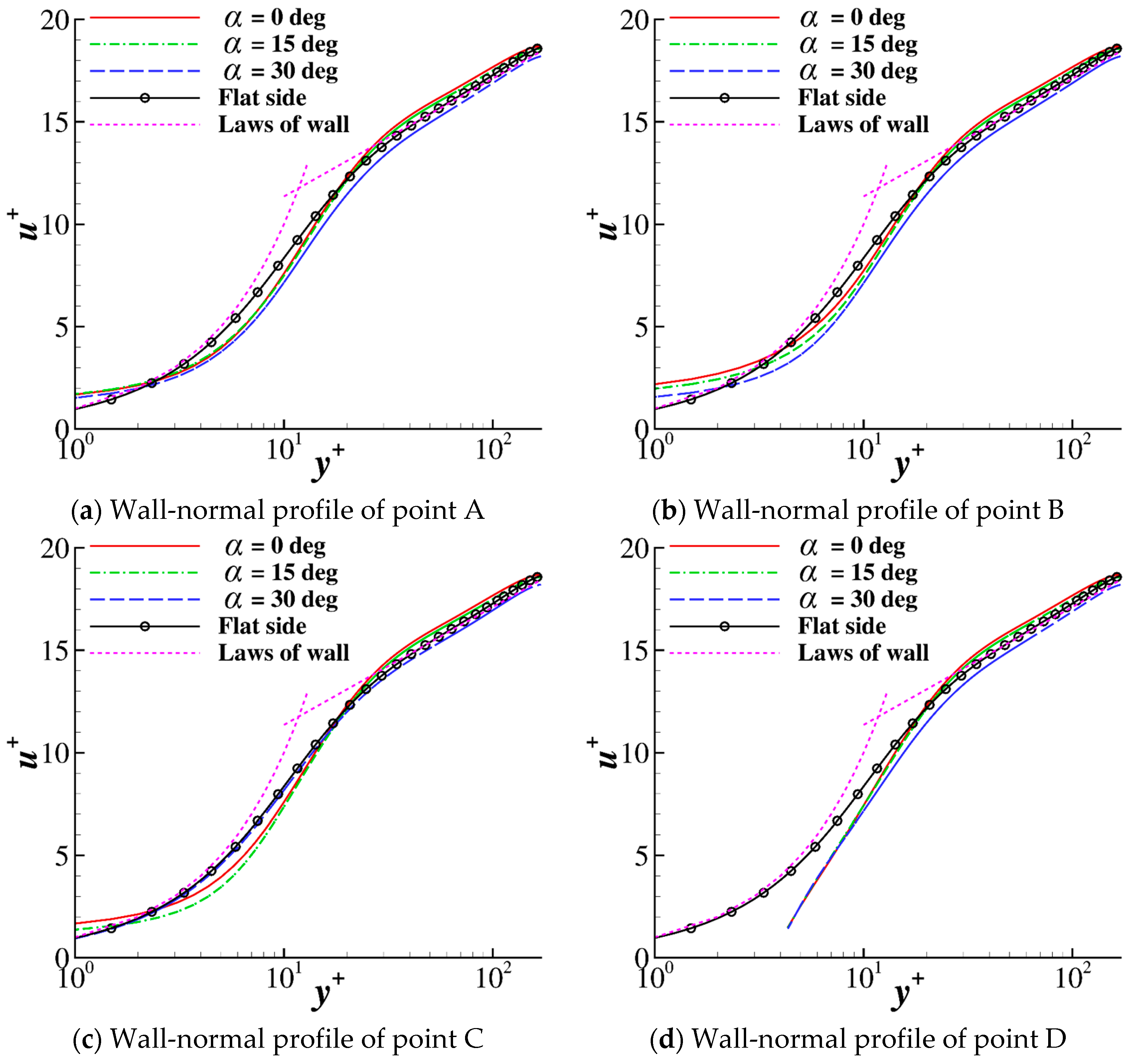
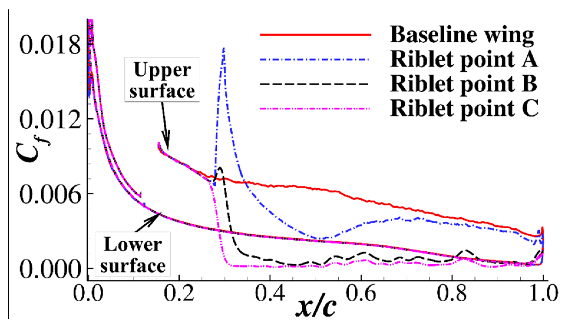
3.3. Flow Characteristics of the Riblets Covered Wing

Several streamwise locations were used to compare the flow quantities of the smooth and riblet-covered wings. The wall-normal profiles at these locations were sliced to study the effect of the riblets. Figure 13 shows pressure contour locations of the wall-normal profile. Table 3 provides the streamwise locations and the local flow angles of the smooth wing. The local flow angle was computed by the surface limiting streamline, as shown in Figure 9. The cross-flow directions of the front part and the aft part were opposite because of the pressure gradient on the wing. The cross-flow near the trailing edge was quite strong.
Figure 14 shows the wall-parallel velocity profiles at the seven locations. The smooth wing was denoted as the baseline profile. The profiles at the points A, B and C of Figure 7d are also presented. All the profiles were temporally and spatially averaged along the spanwise homogenous locations. The wall-parallel velocity U = u 2 + v 2 . The velocity profile of the riblets covered wing at x/c = 0.3 was similar to the smooth wing because it was the start location of the riblets. It was clear that the velocity gradient near the wall boundary was decreased by riblets at x/c ≥ 0.4, which led to a decrease in the wall friction. The largest reductions in the velocity gradient were at x/c = 0.4 and x/c = 0.5, where the pressure gradients were the strongest. This phenomenon agrees with previous airfoil computations [5]. The flow velocity of the outer part of the boundary layer near the trailing edge was increased by the riblets. A comparison of the velocity profiles extracted from the riblet tip (point A), middle (point B) and valley (point C) revealed that the profiles were different near the wall but coincided with each other away from the wall.
The cross-flow is a special flow phenomenon of a swept wing. Figure 15 presents the w velocity profile of the streamwise locations. The w velocity of the boundary layer was negative at x/c ≤ 0.5 but became positive at x/c ≥ 0.8. Regardless of whether the w velocity was negative or positive, the riblet film reduced the amplitude of the w velocity. The influence of riblet film was limited under Δy/c < 0.006 at x/c ≤ 0.5, while the efficient region increased near the trailing edge. Therefore, the riblet was a favorable cross flow suppression device, which may have been useful for improving the flow separation characteristics caused by cross-flow of a swept wing. Unlike the wall-parallel velocity, the w velocity profile was nearly the same for the riblet tip (point A), middle (point B) and valley (point C). The cross-flow near the wall was almost eliminated by the riblets. Consequently, the virtual origins of the cross-flow and streamwise flow boundary layers were different, which was in keeping with the protruding height theory of Luchini et al., [12].
The Reynolds stress components were also studied at the selected locations. Figure 16 shows the root mean square of the w velocity. This value is equal to the square root of the Reynolds normal stress w w ¯ . The wrms values of the 0° sweep and 30° sweep are both presented. In the figure, “sm” denotes the smooth cases, and “rib” denotes the riblet cases. The wrms values of the riblet middle location were plotted for the riblet cases. For the smooth cases, the wrms values of the 30° sweep case increased more rapidly than those of the 0° sweep case at the x/c = 0.3 and 0.4 locations. Beyond x/c = 0.6, the peak value of the 30° sweep case became lower than that of the 0° case. The riblets had a notable effect on the reduction of the Reynolds stress in both the 0° sweep and 30° sweep cases. The vertical locations of the peak values of the wrms were pushed away from the wall by the riblets. Thus, the stress near the wall was greatly reduced. At the locations near the trailing edge (x/c ≥ 0.8), the trends of the wrms variation caused by riblets at 0° sweep and 30° sweep were similar. Figure 17 shows the Reynolds stress u v ¯ , which was important for wall friction generation, at the seven streamwise locations. The variation trend of u v ¯ was similar to that of wrms. Even at the location of x/c = 0.97, where the local flow angle was 28.8°, the Reynolds stresses remained depressed by the riblets. This phenomenon differed from that of the yawed channel flow in Section 2 because the Reynolds stresses upstream of the wing were suppressed by the riblets. Consequently, although the wing had a moderate sweep angle and the cross-flow near the trailing edge was strong, the riblet film had a satisfactory effect on suppressing turbulence fluctuations.
Figure 18 shows the instantaneous streamwise vorticity contours of the smooth airfoil and the airfoil with riblets. The slices were located at x/c = 0.6. It was clear that the streamwise vortices of the smooth airfoil was more than the riblet covered airfoil. Moreover, the size of the riblets was smaller than the streamwise vortices, and the vortices were pushed away from the riblet surface.
Figure 19 shows the instantaneous iso-surface of Q-criterion Q(C/U)2 = 750. The iso-surfaces are colored by the nondimensional streamwise vorticity. It was clear that the turbulence structure emerged after the numerical trip location (x/c = 0.13) and then was considerably suppressed after the riblet-covered location (x/c = 0.3). The riblets demonstrated notable efficiency in reducing the vortex structures at the front part of the wing. However, the turbulence structures near the trailing edge for both smooth and riblet-covered wings were abundant. The turbulence control effect became weak near the trailing edge.

4. Conclusions

This paper studied the drag reduction effect of riblets when considering the sweep effect. A channel flow and an infinite swept wing were computationally investigated. The work can be summarized as follows:
(1) The channel flow case showed that the riblets could decrease the friction drag when the riblet direction was not parallel to the streamwise direction. However, the pressure drag increased rapidly with the inclined angle between the riblets and the flow direction. The present results showed that when the inclined angle was 15°, the drag reduction effect was satisfactory, while when the inclined angle was 30°, the riblets increased the drag. The velocity profiles and Reynolds stresses were also studied to analyze the drag reduction of riblets. The intercept of the log-law of the 30° case was decreased by the riblets, and the peak value of the Reynolds stresses was increased.
(2) An infinite wing with a 30° sweep angle was studied without and with a riblet film. The surface limiting streamlines were used to illustrate the local flow angle. The results demonstrated that the cross-flow was not strong over most parts of the swept wing except near the leading edge and the trailing edge of the wing. The riblet film showed a considerable drag reduction effect on the swept wing. Similar to the channel flow case, the friction drag was reduced and the pressure drag was increased. The lift and friction drag followed the cosine law of a swept wing, while the pressure drag did not follow the cosine law. Analysis of the velocity profiles and Reynolds stresses showed that the riblets had a good effect on suppressing cross flow and reducing turbulence fluctuations.

Author Contributions

Conceptualization, Formal Analysis, Writing–Review & Editing, Y.Z.; Methodology, Software, Data Curation, Y.Y.

Funding

This work was supported by the National Natural Science Foundation of China (11872230 and 91852108), the National Key Basic Research Program of China (2014CB744801) and the Key Laboratory of Aerodynamic Noise Control (grant No. ANCL20180106).

Conflicts of Interest

The authors declare that they have no conflicts of interest with regard to this work.

References

  1. Strang, W.J.; Mckinlay, R.M. Concorde in service. Aeronaut. J. 1979, 83, 39–52. [Google Scholar]
  2. Van Dam, C. Recent experience with different methods of drag prediction. Prog. Aerosp. Sci. 1999, 35, 751–798. [Google Scholar] [CrossRef]
  3. Heinemann, P.; Panagiotou, P.; Vratny, P.; Kaiser, S.; Hornung, M.; Yakinthos, K. Advanced Tube and Wing Aircraft for Year 2050 Timeframe. In Proceedings of the 55th AIAA Aerospace Sciences Meeting, Grapevine, TX, USA, 9–13 January 2017. AIAA Paper 2017-1390. [Google Scholar]
  4. Yamazaki, W.; Matsushima, K.; Nakahashi, K. Drag Decomposition-Based Adaptive Mesh Refinement. J. Aircr. 2007, 44, 1896–1905. [Google Scholar] [CrossRef]
  5. Zhang, Y.; Chen, H.; Fu, S.; Dong, W. Numerical study of an airfoil with riblets installed based on large eddy simulation. Aerosp. Sci. Technol. 2018, 78, 661–670. [Google Scholar] [CrossRef]
  6. McLean, J.D.; George-Falvy, D.N.; Sullivan, P.P. Flight-test of turbulent skin-friction reduction by riblets. In Proceedings of the International Conference on Turbulent Drag Reduction by Passive Means, London, UK, 15–17 September 1987. [Google Scholar]
  7. Dean, B.; Bhushan, B. Shark-skin surfaces for fluid-drag reduction in turbulent flow: A review. Philos. Trans. R. Soc. A 2012, 368, 4775–4806. [Google Scholar] [CrossRef] [PubMed]
  8. Bechert, D.W.; Bruse, M.; Hage, W.; Meyer, R. Fluid Mechanics of Biological Surfaces and their Technological Application. Naturwissenschaften 2000, 87, 157–171. [Google Scholar] [CrossRef] [PubMed]
  9. Walsh, M.J. Riblets as a Viscous Drag Reduction Technique. AIAA J. 1983, 21, 485–486. [Google Scholar] [CrossRef]
  10. Choi, H.; Moin, P.; Kim, J. Direct numerical simulation of turbulent flow over riblets. J. Fluid Mech. 1993, 255, 503. [Google Scholar] [CrossRef]
  11. Bechert, D.W.; Bartenwerfer, M. The viscous flow on surfaces with longitudinal ribs. J. Fluid Mech. 1989, 206, 105. [Google Scholar] [CrossRef]
  12. Luchini, P.; Manzo, F.; Pozzi, A. Resistance of a grooved surface to parallel flow and cross-flow. J. Fluid Mech. Digit. Arch. 1991, 228, 87. [Google Scholar] [CrossRef]
  13. Bechert, D.W.; Bruse, M.; Hage, W.; Van Der Hoeven, J.G.T.; Hoppe, G. Experiments on drag-reducing surfaces and their optimization with an adjustable geometry. J. Fluid Mech. 1997, 338, 59–87. [Google Scholar] [CrossRef]
  14. Goldstein, D.; Handler, R.; Sirovich, L. Direct numerical simulation of turbulent flow over a modeled riblet covered surface. J. Fluid Mech. 1995, 302, 333. [Google Scholar] [CrossRef]
  15. Krieger, V.; Perić, R.; Jovanović, J.; Lienhart, H.; Delgado, A. Toward design of the antiturbulence surface exhibiting maximum drag reduction effect. J. Fluid Mech. 2018, 850, 262–303. [Google Scholar] [CrossRef] [Green Version]
  16. Strand, J.S.; Goldstein, D.B. Direct numerical simulations of riblets to constrain the growth of turbulent spots. J. Fluid Mech. 2011, 668, 267–292. [Google Scholar] [CrossRef] [Green Version]
  17. Walsh, M.J.; Lindemann, A.M. Optimization and Application of Riblets for Turbulent Drag Reduction. In Proceedings of the 22nd Aerospace Sciences Meeting, Reno, NV, USA, 9–12 January 1984. AIAA Paper 1984-0347. [Google Scholar]
  18. Saravi, S.S.; Cheng, K. A review of drag reduction by riblets and micro-textures in the turbulent boundary layers. Eur. Sci. J. 2013, 33, 62–81. [Google Scholar]
  19. Viswanath, P.R. Aircraft viscous drag reduction using riblets. Prog. Aerosp. Sci. 2002, 38, 571–600. [Google Scholar] [CrossRef] [Green Version]
  20. Sundaram, S.; Viswanath, P.R.; Subaschandar, N. Viscous drag reduction using riblets on a swept wing. AIAA J. 1999, 37, 851–856. [Google Scholar] [CrossRef]
  21. Benschop, H.; Breugem, W.-P. Drag reduction by herringbone riblet texture in direct numerical simulations of turbulent channel flow. J. Turbul. 2017, 18, 717–759. [Google Scholar] [CrossRef]
  22. Peet, Y.; Sagaut, P.; Charron, Y. Pressure loss reduction in hydrogen pipelines by surface restructuring. Int. J. Hydrog. Energy 2009, 34, 8964–8973. [Google Scholar] [CrossRef]
  23. Ghebali, S.; Chernyshenko, S.I.; Leschziner, M.A. Can large-scale oblique undulations on a solid wall reduce the turbulent drag? Phys. Fluids 2017, 29, 105102. [Google Scholar] [CrossRef] [Green Version]
  24. Kramer, F.; Gruneberger, R.; Thiele, F.H.; Wassen, E. Wavy riblets for turbulent drag reduction. In Proceedings of the 5th Flow Control Conference, Chicago, IL, USA, 28 June–1 July, 2010. AIAA Paper 2010-4583. [Google Scholar]
  25. Chen, H.; Rao, F.; Shang, X.; Zhang, D.; Hagiwara, I. Biomimetic Drag Reduction Study on Herringbone Riblets of Bird Feather. J. Bionic Eng. 2013, 10, 341–349. [Google Scholar] [CrossRef]
  26. Lyon, C.A.; Selig, M.S.; Broeren, A.P. Boundary layer trips on airfoils at low Reynolds numbers. In Proceedings of the 35th Aerospace Sciences Meeting and Exhibit, Reno, NV, USA, 6–9 January 1997. AIAA Paper 19970–511. [Google Scholar]
  27. Li, Z.; Zhang, Y.; Chen, H. A low dissipation numerical scheme for Implicit Large Eddy Simulation. Comput. Fluids 2015, 117, 233–246. [Google Scholar] [CrossRef]
  28. Aupoix, B.; Pailhas, G.; Houdeville, R. Towards a General Strategy to Model Riblet Effects. AIAA J. 2012, 50, 708–716. [Google Scholar] [CrossRef]
  29. Zhao, T.; Zhang, Y.; Chen, H.; Chen, Y.; Zhang, M. Supercritical wing design based on airfoil optimization and 2.75D transformation. Aerosp. Sci. Technol. 2016, 56, 168–182. [Google Scholar] [CrossRef]
Figure 1. Sketch map of the blade-type riblets and the grid near the riblets.
Energies 12 03386 g001aEnergies 12 03386 g001b
Figure 2. Wall-normal Δy+ and spanwise Δz+ on the riblet side.
Energies 12 03386 g002
Figure 3. Histories of the drag coefficient for the α = 0° case.
Energies 12 03386 g003
Figure 4. Mean streamwise velocity distributions at several wall-normal profile lines.
Energies 12 03386 g004
Figure 5. Root mean squares of the velocities and the Reynolds shear stresses of the channel.
Energies 12 03386 g005
Figure 6. Iso-surface of the Q-criterion Q(δ/U)2 = 1 (colored by the streamwise velocity).
Energies 12 03386 g006aEnergies 12 03386 g006b
Figure 7. Riblet configuration and computational grid.
Energies 12 03386 g007aEnergies 12 03386 g007b
Figure 8. Spanwise autocorrelation at several streamwise locations.
Energies 12 03386 g008
Figure 9. Averaged surface streamlines of the smooth wing.
Energies 12 03386 g009
Figure 10. Aerodynamic force histories of the smooth wing and the wing with riblets.
Energies 12 03386 g010aEnergies 12 03386 g010b
Figure 11. Averaged pressure coefficients of the smooth and riblet-covered wing with and without a sweep angle.
Energies 12 03386 g011
Figure 12. Skin friction coefficient of the wing without and with riblets.
Energies 12 03386 g012
Figure 13. Pressure coefficient contour and streamwise locations.
Energies 12 03386 g013
Figure 14. Wall-parallel velocity profiles at the seven streamwise locations.
Energies 12 03386 g014
Figure 15. w velocity profiles of the seven streamwise locations.
Energies 12 03386 g015
Figure 16. Root mean square of w velocity at the seven locations.
Energies 12 03386 g016
Figure 17. Reynolds stress u v ¯ at the seven locations.
Energies 12 03386 g017
Figure 18. Instantaneous streamwise vorticity contours at x/c = 0.6.
Energies 12 03386 g018
Figure 19. Instantaneous iso-surface of Q-criterion Q(C/U)2 = 750 (colored by the nondimensional streamwise vorticity).
Energies 12 03386 g019
Table 1. Drag coefficients of the channels with different inclined angles between the riblets and the main flow direction.
Riblets Angle αFlat Side Friction Drag CD,f or Total Drag CDRiblets Side Friction Drag CD,fRiblets Side Pressure Drag CD,pRiblets Side Total Drag CDDrag Reduction (%)
0.008200.007560.000000.007567.8%
15°0.008240.007110.000600.007716.4%
30°0.008260.006060.002470.00853−3.3%
Table 2. Averaged force coefficients of the wing without and with riblets.
Computation MethodConfigurationLift CoefficientTotal DragPressure DragFriction Drag
Present computationSmooth wing0.38120.012300.003240.00906
Wing with riblets0.40180.011240.004000.00724
Variation (%)5.40%–8.49%23.81%20.03%
Estimated from 0° sweep [5]Smooth wing0.40430.010990.002310.00868
Wing with riblets0.41630.009960.002910.00705
Variation (%)2.96%–9.37%25.97%18.77%
Table 3. Streamwise locations and local flow angles.
x/cLocal Flow Angle (°)
0.3–5.7
0.4–3.7
0.5–0.3
0.64.2
0.811.9
0.917.5
0.9728.8

