A Nonlinear-Model-Based Observer for a State-of-Charge Estimation of a Lithium-Ion Battery in Electric Vehicles


Abstract
:1. Introduction
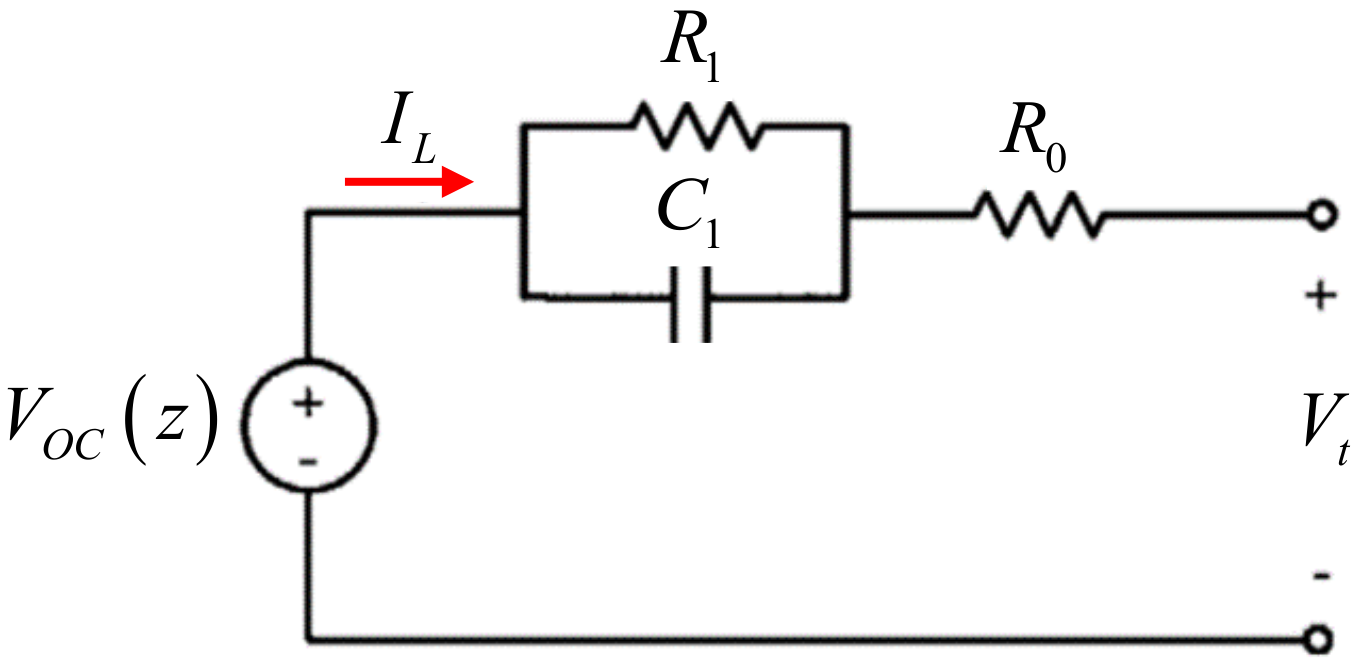
2. Nonlinear System Model for a Single Battery Cell
2.1. Linearized System Model for a Single Battery Cell
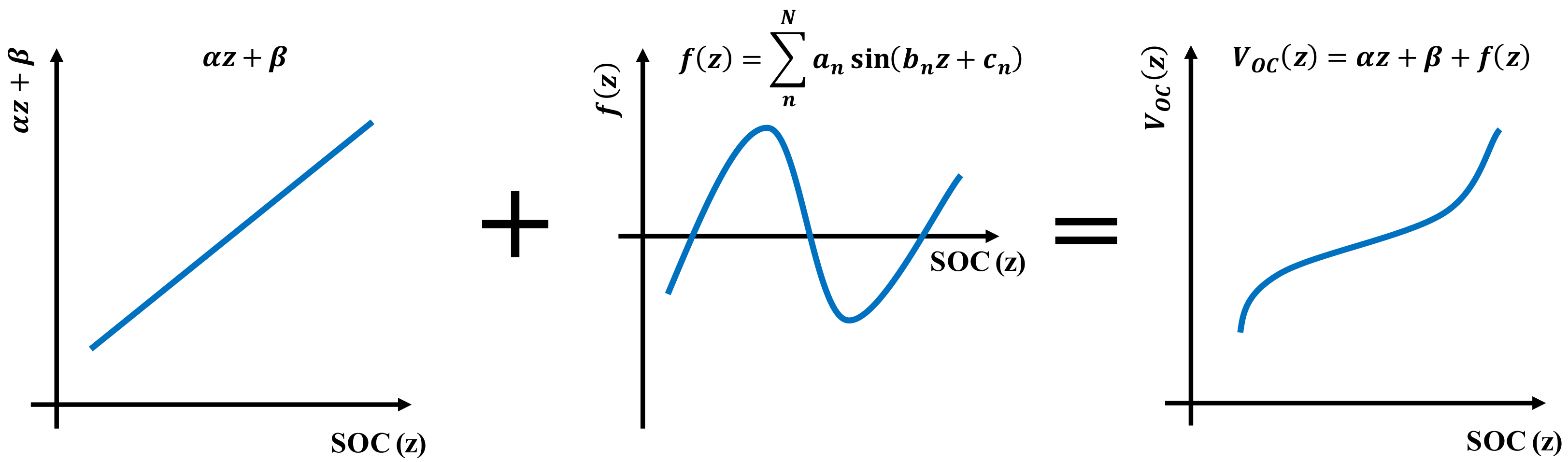
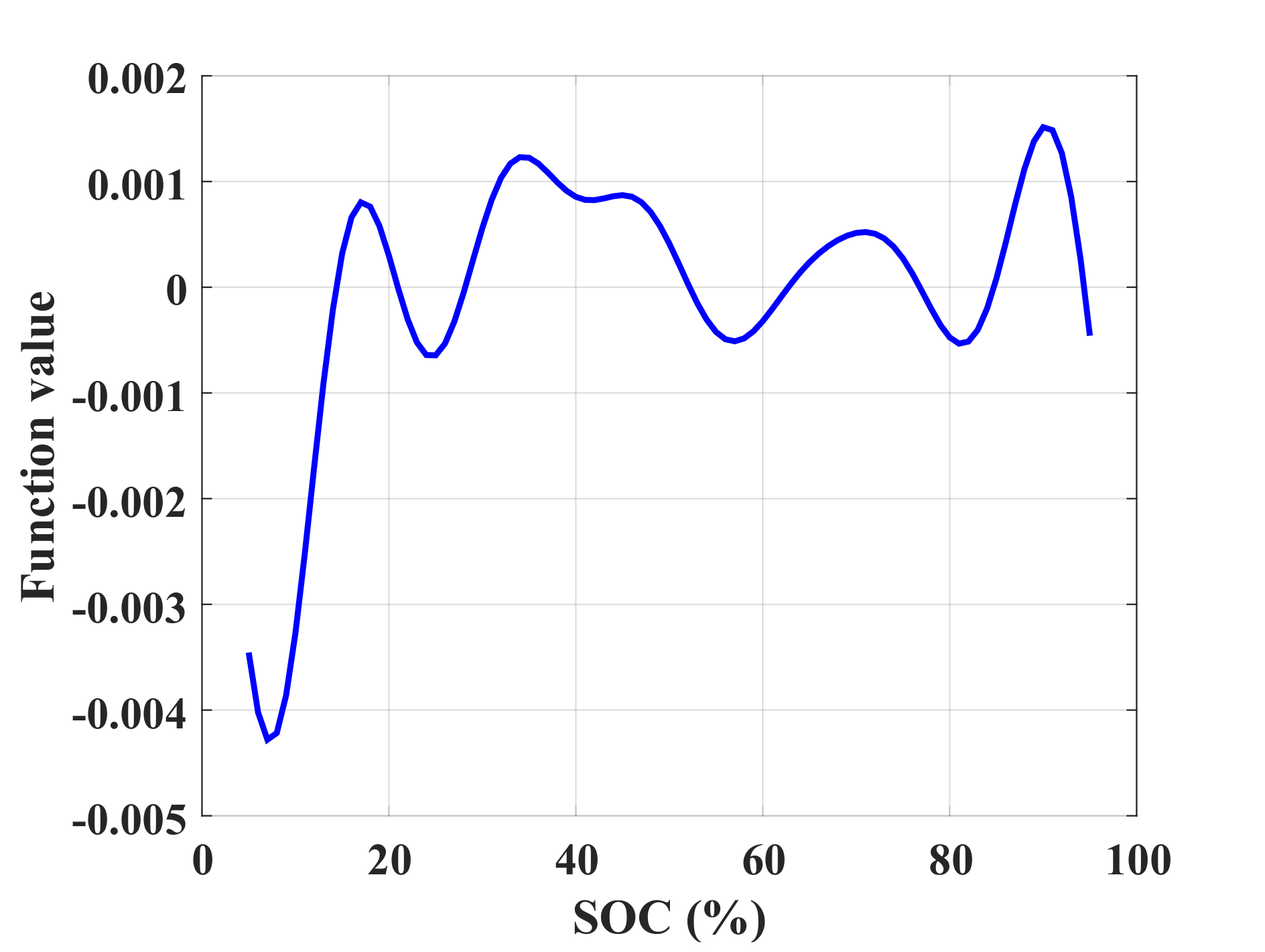
2.2. Nonlinear System Model for a Single Battery Cell
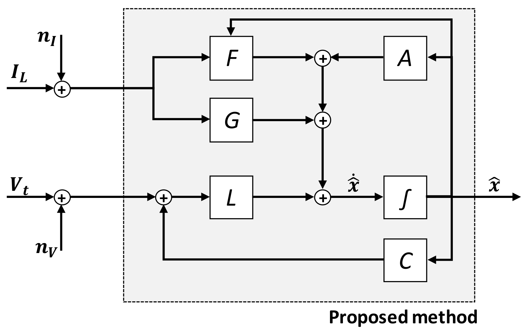
3. Nonlinear-Model-Based Observer Design
4. Experiments
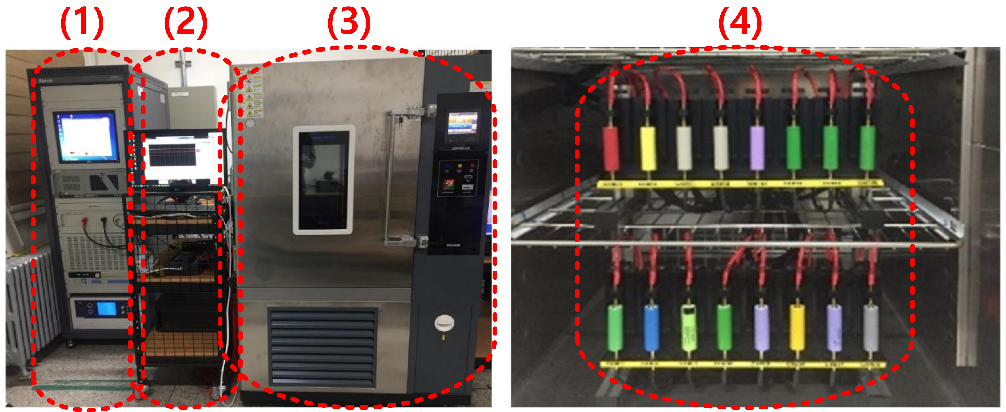
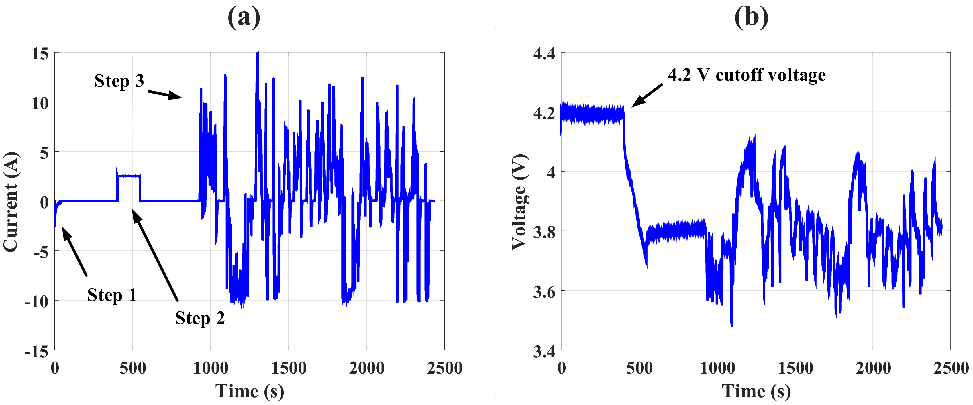
4.1. Experimental Setup
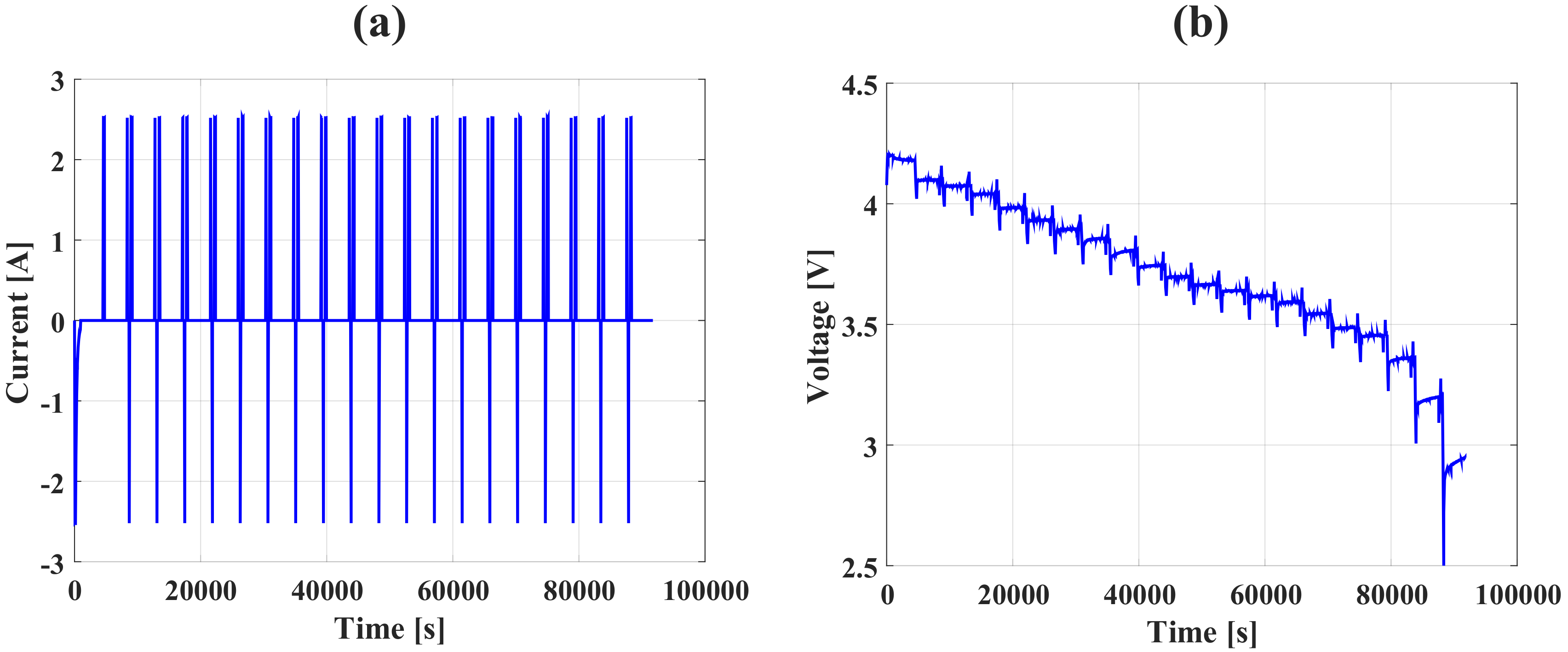
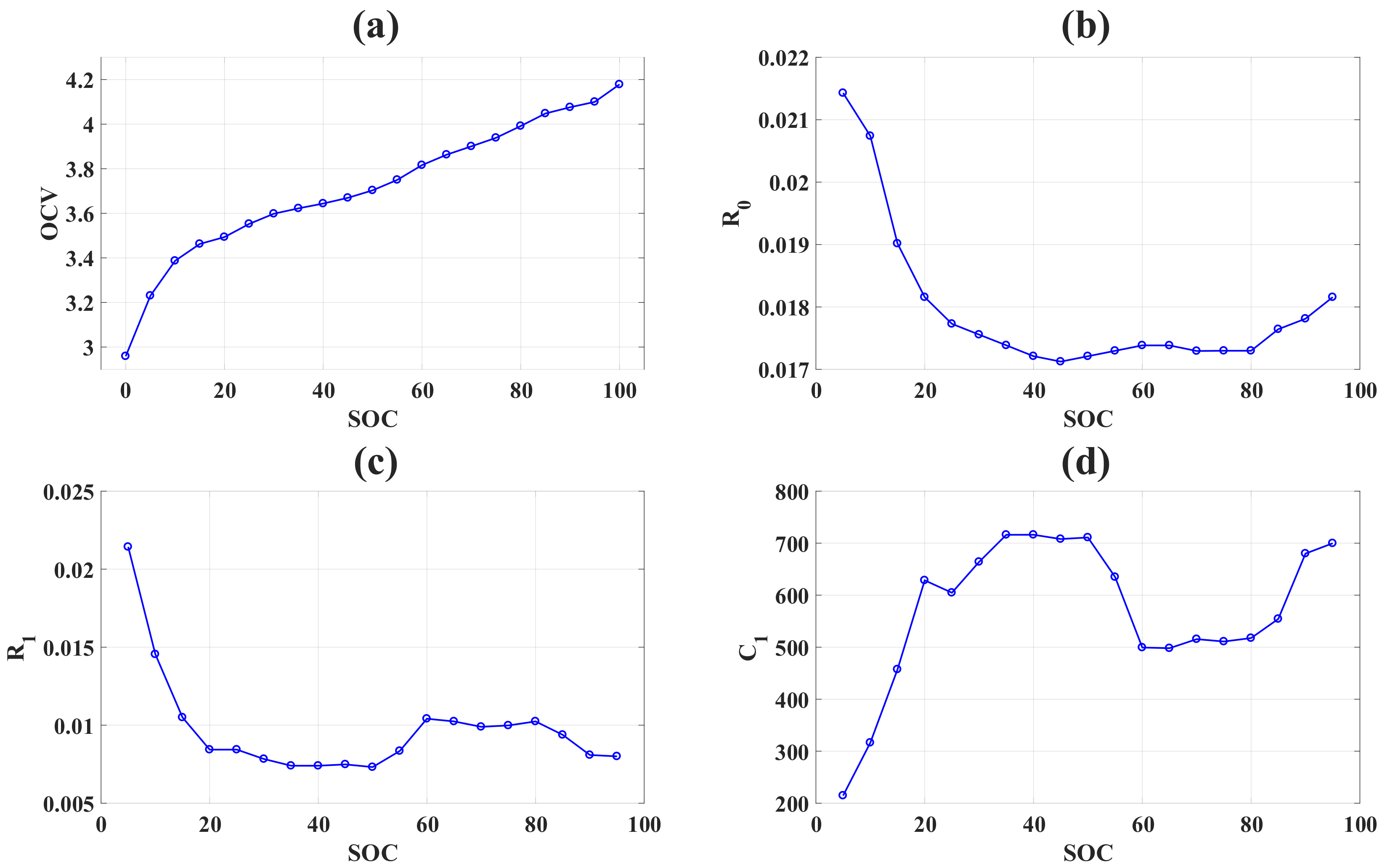
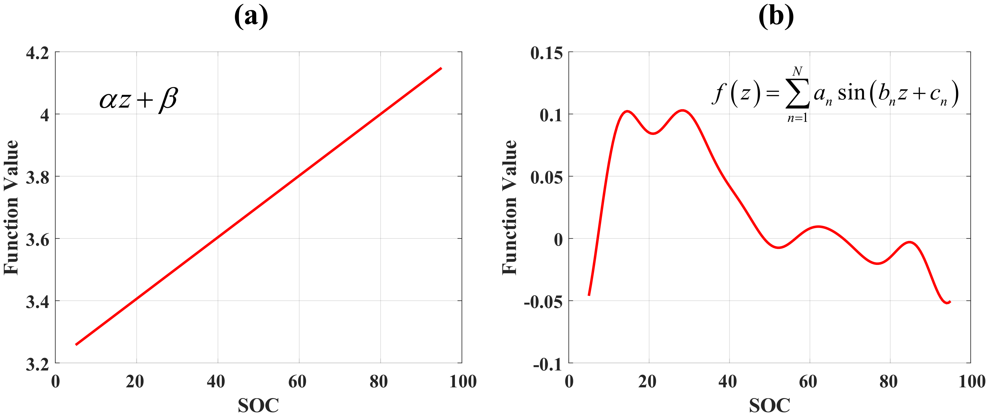
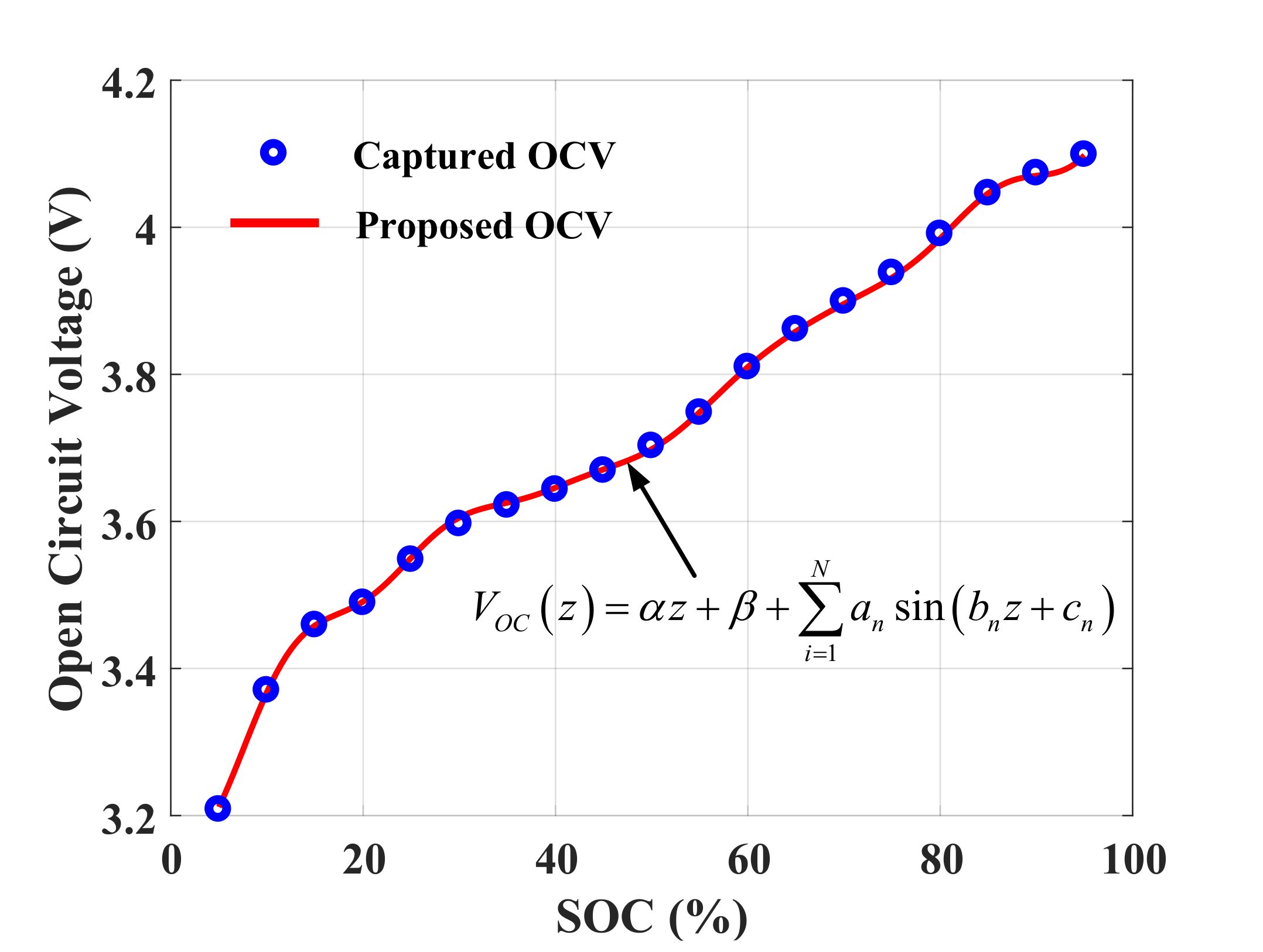
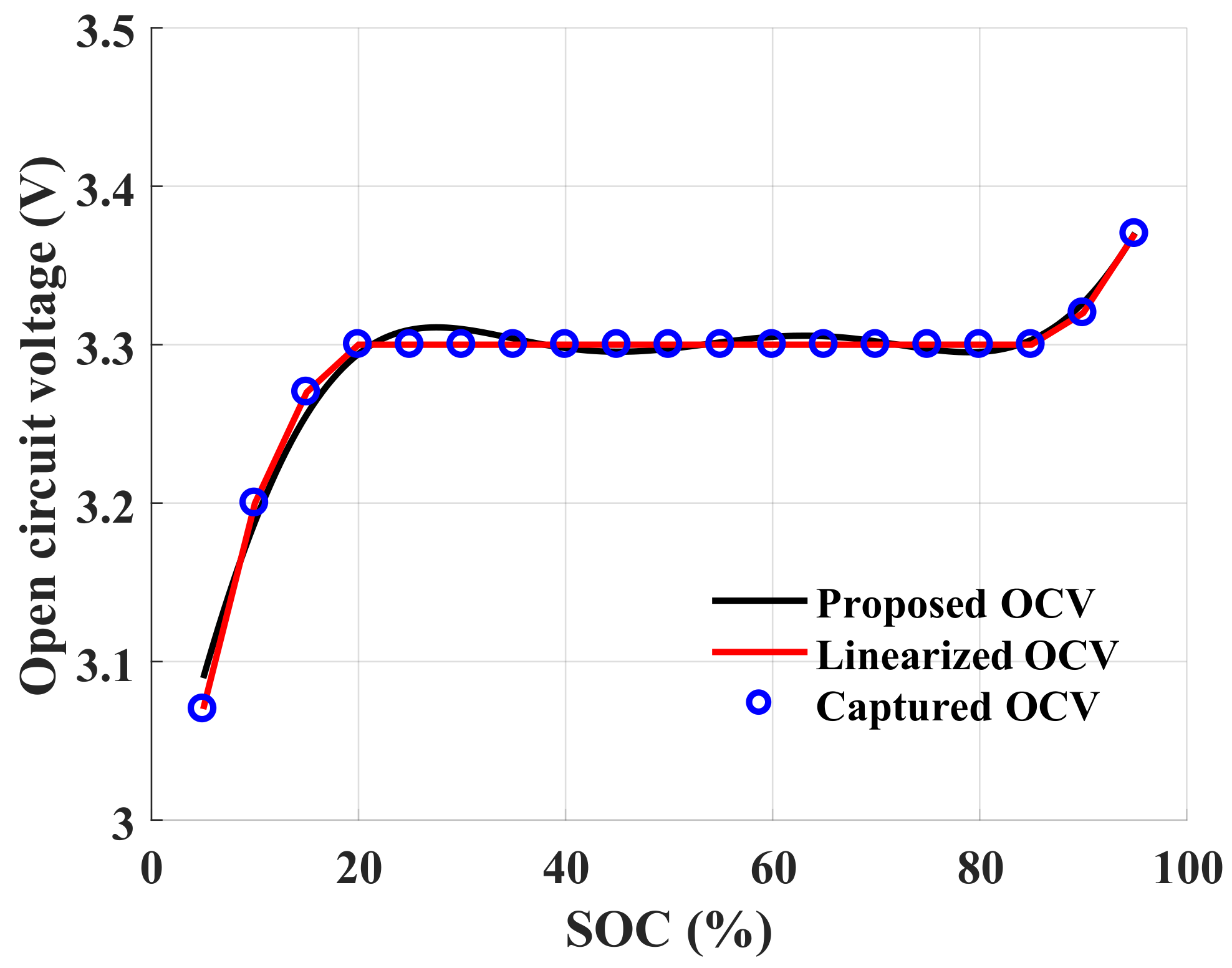
4.2. Target Battery Specification and Parameters Extraction
4.3. Experimental Results
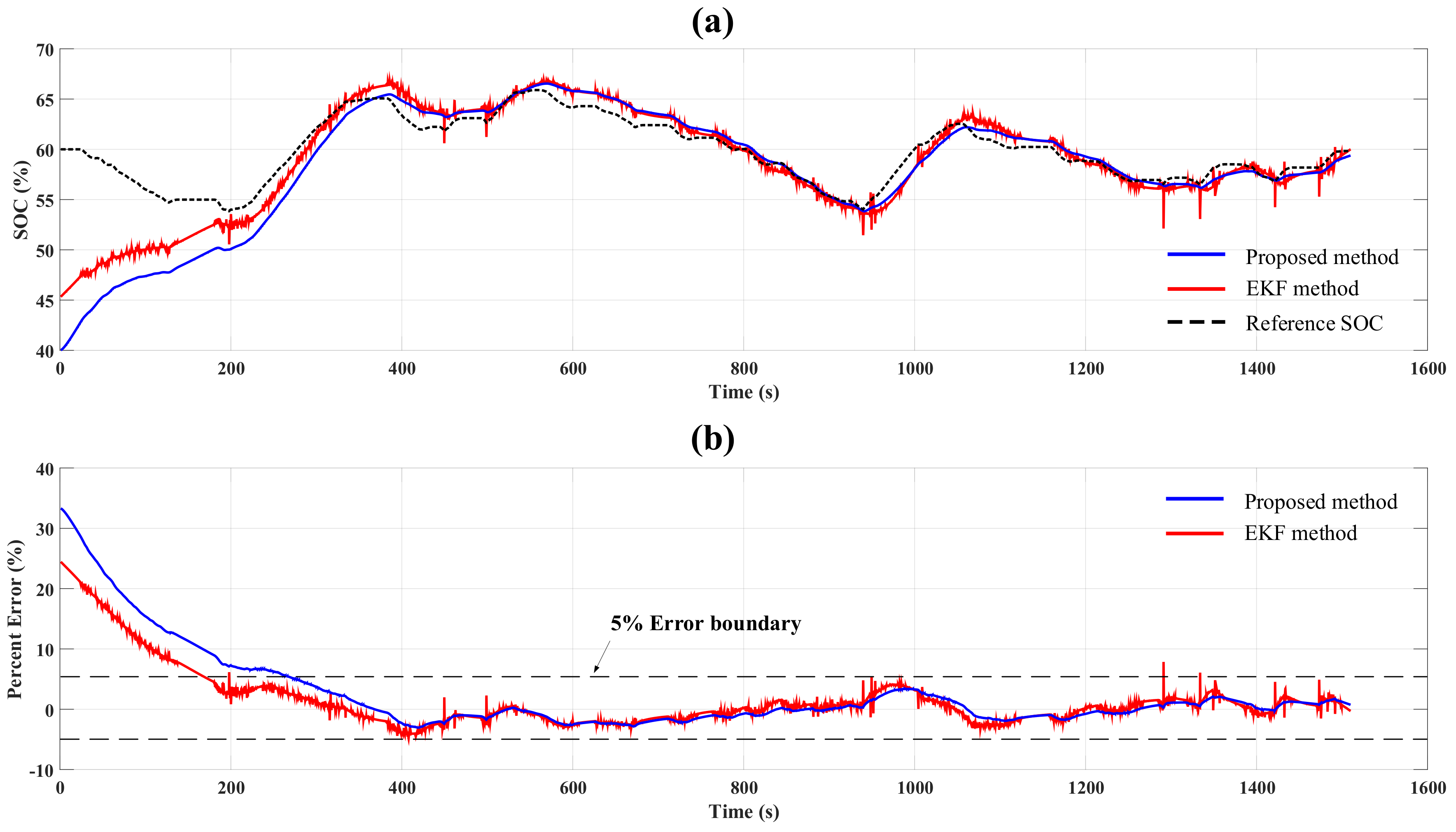
4.3.1. Case 1: Noiseless Condition
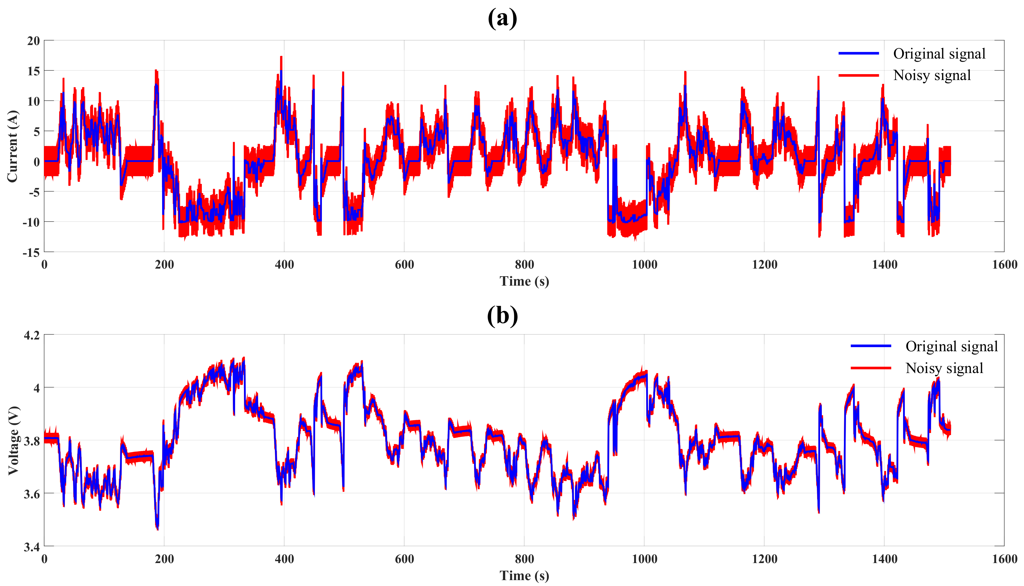
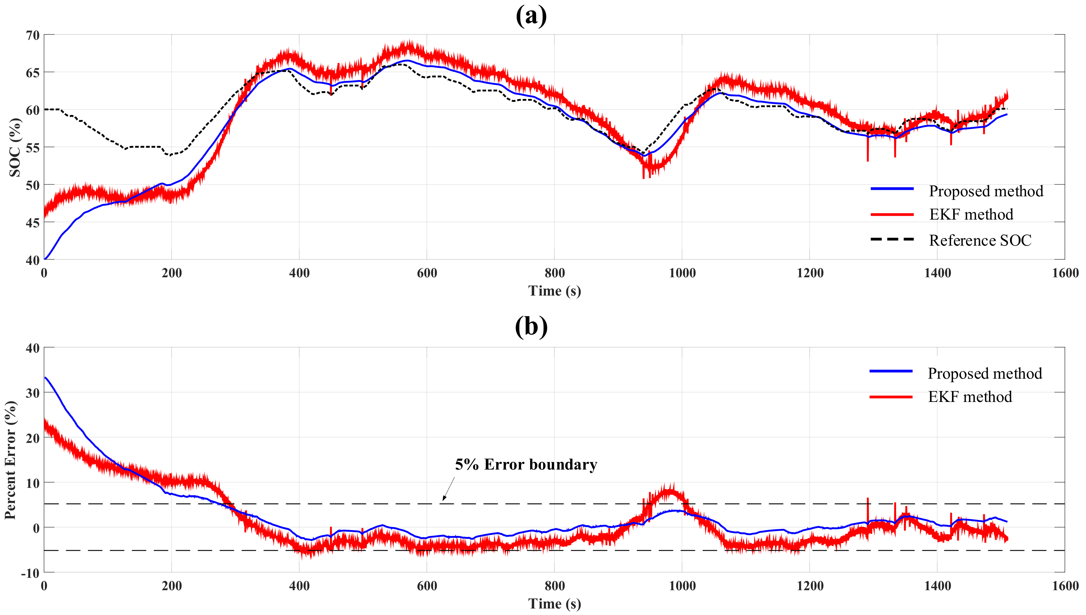
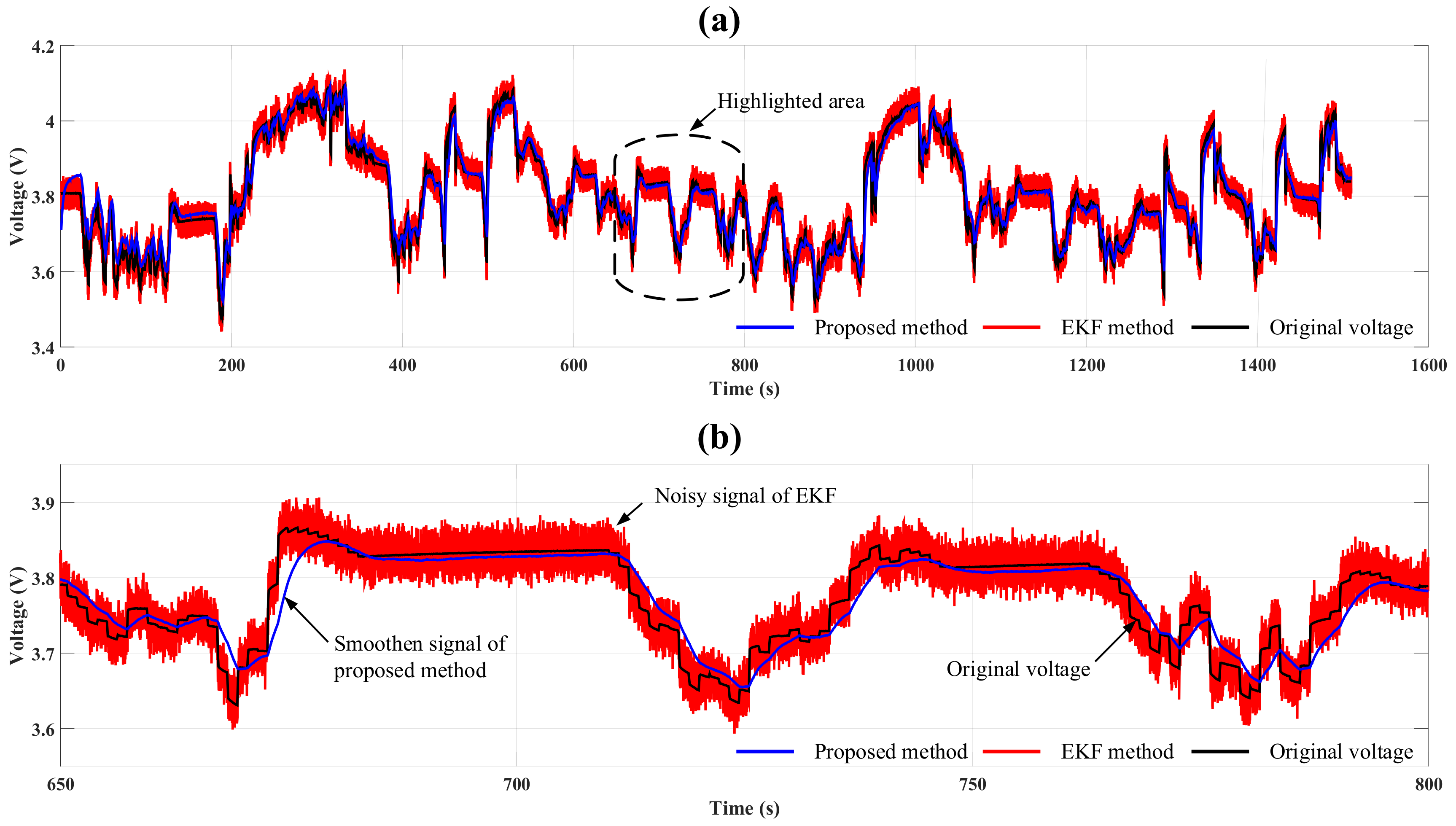
4.3.2. Case 2: Voltage Sensor Noise Condition
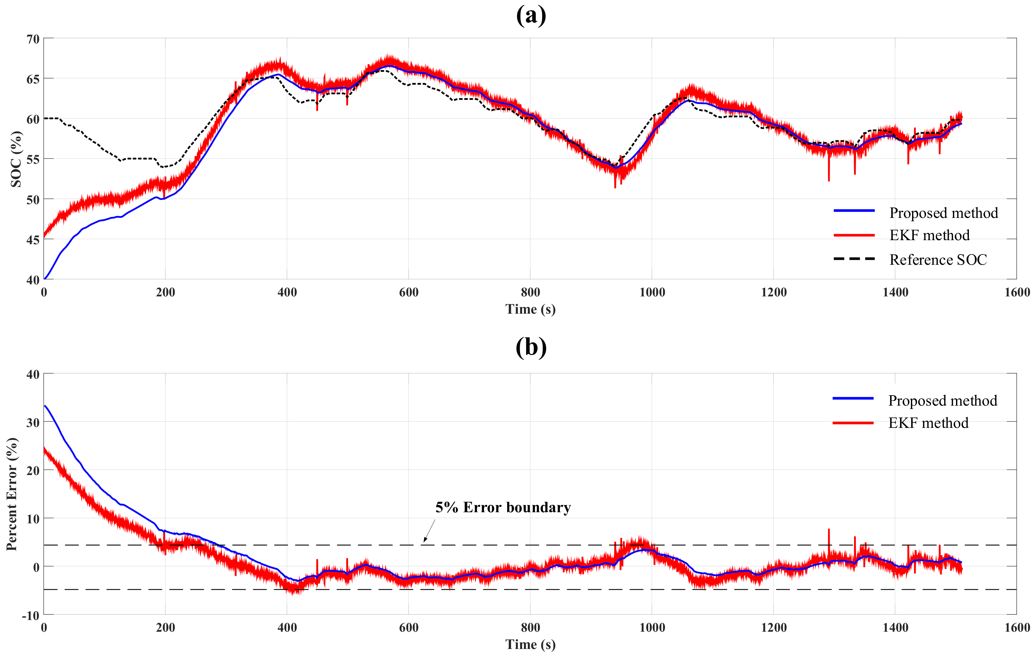
4.3.3. Case 3: Voltage and Current Sensor Noise Condition
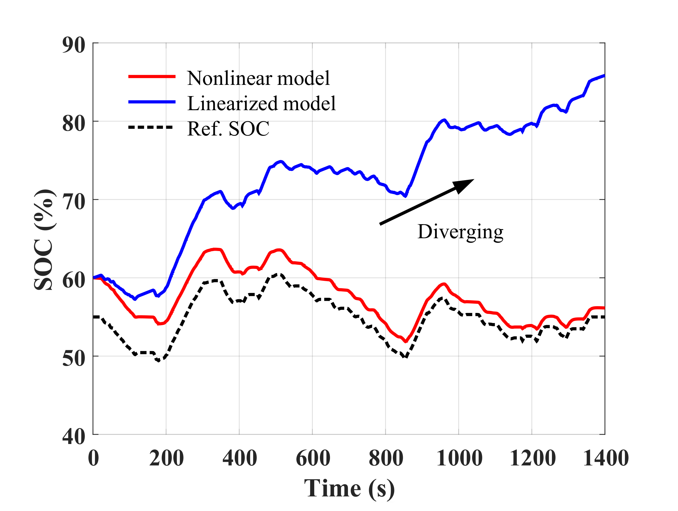
5. Discussion
Simulation Study with a Virtual Battery Cell Having Wide Range of Flat OCV Curve
6. Conclusions
Author Contributions
Funding
Conflicts of Interest
Abbreviations
| HEV | Hybrid electric vehicle |
| EV | Electric vehicle |
| BMS | Battery management system |
| Li-ion | Lithium-ion |
| SOC | State of charge |
| ANN | Artificial neural network |
| EECM | Equivalent Electrochemical model |
| ECM | Equivalent circuit model |
| OCV | Open-circuit voltage |
| HPPC | Hybrid pulse power characterization |
| UDDS | Urban dynamometer driving schedule |
| MAE | Mean absolute error |
| LFP | LiFePO4; Lithium-ion phosphate battery |
| EKF | Extended Kalman filter |
References
- Zhou, L.; Zheng, Y.; Ouyang, M.; Lu, L. A study on parameter variation effects on battery packs for electric vehicles. J. Power Sources 2017, 364, 242–252. [Google Scholar] [CrossRef]
- He, H.; Qin, H.; Sun, X.; Shui, Y. Comparison Study on the Battery SoC Estimation with EKF and UKF Algorithms. Energies 2013, 6, 5088–5100. [Google Scholar] [CrossRef]
- Rezvanizaniani, S.M.; Liu, Z.; Chen, Y.; Lee, J. Review and recent advances in battery health monitoring and prognostics technologies for electric vehicle (EV) safety and mobility. J. Power Sources 2014, 256, 110–124. [Google Scholar] [CrossRef]
- Lu, L.; Han, X.; Li, J.; Hua, J.; Ouyang, M. A review on the key issues for lithium-ion battery management in electric vehicles. J. Power Sources 2013, 226, 272–288. [Google Scholar] [CrossRef]
- Hannan, M.A.; Lipu, M.S.H.; Hussain, A.; Mohamed, A. A review of lithium-ion battery state of charge estimation and management system in electric vehicle applications: Challenges and recommendations. Renew. Sustain. Energy Rev. 2017, 78, 834–854. [Google Scholar] [CrossRef]
- Ali, M.U.; Zafar, A.; Nengroo, S.H.; Hussain, S.; Alvi, M.J.; Kim, H.J. Towards a Smarter Battery Management System for Electric Vehicle Applications: A Critical Review of Lithium-Ion Battery State of Charge Estimation. Energies 2019, 12, 446. [Google Scholar] [CrossRef]
- Hoque, M.M.; Hannan, M.A.; Mohamed, A.; Ayob, A. Battery charge equalization controller in electric vehicle applications: A review. Renew. Sustain. Energy Rev. 2017, 75, 1363–1385. [Google Scholar] [CrossRef]
- Nitta, N.; Wu, F.; Lee, J.T.; Yushin, G. Li-ion battery materials: Present and future. Mater. Today 2015, 18, 252–264. [Google Scholar] [CrossRef]
- He, W.; Williard, N.; Chen, C.; Pecht, M. State of charge estimation for electric vehicle batteries using unscented kalman filtering. Microelectron. Reliab. 2013, 53, 840–847. [Google Scholar] [CrossRef]
- Xia, B.; Wang, H.; Tian, Y.; Wang, M.; Sun, W.; Xu, Z. State of Charge Estimation of Lithium-Ion Batteries Using an Adaptive Cubature Kalman Filter. Energies 2015, 8, 5916–5936. [Google Scholar] [CrossRef] [Green Version]
- Fang, Q.; Wei, X.; Dai, H. A Remaining Discharge Energy Prediction Method for Lithium-Ion Battery Pack Considering SOC and Parameter Inconsistency. Energies 2019, 12, 987. [Google Scholar] [CrossRef]
- Yang, N.; Zhang, X.; Li, G. State of charge estimation for pulse discharge of a LiFePO4 battery by a revised Ah counting. Electrochim. Acta 2015, 151, 63–71. [Google Scholar] [CrossRef]
- Ng, K.S.; Moo, C.S.; Chen, Y.P.; Hsieh, Y.C. Enhanced coulomb counting method for estimating state-of-charge and state-of-health of lithium-ion batteries. Appl. Energy 2009, 86, 1506–1511. [Google Scholar] [CrossRef]
- Weigert, T.; Tian, Q.; Lian, K. State-of-charge prediction of batteries and battery–supercapacitor hybrids using artificial neural networks. J. Power Sources 2011, 196, 4061–4066. [Google Scholar] [CrossRef]
- Shen, Y. Adaptive online state-of-charge determination based on neuro-controller and neural network. Energy Convers. Manag. 2010, 51, 1093–1098. [Google Scholar] [CrossRef]
- Lai, X.; Qiao, D.; Zheng, Y.; Zhou, L. A Fuzzy State-of-Charge Estimation Algorithm Combining Ampere-Hour and an Extended Kalman Filter for Li-Ion Batteries Based on Multi-Model Global Identification. Appl. Sci. 2018, 8, 2028. [Google Scholar] [CrossRef]
- Plett, G.L. Battery Management Systems, Volume I: Battery Modeling; Artech House: Norwood, MA, USA, 2015. [Google Scholar]
- Nikolian, A.; Hoog, J.D.; Fleurbay, K.; Timmermans, J.M.; Noshin, O.; Bossche, P.V.D.; Mierlo, J.V. Classification of Electric modelling and Characterization methods of Lithium-ion Batteries for Vehicle Applications. In Proceedings of the European Electric Vehicle Congress, Brussels, Belgium, 2–5 December 2014; pp. 1–15. [Google Scholar]
- Nikolian, A.; Firouz, Y.; Gopalakrishnan, R.; Timmermans, J.M.; Omar, N.; van den Bossche, P.; van Mierlo, J. Lithium Ion Batteries—Development of Advanced Electrical Equivalent Circuit Models for Nickel Manganese Cobalt Lithium-Ion. Energies 2016, 9, 360. [Google Scholar] [CrossRef]
- Lee, S.; Kim, J.; Lee, J.; Cho, B.H. State-of-charge and capacity estimation of lithium-ion battery using a new open-circuit voltage versus state-of-charge. J. Power Sources 2008, 185, 1367–1373. [Google Scholar] [CrossRef]
- Nejad, S.; Gladwin, D.T.; Stone, D.A. A systematic review of lumped-parameter equivalent circuit models for real-time estimation of lithium-ion battery states. J. Power Sources 2016, 316, 183–196. [Google Scholar] [CrossRef] [Green Version]
- He, H.; Xiong, R.; Fan, J. Evaluation of Lithium-Ion Battery Equivalent Circuit Models for State of Charge Estimation by an Experimental Approach. Energies 2011, 4, 582–598. [Google Scholar] [CrossRef]
- Sun, Q.; Zhang, H.; Zhang, J.; Ma, W. Adaptive Unscented Kalman Filter with Correntropy Loss for Robust State of Charge Estimation of Lithium-Ion Battery. Energies 2018, 11, 123. [Google Scholar] [CrossRef]
- Jung, S.; Jeong, H. Extended Kalman Filter-Based State of Charge and State of Power Estimation Algorithm for Unmanned Aerial Vehicle Li-Po Battery Packs. Energies 2017, 10, 237. [Google Scholar] [CrossRef]
- Diab, Y.; Auger, F.; Schaeffer, E.; Wahbeh, M. Estimating Lithium-Ion Battery State of Charge and Parameters Using a Continuous-Discrete Extended Kalman Filter. Energies 2017, 10, 75. [Google Scholar] [CrossRef]
- Yu, Z.; Huai, R.; Xiao, L. State-of-Charge Estimation for Lithium-Ion Batteries Using a Kalman Filter Based on Local Linearization. Energies 2015, 8, 7854–7873. [Google Scholar] [CrossRef] [Green Version]
- He, Z.; Gao, M.; Wang, C.; Wang, L.; Liu, Y. Adaptive State of Charge Estimation for Li-Ion Batteries Based on an Unscented Kalman Filter with an Enhanced Battery Model. Energies 2013, 6, 4134–4151. [Google Scholar] [CrossRef] [Green Version]
- Hu, X.; Sun, F.; Zou, Y. Estimation of State of Charge of a Lithium-Ion Battery Pack for Electric Vehicles Using an Adaptive Luenberger Observer. Energies 2010, 3, 1586–1603. [Google Scholar] [CrossRef]
- Tian, Y.; Chen, C.; Xia, B.; Sun, W.; Xu, Z.; Zheng, W. An Adaptive Gain Nonlinear Observer for State of Charge Estimation of Lithium-Ion Batteries in Electric Vehicles. Energies 2014, 7, 5995–6012. [Google Scholar] [CrossRef]
- Kim, I.S. The novel state of charge estimation method for lithium battery using sliding mode observer. J. Power Sources 2006, 163, 584–590. [Google Scholar] [CrossRef]
- Kim, D.; Koo, K.; Jeong, J.; Goh, T.; Kim, S. Second-Order Discrete-Time Sliding Mode Observer for State of Charge Determination Based on a Dynamic Resistance Li-Ion Battery Model. Energies 2013, 6, 5538–5551. [Google Scholar] [CrossRef] [Green Version]
- Chen, X.; Shen, W.; Cao, Z.; Kapoor, A. A novel approach for state of charge estimation based on adaptive switching gain sliding mode observer in electric vehicles. J. Power Sources 2014, 246, 667–678. [Google Scholar] [CrossRef]
- Jun, X.; Mi, C.C.; Binggang, C.; Junjun, D.; Zheng, C.; Siqi, L. The State of Charge Estimation of Lithium-Ion Batteries Based on a Proportional-Integral Observer. IEEE Trans. Veh. Technol. 2014, 63, 1614–1621. [Google Scholar] [CrossRef]
- Tang, X.; Liu, B.; Lv, Z.; Gao, F. Observer based battery SOC estimation: Using multi-gain-switching approach. Appl. Energy 2017, 204, 1275–1283. [Google Scholar] [CrossRef]
- Klee Barillas, J.; Li, J.; Günther, C.; Danzer, M.A. A comparative study and validation of state estimation algorithms for Li-ion batteries in battery management systems. Appl. Energy 2015, 155, 455–462. [Google Scholar] [CrossRef]
- Zheng, Y.; Ouyang, M.; Lu, L.; Li, J.; Han, X.; Xu, L.; Ma, H.; Dollmeyer, T.A.; Freyermuth, V. Cell state-of-charge inconsistency estimation for LiFePO4 battery pack in hybrid electric vehicles using mean-difference model. Appl. Energy 2013, 111, 571–580. [Google Scholar] [CrossRef]
- Zhang, C.; Jiang, J.; Zhang, L.; Liu, S.; Wang, L.; Loh, P. A Generalized SOC-OCV Model for Lithium-Ion Batteries and the SOC Estimation for LNMCO Battery. Energies 2016, 9, 900. [Google Scholar] [CrossRef]
- Wang, L.; Lu, D.; Liu, Q.; Liu, L.; Zhao, X. State of charge estimation for LiFePO4 battery via dual extended kalman filter and charging voltage curve. Electrochim. Acta 2019, 296, 1009–1017. [Google Scholar] [CrossRef]
- Zou, Z.; Xu, J.; Mi, C.; Cao, B.; Chen, Z. Evaluation of Model Based State of Charge Estimation Methods for Lithium-Ion Batteries. Energies 2014, 7, 5065–5082. [Google Scholar] [CrossRef] [Green Version]
- Francis, B.A. Course in H∞ Control Theory. Lectures Notes in Control and Information Sciences; Springer Verlag: Berlin/Heidelberg, Germany, 1987. [Google Scholar]
- Rajamani, R. Observers for Lipschitz Nonlinear Systems. IEEE Trans. Autom. Control 1998, 43, 397–401. [Google Scholar] [CrossRef]
- Khalil, H.K.; Grizzle, J.W. Nonlinear Systems; Prentice Hall: Upper Saddle River, NJ, USA, 2002; Volume 3. [Google Scholar]
- Chen, Z.; Li, X.; Shen, J.; Yan, W.; Xiao, R. A Novel State of Charge Estimation Algorithm for Lithium-Ion Battery Packs of Electric Vehicles. Energies 2016, 9, 710. [Google Scholar] [CrossRef]
- Kim, J.H.; Lee, S.J.; Lee, J.M.; Cho, B.H. A New Direct Current Internal Resistance and State of Charge Relationship for the Li-Ion Battery Pulse Power Estimation. In Proceedings of the 7th International Conference on Power Electronics 2007, Daegu, Korea, 22–26 October 2007. [Google Scholar]
- Plett, G.L. Battery Management Dystems, Volume II: Equivalent-Circuit Methods; Artech House: Norwood, MA, USA, 2015. [Google Scholar]
- Gerschler, J.B.; Sauer, D.U. Investigation of open-circuit-voltage behaviour of lithium-ion batteries with various cathode materials under special consideration of voltage equalisation phenomena. In Proceedings of the EVS24 International Battery, Hybrid and Fuel Cell Electric Vehicle Symposium, Stavanger, Norway, 13–16 May 2009. [Google Scholar]


| Parameter | Value |
|---|---|
| 0.0172 | |
| 0.0097 | |
| 570.86 F | |
| 8972 As |
| Parameter | Value | |||||
|---|---|---|---|---|---|---|
| 0.9878 | ||||||
| 3.2095 | ||||||
| Parameter | n = 1 | 2 | 3 | 4 | 5 | 6 |
| 0.07 | 0.05 | 0.04 | 0.02 | 0.23 | 0.22 | |
| 1.90 | 0.30 | 3.39 | 8.35 | 10.01 | 10.10 | |
| −3.30 | 0.49 | −0.98 | −1.27 | 1.74 | −1.42 |
| Method | Experiment | Offset Compensation Time (s) | MAE (%) | Absolute Maximum Error (%) |
|---|---|---|---|---|
| Extended Kalman filter | Noiseless condition | 174.59 | 2.9099 | 4.1340 |
| Noise condition | 294.62 | 4.8255 | 7.8403 | |
| Proposed method | Noiseless condition | 274.36 | 3.7413 | 3.3539 |
| Noise condition | 278.96 | 3.7646 | 3.6544 |
© 2019 by the authors. Licensee MDPI, Basel, Switzerland. This article is an open access article distributed under the terms and conditions of the Creative Commons Attribution (CC BY) license (http://creativecommons.org/licenses/by/4.0/).
Share and Cite
Kim, W.-Y.; Lee, P.-Y.; Kim, J.; Kim, K.-S. A Nonlinear-Model-Based Observer for a State-of-Charge Estimation of a Lithium-Ion Battery in Electric Vehicles. Energies 2019, 12, 3383. https://doi.org/10.3390/en12173383
Kim W-Y, Lee P-Y, Kim J, Kim K-S. A Nonlinear-Model-Based Observer for a State-of-Charge Estimation of a Lithium-Ion Battery in Electric Vehicles. Energies. 2019; 12(17):3383. https://doi.org/10.3390/en12173383
Chicago/Turabian StyleKim, Woo-Yong, Pyeong-Yeon Lee, Jonghoon Kim, and Kyung-Soo Kim. 2019. "A Nonlinear-Model-Based Observer for a State-of-Charge Estimation of a Lithium-Ion Battery in Electric Vehicles" Energies 12, no. 17: 3383. https://doi.org/10.3390/en12173383