Article

Thermal Response of Mortar Panels with Different Forms of Macro-Encapsulated Phase Change Materials: A Finite Element Study

1
School of Engineering, Monash University Malaysia, Bandar Sunway 47500, Malaysia
2
Department of Civil Engineering, Monash University, Clayton, Victoria 3800, Australia
3
Department of Civil Engineering, Universiti Tenaga Nasional, Kajang 43000, Malaysia
4
Microlab, Faculty of Civil Engineering and Geosciences, Delft University of Technology, 2628CN Delft, The Netherlands
*
Author to whom correspondence should be addressed.
Energies 2019, 12(13), 2636; https://doi.org/10.3390/en12132636
Submission received: 3 June 2019 / Revised: 4 July 2019 / Accepted: 9 July 2019 / Published: 9 July 2019
(This article belongs to the Section G: Energy and Buildings)

Abstract

:
This paper presents a numerical investigation of thermal response of mortar panels, incorporating macro-encapsulated paraffin in different forms. Two types of macro capsules were fabricated and tested in this study using an instrumented hot plate device. The experimental results show that macro encapsulated paraffin reduced the temperature and increased time lag in the mortar panels due to the latent heat capacity of paraffin. Finite element models adopting the effective heat capacity method to model phase change effects were able to capture the overall thermal response of panels incorporated with paraffin well. Then, a parametric study was conducted using the validated finite element (FE) modelling technique to investigate the effects of different forms of macro capsules, the quantity of paraffin and the position of macro capsules. It was found that the tube and sphere macro capsules showed similar thermal responses, while the plate shaped capsules may cause a non-uniform temperature distribution in mortar panels. The quantity and position of paraffin have significant effects on the thermal response of the mortal panels. A higher paraffin content results in a significantly longer temperature lag and a lower temperature during the phase transition of paraffin. Furthermore, placing the paraffin away from the heating face can cause a longer temperature lag on the other face, which is desirable for building façade applications.

1. Introduction

Phase change materials (PCMs) are combined (sensible and latent) thermal storage materials that can store and release energy in the form of heat [1]. PCMs absorb heat during the solid to liquid phase transition and release heat during the liquid to solid phase transition. When integrated in building materials, PCMs can reduce energy consumption for thermal regulation in buildings by maintaining the room temperature in the human comfort range for a longer period of time. In general, PCMs are not added directly to building materials due to possible leakage and their potential interaction with the building material [2,3]. Different encapsulation techniques, such as micro encapsulation and macro encapsulation, are used to solve the leakage issue of PCMs when they are incorporated into construction materials. Microencapsulation is a method of encapsulating PCMs in capsules ranging from 1 μm to 300 μm. In this case, the outer shell made of polymer (such as melamine formaldehyde) protects the encapsulated PCM. The thermal and mechanical properties of mortar incorporated with a micro encapsulated PCM have been extensively studied in literature [4,5,6,7,8,9,10]. A major drawback of using micro encapsulated PCMs is their negative influence on strength: The higher the amount of PCMs, the lower the strength. This reduction is, however, less pronounced for tensile strength compared to compressive strength [1,11,12,13].
Macro encapsulation is a method of encapsulating PCMs in forms such as tubes, spheres and panels. The quantity of a PCM that can be incorporated in building materials in a macro capsule is significantly higher than when micro capsules are used. Macro capsules should be made of materials with good thermal conductivity for an effective heat transfer to a PCM. Vicente and Silva [14] investigated effects of a macro encapsulated PCM on the thermal behavior of hollow brick masonry walls. He et al. [15] utilized an auric acid–myristic acid/expanded graphite composite PCM to improve the thermal properties of cement mortar. Alam et al. [16] developed an innovative technique to encapsulate PCMs by applying non-reactive polymer and metal coatings over the PCM pellet. Navarro et al. [17,18] showed that placing aluminum tubes which encapsulated a PCM into hollow cores of a prefabricated concrete slab could effectively regulate the temperature of the slab under the Mediterranean climate with various operating modes.
Kong et al. [19] tested two systems with PCMs contained in the panels. They were installed in the building envelopes, and a mathematical model for these systems was presented. Shi et al. [20] found that a PCM laminated within concrete walls was more effective in reducing the maximum indoor temperature compared to it being externally bonded and internally bonded on the walls. Cui et al. [21] developed an innovative macro capsule using hollow steel balls attached with metal clamps and recommended an optimal proportion of macro capsules in concrete. D’Alessandro et al. [22] developed a multifunctional smart concrete which can enhance thermal properties while maintaining mechanical strength by incorporating macro PCM capsules. Jin et al. [23] and Lee et al. [24] studied the thermal response of gypsum walls incorporated with “thermal shields,” with PCMs encapsulated in polyethylene flat bubbles sealed by two layers of protective aluminum foil, by considering the location of capsules and the orientation of walls. Lachheb et al. [25] and Moulahi et al. [26] found that gypsum walls with paraffin encapsulated in copper tubes demonstrated a high heat storage capacity. Erlbeck et al. [27] reported that a thin PCM package with high surface showed the best heat performance after comparing cuboid, cylindrical, plate-shaped, and spherical PCM packages. Navarro et al. [28] coupled a PCM with a solar air collector for prefabricated concrete element and found that such design has a good potential of reducing energy consumption compared to conventional heating systems.
Numerical simulations have also been applied to investigate the heat transfer within cement concrete or mortar containing a PCM. Saikia et al. [29] studied the transient heat transfer to evaluate the thermal performance variation of building walls containing a PCM. Wi et al. [30] applied HEAT2 software to conduct a steady-state heat transfer analysis for hybrid plaster panels. Aguayo et al. [9] applied finite element analysis to analyze the cementitious composites with a micro encapsulated PCM. Šavija and Schlangen [31] investigated the effect on micro encapsulated PCMs on the early-age cracking of concrete by using a finite element model. Nayak et al. [32] developed a multi-scale model for simulating the transport properties of PCM-concrete composites. For a detailed overview of recent advances in simulating PCM-concrete composites, see the review of Caggiano et al. [33].
Based on the literature review, it can be concluded that relatively few studies have been conducted to determine effects of different forms of macro capsules on thermal response of mortar panels. Furthermore, numerical analyses of the thermal response of such panels are rare. In this study, experiments were conducted to determine the thermal properties of cement mortar and the thermal response of mortar panels incorporated with different forms of macro capsules. Finite element models were proposed and validated against the experimental results. Finally, a parametric study was performed to provide a better understanding of the effects of macro encapsulated PCMs on the thermal response of mortar panels.

2. Experimental Program

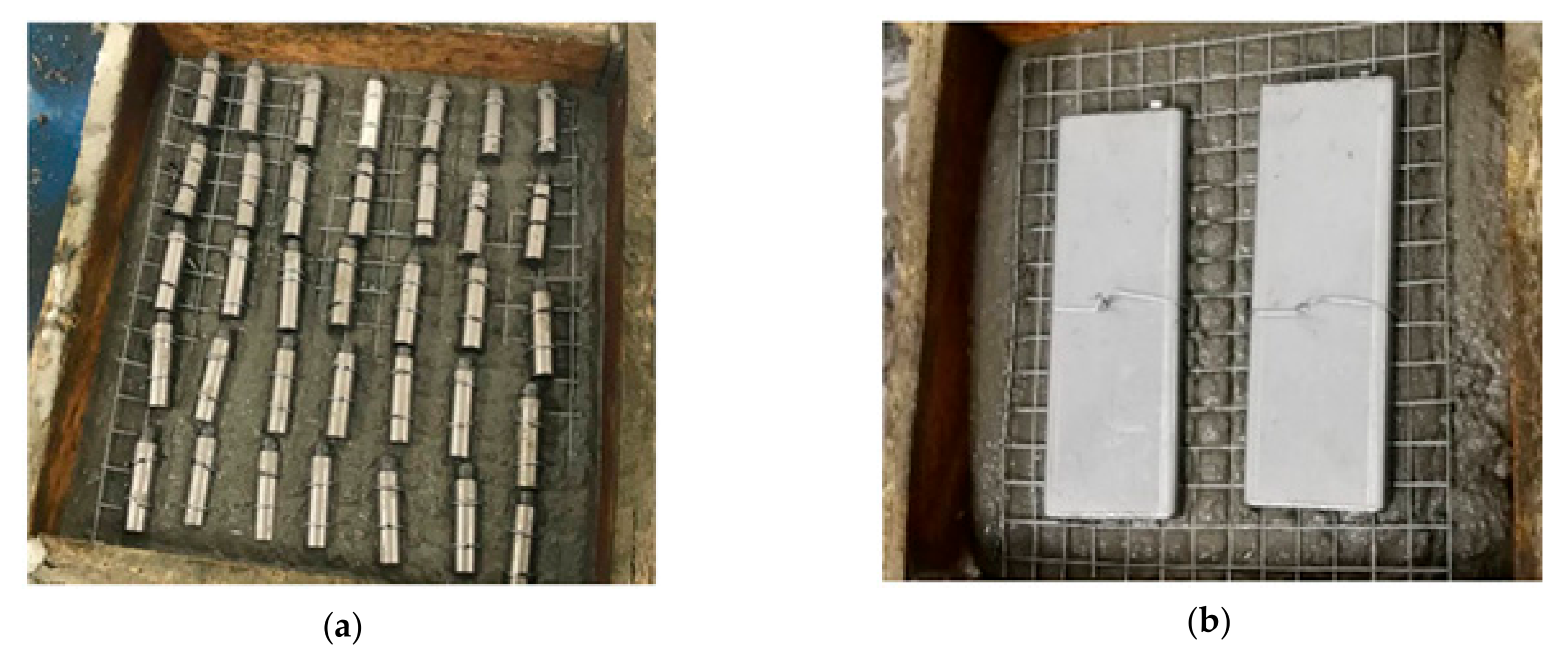
2.1. Sample Preparation

The PCM chosen in this study was organic paraffin Rubitherm RT31 manufactured by Rubitherm GmbH. It was chosen due to its desirable properties such as it not super-cooling during the phase change process, being non-corrosive, and being chemically inert. Its phase change temperature range is within the human comfort temperature range, and it possesses high latent heat capacity. The thermo-physical properties of RT31 are summarized in Table 1.
The two forms of macro-capsule used in this study were: Steel capsule and steel panel. Figure 1 shows the steel capsules and steel panels being placed in the mortar panels. The steel capsules were prepared by milling steel bars using a computer numerical control (CNC) machine with an outer diameter of 10 mm and a wall thickness of 1 mm. The length of the steel capsule was 30 mm, and a steel cap was used to seal the opening. The total amount of paraffin and capsule were 3.0% and 2.9% by volume of the mortar panel, respectively. The steel panel was fabricated by folding and welding steel plates to form a single cavity rectangular container with dimensions of 135 mm × 50 mm × 9 mm. The wall thickness was 2 mm. The total amount of paraffin and the steel panel were 2.6% and 1.5% by volume of the mortar panel, respectively. The mortar samples incorporated with steel panels were compared to the samples with steel capsules to determine effects of different forms of macro capsules on the thermal behavior of mortar panels.
The first step was filling the macro capsules with RT31 paraffin in liquid form. After filling, epoxy adhesive was applied to seal the opening of capsules. Then, the macro capsules were tied to a layer of wire mesh before being inserted into the mortar mix to ensure uniform distribution in the middle of the mortar panels. The mortar mix used in this study adopted a cement to sand ratio of 1:4, while the water cement ratio was 0.5. The cement used was ordinary Portland cement (OPC) type I with a specific gravity of 3.14 g/cm3. The dimensions of mortar panels were 200 mm × 200 mm × 50 mm. The mortar mix was first filled up to the mid-height of timber molds and then compacted properly. Macro capsules (attached to the wire meshes) were placed on top of the compacted mortar mix, as shown in Figure 1. After that, mortar was placed and compacted to achieve a depth of 50 mm for the mortar panels. The mortar panels were cured in water for 28 days before testing. The total volume of the PCM was approximately 3% of the panel volume. Two mortar panels without the PCM were used as control samples. Two panel replicates were prepared for each type of macro capsules, resulting in a total of 6 panels tested.

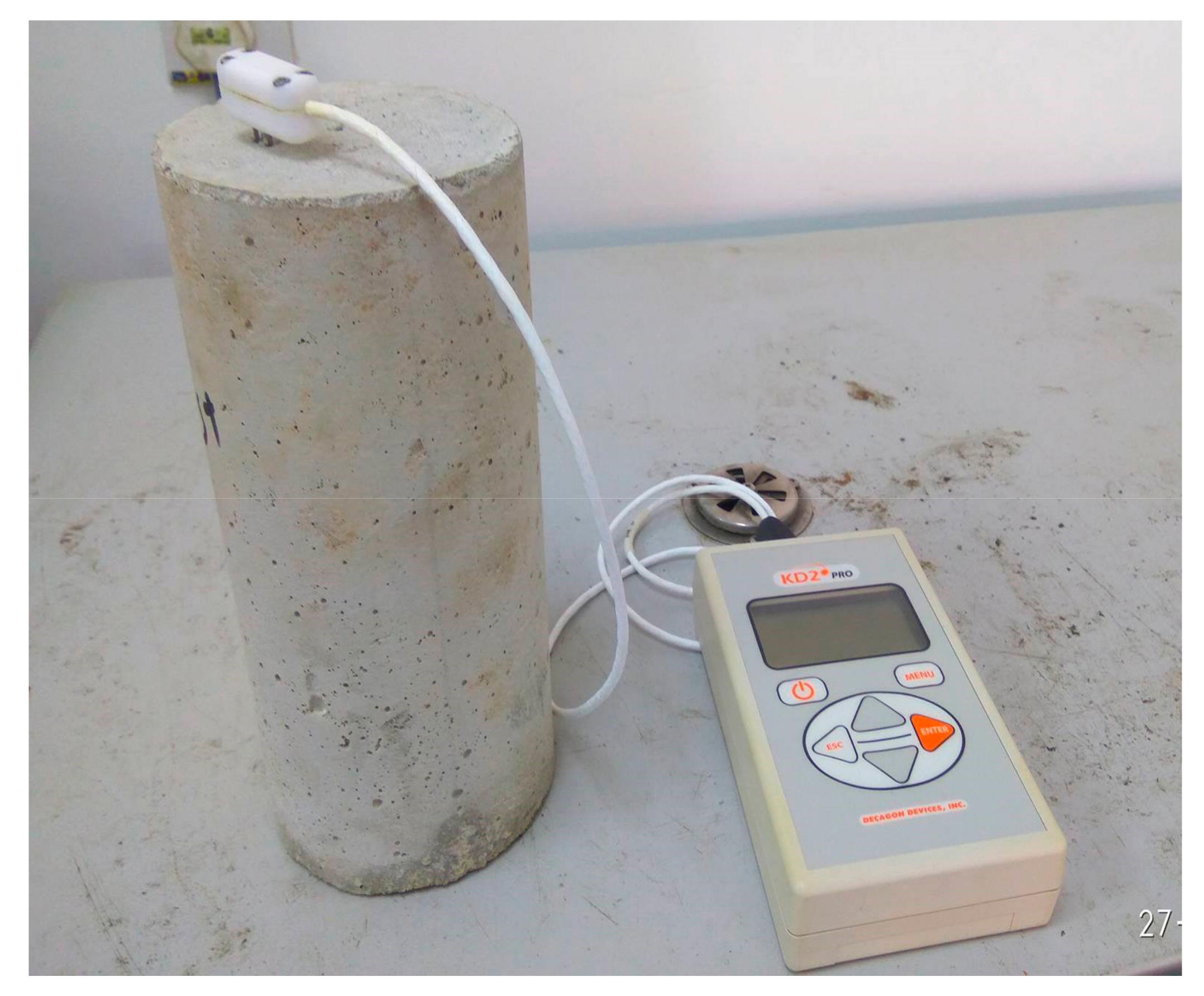
2.2. Thermal Properties of Mortar

KD2Pro thermal properties analyzer (ICT International, Armidale, Australia) is a portable device designed to measure thermal properties, such as thermal conductivity, thermal resistivity, thermal diffusivity, and specific heat. In this study, the thermal conductivity and specific heat of the mortar mix were measured by using the SH-1 probe (which is capable of measuring volumetric hear capacity, thermal diffusivity, thermal conductivity, and thermal resistivity). Three mortar cylinders with a diameter of 100 mm and a height of 200 mm were prepared using the described mix proportion. The measurement was taken by inserting the probe into the mortar cylinder, as illustrated in Figure 2. After each measurement, the device was allowed to equilibrate with the ambient temperature for 15 minutes. The thermal conductivities of the samples were 1.02 W/(m·K), 1.12 W/(m·K) and 1.17 W/(m·K). The specific heats of the samples were 1240.5 J/(kg·K), 1258.6 J/(kg·K) and 1250.2 J/(kg·K). The average thermal conductivity of the mortar mix was 1.1 W/(m·K), while the average specific heat was 1250 J/(kg·K).

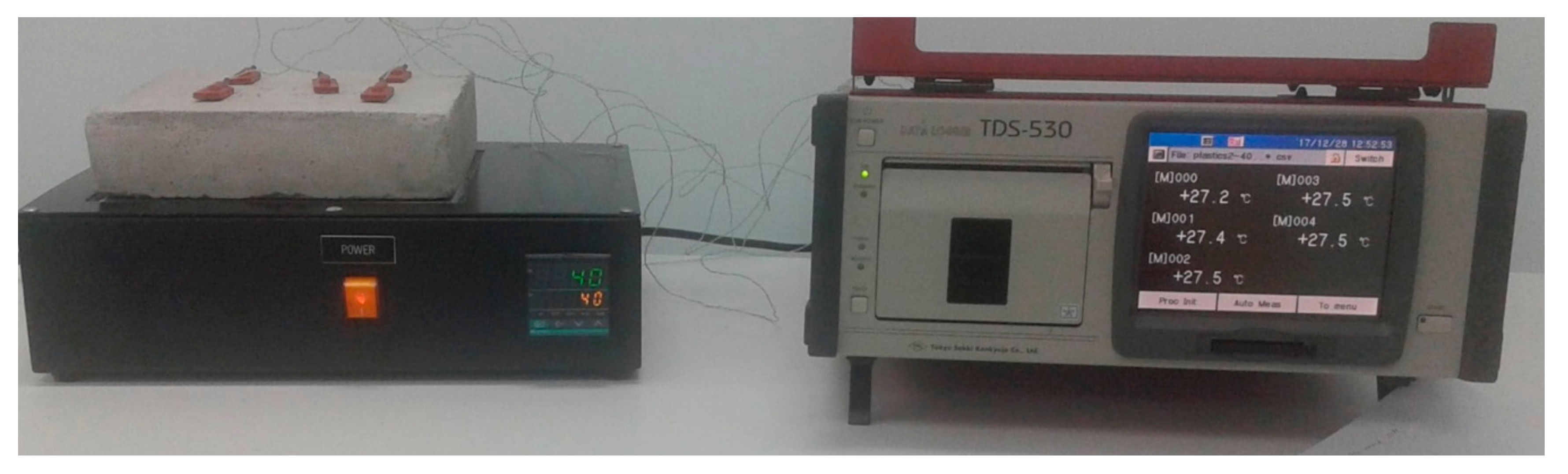
2.3. Thermal Testing of the Composite Mortar Panels

To study the thermal behavior of mortar panels with different forms of macro encapsulated PCMs, an instrumented hot place device was setup using a hotplate, five thermocouples, and a data logger. The mortar panels were placed on top of the hot plate set at 40 °C, and the temperature at the top surface was monitored by thermocouples connected to a data logger, as shown in Figure 3. The setup resulted in a one-dimensional heat transfer from the bottom surface to the top surface of the mortar panels by conduction. The tests were conducted in a room with the temperature controlled at 27 ± 0.5 °C during the testing. Once the panels achieved the steady state, testing was terminated.

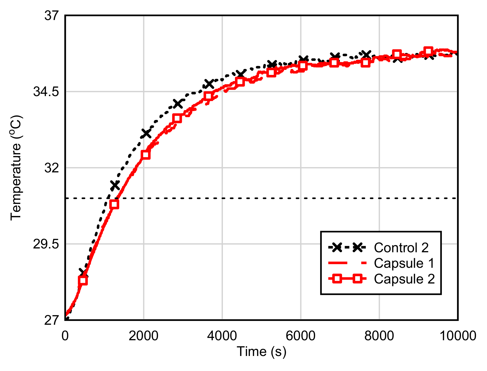
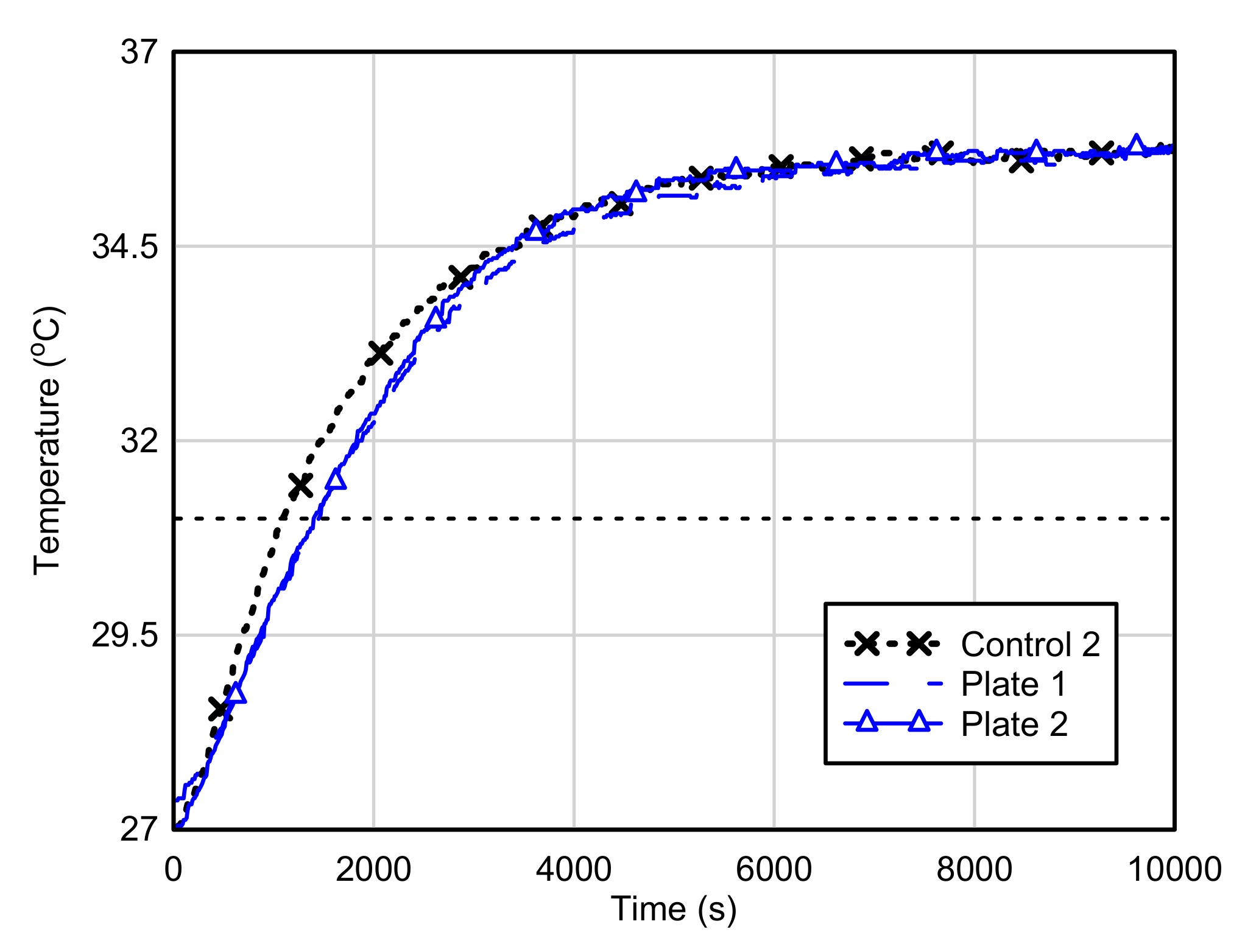
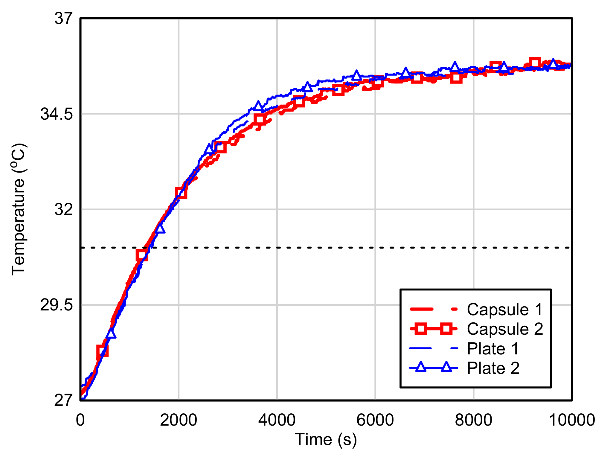
3. Experimental Results

The average experimental top surface temperature of Control Panel 2 and panels with paraffin encapsulated in steel capsules are illustrated in Figure 4. The thickness of Control Panel 1 was only 45 mm, 5 mm less than other panels. This made the temperature increase of Control Panel 1 noticeably higher than that of Control Panel 2—as expected. Therefore, the results of Panel 1 were discarded from further analyses. Control Panel 2 reached steady state after around 7000 s, with a final temperature of 35.7 °C. In comparison, the panels with paraffin in steel capsules showed lower temperatures compared to Control Panel 2 during the transient state, starting from 500 to 6000 s. This is in accordance with published literature [19]. The maximum temperature difference was about 0.7 °C for both samples when compared to Control Panel 2 at around 2000 s, as summarized in Table 2. The lower temperature was attributed to the heat absorbed by the paraffin during phase transition. The panels with macro-encapsulated paraffin showed a time lag of reaching 33 °C at around 400 to 500 s. The panels with paraffin in steel capsules reached the final temperature later than Control Panel 2, at approximately 8000 s. The results suggest that the addition of steel capsules containing the paraffin can retard the temperature increase of concrete because of the heat absorbed by the paraffin during the solid-to-liquid phase change.
The samples with paraffin in steel panels demonstrated a lower temperature from 500 to 4000 s compared to Control Panel 2, as illustrated in Figure 5. A maximum temperature difference of about 0.9 °C was observed at about 1400 s. After 4000 s, the samples with paraffin in steel panels demonstrated a similar thermal response with Control Panel 2. Figure 6 shows the comparison of thermal response for the samples with both forms of macro capsules used in this study. It could be observed that the overall response was similar for both forms of macro capsules. Minor differences could be observed, as the samples with steel panels demonstrated a lower temperature before 2000 s and then a higher temperature between 2000 to 6000 s compared to the samples with paraffin in steel capsules. This may be attributed to the higher amount of steel in the mortar panel containing steel panel, since steel has a higher heat transfer capacity than mortar. The experimental results revealed that paraffin encapsulated in both forms of macro capsule demonstrated similar thermal responses.

4. Finite Element (FE) Analyses

4.1. Description of FE Models

Heat transfer problems involving conduction, convection and radiation can be analyzed using the commercial finite element software package Abaqus. An uncoupled heat transfer analysis was used in this study using Abaqus 2016 since the heat conduction or internal energy in the samples was independent of mechanical stresses, strains, and displacements. The assumptions made for the numerical models were as follows:
  • The thermo-physical properties such as density, heat capacity, and thermal conductivity of the materials were constant and independent of temperature changes.
  • The mortar was assumed to be homogenous and isotropic.
  • The free convection of air was considered on the top surface of mortar panels, and the convection coefficient was constant.
  • The interface resistance was negligible for contact between different components.
The thermo-physical properties of materials used in the simulations are summarized in Table 3. The thermal properties of the mortar were measured using the KD2Pro device, while the standard specifications of RT31 paraffin (Table 1) were adopted in the analysis. The typical values of density and thermal properties were used for steel. The effective heat capacity method was used to model the latent heat effects [34]. This is the most common method for solving thermal problems involving phase changes [33]. In this method, the latent heat of a PCM is modelled as a large effective heat capacity activated within the phase transition temperature. Below the melting temperature of the PCM, the energy is stored by specify heat. Once the PCM reaches the melting temperature, the large effective heat capacity (approximation of latent heat) will control the temperature increase. The temperature will increase again once the large effective heat capacity has been fully utilized. The phase change temperature range was defined by the solidus and liquidus temperatures, and they were set to ± 2 °C from the melting temperature of RT31 in this study. The melting temperature of RT31 was taken as 31° C (Table 1). Thus, the solidus and liquidus temperatures were set at 29 and 33 °C, respectively.
Each component of the mortar panels was modelled in a 3D scheme. To simplify the modelling, the wire mesh was ignored, as its effects on thermal response of mortar panels were insignificant. The tie constraint was defined at the contact surfaces such as mortar–steel and steel–paraffin interfaces. The bottom surface of the mortar panels was assigned with a constant temperature of 40 °C during the analysis. The surface convection was defined for the top surface of mortar panels, as they were exposed to air in the experimental set up. From the finite element (FE) model calibration of the control sample, a film coefficient of 9 W/(m2·K) demonstrated good agreement with the experimental results. Therefore, it was adopted for all the FE models. The components of mortar panels were discretized using first order four-noded linear heat transfer tetrahedron elements. To enhance the accuracy of the numerical models, the paraffin and steel capsules were discretized using a finer mesh. From the convergence study, the optimum mesh size for paraffin and steel capsules was 2 mm, while the mesh size applied on mortar panel was 10 mm.

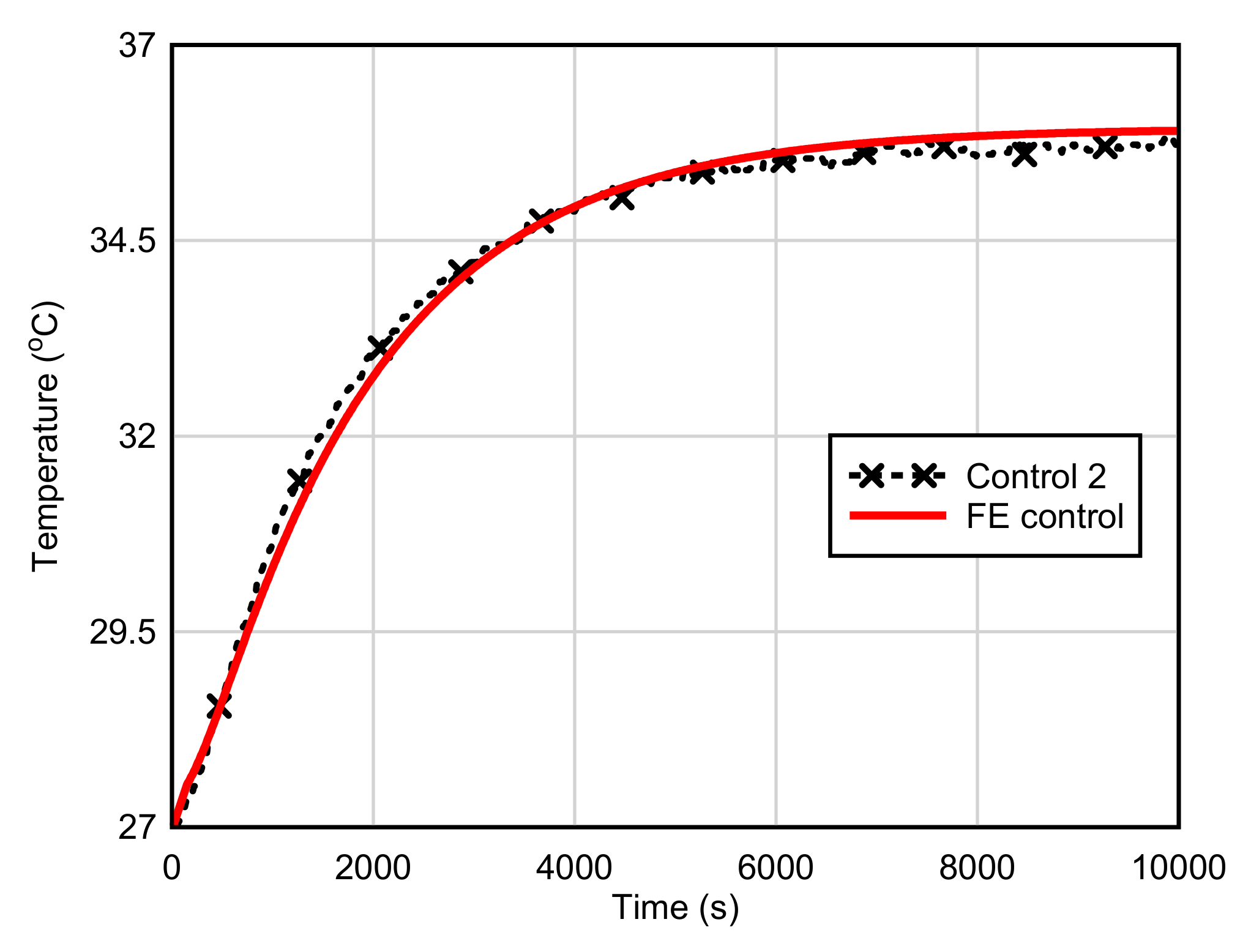
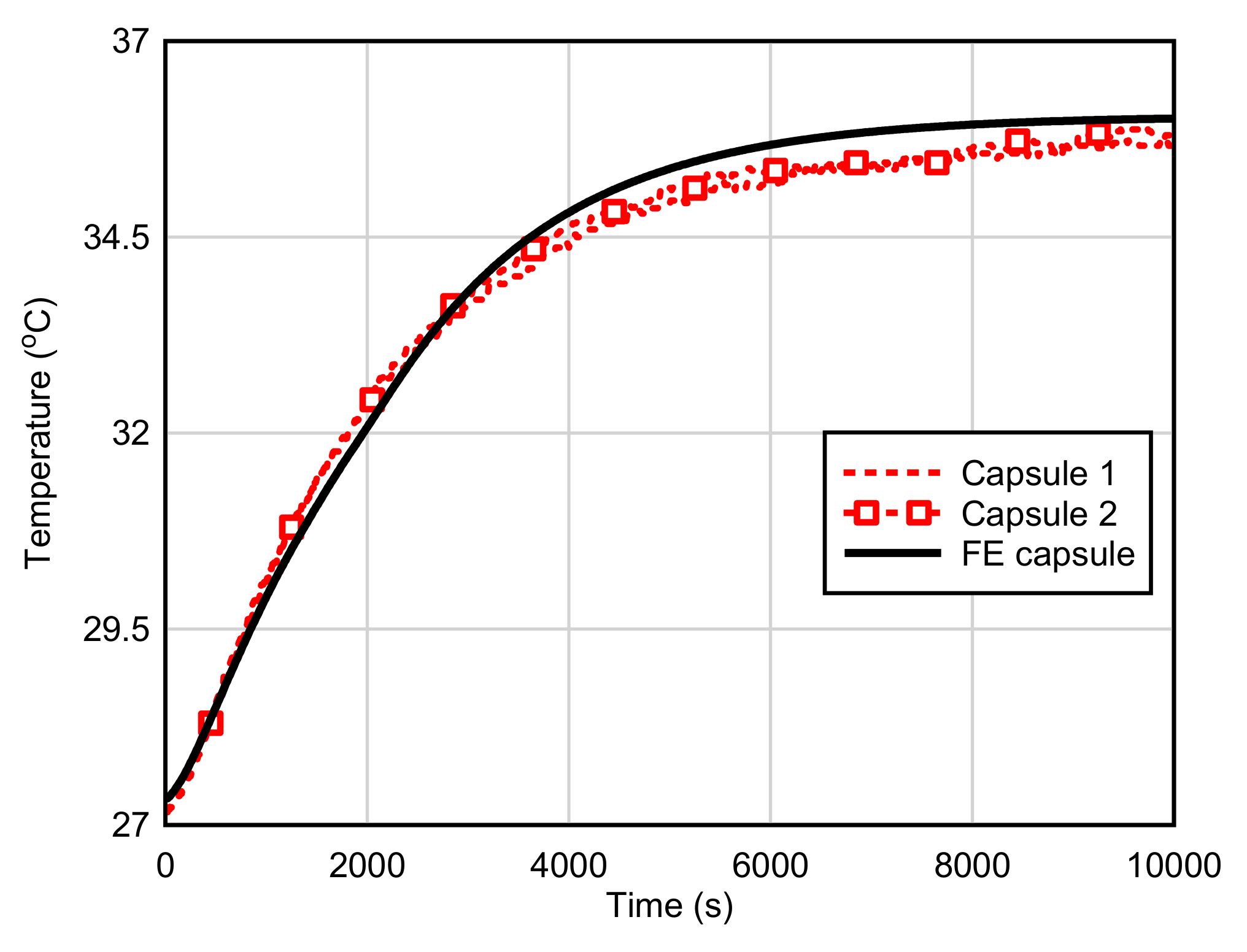
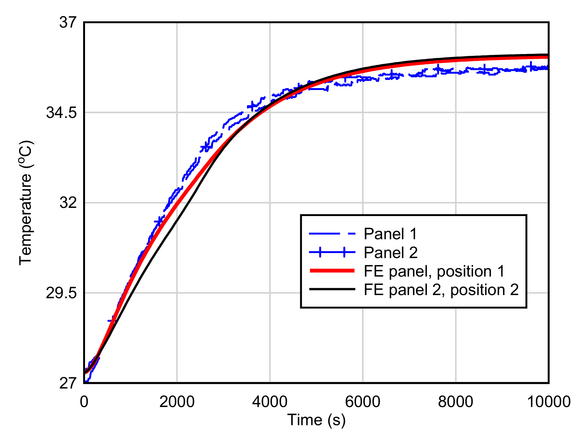
4.2. Model Validation

The control mortar panel (i.e., without PCM macro-capsules) was used to validate the FE model. The predicted temperature time history of the control panel is illustrated in Figure 7. It showed an excellent match with the experimental results of Control Panel 2. The predicted final temperature was 35.9 °C, which was 0.2 °C higher than the experimental results. This showed that the FE model was capable of predicting the thermal response of the mortar panel using the input parameters defined in this study.
Figure 8 shows the comparison between the FE predicted temperature time history with the experimental results of the samples with steel capsules. The FE results matched well with the experimental results up to 3000 s. The FE model predicted a higher final temperature of 36 °C, compared to 35.6 °C from the experimental results. Figure 9 displays the temperature contour plots across the thickness of the FE model. The unit used in the FE model for temperature was Kelvin (K). Figure 9a shows the temperature distribution when RT31 paraffin had reached the melting temperature of 29 °C (302 K), while the paraffin had fully melted in Figure 9b. It can be observed that the temperature of paraffin was lower than the surrounding mortar during the melting process due to its high latent heat capacity. The temperature at the center of the paraffin was lower due to its low thermal conductivity (0.2 W/(m·K)). Once the phase transition completed, the paraffin showed a similar temperature with the surrounding mortar. It could be observed that the mortar immediately behind the steel capsules showed a higher temperature, as steel capsules formed the thermal bridge in the mortar after the phase transition of paraffin. As the distance increased, the thermal bridge effect dismissed, and the top surface showed a uniform temperature distribution.
The FE predicted the temperature response of the sample with paraffin in steel panels, and this response is compared to experimental results in Figure 10. The surface temperature at the top surface may have varied at different locations due to the effect of steel plate. Therefore, the temperature at the top surface was tested at two positions. As seen in Figure 10, both “FE Plate Position 1” and “FE Plate Position 2” present the temperature at the top surface of the mortar panel. Position 1 was at the center of the two steel plates, and Position 2 was right above the steel plate, as shown in Figure 11. During the transient state, the average experimental temperature corresponded well with the temperature predicted at the center. The predicted temperature behind the steel panels was lower than the experimental results, with a maximum difference of 0.8 °C. After the phase transition of paraffin, the FE model predicted a uniform temperature distribution at the top surface. From Figure 11, it can be observed that the temperature of the mortar adjacent to the side walls of the steel panels was higher during the phase transition of paraffin. The rear wall of steel panels showed a lower temperature compared to the side walls, as the heat transferred to the rear wall was absorbed by the paraffin. After the phase transition of paraffin, the steel panels acted as a thermal bridge where heat could be transferred through the steel panels faster, causing a higher temperature in the mortar behind the steel panels compared to the mortar in between the steel panels at the same distance from heat source.

4.3. Parametric Studies

The FE modelling of temperature transfer with and without the PCM has been validated above. Therefore, some further explorations can be conducted using validated FE modelling. In aprticular, a parametric study was conducted using the validated FE model with steel capsules to investigate the effects of different forms of macro capsules, the quantity of paraffin, and the position of the macro capsules on the thermal response of mortar panels.

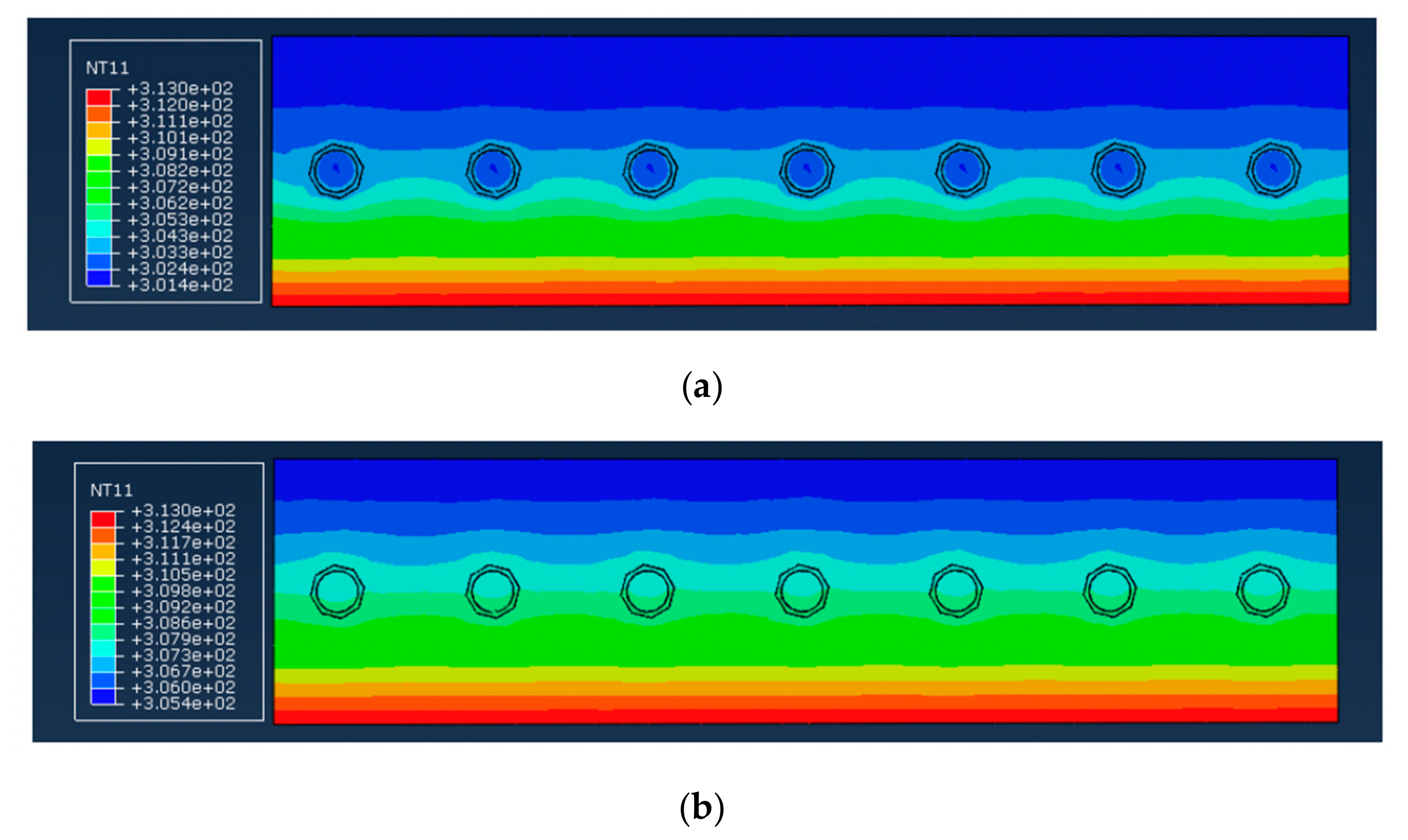
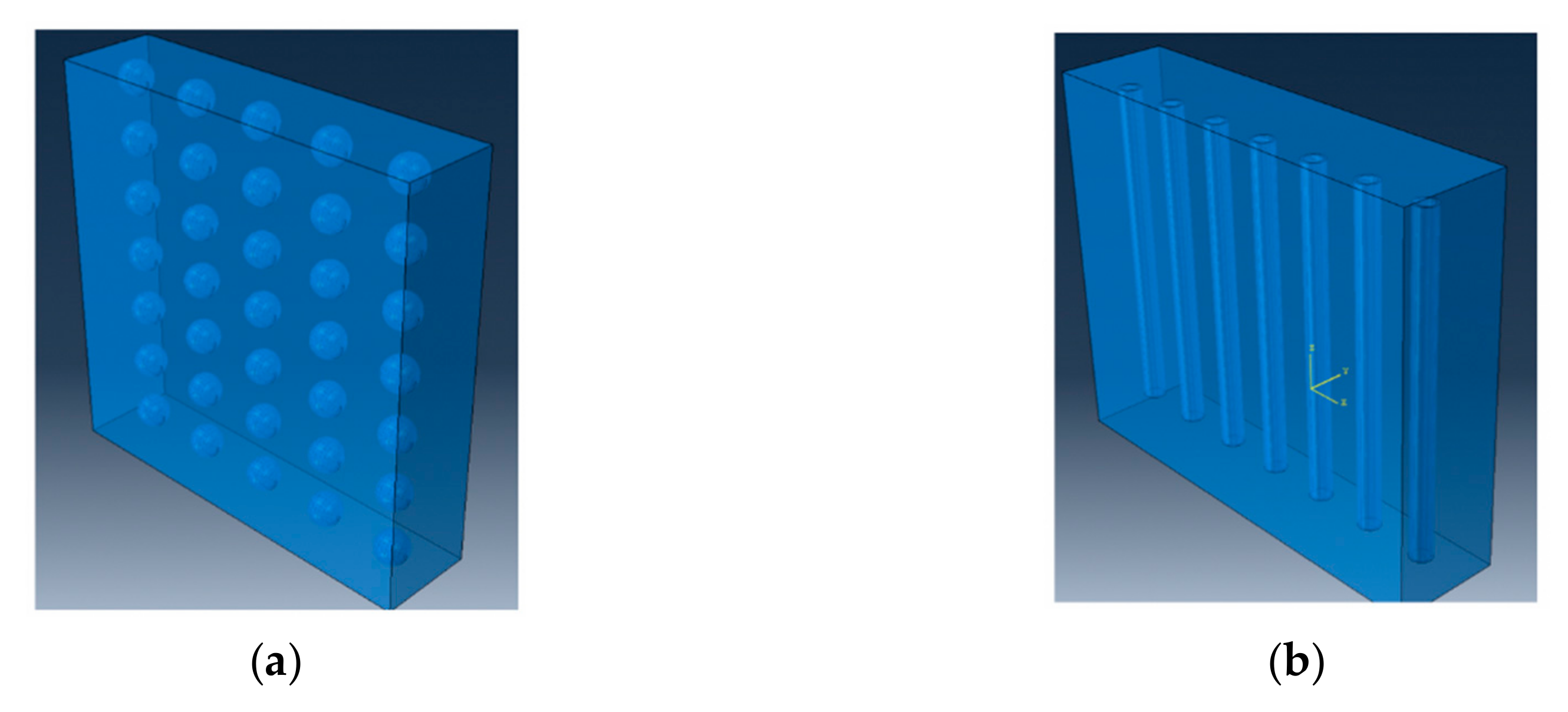
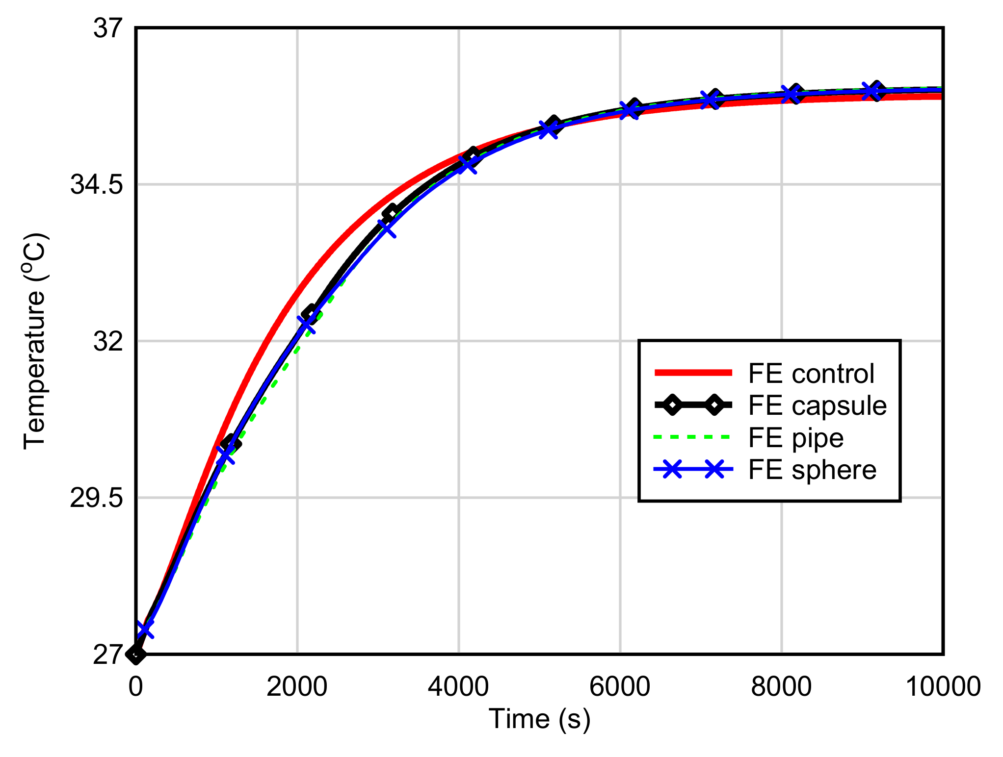
4.3.1. Form of Macro Capsules

The two forms of macro capsule investigated using validated FE modelling techniques were sphere and pipe, as shown in Figure 12. A spherical capsule was chosen, as it has been investigated comprehensively [21] and could be used as a benchmark for the macro capsules proposed in this study. The pipe capsule was proposed, as it would simplify fabrication compared to the steel capsules used in this study and expedite the preparation of mortar panels. The pipe capsule could be fabricated by sealing both ends of the pipe by welding. The arrangement of the spherical macro capsules was similar to the steel capsules used in the test where there were 35 spherical capsules with a wall thickness of 1 mm. For the pipe capsules, the outer diameter and wall thickness was 10 mm and 1 mm, respectively. There were seven pipes in the panel, with a center to center spacing of 29 mm. The volume of paraffin was 3% for all the panels.
Figure 13 shows that the overall response of panels incorporated with different forms of macro capsules was similar. When compared to the FE result of the control panel, the panels with spherical and pipe macro capsules showed a lower temperature during the phase transition of paraffin and a slightly higher temperature at the steady state, as summarized in Table 4. The time lag to reach 33 °C and the final temperature of mortar panels with spherical and pipe macro capsules were identical to the panel with steel capsules. The temperature on the top surface of panel with pipe capsules was 0.1 °C lower from 1000 to 4000 s compared to the panel with steel capsules. The pipe capsules were slightly more effective than the steel capsules, as they could lower the top surface temperature more. The spherical capsules could reduce the top surface temperature by 0.1 °C from 2000 to 4000 s compared to steel capsules. However, the maximum temperature difference during the phase transition of paraffin was the same for both forms of capsules when compared to the control panel, as shown in Table 4. From these results, it could be concluded that the pipe capsules were slightly better than the steel capsules and spherical capsules in term of thermal performance. On the other hand, since 0.1 °C is a very limited difference, the FE simulation results also suggest that the form of the macro capsule considered in this study has very limited effect on the heat transfer of mortar panels.

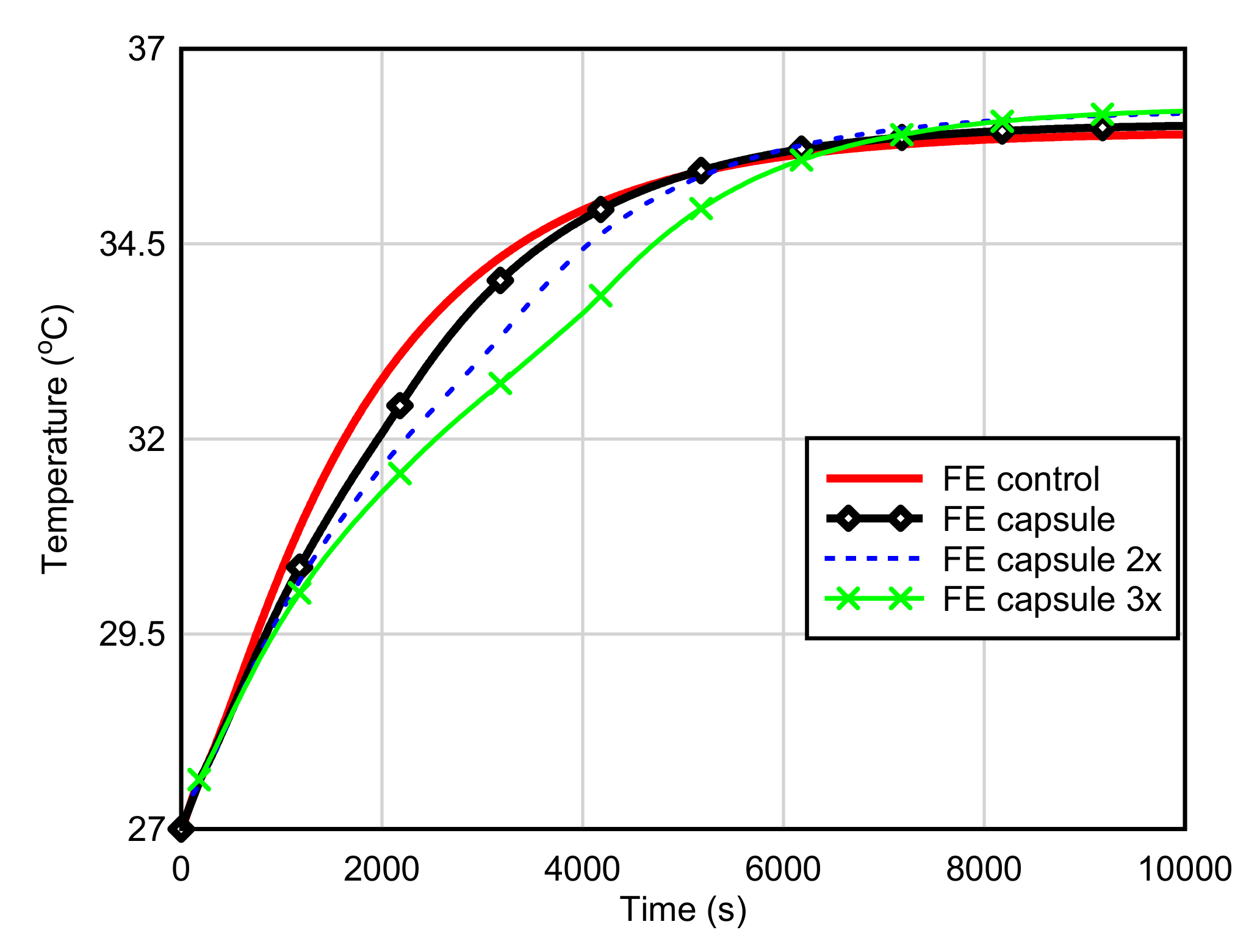
4.3.2. Amount of Paraffin

The amounts of paraffin considered in the model were 3%, 6%, and 9%. The quantity was increased by increasing the inner diameter of steel capsule, while other input parameters were kept constant. The temperature time histories of panels incorporated with various quantities of paraffin are shown in Figure 14. As the quantity of paraffin increased, the temperature on the top surface reduced during the phase transition of paraffin, and the lag time increased significantly, as summarized in Table 4. Thus, the amount of paraffin is an influential factor affecting the heat transfer of the mortar panel. Figure 15 shows the temperature contour plot of a panel with 9% of paraffin at 4000 s when the temperature difference with the control panel was at the maximum during the transient state. It could be observed that, as the diameter increased, less heat could be transferred to the core due to the low thermal conductivity of paraffin. The final temperature increased when the paraffin quantity increased due to the increased inner diameter of the steel capsules. The larger diameter of the steel capsules caused a larger amount of steel in the mortar panel and acted as the thermal bridge, thus resulting in a higher final temperature on the top surface. Therefore, the capsule material should be carefully selected when a high amount of paraffin is incorporated into the mortar panel. A material with a lower conductivity may be preferred compared to steel.

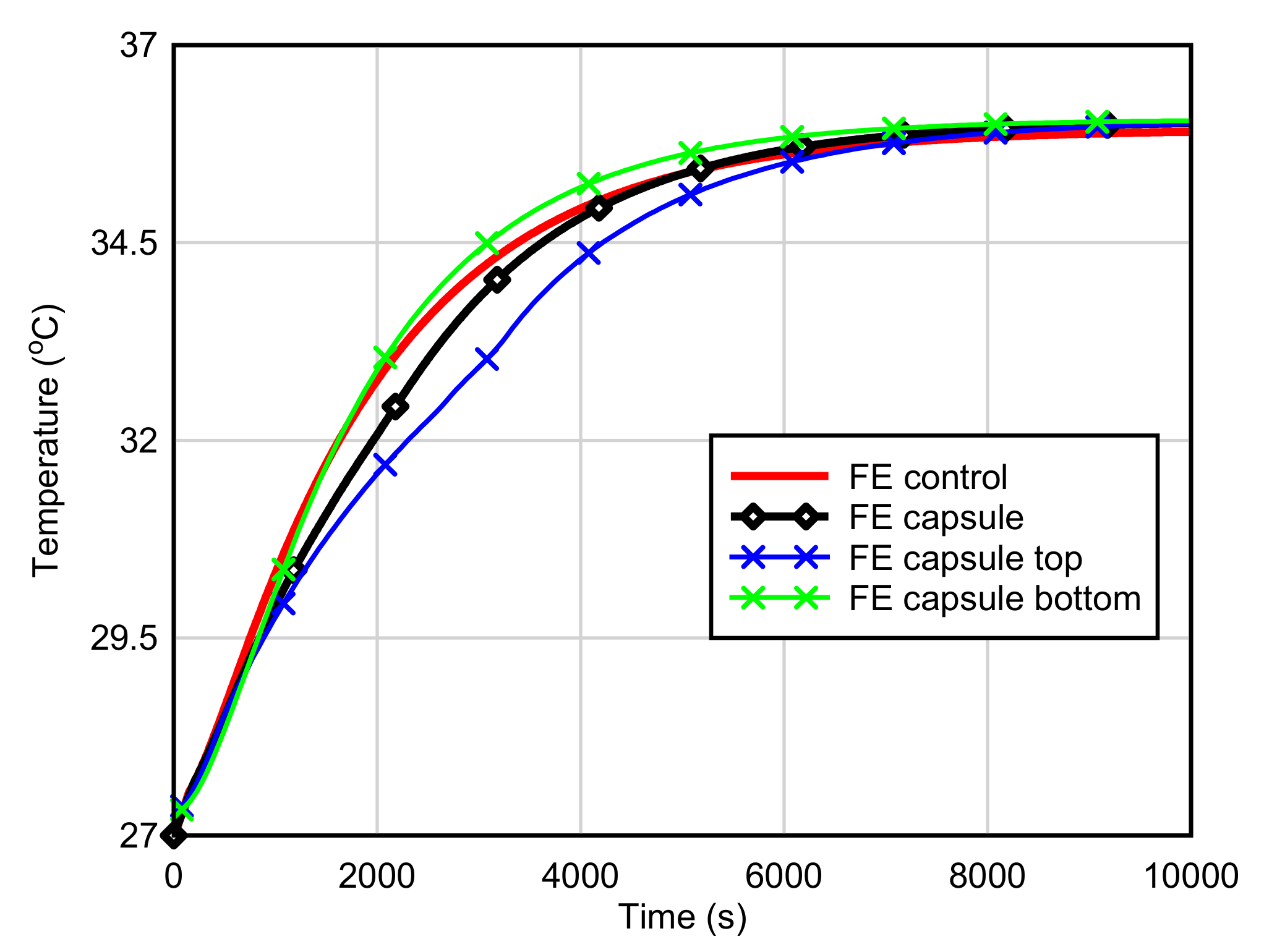
4.3.3. Position of Macro Capsules

The effects of steel capsules position were studied by placing steel capsules nearer to the top and bottom surfaces. A constant temperature of 40 °C was applied on the bottom surface of the mortar panels. The steel capsules were shifted ±15 mm in the thickness direction, and the cover was 10 mm. Figure 16 shows the temperature time histories of the panels with steel capsules placed at various positions. It shows that, by placing the steel capsules nearer to the bottom surface (where the heat was applied), the paraffin had little effect on the top surface temperature during phase transition, as summarized in Table 4. The temperature dropped only by 0.2 °C, and the lag time was 1500 s, compared to the control panel. After the phase transition of paraffin, the FE model predicted a higher temperature on the top surface during the transient state. The macro encapsulated paraffin demonstrated a more favorable response when it was placed further away from the heat source—in this case, near to the top surface of the panel. The temperature reduction increased to 1.2 °C, and the time lag increased to 890 s. This observation was in line with the experimental results on insulated gypsum walls [23]. According to this, paraffin position is also an influential factor affecting the heat transfer of mortar panels.

5. Conclusions

This paper presented numerical investigations of the thermal response of mortar panels incorporating paraffin encapsulated in different forms of macro capsules. The FE models were first validated against the experimental results of mortar panels incorporated with the two forms of macro capsules fabricated in this study. Then, a parametric study was conducted to evaluate the effects of different forms of macro capsules, the quantity of paraffin, and the position of the macro capsules on the thermal response of cement mortar panels. Based on the numerical simulation results, the following conclusions can be drawn:
1.
The capsule forms considered in this study, such as tube and sphere, showed little difference in term of the thermal response of the mortar panels when the amount of paraffin was the same. The plate-shaped capsule may cause a more pronounced non-uniform temperature distribution in the panels compared to the other shapes. When the size of the capsule increases, thermal bridge effects become more pronounced after the phase transition of paraffin.
2.
Both the amount of paraffin and the capsule position are influential factors affecting the heat transfer pattern of the mortar panel. A higher paraffin amount significantly increases the time lag and reduces the mortar temperature during the phase transition of paraffin. It should be noted that when a large amount of paraffin is encapsulated in macro capsules, the efficiency of paraffin in absorbing heat may be reduced due to its low thermal conductivity.
3.
Placing the encapsulated paraffin at a larger distance away from the heating source can provide a longer time lag on the other face.

Author Contributions

S.Y.K. and X.Y. defined the scopes of the study. All authors performed the literature study. All authors wrote the manuscript and commented on the final draft.

Funding

This work was undertaken with funding from Ministry of Higher Education of Malaysia under FRGS grant scheme (Program code. FRGS/1/2015/TK10/MUSM/03/1).

Acknowledgments

The authors would like to express gratitude to Low Yee Han for his kind assistance in sample preparation.

Conflicts of Interest

The authors declare no conflict of interest

References

  1. Fernandes, F.; Manari, S.; Aguayo, M.; Santos, K.; Oey, T.; Wei, Z.; Falzone, G.; Neithalath, N.; Sant, G. On the feasibility of using phase change materials (PCMs) to mitigate thermal cracking in cementitious materials. Cem. Concr. Compos. 2014, 51, 14–26. [Google Scholar] [CrossRef]
  2. Farnam, Y.; Krafcik, M.; Liston, L.; Washington, T.; Erk, K.; Tao, B.; Weiss, J. Evaluating the use of phase change materials in concrete pavement to melt ice and snow. J. Mater. Civ. Eng. 2015, 28, 04015161. [Google Scholar] [CrossRef]
  3. Šavija, B. Smart crack control in concrete through use of phase change materials (PCMs): A review. Materials 2018, 11, 654. [Google Scholar] [CrossRef]
  4. Kim, S.; Chang, S.J.; Chung, O.; Jeong, S.-G.; Kim, S. Thermal characteristics of mortar containing hexadecane/xGnP SSPCM and energy storage behaviors of envelopes integrated with enhanced heat storage composites for energy efficient buildings. Energy Build. 2014, 70, 472–479. [Google Scholar] [CrossRef]
  5. Cui, H.; Liao, W.; Mi, X.; Lo, T.Y.; Chen, D. Study on functional and mechanical properties of cement mortar with graphite-modified microencapsulated phase-change materials. Energy Build. 2015, 105, 273–284. [Google Scholar] [CrossRef]
  6. Lecompte, T.; Le Bideau, P.; Glouannec, P.; Nortershauser, D.; Le Masson, S. Mechanical and thermo-physical behaviour of concretes and mortars containing phase change material. Energy Build. 2015, 94, 52–60. [Google Scholar] [CrossRef]
  7. Jayalath, A.; San Nicolas, R.; Sofi, M.; Shanks, R.; Ngo, T.; Aye, L.; Mendis, P. Properties of cementitious mortar and concrete containing micro-encapsulated phase change materials. Constr. Build. Mater. 2016, 120, 408–417. [Google Scholar] [CrossRef]
  8. Ricklefs, A.; Thiele, A.M.; Falzone, G.; Sant, G.; Pilon, L. Thermal conductivity of cementitious composites containing microencapsulated phase change materials. Int. J. Heat Mass Transf. 2017, 104, 71–82. [Google Scholar] [CrossRef] [Green Version]
  9. Aguayo, M.; Das, S.; Maroli, A.; Kabay, N.; Mertens, J.C.; Rajan, S.D.; Sant, G.; Chawla, N.; Neithalath, N. The influence of microencapsulated phase change material (PCM) characteristics on the microstructure and strength of cementitious composites: Experiments and finite element simulations. Cem. Concr. Compos. 2016, 73, 29–41. [Google Scholar] [CrossRef] [Green Version]
  10. Haurie, L.; Serrano, S.; Bosch, M.; Fernandez, A.I.; Cabeza, L.F. Single layer mortars with microencapsulated PCM: Study of physical and thermal properties, and fire behaviour. Energy Build. 2016, 111, 393–400. [Google Scholar] [CrossRef] [Green Version]
  11. Šavija, B.; Zhang, H.; Schlangen, E. Influence of microencapsulated phase change material (PCM) addition on (micro) mechanical properties of cement paste. Materials 2017, 10, 863. [Google Scholar] [CrossRef] [PubMed]
  12. Šavija, B.; Luković, M.; Kotteman, G.M.; Figuieredo, S.C.; de Mendoça Filho, F.F.; Schlangen, E. Development of ductile cementitious composites incorporating microencapsulated phase change materials. Int. J. Adv. Eng. Sci. Appl. Math. 2017, 9, 169–180. [Google Scholar] [CrossRef] [Green Version]
  13. Drissi, S.; Ling, T.-C.; Mo, K.H.; Eddhahak, A. A review of microencapsulated and composite phase change materials: Alteration of strength and thermal properties of cement-based materials. Renew. Sustain. Energy Rev. 2019, 110, 467–484. [Google Scholar] [CrossRef]
  14. Vicente, R.; Silva, T. Brick masonry walls with PCM macrocapsules: An experimental approach. Appl. Therm. Eng. 2014, 67, 24–34. [Google Scholar] [CrossRef]
  15. He, Y.; Zhang, X.; Zhang, Y.; Song, Q.; Liao, X. Utilization of lauric acid-myristic acid/expanded graphite phase change materials to improve thermal properties of cement mortar. Energy Build. 2016, 133, 547–558. [Google Scholar] [CrossRef]
  16. Alam, T.E.; Dhau, J.S.; Goswami, D.Y.; Stefanakos, E. Macroencapsulation and characterization of phase change materials for latent heat thermal energy storage systems. Appl. Energy 2015, 154, 92–101. [Google Scholar] [CrossRef] [Green Version]
  17. Navarro, L.; de Gracia, A.; Castell, A.; Álvarez, S.; Cabeza, L.F. PCM incorporation in a concrete core slab as a thermal storage and supply system: Proof of concept. Energy Build. 2015, 103, 70–82. [Google Scholar] [CrossRef] [Green Version]
  18. Navarro, L.; de Gracia, A.; Castell, A.; Cabeza, L.F. Experimental evaluation of a concrete core slab with phase change materials for cooling purposes. Energy Build. 2016, 116, 411–419. [Google Scholar] [CrossRef] [Green Version]
  19. Kong, X.; Lu, S.; Li, Y.; Huang, J.; Liu, S. Numerical study on the thermal performance of building wall and roof incorporating phase change material panel for passive cooling application. Energy Build. 2014, 81, 404–415. [Google Scholar] [CrossRef]
  20. Shi, X.; Memon, S.A.; Tang, W.; Cui, H.; Xing, F. Experimental assessment of position of macro encapsulated phase change material in concrete walls on indoor temperatures and humidity levels. Energy Build. 2014, 71, 80–87. [Google Scholar] [CrossRef]
  21. Cui, H.; Tang, W.; Qin, Q.; Xing, F.; Liao, W.; Wen, H. Development of structural-functional integrated energy storage concrete with innovative macro-encapsulated PCM by hollow steel ball. Appl. Energy 2017, 185, 107–118. [Google Scholar] [CrossRef]
  22. D’Alessandro, A.; Pisello, A.L.; Fabiani, C.; Ubertini, F.; Cabeza, L.F.; Cotana, F. Multifunctional smart concretes with novel phase change materials: Mechanical and thermo-energy investigation. Appl. Energy 2018, 212, 1448–1461. [Google Scholar] [CrossRef] [Green Version]
  23. Jin, X.; Medina, M.A.; Zhang, X. On the importance of the location of PCMs in building walls for enhanced thermal performance. Appl. Energy 2013, 106, 72–78. [Google Scholar] [CrossRef]
  24. Lee, K.O.; Medina, M.A.; Raith, E.; Sun, X. Assessing the integration of a thin phase change material (PCM) layer in a residential building wall for heat transfer reduction and management. Appl. Energy 2015, 137, 699–706. [Google Scholar] [CrossRef]
  25. Lachheb, M.; Karkri, M.; Nasrallah, S.B. Development and thermal characterization of an innovative gypsum-based composite incorporating phase change material as building energy storage system. Energy Build. 2015, 107, 93–102. [Google Scholar] [CrossRef]
  26. Moulahi, C.; Trigui, A.; Karkri, M.; Boudaya, C. Thermal performance of latent heat storage: Phase change material melting in horizontal tube applied to lightweight building envelopes. Compos. Struct. 2016, 149, 69–78. [Google Scholar] [CrossRef]
  27. Erlbeck, L.; Schreiner, P.; Schlachter, K.; Dörnhofer, P.; Fasel, F.; Methner, F.-J.; Rädle, M. Adjustment of thermal behavior by changing the shape of PCM inclusions in concrete blocks. Energy Convers. Manag. 2018, 158, 256–265. [Google Scholar] [CrossRef]
  28. Navarro, L.; de Gracia, A.; Castell, A.; Cabeza, L.F. Experimental study of an active slab with PCM coupled to a solar air collector for heating purposes. Energy Build. 2016, 128, 12–21. [Google Scholar] [CrossRef] [Green Version]
  29. Saikia, P.; Azad, A.S.; Rakshit, D. Thermodynamic analysis of directionally influenced phase change material embedded building walls. Int. J. Therm. Sci. 2018, 126, 105–117. [Google Scholar] [CrossRef]
  30. Wi, S.; Jeong, S.-G.; Chang, S.J.; Lee, J.; Kim, S. Evaluation of energy efficient hybrid hollow plaster panel using phase change material/xGnP composites. Appl. Energy 2017, 205, 1548–1559. [Google Scholar] [CrossRef]
  31. Šavija, B.; Schlangen, E. Use of phase change materials (PCMs) to mitigate early age thermal cracking in concrete: Theoretical considerations. Constr. Build. Mater. 2016, 126, 332–344. [Google Scholar] [CrossRef] [Green Version]
  32. Nayak, S.; Krishnan, N.A.; Das, S. Microstructure-guided numerical simulation to evaluate the influence of phase change materials (PCMs) on the freeze-thaw response of concrete pavements. Constr. Build. Mater. 2019, 201, 246–256. [Google Scholar] [CrossRef] [Green Version]
  33. Caggiano, A.; Mankel, C.; Koenders, E. Reviewing theoretical and numerical models for PCM-embedded cementitious composites. Buildings 2019, 9, 3. [Google Scholar] [CrossRef]
  34. Lamberg, P.; Lehtiniemi, R.; Henell, A.-M. Numerical and experimental investigation of melting and freezing processes in phase change material storage. Int. J. Therm. Sci. 2004, 43, 277–287. [Google Scholar] [CrossRef]
Figure 1. Mortar panels incorporated with different forms of macro-encapsulated PCMs: (a) Steel capsules and (b) steel panels.
Energies 12 02636 g001
Figure 2. Measurement of thermal properties of mortar using the KD2Pro device.
Energies 12 02636 g002
Figure 3. Instrumented hot plate test on mortar panels.
Energies 12 02636 g003
Figure 4. Measured temperatures of the panel with steel capsules compared to the control.
Energies 12 02636 g004
Figure 5. Measured temperatures of the panel with steel panels compared to the control.
Energies 12 02636 g005
Figure 6. Comparison of measured temperatures for panels with different forms of macro-capsules.
Energies 12 02636 g006
Figure 7. Predicted results of control panel compared to the experimental results.
Energies 12 02636 g007
Figure 8. Predicted results of the sample with steel capsules compared to the experimental results.
Energies 12 02636 g008
Figure 9. FE-predicted temperature distribution across the panel with paraffin in steel capsules. (a) Paraffin started to melt at 29 °C (302 K), and (b) paraffin fully melted at 33 °C (306 K).
Energies 12 02636 g009
Figure 10. Predicted results of sample with steel panels compared to the experimental results.
Energies 12 02636 g010
Figure 11. FE-predicted temperature distribution across the panel with paraffin in steel panels at (a) paraffin in melting state and (b) paraffin fully melted.
Energies 12 02636 g011
Figure 12. FE models with different form of macro capsules; (a) spheres and (b) pipes.
Energies 12 02636 g012
Figure 13. FE-predicted temperature time histories for panel using different forms of macro capsules.
Energies 12 02636 g013
Figure 14. FE-predicted temperature time histories for panels with various quantities of paraffin in steel capsules.
Energies 12 02636 g014
Figure 15. FE-predicted temperature distribution across the panel with 9% of paraffin in steel capsules at 4000 s.
Energies 12 02636 g015
Figure 16. FE-predicted temperature time histories for panel with paraffin in steel capsules at various positions.
Energies 12 02636 g016
Table 1. Thermo-physical properties of the phase change material (PCM) Rubitherm RT31.
PropertyValue
Density, kg/m3880
Specific heat, kJ/(kg·K)2.0
Thermal conductivity, W/(m·k)0.2
Latent heat, (kJ/kg)165
Melting temperature, °C (main peak)31
Table 2. Summary of experimental results.
SampleTime Lag to Reach 33 °C (s) Compared to the Control PanelMaximum Temperature Reduction during the Transient State (°C)
Capsule 14200.7
Capsule 25100.7
Plate 14400.8
Plate 24000.9
Table 3. Thermo-physical properties of materials used in finite element (FE) models.
MaterialsDensity
(kg/m3)
Thermal Conductivity
(W/m·K)
Specific Heat
(kJ/kg·K)
Latent Heat
(kJ/kg)
Steel8000550.45-
Mortar19801.11.25-
RT31 paraffin8800.22.00165
Table 4. Summary of the results of parametric studies.
ParameterTime Lag to Reach 33 °C Compared to FE Model of the Control Panel(s)
Temperature Difference at Steady State Compared to Control Panel (°C)Maximum Temperature Difference during the Phase Transition of Paraffin Compared to Control Panel (°C)Influential Factor?
FormCapsules340+0.1−0.7No
Sphere440+0.1−0.7
Pipe440+0.1−0.8
Quantity3%340+0.1−0.7Yes
6%780+0.2−1.2
9%1340+0.2−1.6
PositionCentre340+0.1−0.7Yes
Bottom0+0.1−0.2
Top890+0.1−1.2

