
A Versatile Approach to Polygonal Object Avoidance in Indoor Environments with Hardware Schemes Using an FPGA-Based Multi-Robot
 , ,
, ,
Abstract
:1. Introduction
- Hardware scheme-based algorithms for the identification of obstacle types and their orientation in the indoor environment.
- The behavioral control mechanism approach has been developed for switching between formation to deformation and vice versa to execute obstacle avoidance.
- The decentralization of multi-robots using a hardware scheme-based heuristic algorithm to perform obstacle avoidance with respect to the type of the obstacle and its orientation. Partial reconfiguration (PR) flow integration was used to achieve optimized resource utilization on run-time implementation.
2. Hardware-Based Algorithms
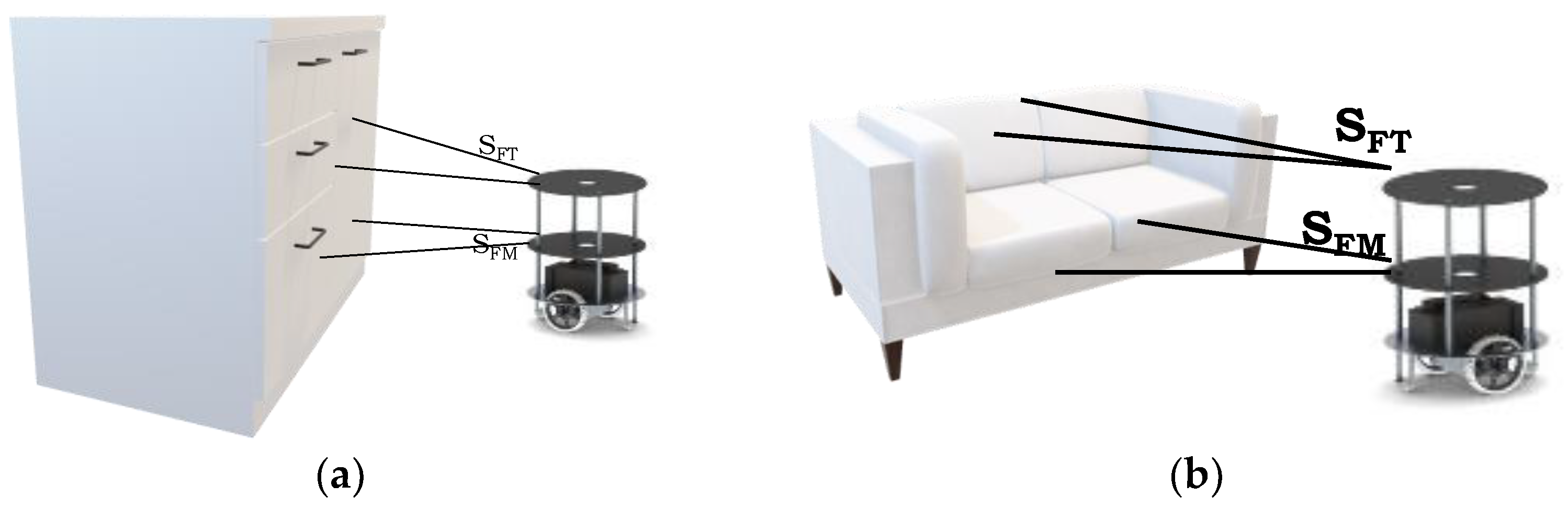
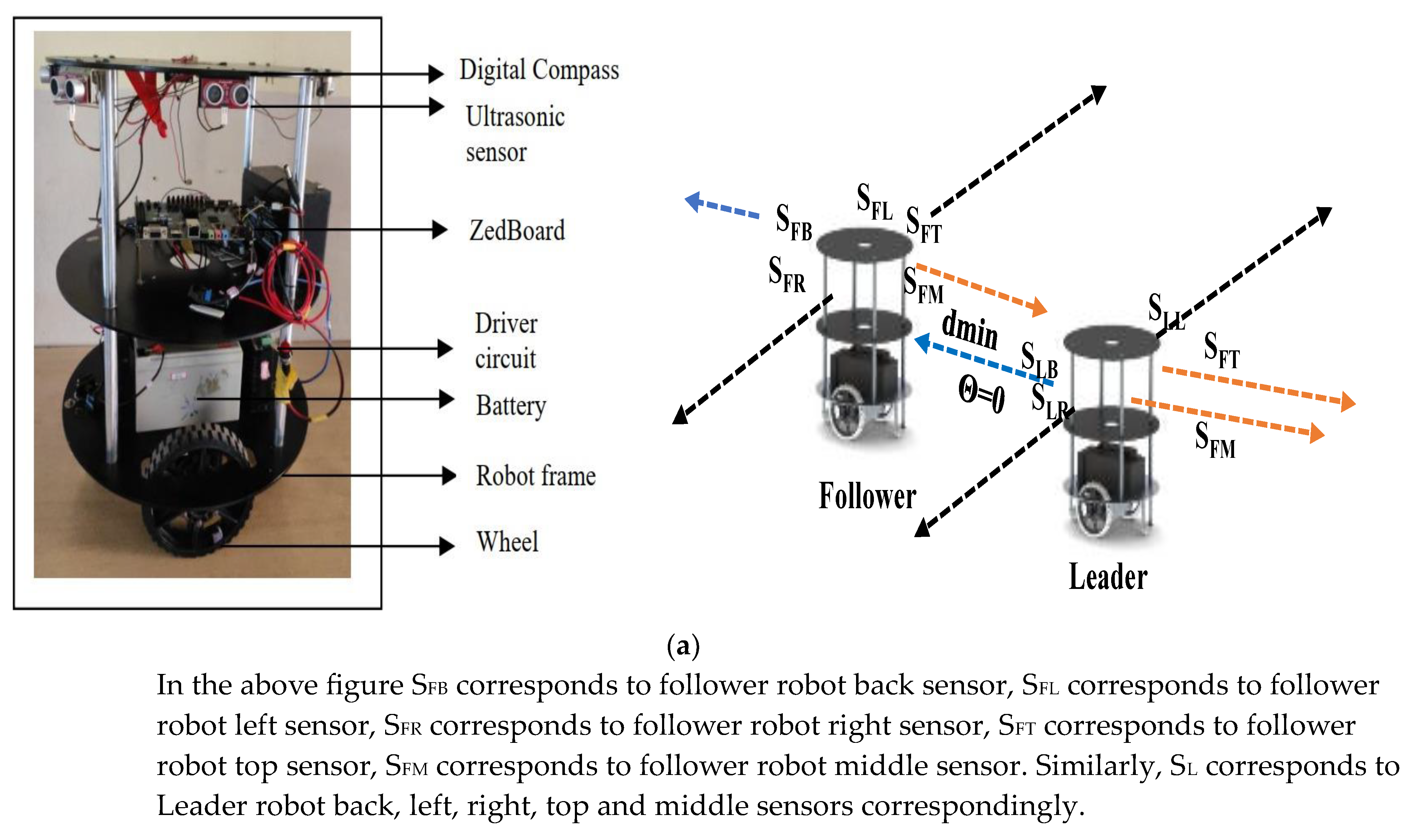
2.1. Hardware-Based Algorithm for Obstacle Identification and Orientation
| Algorithm 1: Pseudo code for identification of obstacle and orientation |
|
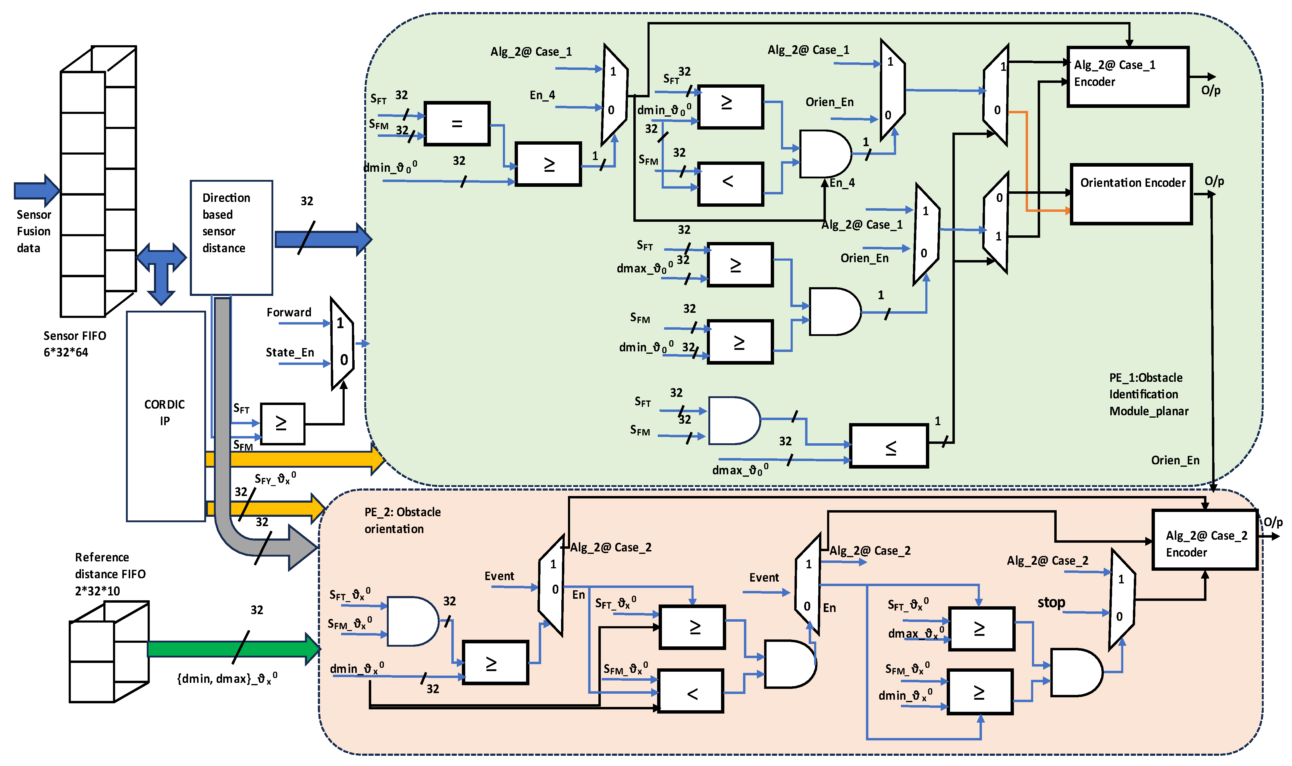
1. Initialize sensory distance and reference distances 2. Case (Obstacle) 3. State_1: if ((SFT && SFM) > dmax_ϑ0 0)? forward: State_2; 4. State_2: if ((SFT && SFM) ≤ dmax_ϑ0 0)? State_3: State_5; 5. State_3: if ((SFT == SFM) ≥ (dmin_ϑ0 0))? Alg_2@ Case_1: State_4; 6. State_4: if ((SFT ≥ dmin_ϑ0 0) && (SFM < dmin_ϑ0 0))? Alg_2@ Case_1: Orientation; 7. State_5: if ((SFT ≥ dmax _ϑ0 0) && (SFM ≥ dmin_ϑ0 0))? Alg_2@ Case_1: Orientation; 8. end case 9. Case (Orientation): 10. State_11: if ({SFT, SFM} @ ϑ ± 15 0, ±30 0, ±45 0, ±60 0, ±75 0) ≥ dmin)? Alg_2@ Case_2: State_12; 11. State_12: if ((SFT ≥ dmin_ϑ ± 15 0, ±30 0, ±45 0, ±60 0, ±75 0) && (SFM < dmin_ϑ ± 15 0, ±30 0, ±45 0, ±60 0, ±75 0))? Alg_2@ Case_2: State_13; 12. State_13: if ((SFT ≥ dmax_ϑ ± 15 0, ±30 0, ±45 0, ±60 0, ±75 0) && (SFM ≥ dmin_ϑ ± 15 0, ±30 0, ±45 0, ±60 0, ±75 0)), Alg_2@ Case_2; 13. end case |
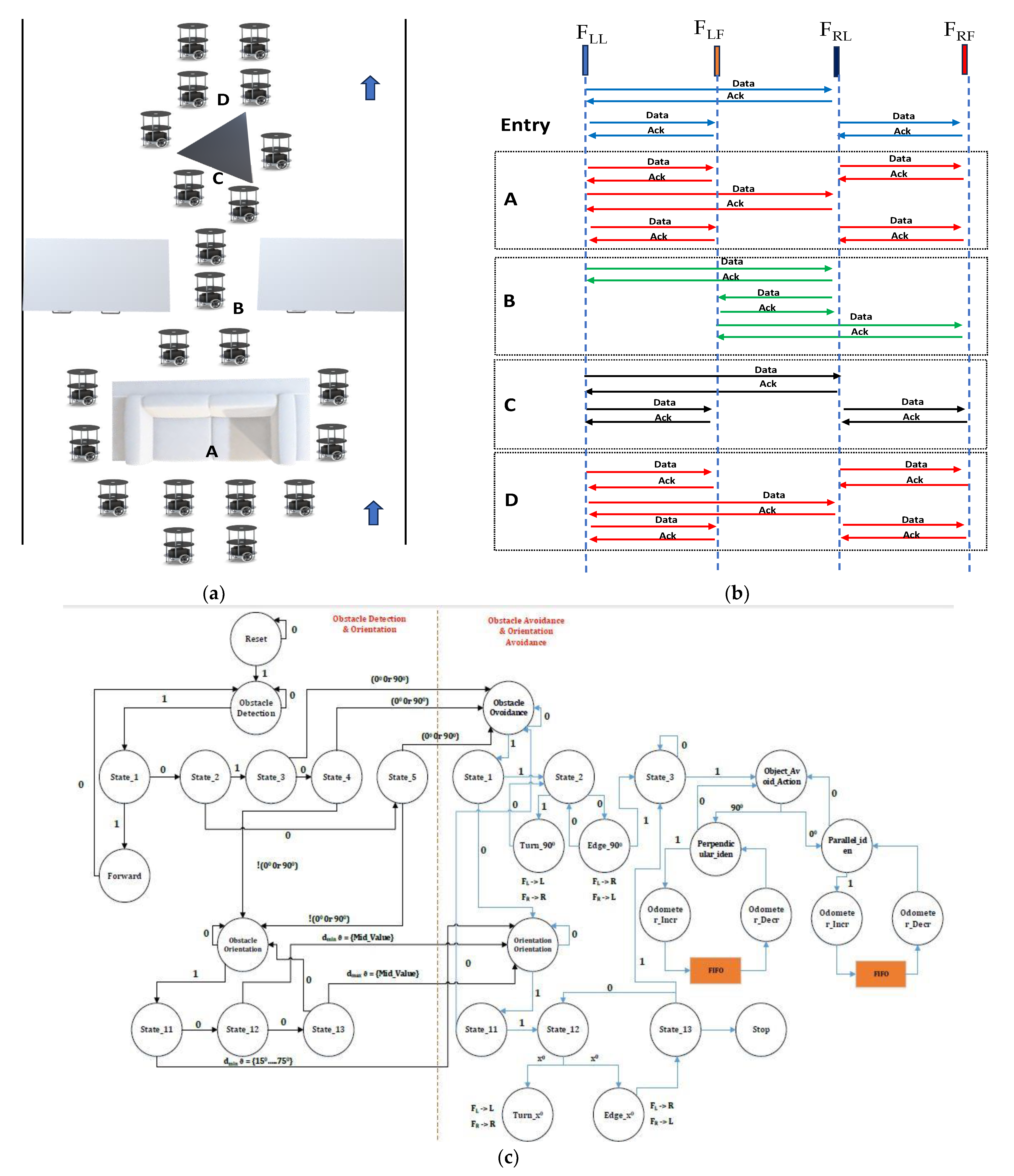
2.1.1. Hardware-Based Algorithm for Obstacle Avoidance of Indoor Polygonal Objects
| Algorithm 2: Pseudo code for obstacle avoidance |
|
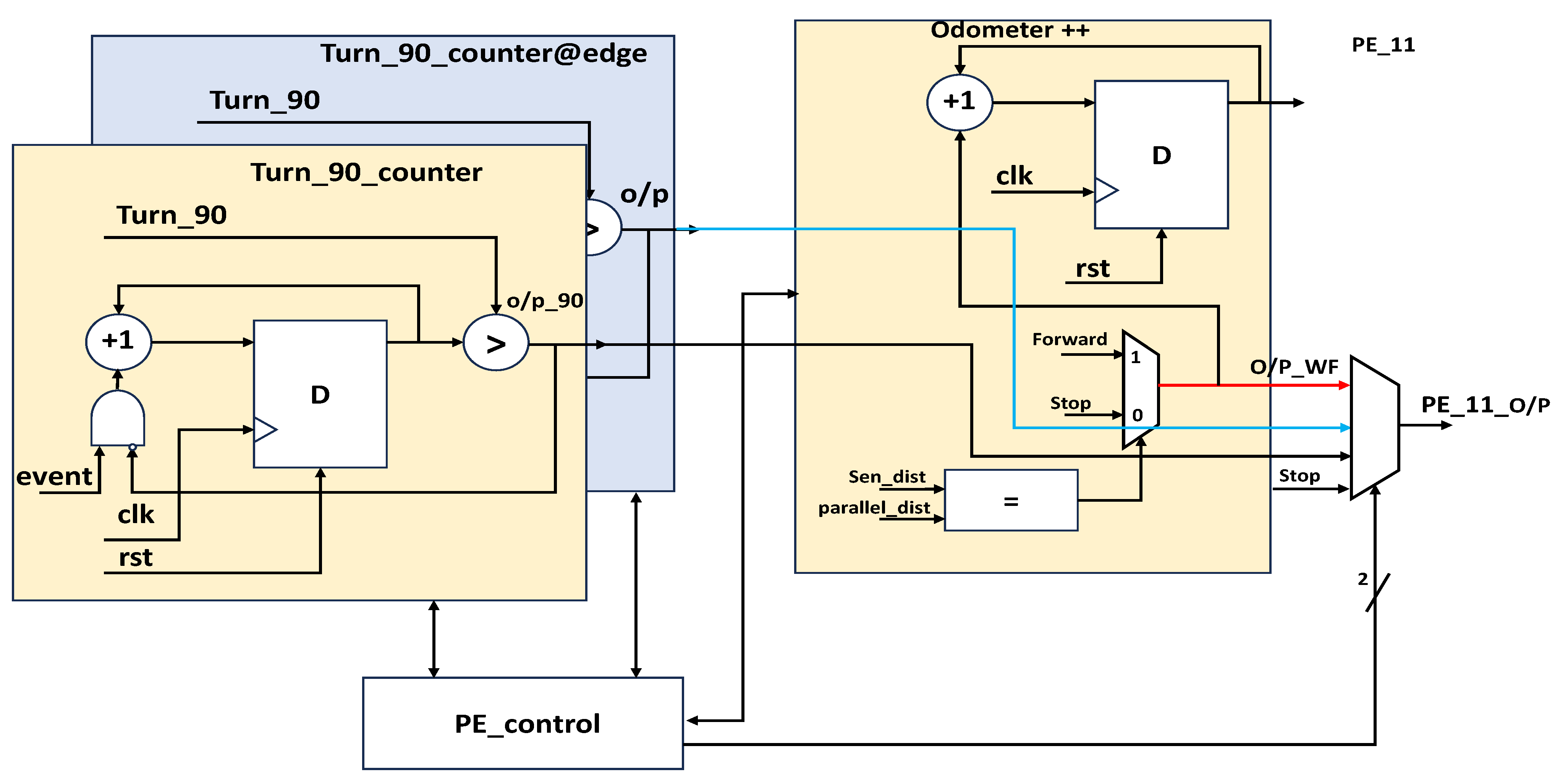
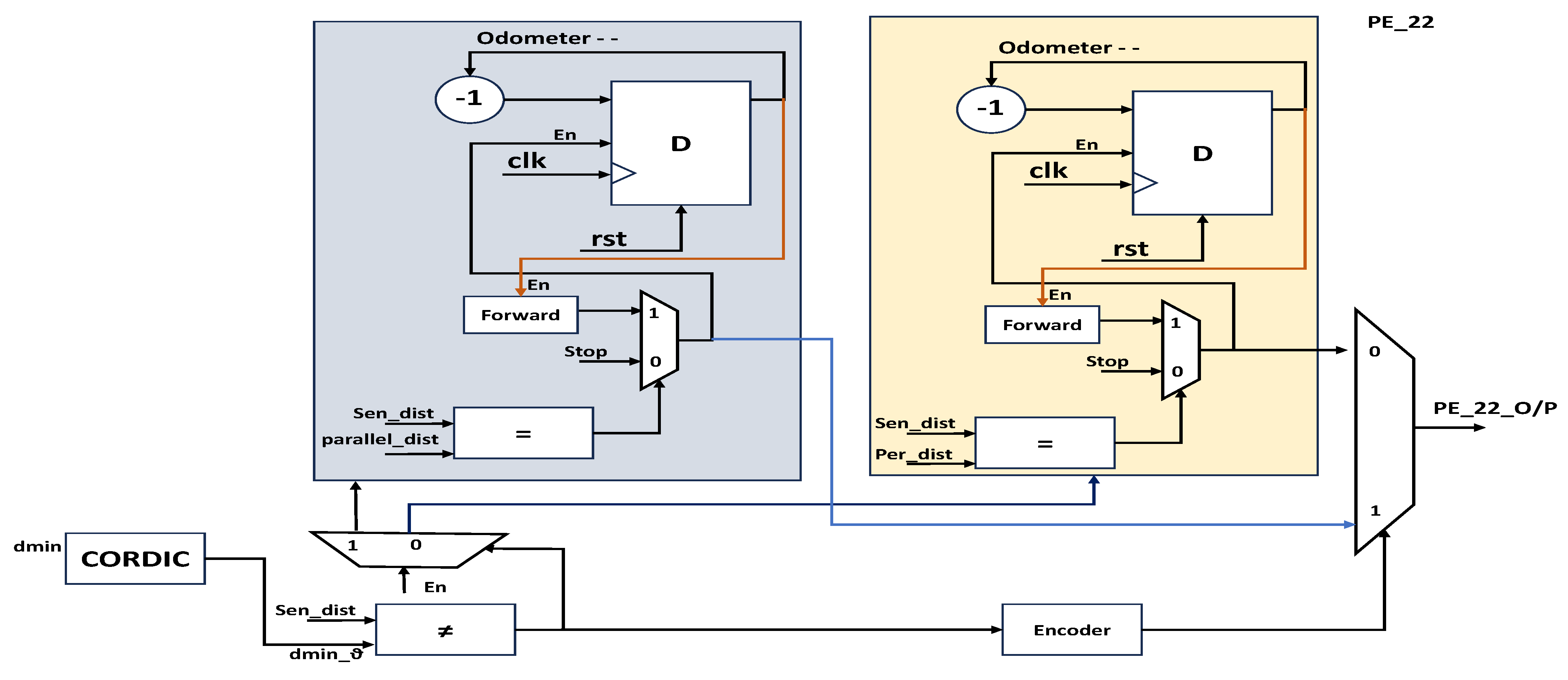
1. Initialize obstacle identification and orientation 2. Case_1 (Obstacle avoidance) 3. State_1: if ((SFT == SFM) ≥ (dmin_ϑ0 0))? State_2: Case_2. 4. State_2: turn ϑ90 0 FL -> L & FR -> R; Wall follow (odometer++), 5. turn @edge ϑ90 0, FL -> R & FR -> L. 6. State_3: if ((FL (SR)) && (FR (SL)) = dmin_ϑ0 0) 7. Wall follow in Parallel to object, Take turn @edge ϑ90 0 FL -> R & FR -> L, 8. else 9. Wall follow in Perpendicular to object, Take turn @edge ϑ90 0 FL -> R & FR -> L. 10. end 11. Forward (odometer - -), Take turn ϑ90 0 FL -> L & FR -> R, end case. 12. Case_2 (Obstacle avoidance _ Orientation): 13. State_11: if ((FL (SFT)) && (FR (SFT)) ≠ dmin_ϑ0 0)? State_12: Case_1. 14. State_12: turn w.r.t to object orient ϑx± 0, FL -> L & FR -> R; Wall follow (odometer++). 15. turn @edge ϑx± 0, FL -> R & FR -> L. 16. State_13: Repeat; State_3. 17. end case |
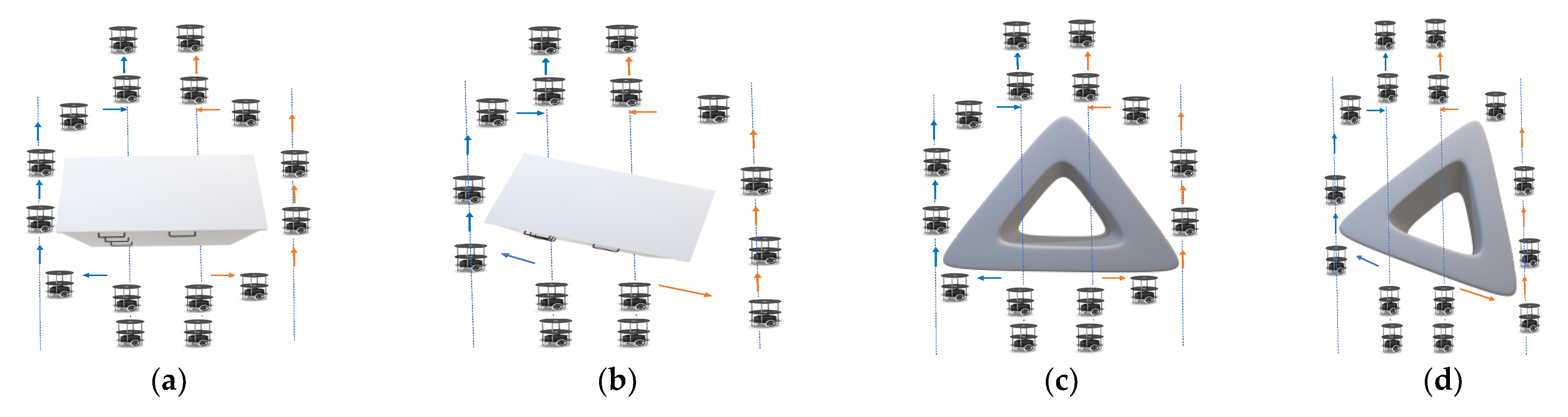
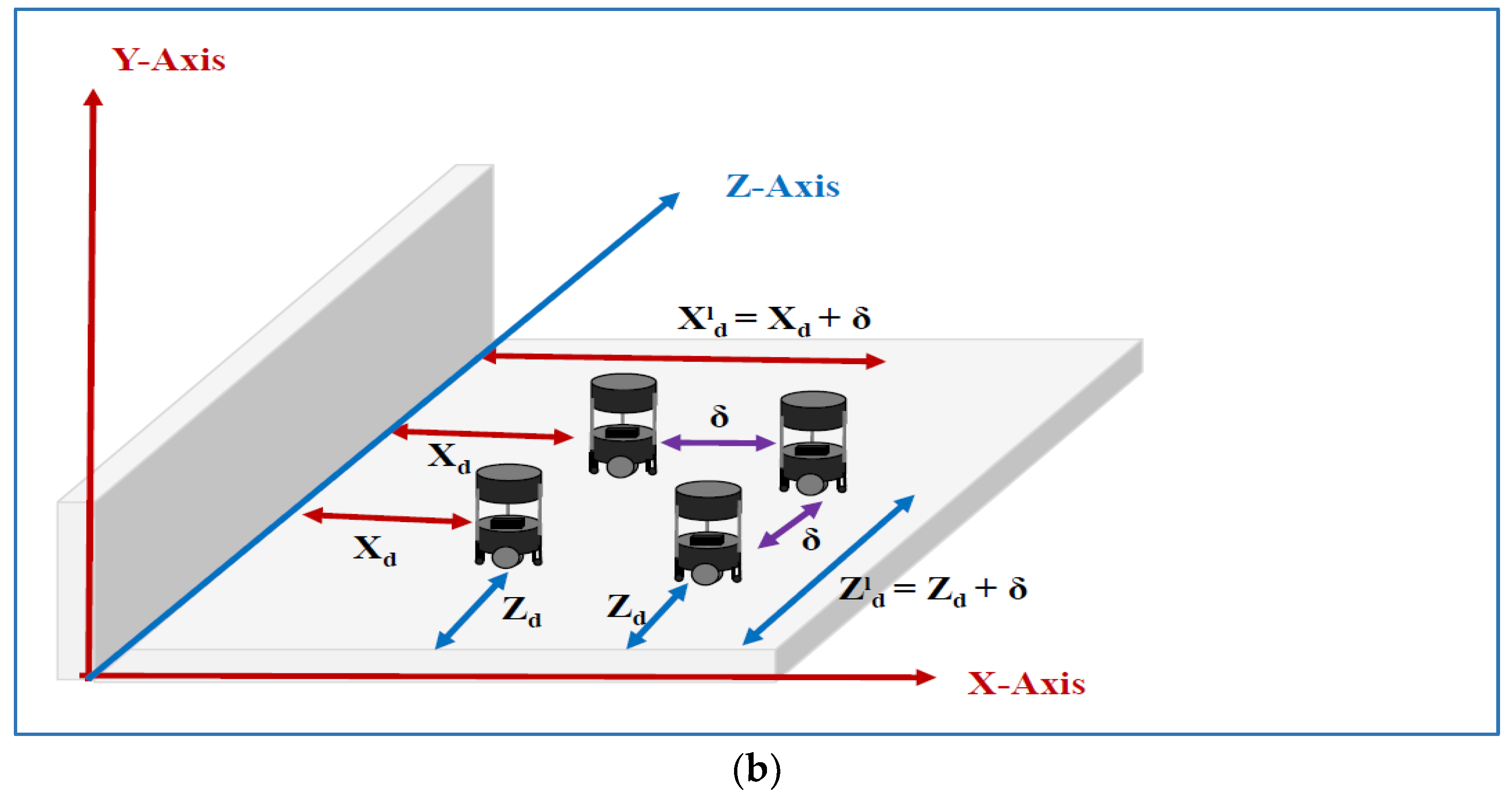
2.1.2. Formation and Deformation of Multi-Robot in Indoor Environment
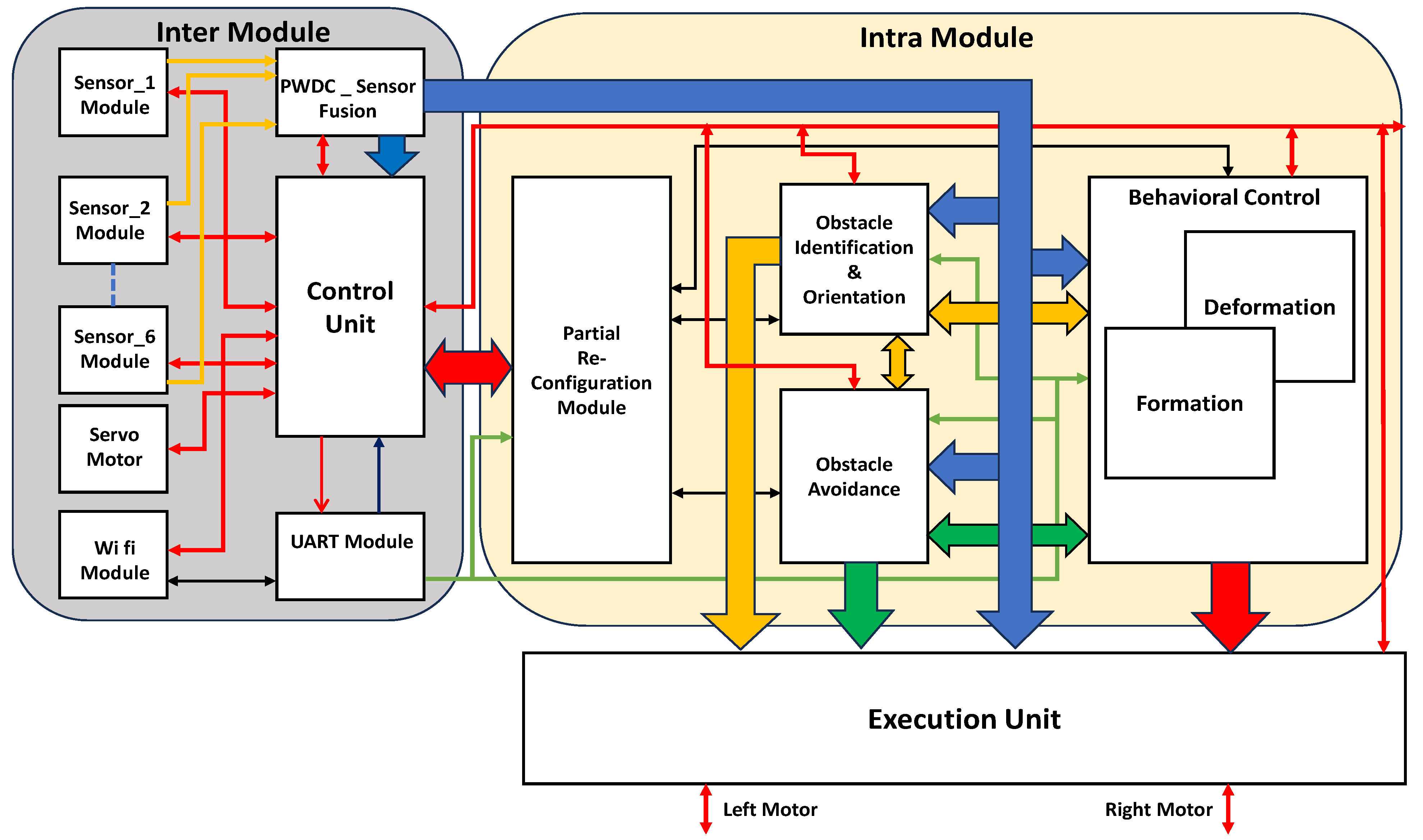
2.2. Hardware Schemes
2.2.1. Hardware Schemes of Obstacle Identification and Orientation
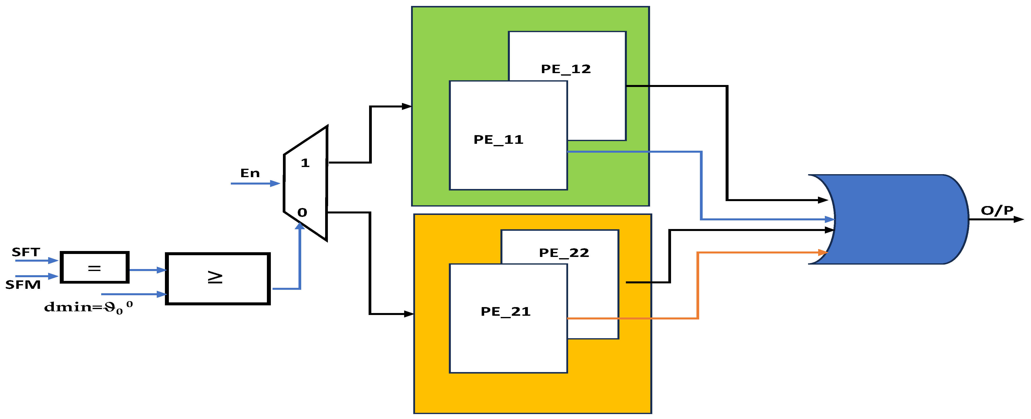
2.2.2. Hardware Schemes of Obstacle Avoidance for Distributed Multi-Robots
3. Results
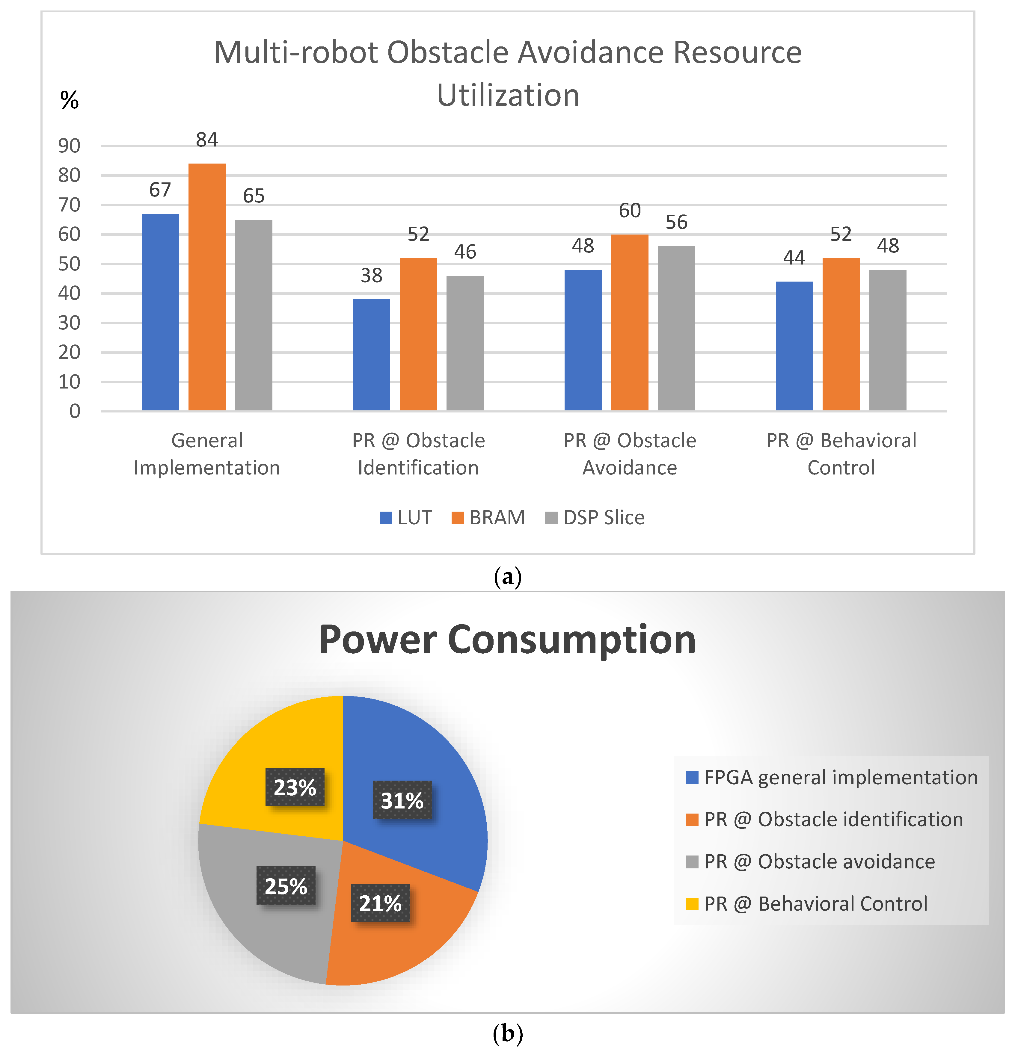
3.1. Resource Utilization
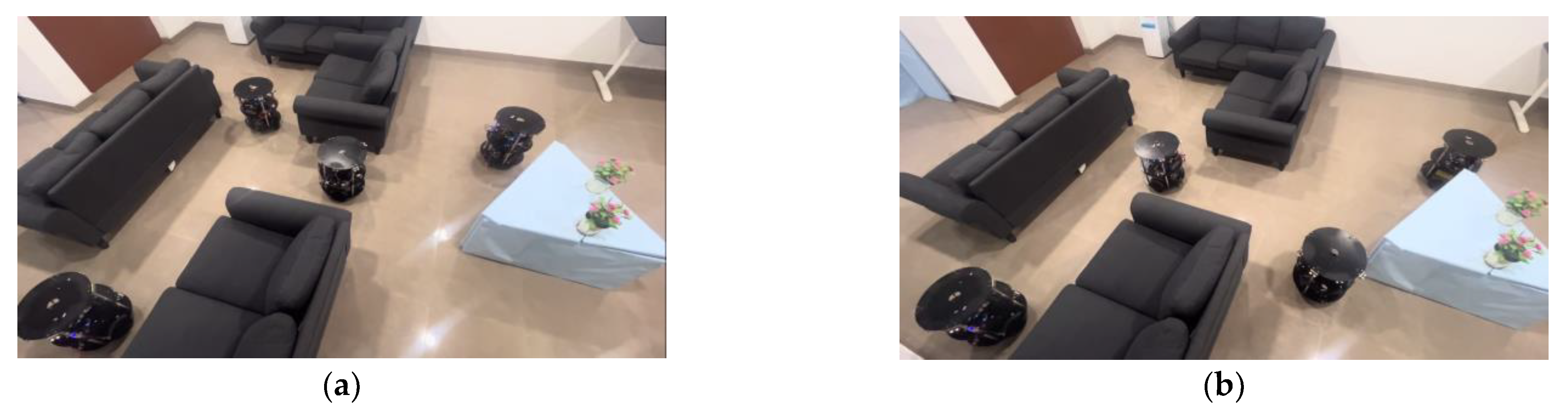
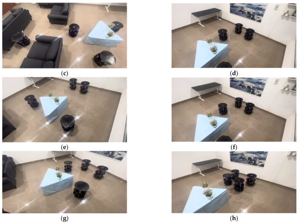
3.2. Experimental Results
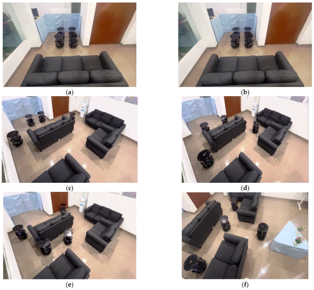
- Experimental results of multi-robot obstacle identification and avoidance
- Experimental results of multi-robot identification of oriented objects and avoidance.
4. Conclusions
Author Contributions
Funding
Institutional Review Board Statement
Informed Consent Statement
Data Availability Statement
Acknowledgments
Conflicts of Interest
References
- Available online: https://www.globenewswire.com/news-release/2023/08/18/2728081/0/en/Autonomous-Mobile-Robots-Market-Size-Share-Analysis-Growth-Trends-Forecasts-2023-2028.html (accessed on 23 May 2023).
- Alatise, M.B.; Hancke, G.P. A Review on Challenges of Autonomous Mobile Robot and Sensor Fusion Methods. IEEE Access 2020, 8, 39830–39846. [Google Scholar] [CrossRef]
- Darwish, S.M.; Salah, M.A.; Elzoghabi, A.A. Identifying Indoor Objects Using Neutrosophic Reasoning for Mobility Assisting Visually Impaired People. Appl. Sci. 2023, 13, 2150. [Google Scholar] [CrossRef]
- Gyenes, Z.; Bölöni, L.; Szádeczky-Kardoss, E.G. Can Genetic Algorithms Be Used for Real-Time Obstacle Avoidance for LiDAR-Equipped Mobile Robots? Sensors 2023, 23, 3039. [Google Scholar] [CrossRef] [PubMed]
- Ciuffreda, I.; Casaccia, S.; Revel, G.M. A Multi-Sensor Fusion Approach Based on PIR and Ultrasonic Sensors Installed on a Robot to Localise People in Indoor Environment. Sensors 2023, 23, 6963. [Google Scholar] [CrossRef] [PubMed]
- Raja, V.; Talwar, D.; Manchikanti, A.; Jha, S. Autonomous Navigation for Mobile Robots with Sensor Fusion Technology. In Industry 4.0 and Advanced Manufacturing; Springer: Singapore, 2023; p. 13. [Google Scholar]
- Han, J.; Kim, D.; Sunwoo, M.L.M. Enhanced Road Boundary and Obstacle Detection Using a Downward-Looking LIDAR Sensor. IEEE Trans. Veh. Technol. 2012, 61, 971–985. [Google Scholar] [CrossRef]
- Choset, H.; Lynch, K.M.; Hutchinson, S.; Kantor, G.A.; Burgard, W.; Kavraki, L.E.; Thrun, S. Bug Algorithms. In Principles of Robot Motion: Theory, Algorithms, and Implementations; MIT Press: Cambridge, MA, USA, 2005; pp. 17–38. [Google Scholar]
- Ren, Z.; Rathinam, S.; Likhachev, M.; Choset, H. Multi-Objective Safe-Interval Path Planning with Dynamic Obstacles. IEEE Robot. Autom. Lett. 2022, 7, 8154–8161. [Google Scholar] [CrossRef]
- Zhang, Z.; Hajieghrary, H.; Dean, E.; Åkesson, K. Prescient Collision-Free Navigation of Mobile Robots with Iterative Multimodal Motion Prediction of Dynamic Obstacles. IEEE Robot. Autom. Lett. 2023, 8, 5488–5495. [Google Scholar] [CrossRef]
- Divya Vani, G.; Karumuri, S.R.; Chinnaiah, M.C. Hardware Schemes for Autonomous Navigation of Cooperative-type Multi-robot in Indoor Environment. J. Inst. Eng. India Ser. B 2022, 103, 449–460. [Google Scholar] [CrossRef]
- Wang, Q.; Li, J.; Yang, L.; Yang, Z.; Li, P.; Xia, G. Distributed Multi-Mobile Robot Path Planning and Obstacle Avoidance Based on ACO–DWA in Unknown Complex Terrain. Electronics 2022, 11, 2144. [Google Scholar] [CrossRef]
- Bai, C.; Yan, P.; Pan, W.; Guo, J. Learning-Based Multi-Robot Formation Control with Obstacle Avoidance. IEEE Trans. Intell. Transp. Syst. 2022, 23, 11811–11822. [Google Scholar] [CrossRef]
- Aranda, M.; Sanchez, J.; Ramon, J.A.C.; Mezouar, Y. Robotic Motion Coordination Based on a Geometric Deformation Measure. IEEE Syst. J. 2022, 16, 3689–3699. [Google Scholar] [CrossRef]
- Choi, J.; Song, Y.; Lim, S.; Kwon, C.; Oh, H. Decentralized Multi-Subgroup Formation Control with Connectivity Preservation and Collision Avoidance. IEEE Access 2020, 8, 71525–71534. [Google Scholar] [CrossRef]
- Vyas, P.; Vachhani, L.; Sridharan, K.; Pudi, V. CORDIC-Based Azimuth Calculation and Obstacle Tracing via Optimal Sensor Placement on a Mobile Robot. IEEE/ASME Trans. Mechatron. 2016, 21, 2317–2329. [Google Scholar] [CrossRef]
- Vundurthy, B.; Sridharan, K. Protecting an Autonomous Delivery Agent Against a Vision-Guided Adversary: Algorithms and Experimental Results. IEEE Trans. Ind. Inform. 2020, 16, 5667–5679. [Google Scholar] [CrossRef]
- Vundurthy, B.; Sridharan, K. Multiagent Gathering with Collision Avoidance and a Minimax Distance Criterion—Efficient Algorithms and Hardware Realization. IEEE Trans. Ind. Inform. 2019, 15, 699–709. [Google Scholar] [CrossRef]
- G, D.V.; Karumuri, S.R.; C, C.M.; Lam, S.-K.; Narambhatlu, J.; Dubey, S. Hardware-Efficient Scheme for Trailer Robot Parking by Truck Robot in an Indoor Environment with Rendezvous. Sensors 2023, 23, 5097. [Google Scholar] [CrossRef] [PubMed]
- Wan, Z.; Yu, B.; Li, T.Y.; Tang, J.; Zhu, Y.; Wang, Y.; Raychowdhury, A.; Liu, S. A Survey of FPGA-Based Robotic Computing. IEEE Circuits Syst. Mag. 2022, 21, 48–74. [Google Scholar] [CrossRef]
- Meher, P.K.; Valls, J.; Juang, T.-B.; Sridharan, K.; Maharatna, K. 50 Years of CORDIC: Algorithms, Architectures, and Applications. IEEE Trans. Circuits Syst. I Regul. Pap. 2009, 56, 1893–1907. [Google Scholar] [CrossRef]
- Divya Vani, G.; Chinnaiah, M.; Karumuri, S.R. Hardware Scheme for Autonomous Docking Algorithm using FPGA based Mobile Robot. In Proceedings of the 2018 8th International Symposium on Embedded Computing and System Design (ISED), Cochin, India, 13–15 December 2018; pp. 110–115. [Google Scholar]
- Tadigotla, V.; Sliger, L.; Commuri, S. FPGA implementation of dynamic run-time behavior reconfiguration in robots. In Proceedings of the 2006 IEEE Conference on Computer Aided Control System Design, 2006 IEEE International Conference on Control Applications, 2006 IEEE International Symposium on Intelligent Control, Munich, Germany, 4–6 October 2006; pp. 1220–1225. [Google Scholar]
- Vipin, K.; Fahmy, S.A. ZyCAP: Efficient Partial Reconfiguration Management on the Xilinx Zynq. IEEE Embed. Syst. Lett. 2014, 6, 41–44. [Google Scholar] [CrossRef]
- Vipin, K.; Gray, J.; Kapre, N. Enabling partial reconfiguration and low latency routing using segmented FPGA NoCs. In Proceedings of the 2017 27th International Conference on Field Programmable Logic and Applications (FPL), Ghent, Belgium, 4–8 September 2017; pp. 1–8. [Google Scholar]
- Hu, C.; Ning, B.; Xu, M.; Gu, Q. An Experience Aggregative Reinforcement Learning with Multi-Attribute Decision-Making for Obstacle Avoidance of Wheeled Mobile Robot. IEEE Access 2020, 8, 108179–108190. [Google Scholar] [CrossRef]
- Wen, S.; Zheng, W.; Zhu, J.; Li, X.; Chen, S. Elman Fuzzy Adaptive Control for Obstacle Avoidance of Mobile Robots Using Hybrid Force/Position Incorporation. IEEE Trans. Syst. Man Cybern. Part C Appl. Rev. 2012, 42, 603–608. [Google Scholar]
- Mata-Machuca, J.L.; Zarazua, L.F.; Aguilar-López, R. Experimental Verification of the Leader-Follower Formation Control of Two Wheeled Mobile Robots with Obstacle Avoidance. IEEE Lat. Am. Trans. 2021, 19, 1417–1424. [Google Scholar] [CrossRef]
- Guo, B.; Guo, N.; Cen, Z. Obstacle Avoidance with Dynamic Avoidance Risk Region for Mobile Robots in Dynamic Environments. IEEE Robot. Autom. Lett. 2022, 7, 5850–5857. [Google Scholar] [CrossRef]
- Lu, Q.; Zhang, D.; Ye, W.; Fan, J.; Liu, S.; Su, C.-Y. Targeting Posture Control with Dynamic Obstacle Avoidance of Constrained Uncertain Wheeled Mobile Robots Including Unknown Skidding and Slipping. IEEE Trans. Syst. Man Cybern. Syst. 2021, 51, 6650–6659. [Google Scholar] [CrossRef]


| Module | LUT | BRAM | DSP Slice |
|---|---|---|---|
| Obstacle Identification and Orientation | 3724 | 18 | 8 |
| Obstacle Avoidance | 8416 | 28 | 30 |
| Interfacing Modules (sensors, motors, communication, Xilinx IP cores) | 6852 | 24 | 36 |
| Control Unit and PWDC Sensor Fusion | 4468 | 20 | 42 |
| Partial Reconfiguration Module | 5586 | 12 | 14 |
| Behavioral Control Module | 6628 | 16 | 12 |
| Total | 35,674 | 134 | 142 |
| Reference Papers | Sensory Approach | Algorithm | Hardware | Pros | Cons | |
|---|---|---|---|---|---|---|
| Method | Fusion | |||||
| [26] | RGB-D camera | X | Multi-attribute decision making | CPU | Reinforcement learning (RL) | Limited to simulation |
| [27] | Virtual force | X | Hybrid force/ position | CPU | Fuzzy adaptive controller | Limited to simulation |
| [28] | LIDAR | X | Multi-robot collision avoidance | CPU | Leader–follower formation control | Higher power consumption |
| [29] | - | X | Nonlinear model predictive control | CPU | Dynamic obstacle avoidance | Limited to simulation |
| [30] | _ | X | Dynamic obstacle avoidance of differential-drive wheeled mobile robot | CPU | Skidding and slipping analysis in obstacle avoidance | Limited to simulation |
| [11] | Ultrasonic sensor | X | Centralized obstacle avoidance | FPGA | Hardware schemes for centralized multi-mobile robot’s obstacle avoidance | Partial reconfiguration not part of the hardware design |
| Proposed | Ultrasonic sensor | √ | Centralization at formation and distribution at deformation method for obstacle avoidance | FPGA | Partial reconfiguration-based hardware schemes are a novel approach | Velocity-based obstacle avoidance will be addressed in future |
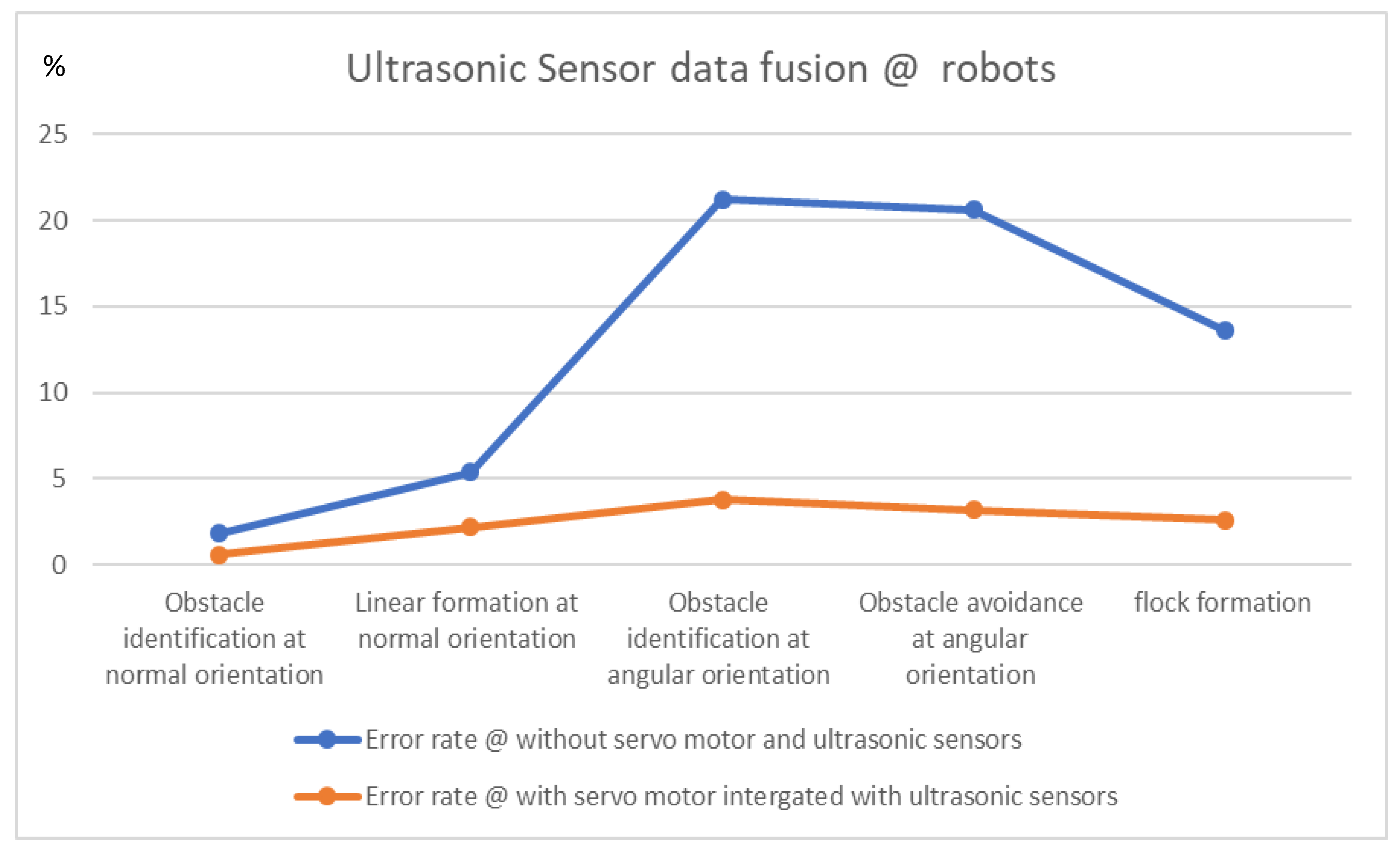
| Environment Scenario | Ultrasonic Sensor Data Fusion | Capture Sensory Data Fusion @ Positive Rate | Error Rate |
|---|---|---|---|
| A | # Obstacle identification at normal orientation | 98.2% | 1.8% |
| $ Obstacle identification at normal orientation | 99.4% | 0.6% | |
| B | # Linear formation at normal orientation | 94.6% | 5.4% |
| $ Linear formation at normal orientation | 97.8% | 2.2% | |
| C | # Obstacle identification at angular orientation | 78.8% | 21.2% |
| $ Obstacle identification at angular orientation | 96.2% | 3.8% | |
| Transmission C to D | # Obstacle avoidance at angular orientation | 79.4% | 20.6% |
| $ Obstacle avoidance at angular orientation | 96.8% | 3.2% | |
| D | # flock formation | 86.4% | 13.6% |
| $ flock formation | 97.4% | 2.6% |
Disclaimer/Publisher’s Note: The statements, opinions and data contained in all publications are solely those of the individual author(s) and contributor(s) and not of MDPI and/or the editor(s). MDPI and/or the editor(s) disclaim responsibility for any injury to people or property resulting from any ideas, methods, instructions or products referred to in the content. |
© 2023 by the authors. Licensee MDPI, Basel, Switzerland. This article is an open access article distributed under the terms and conditions of the Creative Commons Attribution (CC BY) license (https://creativecommons.org/licenses/by/4.0/).
Share and Cite
Basha, M.; Siva Kumar, M.; Chinnaiah, M.C.; Lam, S.-K.; Srikanthan, T.; Janardhan, N.; Hari Krishna, D.; Dubey, S. A Versatile Approach to Polygonal Object Avoidance in Indoor Environments with Hardware Schemes Using an FPGA-Based Multi-Robot. Sensors 2023, 23, 9480. https://doi.org/10.3390/s23239480
Basha M, Siva Kumar M, Chinnaiah MC, Lam S-K, Srikanthan T, Janardhan N, Hari Krishna D, Dubey S. A Versatile Approach to Polygonal Object Avoidance in Indoor Environments with Hardware Schemes Using an FPGA-Based Multi-Robot. Sensors. 2023; 23(23):9480. https://doi.org/10.3390/s23239480
Chicago/Turabian StyleBasha, Mudasar, Munuswamy Siva Kumar, Mangali Chinna Chinnaiah, Siew-Kei Lam, Thambipillai Srikanthan, Narambhatla Janardhan, Dodde Hari Krishna, and Sanjay Dubey. 2023. "A Versatile Approach to Polygonal Object Avoidance in Indoor Environments with Hardware Schemes Using an FPGA-Based Multi-Robot" Sensors 23, no. 23: 9480. https://doi.org/10.3390/s23239480