
Self-Position Determination Based on Array Signal Subspace Fitting under Multipath Environments

Abstract
:1. Introduction
- (1)
- The K-means clustering algorithm is applied to identify NLOS components from the multipath signals with a distance comparison function. The intersection of bearing lines, which is nearest to the adjacent points, is selected as the initial position estimation. The angles formed by the emitters and initial position are considered as reference angles. The distance comparison function is established using the Euclidean distance between the reference angle and DOA estimation results for each emitter.
- (2)
- The SSF cost function for suppressing NLOS components is established to obtain a precise estimation result. The NLOS components of the signal subspace are suppressed with orthogonal projection. The suppressed signal subspace fitting is obtained using the least squares (LS) equation and the orthogonal projection is incorporated into the matrix in the SSF cost function.
- (3)
- The local grid search of self-position determination is proposed to reduce the computational complexity of the cost function. On the basis of the initial position estimation, the vehicle position is roughly determined. The accurate position determination can be obtained using the cost function calculation on the local grid points distributed around the initial estimation.
- (4)
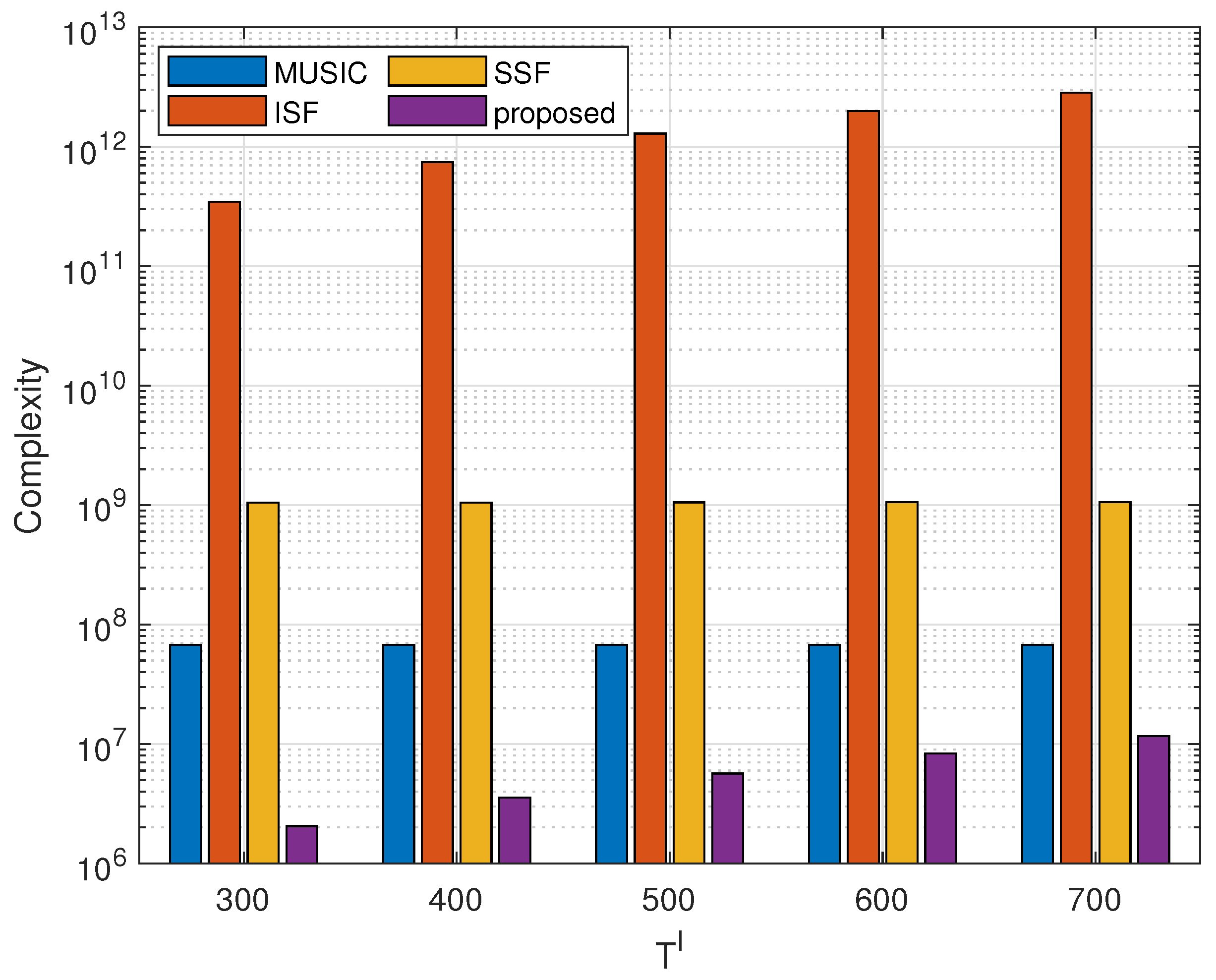
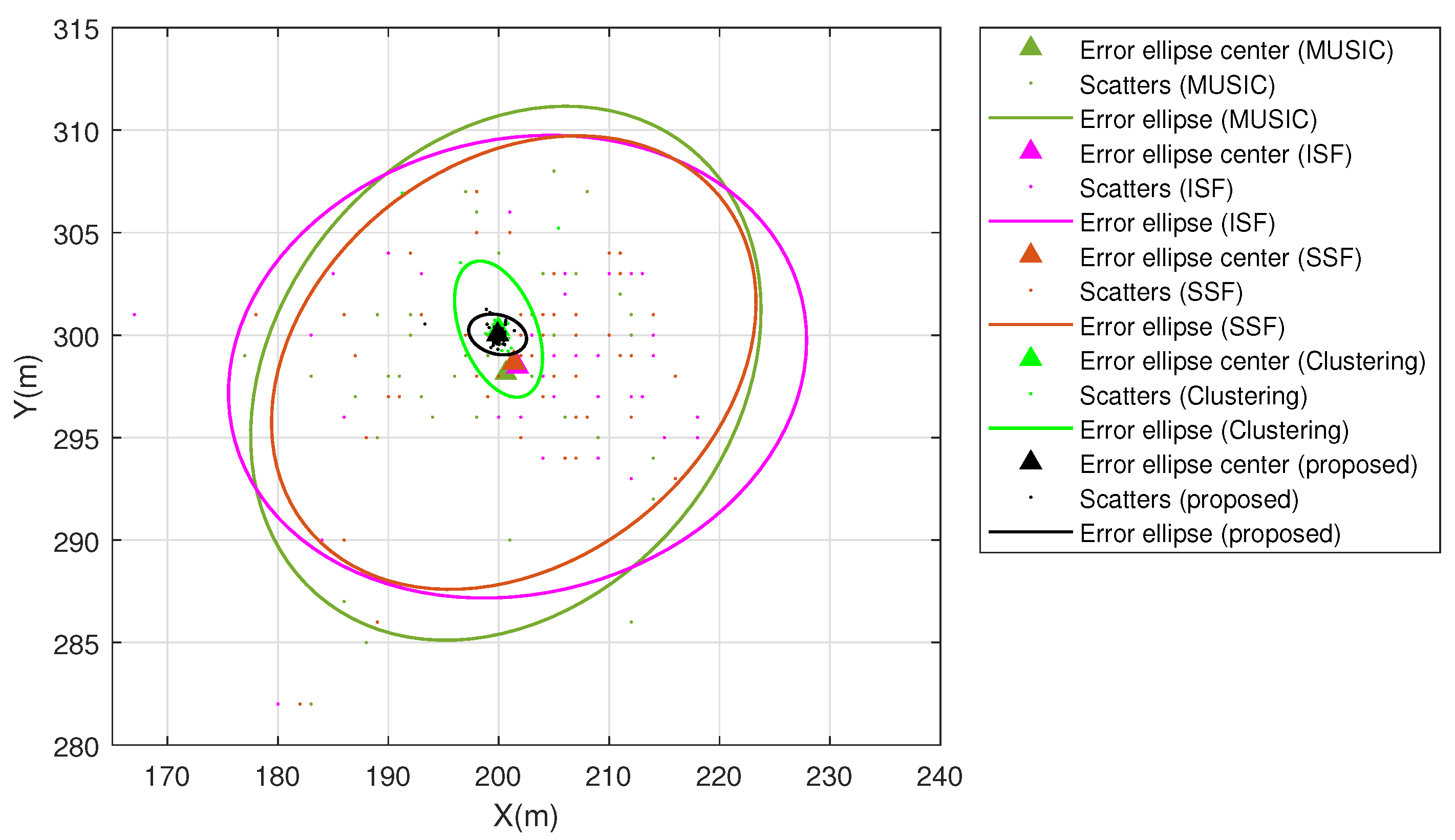
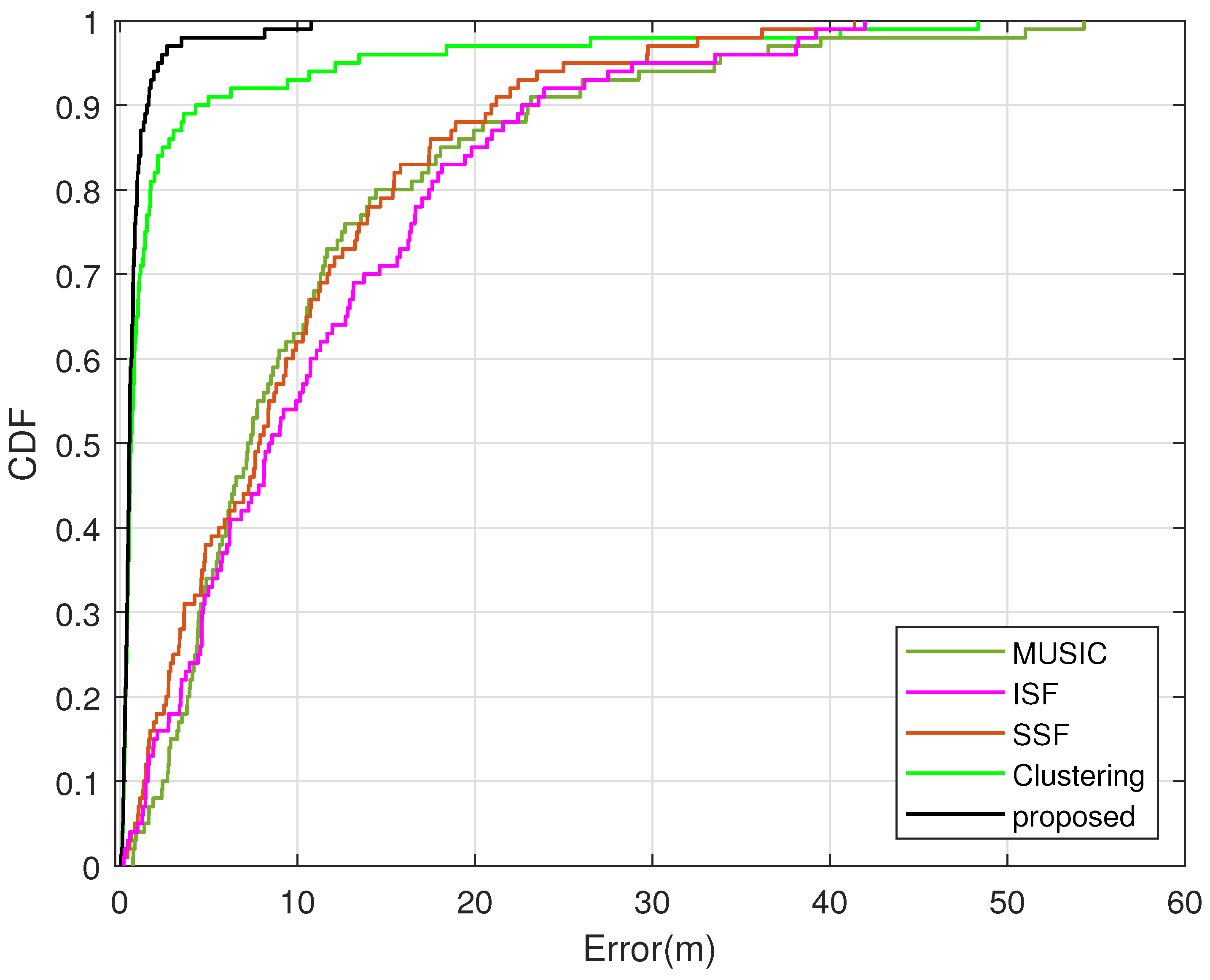
- The simulation results show that the proposed method has low computational complexity and high position estimation precision. The numerical analysis shows that the computational complexity of the proposed method is at least lower than MUSIC, ISF and SSF. A cumulative distribution function (CDF) analysis demonstrates that 85 percent of the estimated deviation values for the proposed method are smaller than the clustering algorithm and less than MUSIC, ISF and SSF under multipath environments.
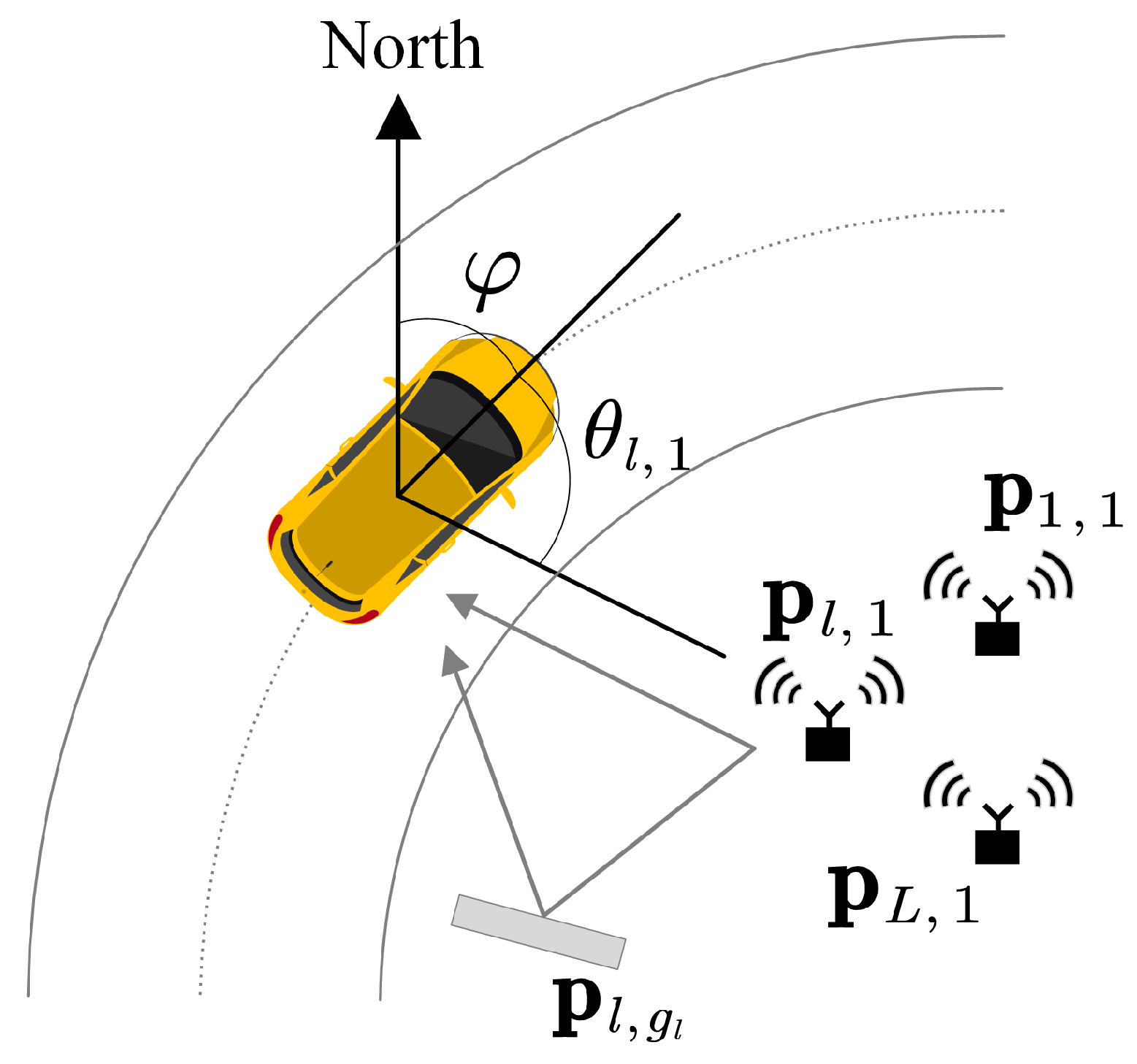
2. Signal Model
3. The Proposed Method
3.1. DOA Estimation of Multipath Signals
3.2. Discrimination of NLOS Components with Clustering Algorithm
3.3. NLOS Data Suppression with Orthogonal Projection
3.4. Self-Position Determination with Array Signal Subspace Fitting
3.4.1. Grid Search Model
3.4.2. Signal Subspace Fitting
| Algorithm 1 Self-Position Determination Based on Array Signal Subspace Fitting under Multipath Environments |
|
4. Performance Analysis
4.1. Complexity Analysis
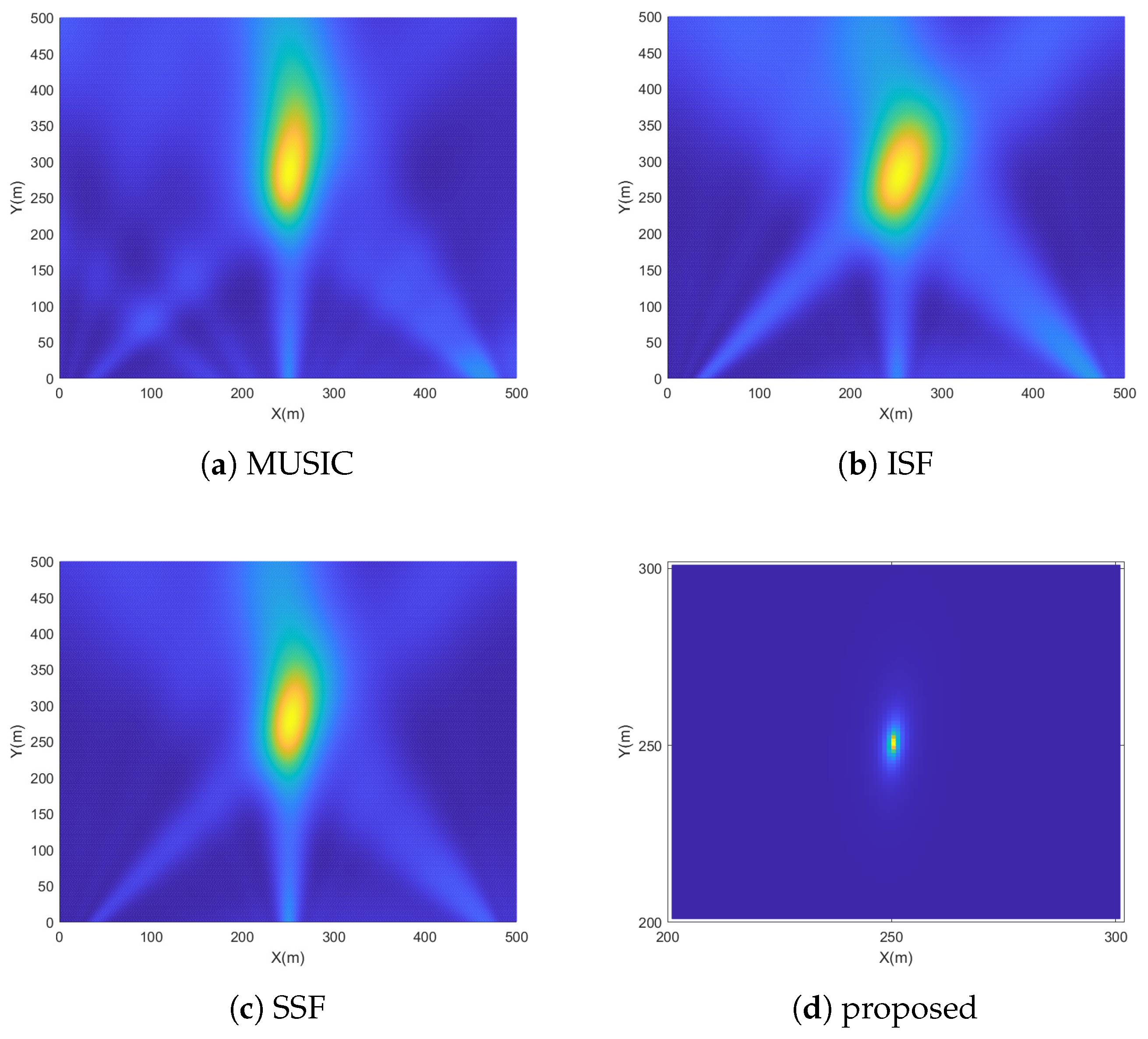
4.2. Simulation Results
5. Conclusions
Author Contributions
Funding
Institutional Review Board Statement
Informed Consent Statement
Data Availability Statement
Conflicts of Interest
Abbreviations
| CVIS | Cooperative Vehicle Infrastructure Systems |
| SSF | Signal Subspace Fitting |
| ISF | Initial Signal Fitting |
| NLOS | Non-Line-Of-Sight |
| LOS | Line-Of-Sight |
| ULA | Uniform Linear Array |
| DOA | Direction Of Arrival |
| MUSIC | Multiple Signal Classification |
| LS | Least Squares |
| SNR | Signal-To-Noise Ratio |
| CDF | Cumulative Distribution Function |
| RMSE | Root Mean Square Error |
References
- Jia, M.; Khalife, J.; Kassas, Z.M. Performance Analysis of Opportunistic ARAIM for Navigation with GNSS Signals Fused with Terrestrial Signals of Opportunity. IEEE Trans. Intell. Transp. Syst. 2023, 24, 10587–10602. [Google Scholar] [CrossRef]
- Zhu, J.; Zhou, H.; Wang, Z.; Yang, S. Improved Multi-Sensor Fusion Positioning System Based on GNSS/LiDAR/Vision/IMU with Semi-Tight Coupling and Graph Optimization in GNSS Challenging Environments. IEEE Access 2023, 11, 95711–95723. [Google Scholar] [CrossRef]
- Tang, C.; Wang, Y.; Zhang, L.; Zhang, Y. GNSS/Inertial Navigation/Wireless Station Fusion UAV 3-D Positioning Algorithm with Urban Canyon Environment. IEEE Sens. J. 2022, 22, 18771–18779. [Google Scholar] [CrossRef]
- Sun, Y.; Cao, L.; Li, S.; Deng, Z. G5GIM: Integrity Monitoring for GNSS/5G Integrated Navigation of Urban Vehicles. IEEE Trans. Instrum. Meas. 2023, 72, 1–13. [Google Scholar] [CrossRef]
- Zhang, P.; Tian, D.; Zhou, J.; Duan, X.; Sheng, Z.; Zhao, D.; Cao, D. Joint Optimization of Platoon Control and Resource Scheduling in Cooperative Vehicle-Infrastructure System. IEEE Trans. Intell. Veh. 2023, 8, 3629–3646. [Google Scholar] [CrossRef]
- Wang, J.; Shao, Y.; Ge, Y.; Yu, R. A Survey of Vehicle to Everything (V2X) Testing. Sensors 2019, 19, 334. [Google Scholar] [CrossRef]
- Han, X.; Tian, D.; Sheng, Z.; Duan, X.; Zhou, J.; Hao, W.; Long, K.; Xhen, M.; Leung, C.M. Reliability-Aware Joint Optimization for Cooperative Vehicular Communication and Computing. IEEE Trans. Intell. Transp. Syst. 2020, 22, 5437–5446. [Google Scholar] [CrossRef]
- Gan, L.; Jiang, W.; Chen, Q.; Li, X.; Zhou, Z.; Gong, S. Method to Estimate Antenna Mode Radar Cross Section of Large-Scale Array Antennas. IEEE Trans. Antennas Propag. 2021, 69, 7029–7034. [Google Scholar] [CrossRef]
- Yao, J.; Zhao, C.; Bai, J.; Ren, Y.; Wang, Y.; Miao, J. Satellite Interference Source Direction of Arrival (DOA) Estimation Based on Frequency Domain Covariance Matrix Reconstruction. Sensors 2023, 23, 7575. [Google Scholar] [CrossRef] [PubMed]
- Li, J.; Li, P.; Li, P.; Tang, L.; Zhang, X.; Wu, Q. Self-Position Awareness Based on Cascade Direct Localization over Multiple Source Data. IEEE Trans. Intell. Transp. Syst. 2022, 1–9. [Google Scholar] [CrossRef]
- Cao, Z.; Li, P.; Li, J.; Zhang, X.; Wu, Q. Direct Self-Position Awareness Based on Array-Sensing Multiple Source Data Fitting. In Proceedings of the 2023 4th Information Communication Technologies Conference (ICTC), Nanjing, China, 17–19 May 2023; pp. 213–217. [Google Scholar]
- Hao, K.; Wan, Q. Sparse Bayesian Inference-Based Direct Off-Grid Position Determination in Multipath Environments. IEEE Wirel. Commun. Lett. 2021, 10, 1148–1152. [Google Scholar] [CrossRef]
- Zhang, L.; Chen, M.; Wang, X.; Wang, Z. TOA Estimation of Chirp Signal in Dense Multipath Environment for Low-Cost Acoustic Ranging. IEEE Trans. Instrum. Meas. 2019, 68, 13011–13028. [Google Scholar] [CrossRef]
- Liu, Y.; Tan, Z.-W.; Khong, A.W.H.; Liu, H. An Iterative Implementation-Based Approach for Joint Source Localization and Association Under Multipath Propagation Environments. IEEE Trans. Signal Process. 2023, 71, 121–135. [Google Scholar] [CrossRef]
- Van Marter, J.P.; Dabak, A.G.; Al-Dhahir, N.; Torlak, M. Support Vector Regression for Bluetooth Ranging in Multipath Environments. IEEE Internet Things J. 2023, 10, 11533–11546. [Google Scholar] [CrossRef]
- Aubry, A.; De Maio, A.; Foglia, G.; Orlando, D. Diffuse Multipath Exploitation for Adaptive Radar Detection. IEEE Trans. Signal Process. 2015, 63, 1268–1281. [Google Scholar] [CrossRef]
- Hayvaci, H.T.; De Maio, A.; Erricolo, D. Diversity in Receiving Strategies Based on Time-Delay Analysis in the Presence of Multipath. In Proceedings of the 2011 IEEE RadarCon (RADAR), Kansas City, MO, USA, 23–27 May 2011; pp. 1040–1045. [Google Scholar]
- Hayvaci, H.T.; De Maio, A.; Erricolo, D. Performance Analysis of Diverse GLRT Detectors in the Presence of Multipath. In Proceedings of the 2012 IEEE Radar Conference, Atlanta, GA, USA, 7–11 May 2012; pp. 902–906. [Google Scholar]
- Rong, Y.; Aubry, A.; De Maio, A.; Tang, M. Diffuse Multipath Exploitation for Adaptive Detection of Range Distributed Targets. IEEE Trans. Signal Process. 2020, 68, 1197–1212. [Google Scholar] [CrossRef]
- Dun, H.; Tiberius, C.C.J.M.; Janssen, G.J.M. Positioning in a Multipath Channel Using OFDM Signals with Carrier Phase Tracking. IEEE Access 2020, 8, 13011–13028. [Google Scholar] [CrossRef]
- Yang, Z.; Stoica, P.; Tang, J. Source Resolvability of Spatial-Smoothing-Based Subspace Methods: A Hadamard Product Perspective. IEEE Trans. Signal Process. 2019, 67, 2543–2553. [Google Scholar] [CrossRef]
- Carotenuto, V.; De Maio, A. A Clustering Approach for Jamming Environment Classification. IEEE Trans. Aerosp. Electron. Syst. 2021, 57, 1903–1918. [Google Scholar] [CrossRef]
- Li, J.; He, Y.; Zhang, X.; Wu, Q. Simultaneous Localization of Multiple Unknown Emitters Based on UAV Monitoring Big Data. IEEE Trans. Ind. Inform. 2021, 17, 6303–6313. [Google Scholar] [CrossRef]
- Guo, X.; Chen, Z.; Hu, X.; Li, X. Multi-Source Localization Using Time of Arrival Self-Clustering Method in Wireless Sensor Networks. IEEE Access 2019, 7, 82110–82121. [Google Scholar] [CrossRef]
- Zhang, Y.; Ye, Z. Efficient Method of DOA Estimation for Uncorrelated and Coherent Signals. IEEE Antennas Wirel. Propag. Lett. 2008, 7, 799–802. [Google Scholar] [CrossRef]
- Xu, X.; Ye, Z.; Zhang, Y.; Chang, C. A Deflation Approach to Direction of Arrival Estimation for Symmetric Uniform Linear Array. IEEE Antennas Wirel. Propag. Lett. 2006, 5, 486–489. [Google Scholar] [CrossRef]
- Zhang, X.; He, Z.; Liao, B.; Yang, Y.; Zhang, J.; Zhang, X. Flexible Array Response Control via Oblique Projection. IEEE Trans. Signal Process. 2019, 67, 3126–3139. [Google Scholar] [CrossRef]
- Tao, H.; Xin, J.; Wang, J.; Zheng, N.; Sano, A. Two-Dimensional Direction Estimation for a Mixture of Noncoherent and Coherent Signals. IEEE Trans. Signal Process. 2015, 63, 318–333. [Google Scholar] [CrossRef]
- Tirer, T.; Weiss, A.J. High Resolution Direct Position Determination of Radio Frequency Sources. IEEE Signal Process. Lett. 2016, 23, 192–196. [Google Scholar] [CrossRef]
- Malioutov, D.; Cetin, M.; Willsky, A.S. A Sparse Signal Reconstruction Perspective for Source Localization with Sensor Arrays. IEEE Trans. Signal Process. 2005, 53, 3010–3022. [Google Scholar] [CrossRef]
- Hyder, M.M.; Mahata, K. Direction-of-Arrival Estimation Using a Mixed ℓ2,0 Norm Approximation. IEEE Trans. Signal Process. 2010, 58, 4646–4655. [Google Scholar] [CrossRef]
- Garcia, N.; Wymeersch, H.; Larsson, E.G.; Haimovich, A.M.; Coulon, M. Direct Localization for Massive MIMO. IEEE Trans. Signal Process. 2017, 65, 2475–2487. [Google Scholar] [CrossRef]
- Pan, J.; Sun, M.; Wang, Y.; Zhang, X. An Enhanced Spatial Smoothing Technique with ESPRIT Algorithm for Direction of Arrival Estimation in Coherent Scenarios. IEEE Trans. Signal Process. 2020, 68, 3635–3643. [Google Scholar] [CrossRef]
- Du, W.; Kirlin, R.L. Improved Spatial Smoothing Techniques for DOA Estimation of Coherent Signals. IEEE Trans. Signal Process. 1991, 39, 1208–1210. [Google Scholar] [CrossRef]
- Dong, M.; Zhang, S.; Wu, X.; Zhang, H. A High Resolution Spatial Smoothing Algorithm. In Proceedings of the 2007 International Symposium on Microwave, Antenna, Propagation and EMC Technologies for Wireless Communications, Hangzhou, China, 16–17 August 2007; pp. 1031–1034. [Google Scholar]
- Zhu, Y.; Zhang, W.; Yi, H.; Xu, H. Enhanced Root-MUSIC Algorithm Based on Matrix Reconstruction for Frequency Estimation. Sensors 2023, 23, 1829. [Google Scholar] [CrossRef] [PubMed]
- Uykan, Z. Fusion of Centroid-Based Clustering with Graph Clustering: An Expectation-Maximization-Based Hybrid Clustering. IEEE Trans. Neural Netw. Learn. Syst. 2023, 34, 4068–4082. [Google Scholar] [CrossRef] [PubMed]


| Method | Computational Complexity |
|---|---|
| MUSIC | |
| ISF | |
| SSF | |
| proposed |
| SNR | RMSE () |
|---|---|
| 0 dB | 0.3945 |
| 5 dB | 0.2514 |
| 10 dB | 0.1513 |
| 15 dB | 0.1132 |
| 20 dB | 0.0464 |
| 25 dB | 0.0250 |
Disclaimer/Publisher’s Note: The statements, opinions and data contained in all publications are solely those of the individual author(s) and contributor(s) and not of MDPI and/or the editor(s). MDPI and/or the editor(s) disclaim responsibility for any injury to people or property resulting from any ideas, methods, instructions or products referred to in the content. |
© 2023 by the authors. Licensee MDPI, Basel, Switzerland. This article is an open access article distributed under the terms and conditions of the Creative Commons Attribution (CC BY) license (https://creativecommons.org/licenses/by/4.0/).
Share and Cite
Cao, Z.; Li, P.; Tang, W.; Li, J.; Zhang, X. Self-Position Determination Based on Array Signal Subspace Fitting under Multipath Environments. Sensors 2023, 23, 9356. https://doi.org/10.3390/s23239356
Cao Z, Li P, Tang W, Li J, Zhang X. Self-Position Determination Based on Array Signal Subspace Fitting under Multipath Environments. Sensors. 2023; 23(23):9356. https://doi.org/10.3390/s23239356
Chicago/Turabian StyleCao, Zhongkang, Pan Li, Wanghao Tang, Jianfeng Li, and Xiaofei Zhang. 2023. "Self-Position Determination Based on Array Signal Subspace Fitting under Multipath Environments" Sensors 23, no. 23: 9356. https://doi.org/10.3390/s23239356