
DLSMR: Deep Learning-Based Secure Multicast Routing Protocol against Wormhole Attack in Flying Ad Hoc Networks with Cell-Free Massive Multiple-Input Multiple-Output †


Abstract
:1. Introduction
1.1. Related Works
1.2. Motivation and Contributions
- We propose a deep learning-based secure multicast routing (DLSMR) protocol to establish a high-stability multicast tree to avoid wormhole attacks in FANETs with CF-mMIMO. Specifically, we utilize a deep learning model to predict whether the next node is a wormhole or not. Additionally, we use various network parameters to establish routes that support more strong connectivity.
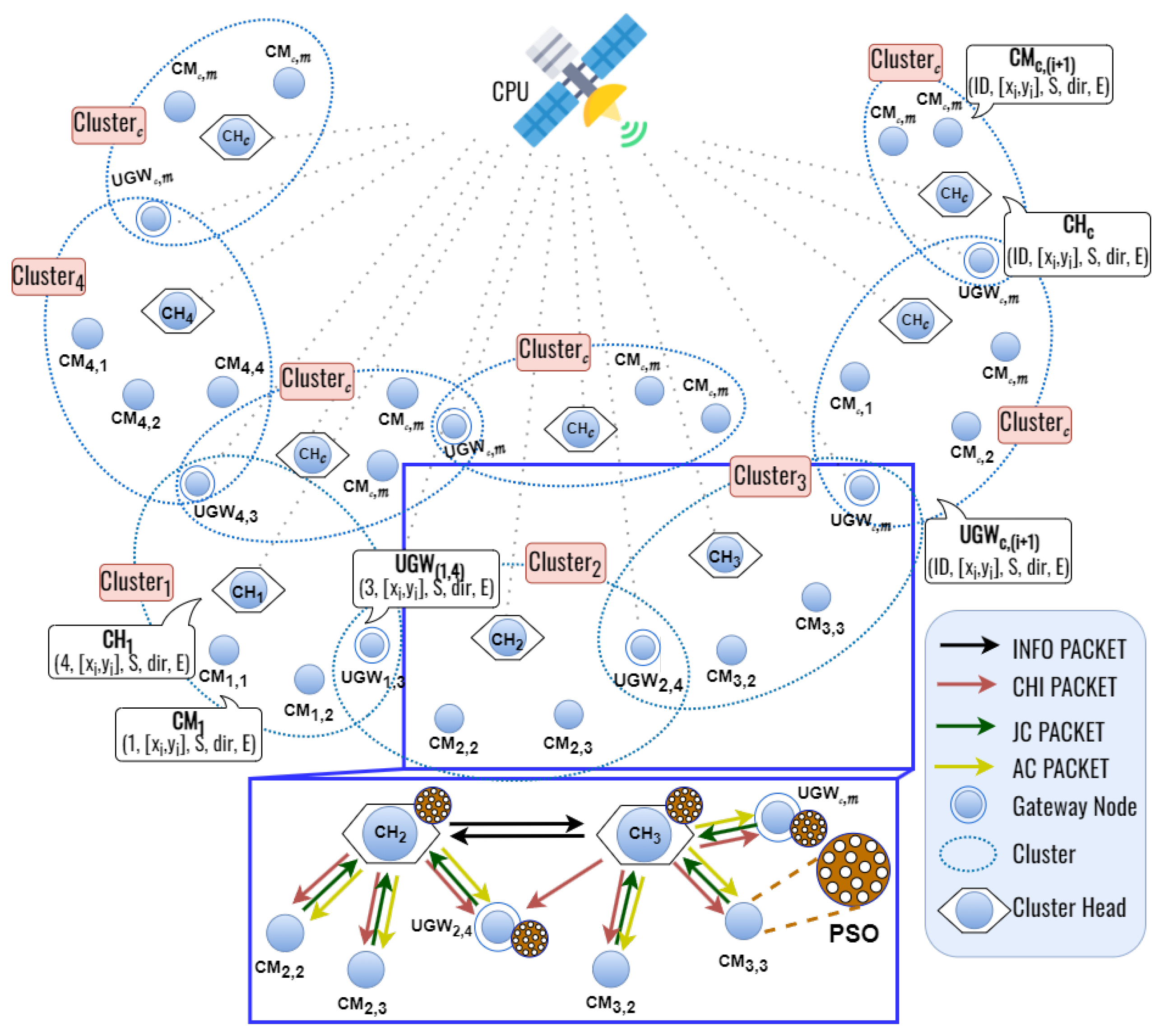
- We design a novel top-down particle swarm optimization (TD-PSO)-based clustering protocol in FANETs to reduce control overhead and improve route connectivity. The proposed TD-PSO, considering the node position, velocity, direction, and remaining energy, forms a cluster to optimize the cost function by combining the remaining energy weight, cosine similarity, cosine distance, and node degree. This strategic approach leads to electing cluster heads. Furthermore, to ensure communication continuity between cluster heads when the subsequent ones fall outside of the transmission range, our TD-PSO protocol also designates gateway nodes.
- The performance evaluations show that the proposed DLSMR with TD-PSO protocol can establish a more robust route against wormhole attacks than the benchmark protocol. Additionally, the proposed TD-PSO clustering supports stronger connectivity as clustering changes the network topology hierarchically. In addition to that, we also compare the proposed protocol under two different mobility models (reference point group mobility and random waypoint) to show the effectiveness of the proposed protocol.
2. Overview of Wormhole Attack
3. The Particle Swarm Optimization Theory
4. The Proposed Secure Multicast Routing Protocol: DLSMR
4.1. The Basic Concept of the Proposed Secure Multicast Routing and Clustering Protocol
- Step 1 (Clustering Process): Firstly, we consider the entire network as a single cluster, which is then recursively divided into smaller clusters based on the weight of the node degree, cosine similarity, cosine distance, and remaining energy. We identify flying nodes as potential cluster heads in this top-down clustering process as they inherently possess stronger capabilities within the cluster. Moreover, the flying node with the highest remaining energy is elected as the since it has to work harder than the member nodes as noted in [23]. A flying node that is not selected as a cluster head receives two or more cluster head information (CHI) packets from the , and then that node becomes an . Otherwise, the ground nodes can only serve as cluster members. To select the optimal cluster head, the cluster member candidates use the PSO algorithm to optimize costs. Unlike the traditional clustering method of [23], we introduce a TD-PSO protocol to improve control overhead during cluster formation.
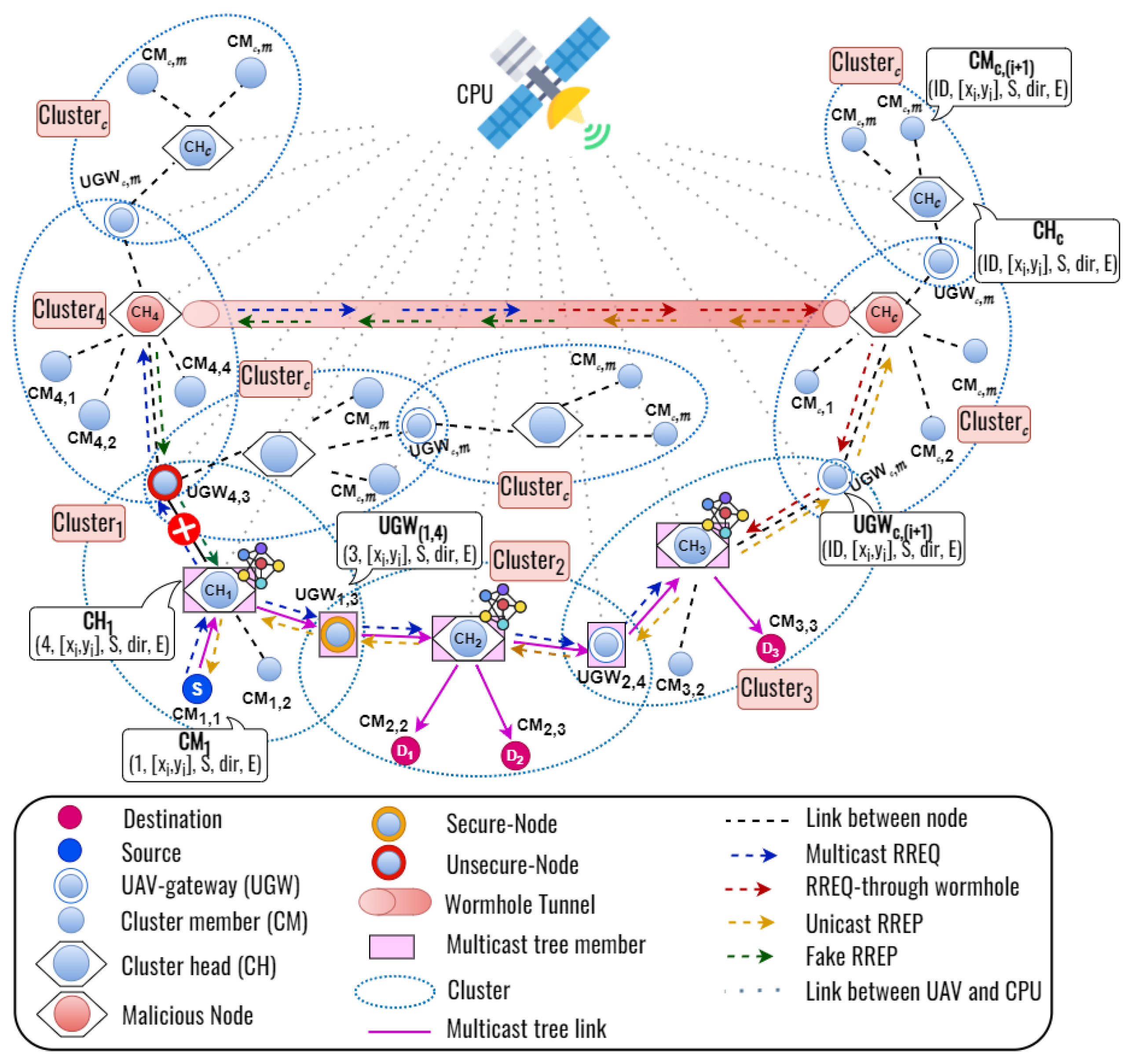
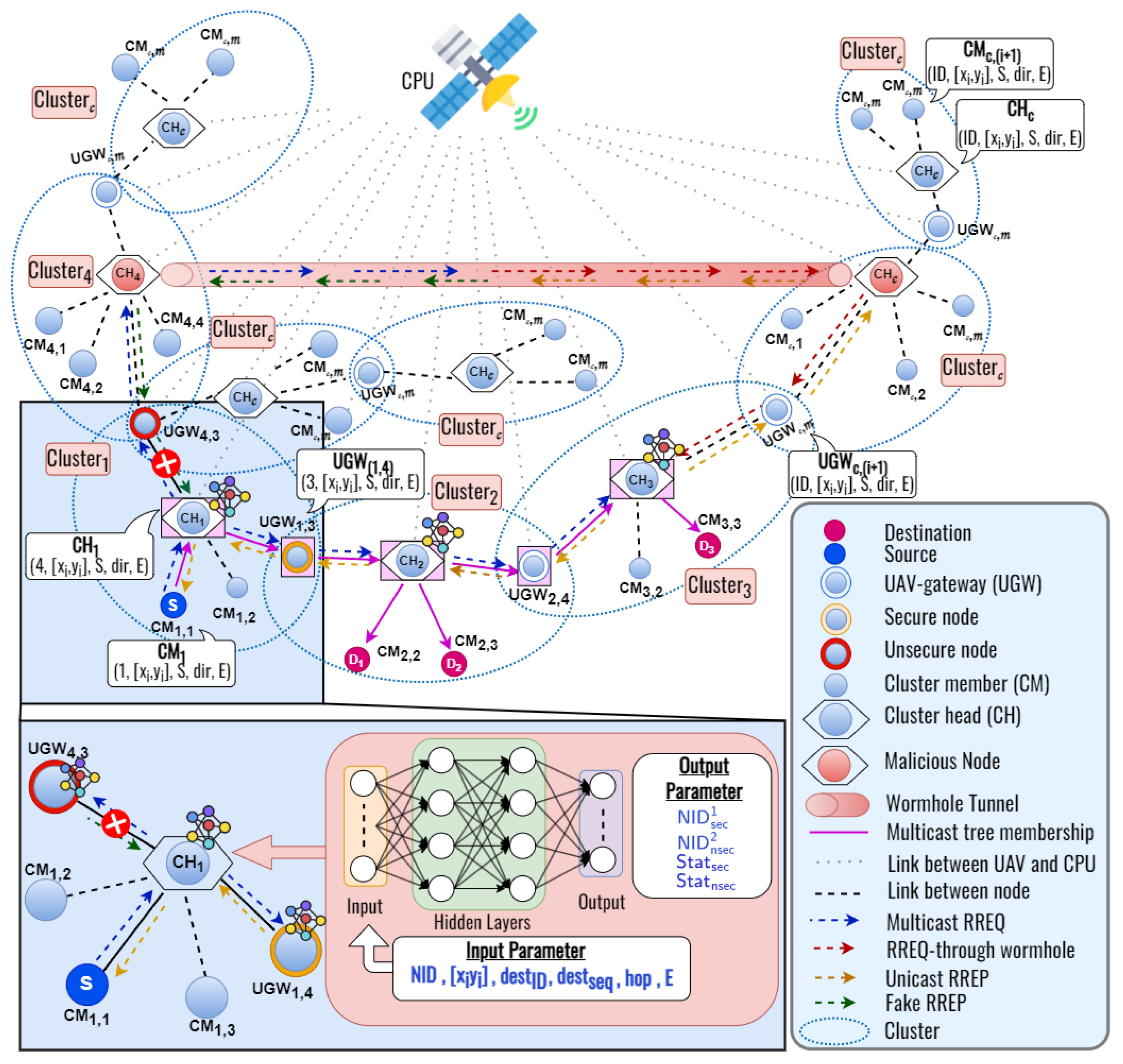
- Step 2 (Multicast Routing Process): Following the clustering process, each destination node that wants to receive data transmission sends a join request to the within the cluster. Then, a source node sends a to each cluster head by unicast to find the multiple destination nodes. After that, will broadcast the packet to each to find the multiple destination nodes. When the receives the packet, it updates its routing table and re-broadcasts the packet to the neighbor nodes. When a who has a multicast group ID receives an packet, they update the routing table and reply a packet to the previous node by unicast. In addition to that, the wormhole attacker also forwards the and packets. In this work, we develop a novel DL framework to predict the secure next node while establishing the route from a source to the multicast group destinations. Based on the DL framework, we can train a DNN model to learn wormhole nodes’ characteristics and distinguish them from legitimate ones. Each flying node in the network utilizes a deep learning framework to find the next secure nodes for multiple destinations. We consider the node ID, node’s position, destination ID, destination sequence, hop count, and the remaining energy of the node as the trainable input parameter, and the secure and unsecured node ID, secure and unsecured status as output parameters of the DNN model. When a node receives a packet, the contents of the relevant packet will be used in the DL framework. After training, the DNN model produces secure and unsecured node ID and their status as output. For example, as we can see in Figure 1, when the receives two packets which are from the neighbor nodes and the wormhole nodes, the proposed DLSMR protocol can establish a secure multicast route from and also with a multicast tree to avoid the wormhole attack.
4.2. The Proposed Clustering Protocol: Top-Down Particle Swarm Optimization (TD-PSO)
4.2.1. The Basic Concept of the TD-PSO
4.2.2. The Proposed Clustering Protocol: TD-PSO
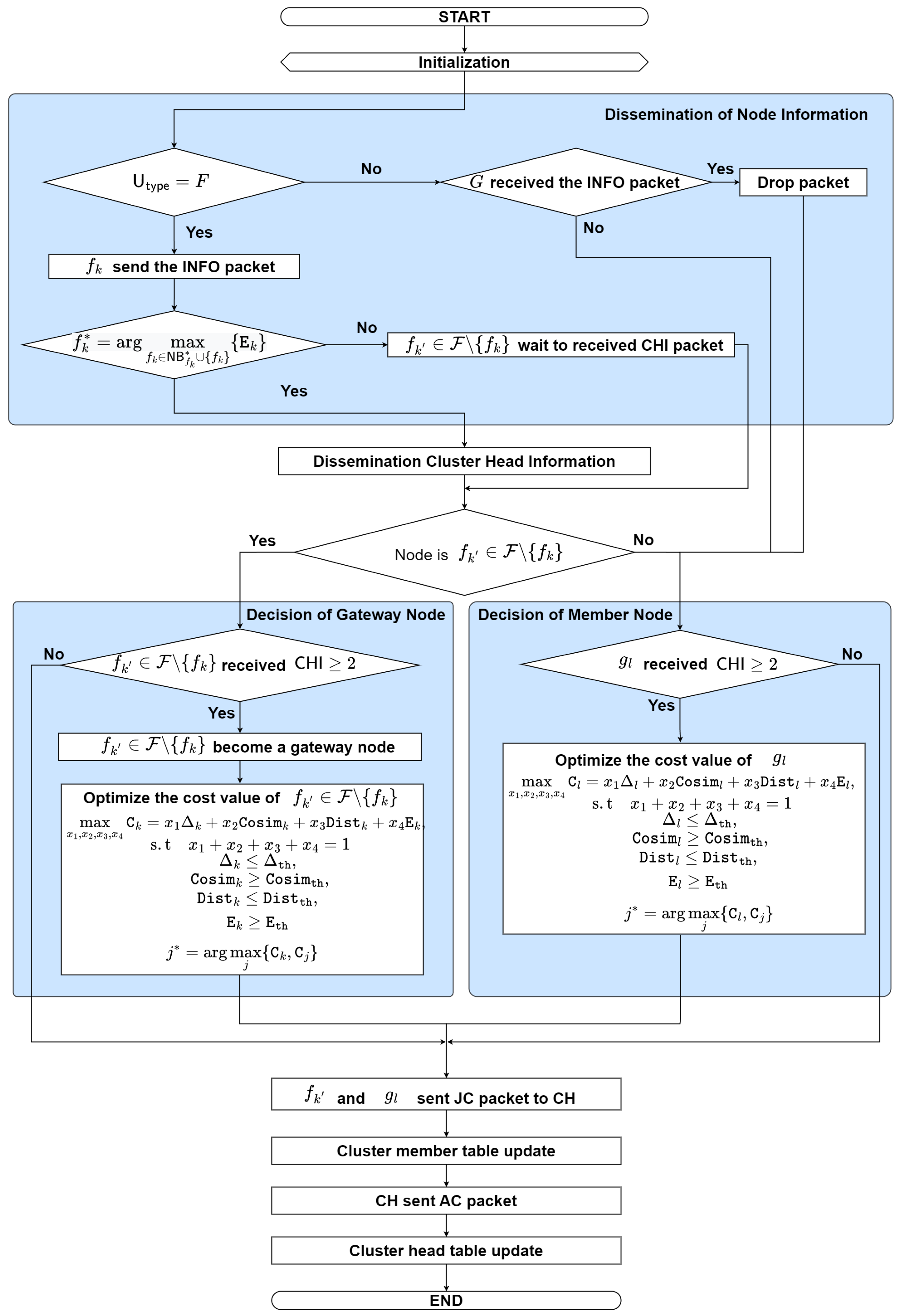
- Step 0: InitializationThe nodes turn on and operate independently when the simulation starts. Then, go to step 1.
- Step 1: Dissemination of Node InformationEach flying node periodically estimates its information such as speed, position, direction, and remaining energy. Then, generates and broadcasts information (INFO) packets to its neighbor UAV nodes. The INFO packet contains the following fields:where represents packet type, represents source node ID, represents destination node ID, represents the remaining energy of each node, and represents the type of node (0 is , 1 is ). Then, go to step 2.
- -
- If ground node receives an INFO packet, then it drops the packet; go to step 4. Otherwise, go to step 4.
- Step 2: Election of Cluster HeadIn order to support strong connectivity, the cluster head is selected by the most remaining energy among the candidate flying nodes, which mathematically can be expressed as
- -
- If = , the node becomes the cluster head; go to step 3.
- -
- Otherwise, wait to receive the CHI packet and go to step 4.
- Step 3: Dissemination of Cluster Head InformationThe node becomes the cluster head, then generates and broadcasts the CHI packet to be announced to its neighbor nodes. The CHI packet contains the following fields:where represents packet type, represents the source node ID, represents the destination node ID, represents the node’s position, represents the direction of the node, represents the speed of the node, represents the remaining energy of the node, and represents the type of the node (0 is , 1 is ).
- -
- If receive two or more CHI packets, then go to step 5.
- -
- Otherwise, go to step 4.
- Step 4: Decision of Member NodeWhen ground node receives two or more CHI packets, will decide which cluster head follows by calculating the cost function of the cluster head candidate. The ground node will select the cluster head candidate with the largest cost value. The objective is to maximize the cost value by considering weight value under node degree, cosine similarity, cosine distance, and energy, which can be formulated aswhere (4b) denotes that the total weight of the particle must be equal to one, (4c) denotes that the node degree difference must be lower than or equal to the node degree threshold, (4d) denotes that the cosine similarity between two nodes must be greater than or equal to the cosine similarity threshold, (4e) denotes that the cosine distance between nodes must be lower than or equal to the cosine distance threshold, and (4f) denotes that the energy of the cluster head must be greater than or equal to the energy threshold. We consider four factors which consist of the node degree difference, cosine similarity, the cosine distance between two nodes, and the remaining energy of its node. The node degree of its nodes can be written aswhere can be defined asstands for the node degree of the node , stands for the communication range of the node i, and stands for distance between node i and j. Then, the average node degree can be expressed asThe self-adaptive node degree variance is calculated by subtracting the node measure from its average measure, which can be expressed as:The second factor is cosine similarity between two nodes which can be defined as [29,37]where and are the i-th and j-th nodes’ vector information, respectively. Each node is related with a mobility vector information metric value (i.e., speed, direction, and position) , ,⋯,, where constitutes the vector values which indicate link information between nodes. Under a constrained communication distance, we can control the cluster member by considering the maximum cosine similarity. Afterwards, the third factor is the cosine distance of the node, which is used to find the distance between two nodes and can be formulated by [38]Thus, the selected cluster member can be mathematically formulated aswhere represents the cost of the node i and represents the the cost of the neighbor cluster heads near node j. After that, sends the join cluster (JC) packet to the . The JC packet contains the following fields:where represents packet type, represents source node ID, represents destination node ID, and represents the type of node. Then, go to step 5.
- -
- Otherwise, when only receives one CHI packet, then sends the JC packet to the and go to step 6.
- Step 5: Decision of Gateway NodeThe flying node receives two or more CHI packets and become a gateway node. Similar to the ground nodes, the flying node will decide which cluster head follows by calculating the cost function of the cluster head candidate. When the value of the cost function is larger, the relationship between the cluster head and node is better than other relationships which can be mathematically expressed aswhere (13b) denotes that the total weight of the particle must be equal to one, (13c) that denotes the node degree difference must be lower than or equal to the node degree threshold, (13d) denotes that the cosine similarity between two nodes must be greater than or equal to the cosine similarity threshold, (13e) denotes that the cosine distance between nodes must be lower than or equal to the cosine distance threshold, and (13f) denotes that the energy of the cluster head must be greater than or equal to the energy threshold. Thus, the selected cluster member can be mathematically formulated aswhere represents the cost of the node k and represents the cost of the neighbor cluster heads near node j. Then, sends the JC packet to the ; go to step 6.
- -
- Otherwise, when only receives one CHI packet, then it sends the JC packet to the ; go to step 6.
- Step 6: Cluster Member Table UpdatesWhen node and choose the , they update the cluster member () table as shown in Table 1 where is a unique identifier assigned to each node within the cluster, represents the identifier of the cluster head that the cluster member belongs to, and represents the type of user. Then, go to step 7.
- Step 7: Cluster Head Table UpdatesWhen receives a JC packet, replies with an accept packet (AC) to the transmitted node, and updates the cluster head table as shown in Table 2 where is a unique identifier assigned to each cluster head in the network, represents the identifier of the cluster member that belongs to the cluster managed by the cluster head, and represents the type of user. Finally, the cluster has been formed. The AC packet contains the following fields:where represent the packet type, source node ID, and destination node ID, respectively.
- -
- Otherwise, the AC packet will be dropped.
4.2.3. Top-Down Particle Swarm Optimization Model
| Algorithm 1 The TD-PSO algorithm to find global optimal points in problems (4) and (13) |
Output: Optimal solution and
|
4.3. The Proposed Deep Learning-Based Secure Multicast Routing Protocol: DLSMR
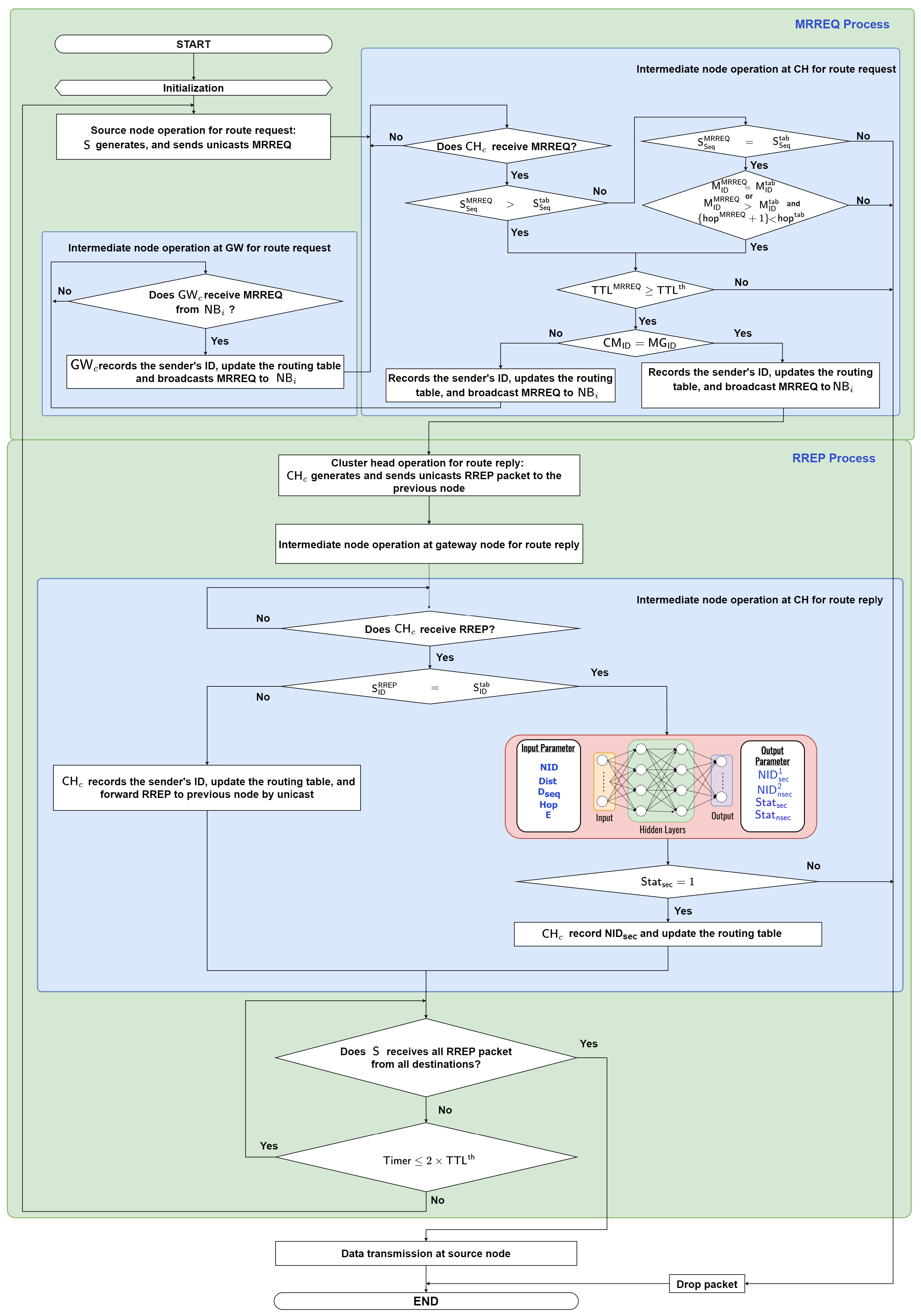
- Step 1: InitializationAfter the clustering process is completed, each destination node (multicast member node) in a cluster that wants to receive certain data sends a join request () to its cluster head by unicast. The contains the following:where denotes packet type, identifies the node that wants to join a multicast group, denotes the node ID that wishes to join, and denotes the status of the node (join, leave, etc.). Next, the cluster head stores the multicast ID () associated with this request in its own table; go to step 2.
- Step 2: Source Node Operation for Route Request: Generates and Sends Route Request PacketA node that wants to send data to the multicast group becomes the . initiates the process by generating a packet and unicasts this to its . The packet contains the following fields:where represents packet type, represents the source node ID, represents the multicast group ID, represents the multicast ID, is the source sequence number, denotes the number of hops between two nodes, and is the time to live of the packet in the network. Otherwise, go to step 3.
- Step 3: Intermediate Node Operation at Cluster Head for Route RequestWhen receives the packet, will first check the packet.
- ▪
- Step 3.1: If the at the received is larger than that of the routing table, then go to step 3.2.
- *
- Conversely, if the at the received equals the at the routing table and the at the received is equal to the at the routing table, or the is greater than the at the routing table and at the received is less than at the routing table, then go to step 3.2. Otherwise, the packet will be dropped.
- ▪
- Step 3.2: If the at the received is greater than or equal to the at the routing table, then go to step 3.3. Otherwise, the packet will be dropped.
- ▪
- Step 3.3: If the cluster member ID () is the same as the , records the sender’s ID, updates the routing table, and broadcasts to ; then, go to step 5.
- *
- Otherwise, records the sender’s ID and updates the routing table and broadcasts to the neighbor node () in its cluster or the next cluster heads; go to step 4.
- Step 4: Intermediate Node Operation at Gateway for Route RequestWhen the gateway node receives a packet from , records the sender’s ID and updates the routing table, then broadcasts the to their neighboring nodes until ; go to step 3.
- Step 5:Cluster head Operation for Route Reply: Generates and Sends Route Reply Packetgenerates and replies a packet to the previous node by unicast transmission. The packet contains the following fields:where represents the packet type, represents the source node ID, represents the destination ID, represents the multicast ID, is the destination sequence number which is the number of attempts to confirm control messages, represents the remaining energy of the node, represents the position of the node, and represents the number of hops to . Then, go to step 6.
- Step 6: Intermediate Node Operation at Gateway Node for Route ReplyThe intermediate node records the sender’s ID of packets and updates its routing table when it receives the packet. Then, forwards the packet to the previous node; go to step 7. Otherwise, waits until it receives the packet.
- Step 7: Intermediate Node Operation at CH for Route ReplyWhen the receives , then go to step 7.1. Otherwise, waits until it receives the packet.
- ▪
- Step 7.1: When the receives the , then checks the in the packet. The in the packet means the destination node ID. So, if the equals , then go to step step 7.2. Otherwise, records the sender’s ID, updates the routing table, and forwards to the previous node by unicast transmission; then, go to step 8.
- ▪
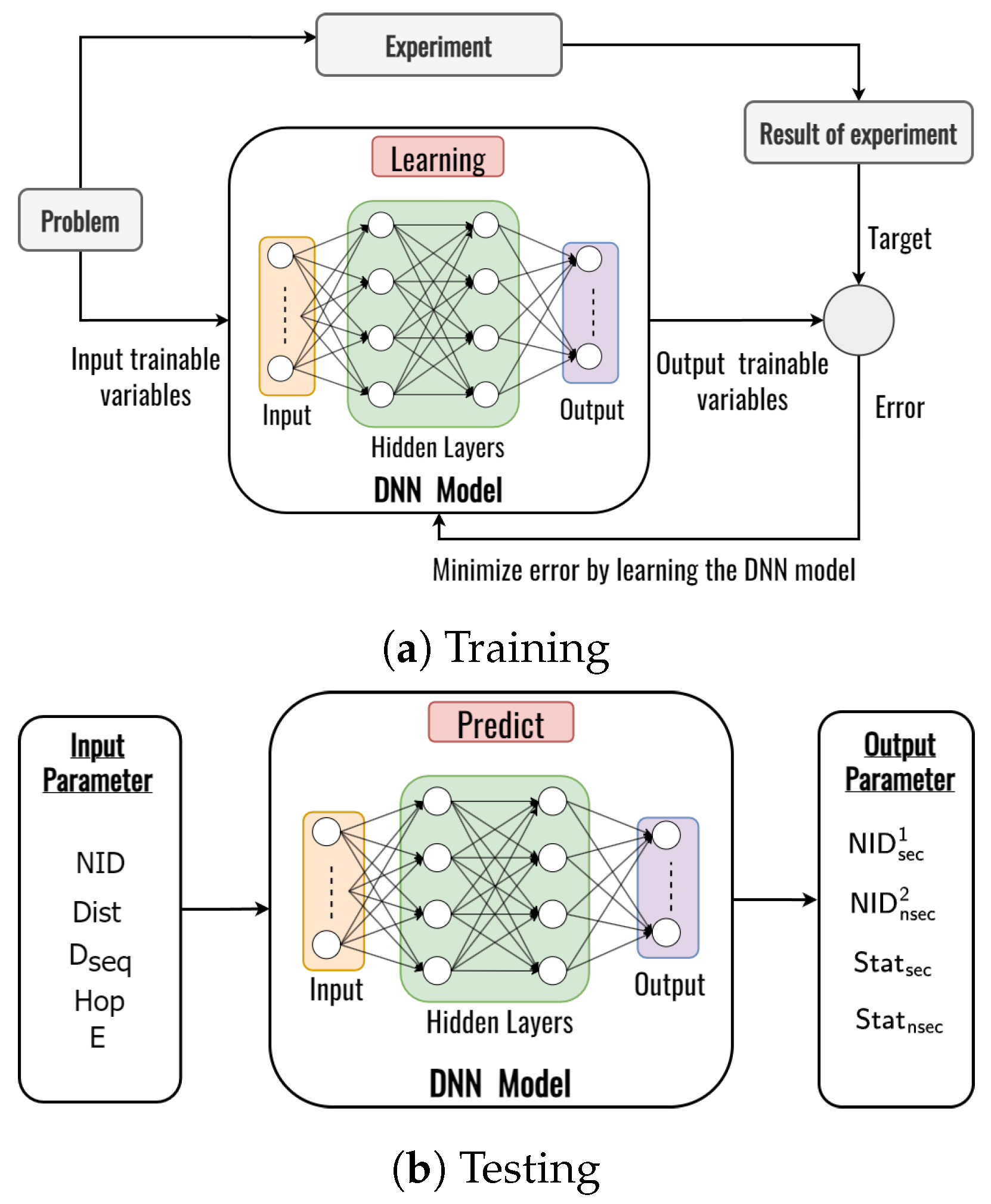
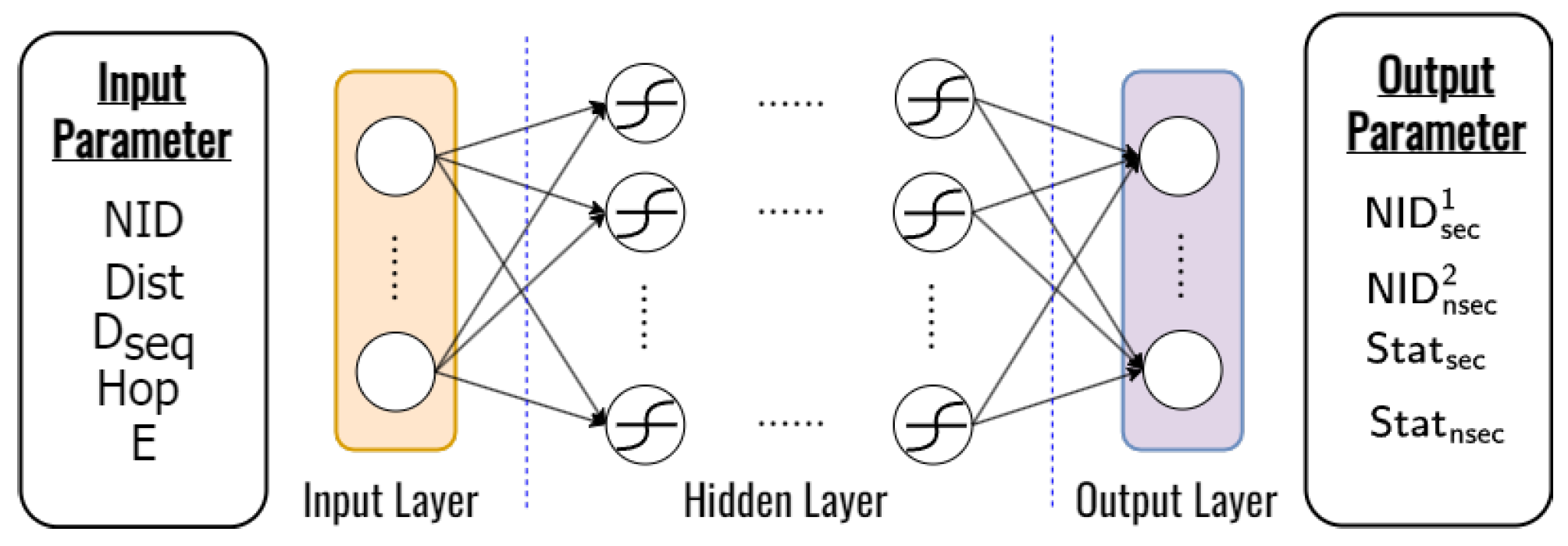
- Step 7.2: When the equals , we will predict the best secure next node with input parameter consisting of the node ID, position of the node, destination ID, destination sequence number, and remaining energy. The output parameters consists of the , , and the status of the node (secure or unsecured) to select the secure next node as the best next node while establishing the route from to multiple by using a DNN model; then, go to step step 7.3.
- ▪
- Step 7.3: If the equals 1, then can determine the secure route to be pursued by the secure next node. Then, records the , updates the routing table, and forwards to the previous node. The multicast tree routing table can be summarized in Table 4, where is the source ID, is the multicast group ID, is the source sequence number, is the destination sequence number , is the multicast node ID, is the previous node ID, is the next node ID, and represents the number of hops to . The routing table will be used to determine the next node to the multicast group that data packets will pass through during the data transmission process. Then, go to step 8. Otherwise, the packet will be dropped and the process is ended.
- Step 8: Source Node Operation for Route ReplyIf receives all packets from the multicast group, then go to the data transmission process in step 9. Otherwise, go to step Step 8.1:.
- ▪
- Step 8.1: If , wait for all packets from the multicast group until . Otherwise, go back to step 2.
- Step 9: Data Transmission at Source NodeWhen receives all packets from the multicast group , the multicasts the data packet to the next hops based on the deep learning framework. If a node of the tree receives a data packet, it will forward the data packet to the multicast group in the same way as the source.
4.4. The Proposed Deep Learning Design
5. Performance Evaluation
5.1. Simulation Environments and Parameters
5.2. Performance Metrics
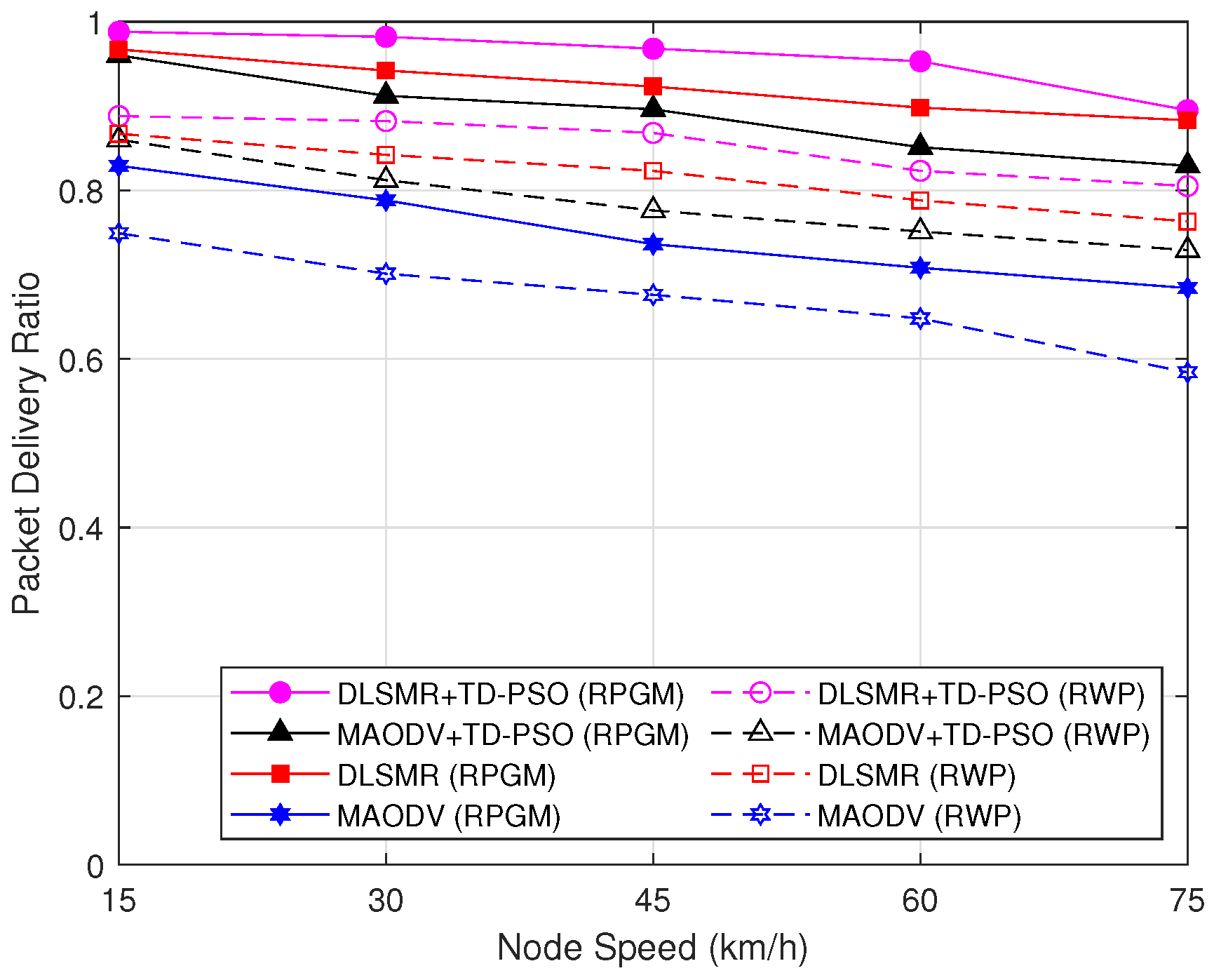
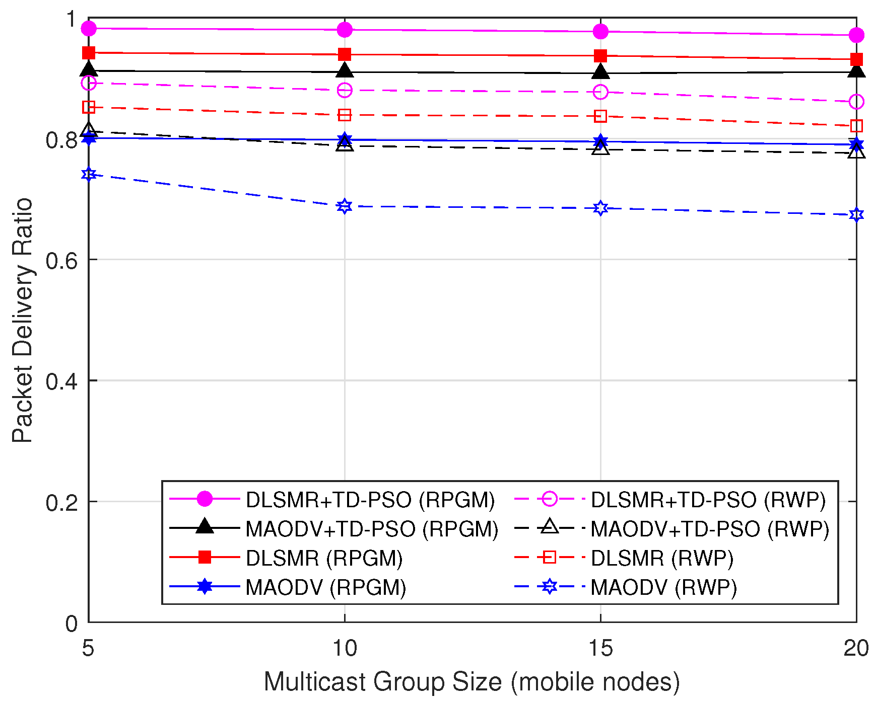
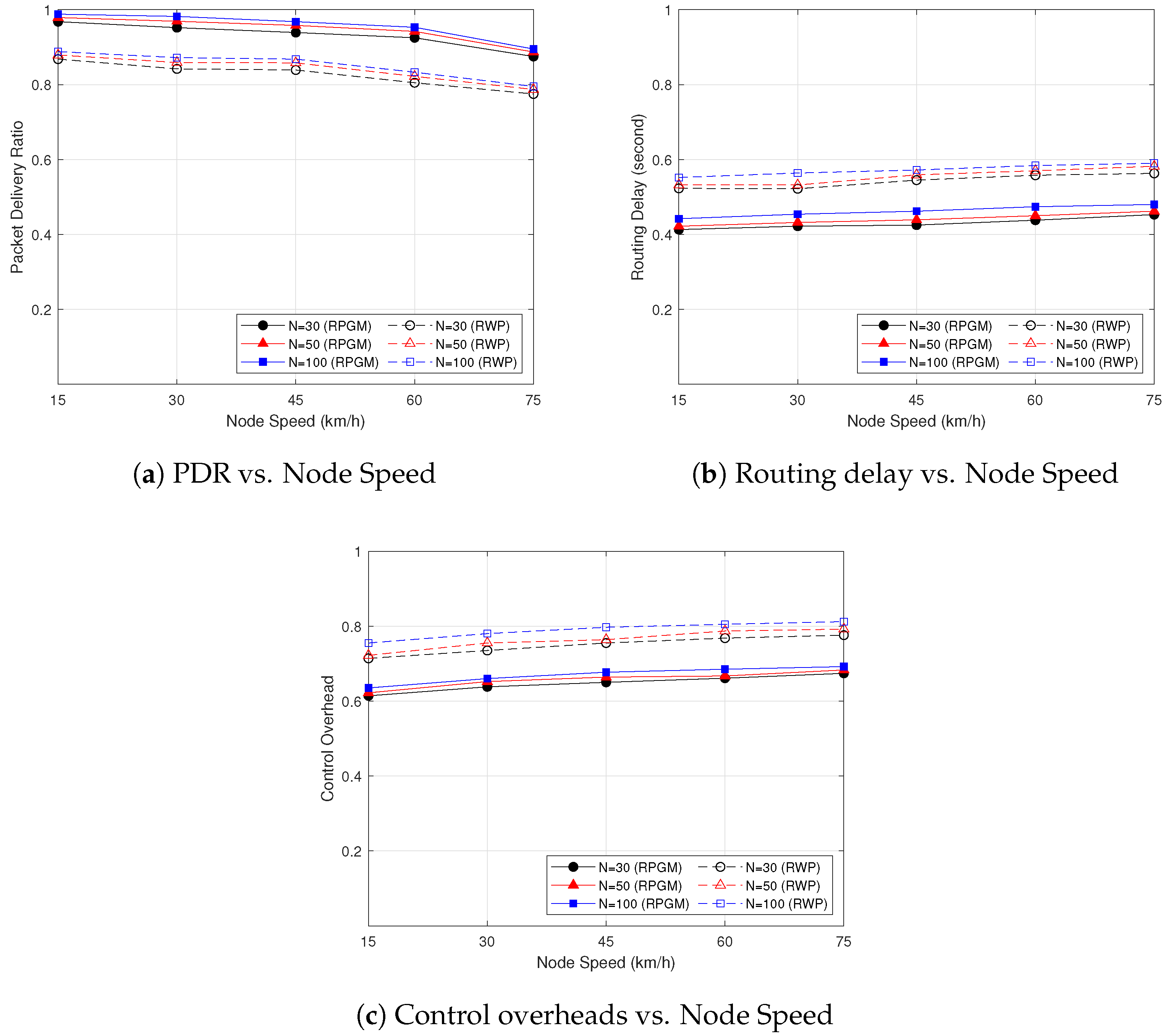
- Packet delivery ratio (PDR): This is defined as the number of data packets delivered to multicast destinations over the number of data packets supposed to be delivered to multicast destinations. This ratio represents the effectiveness of the routing strategy.
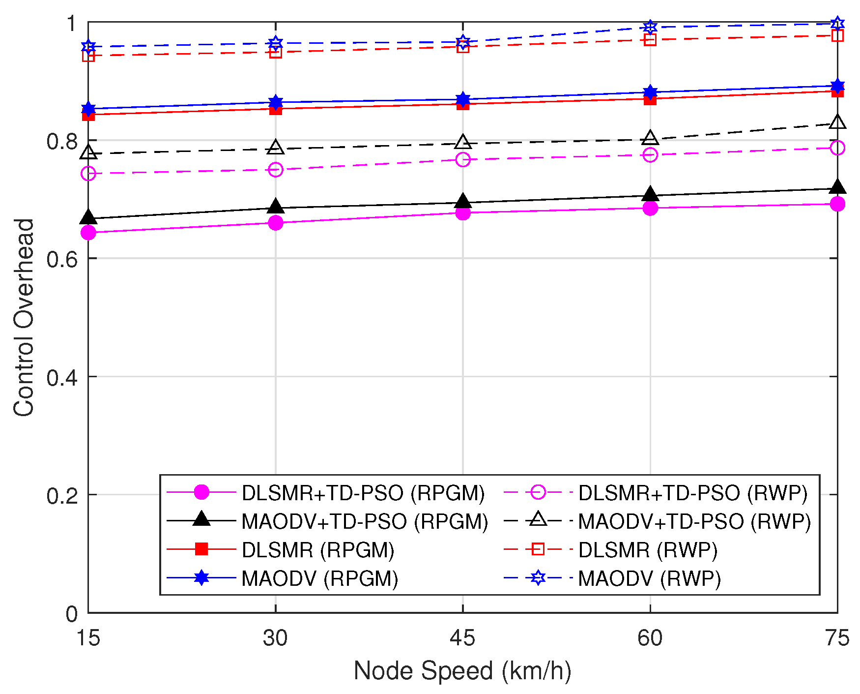
- Control overhead: This refers to the average number of control packets sent to nodes during the route creation process per session per node per multicast data delivered.
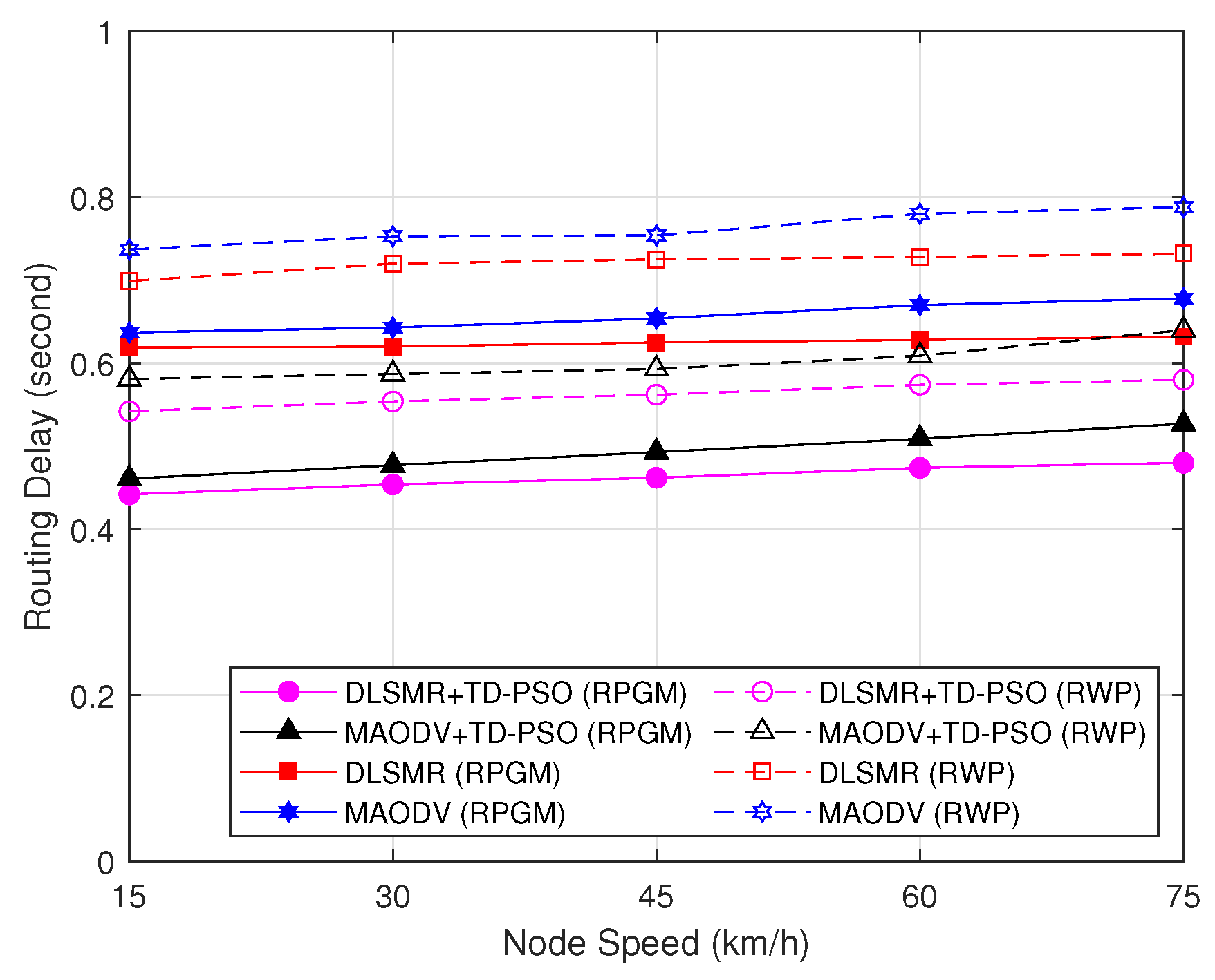
- Delay: This is defined as the average delay to establish a multicast route from source to multicast destinations per one session.
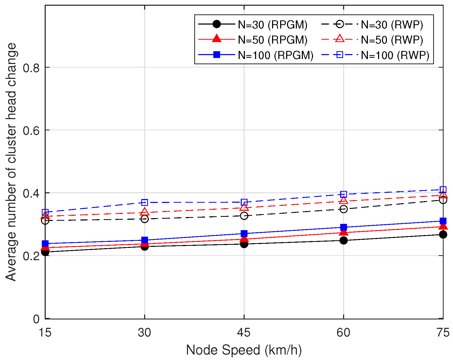
- The average number of cluster head changing: This refers to the number of cluster heads changing per cluster per session on average.
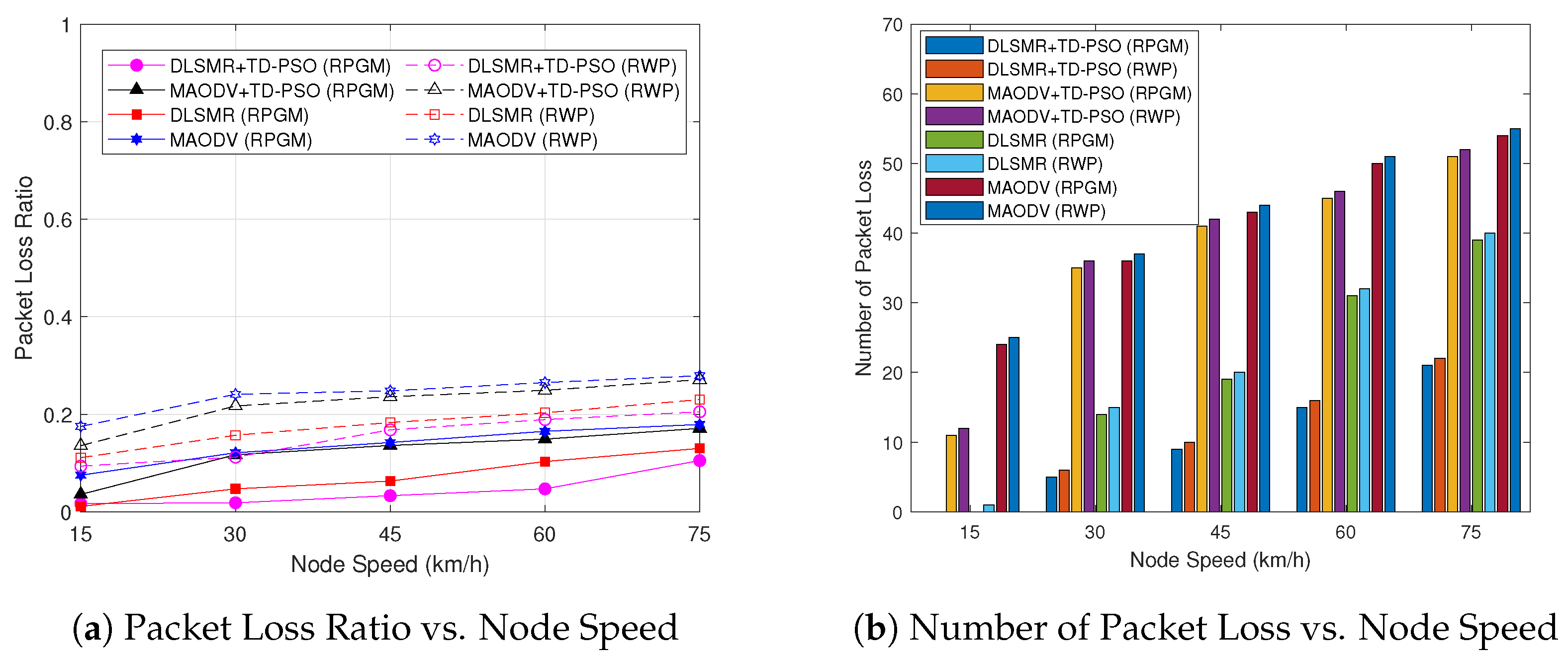
- Packet loss ratio: This is defined by the proportion of data packets that are lost during transmission from the sender in a multicast group. A lower packet loss ratio indicates better performance and reliability of the secure multicast routing protocol.
5.3. Numerical Results
6. Conclusions
Author Contributions
Funding
Institutional Review Board Statement
Informed Consent Statement
Data Availability Statement
Conflicts of Interest
Abbreviations
| AC | Accept cluster |
| CF-mMIMO | Cell-free massive MIMO |
| CH | Cluster head |
| CHI | Cluster head information |
| CM | Cluster member |
| DL | Deep learning |
| DLSMR | Deep learning secure multicast routing |
| DNN | Deep neural network |
| FANET | Flying ad hoc network |
| FN | Flying nodes |
| GN | Ground nodes |
| INFO | Information |
| JC | Join cluster |
| MAODV | Multicast ad hoc on-demand distance vector |
| MRREQ | Multicast route request |
| PDR | Packet delivery ratio |
| PSO | Particle swarm optimization |
| RREP | Route reply |
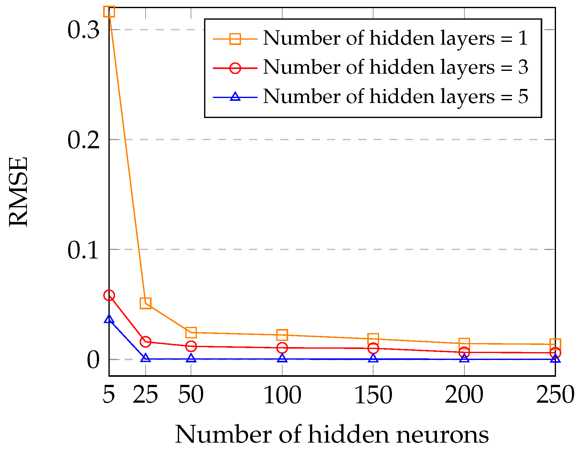
| RMSE | Root mean square error |
| RSSI | Received signal strength indicator |
| RWP | Random waypoint mobility |
| RPGM | Reference point group mobility |
| TD-PSO | Top-down particle swarm optimization |
| UAV | Unmanned aerial vehicle |
| UGW | UAV gateway node |
References
- Geraci, G.; Garcia-Rodriguez, A.; Giordano, L.G.; Lopez-Perez, D.; Bjoernson, E. Supporting UAV Cellular Communications through Massive MIMO. In Proceedings of the 2018 IEEE International Conference on Communications (ICC Workshops), Kansas City, MO, USA, 20–24 May 2018; pp. 1–6. [Google Scholar]
- Garcia-Rodriguez, A.; Geraci, G.; Lopez-Perez, D.; Giordano, L.G.; Ding, M.; Bjornson, E. The Essential Guide to Realizing 5G-Connected UAVs with Massive MIMO. IEEE Commun. Mag. 2019, 57, 84–90. [Google Scholar] [CrossRef]
- Shumeye Lakew, D.; Sa’ad, U.; Dao, N.N.; Na, W.; Cho, S. Routing in Flying Ad Hoc Networks: A Comprehensive Survey. IEEE Commun. Surv. Tutor. 2020, 22, 1071–1120. [Google Scholar] [CrossRef]
- Cho, J.; Sung, J.; Yoon, J.; Lee, H. Towards Persistent Surveillance and Reconnaissance Using a Connected Swarm of Multiple UAVs. IEEE Access 2020, 8, 157906–157917. [Google Scholar] [CrossRef]
- Lin, M.; Chen, T.; Ren, B.; Chen, H.; Zhang, M.; Guo, D. CADer: A Deep Reinforcement Learning Approach for Designing the Communication Architecture of System of Systems. IEEE Trans. Intell. Veh. 2023, 8, 3405–3417. [Google Scholar] [CrossRef]
- Wu, Q.; Xu, J.; Zeng, Y.; Ng, D.W.K.; Al-Dhahir, N.; Schober, R.; Swindlehurst, A.L. A Comprehensive Overview on 5G-and-Beyond Networks with UAVs: From Communications to Sensing and Intelligence. IEEE J. Sel. Areas Commun. 2021, 39, 2912–2945. [Google Scholar] [CrossRef]
- Lee, R.K.; Kitts, C.A.; Neumann, M.A.; Mcdonald, R.T. Multiple UAV Adaptive Navigation for Three-Dimensional Scalar Fields. IEEE Access 2021, 9, 122626–122654. [Google Scholar] [CrossRef]
- Zhao, N.; Lu, W.; Sheng, M.; Chen, Y.; Tang, J.; Yu, F.R.; Wong, K.K. UAV-Assisted Emergency Networks in Disasters. IEEE Wirel. Commun. 2019, 26, 45–51. [Google Scholar] [CrossRef]
- Al-Emadi, S.; Al-Mohannadi, A. Towards Enhancement of Network Communication Architectures and Routing Protocols for FANETs: A Survey. In Proceedings of the 2020 3rd International Conference on Advanced Communication Technologies and Networking (CommNet), Marrakech, Morocco, 4–6 September 2020; pp. 1–10. [Google Scholar]
- Chriki, A.; Touati, H.; Snoussi, H.; Kamoun, F. FANET: Communication, mobility models and security issues. Comput. Netw. 2019, 163, 106877. [Google Scholar] [CrossRef]
- Yang, X.; Yu, T.; Chen, Z.; Yang, J.; Hu, J.; Wu, Y. An Improved Weighted and Location-Based Clustering Scheme for Flying Ad Hoc Networks. Sensors 2022, 22, 3236. [Google Scholar] [CrossRef]
- Arafat, M.Y.; Moh, S. Localization and Clustering Based on Swarm Intelligence in UAV Networks for Emergency Communications. IEEE Internet Things J. 2019, 6, 8958–8976. [Google Scholar] [CrossRef]
- Zhang, J.; Feng, X.; Liu, Z. A Grid-Based Clustering Algorithm via Load Analysis for Industrial Internet of Things. IEEE Access 2018, 6, 13117–13128. [Google Scholar] [CrossRef]
- Ashour, O.; St-Hilaire, M.; Kunz, T.; Wang, M. A Survey of Applying Reinforcement Learning Techniques to Multicast Routing. In Proceedings of the 2019 IEEE 10th IEEE Annual Ubiquitous Computing, Electronics & Mobile Communication Conference (UEMCON), New York, NY, USA, 10–12 October 2019; pp. 1145–1151. [Google Scholar]
- Yadav, A.; Tripathi, S. QMRPRNS: Design of QoS multicast routing protocol using reliable node selection scheme for MANETs. Peer-Netw. Appl. 2017, 10, 897–909. [Google Scholar] [CrossRef]
- Motamedi, M.; Yazdani, N. Detection of black hole attack in wireless sensor network using UAV. In Proceedings of the 2015 7th Conference on Information and Knowledge Technology (IKT), Urmia, Iran, 26–28 May 2015; pp. 1–5. [Google Scholar]
- Agron, D.J.S.; Ramli, M.R.; Lee, J.M.; Kim, D.S. Secure Ground Control Station-based Routing Protocol for UAV Networks. In Proceedings of the 2019 International Conference on Information and Communication Technology Convergence (ICTC), Jeju Island, Republic of Korea, 16–18 October 2019; pp. 794–798. [Google Scholar]
- Munawar, S.; Ali, Z.; Waqas, M.; Tu, S.; Hassan, S.A.; Abbas, G. Cooperative Computational Offloading in Mobile Edge Computing for Vehicles: A Model-Based DNN Approach. IEEE Trans. Veh. Technol. 2023, 72, 3376–3391. [Google Scholar] [CrossRef]
- Tran, T.N.; Nguyen, T.V.; Shim, K.; da Costa, D.B.; An, B. A Deep Reinforcement Learning-Based QoS Routing Protocol Exploiting Cross-Layer Design in Cognitive Radio Mobile Ad Hoc Networks. IEEE Trans. Veh. Technol. 2022, 71, 13165–13181. [Google Scholar] [CrossRef]
- Khan, A.; Aftab, F.; Zhang, Z. BICSF: Bio-Inspired Clustering Scheme for FANETs. IEEE Access 2019, 7, 31446–31456. [Google Scholar] [CrossRef]
- Khan, A.; Khan, S.; Shahzad, F.; Zhang, Z.; Abuassba, A. Intelligent Cluster Routing Scheme for Flying Ad Hoc Networks. Sci. China Inf. Sci. 2021, 64, 182305. [Google Scholar] [CrossRef]
- Arafat, M.Y.; Moh, S. Bio-Inspired Approaches for Energy-Efficient Localization and Clustering in UAV Networks for Monitoring Wildfires in Remote Areas. IEEE Access 2021, 9, 18649–18669. [Google Scholar] [CrossRef]
- Pramitarini, Y.; Hendra, R.; Perdana, Y.; Shim, K.; An, B. Exploiting TAS schemes to Enhance the PHY-security in Cooperative NOMA Networks : A Deep Learning Approach. In Proceedings of the 2023 International Conference on Artificial Intelligence in Information and Communication, Bali, Indonesia, 27–29 December 2023; pp. 199–204. [Google Scholar]
- Hussen, H.R.; Choi, S.C.; Park, J.H.; Kim, J. Predictive geographic multicast routing protocol in flying ad hoc networks. Int. J. Distrib. Sens. Netw. 2019, 15, 1550147719843879. [Google Scholar] [CrossRef]
- Sharma, V.; Kumar, R.; Kumar, N. DPTR: Distributed priority tree-based routing protocol for FANETs. Comput. Commun. 2018, 122, 129–151. [Google Scholar] [CrossRef]
- Cheriguene, Y.; Djellikh, S.; Bousbaa, F.Z.; Lagraa, N.; Lakas, A.; Kerrache, C.A.; Karim Tahari, A.E. SEMRP: An Energy-efficient Multicast Routing Protocol for UAV Swarms. In Proceedings of the 2020 IEEE/ACM 24th International Symposium on Distributed Simulation and Real Time Applications (DS-RT), Prague, Czech Republic, 14–16 September 2020; pp. 1–8. [Google Scholar]
- Luo, X.; Chen, Y.; Li, M.; Luo, Q.; Xue, K.; Liu, S.; Chen, L. CREDND: A Novel Secure Neighbor Discovery Algorithm for Wormhole Attack. IEEE Access 2019, 7, 18194–18205. [Google Scholar] [CrossRef]
- Jamali, S.; Fotohi, R. DAWA: Defending against wormhole attack in MANETs by using fuzzy logic and artificial immune system. J. Supercomput. 2017, 73, 5173–5196. [Google Scholar] [CrossRef]
- Pramitarini, Y.; Perdana, R.H.Y.; Tran, T.N.; Shim, K.; An, B. A Hybrid Price Auction-Based Secure Routing Protocol Using Advanced Speed and Cosine Similarity-Based Clustering against Sinkhole Attack in VANETs. Sensors 2022, 22, 5811. [Google Scholar] [CrossRef]
- Liu, D.; Zhang, J.; Cui, J.; Ng, S.X.; Maunder, R.G.; Hanzo, L. Deep-Learning-Aided Packet Routing in Aeronautical Ad Hoc Networks Relying on Real Flight Data: From Single-Objective to Near-Pareto Multiobjective Optimization. IEEE Internet Things J. 2022, 9, 4598–4614. [Google Scholar] [CrossRef]
- Lu, J.; He, D.; Wang, Z. Secure Routing in Multihop Ad-Hoc Networks With SRR-Based Reinforcement Learning. IEEE Wirel. Commun. Lett. 2022, 11, 362–366. [Google Scholar] [CrossRef]
- Tahboush, M.; Agoyi, M. A Hybrid Wormhole Attack Detection in Mobile Ad-Hoc Network (MANET). IEEE Access 2021, 9, 11872–11883. [Google Scholar] [CrossRef]
- Bhosale, S.A.; Sonavane, S.S. Wormhole Attack Detection System for IoT Network: A Hybrid Approach. Wirel. Pers. Commun. 2022, 124, 1081–1108. [Google Scholar] [CrossRef]
- Kennedy, J.; Eberhart, R. Particle swarm optimization. In Proceedings of the Proc. ICNN’95—International Conference on Neural Networks, Perth, Australia, 27 November–1 December 1995; Volume 4, pp. 1942–1948. [Google Scholar]
- Zhang, Y.; Balochian, S.; Agarwal, P.; Bhatnagar, V.; Housheya, O.J. Artificial intelligence and its applications. Math. Probl. Eng. 2014, 840491. [Google Scholar] [CrossRef]
- Zhang, Y.; Shuihua, W.; Genlin, J. A Comprehensive Survey on Particle Swarm Optimization Algorithm and Its Applications. Math. Probl. Eng. 2015, 931256. [Google Scholar] [CrossRef]
- Nahar, A.; Sikarwar, H.; Das, D. CSBR: A Cosine Similarity Based Selective Broadcast Routing Protocol for Vehicular Ad-Hoc Networks. In Proceedings of the 2020 IFIP Networking Conference (Networking), Virtual, 20–25 June 2020; pp. 404–412. [Google Scholar]
- Abosamra, G.; Oqaibi, H. Using Residual Networks and Cosine Distance-Based K-NN Algorithm to Recognize On-Line Signatures. IEEE Access 2021, 9, 54962–54977. [Google Scholar] [CrossRef]
- Bhatia, T.K.; Tyagi, S.; Gusain, A.; Sharma, K. A Study on the Flying Ad-hoc Networks: Related Challenges, Routing Protocols and Mobility Models. In Proceedings of the 2022 11th International Conference on System Modeling & Advancement in Research Trends, SMART 2022, Moradabad, India, 16–17 December 2022; pp. 438–444. [Google Scholar]
- Papavassiliou, S.; An, B. Supporting multicasting in mobile ad hoc wireless networks: Issues, challenges, and current protocols. Wirel. Commun. Mob. Comput. 2002, 2, 115–130. [Google Scholar] [CrossRef]
- Halder, T.; Das, A.K.; Banerjee, S.; Sarkar, S.; Basak, A.; Ray, A.M.; Chakravarty, D. A Hybrid Localization Approach for UAV based on AODV and RSSI in FANETs. In Proceedings of the IGARSS 2022—2022 IEEE International Geoscience and Remote Sensing Symposium (IGARSS), Kuala Lumpur, Malaysia, 17–22 July 2022; pp. 7914–7917. [Google Scholar]
- Pramitarini, Y.; Perdana, R.H.Y.; Shim, K.; An, B. Particle Swarm Optimization-based Clustering Algorithm to Support QoS Routing Protocol in Flying Ad-hoc Networks with CF-mMIMO. In Proceedings of the 11th International Conference on Human Interaction and Emerging Technologies, Bangkok, Thailand, 31 January–2 February 2023; pp. 214–219. [Google Scholar]


| Packet Name | Full Name | Field Information |
|---|---|---|
| INFO | Information | |
| CHI | Cluster Head Information | |
| JC | Join Cluster | |
| AC | Accept Cluster |
| Packet Name | Full Name | Field Information |
|---|---|---|
| Join Request | ||
| Multicast Route Request | ||
| Route Reply |
| Size | Activation Function | |
|---|---|---|
| Input | 5 | - |
| Layer 1 | 150 | ELU |
| Layer 2 | 100 | ELU |
| Layer 3 | 200 | ELU |
| Layer 4 | 150 | ELU |
| Layer 5 | 100 | ELU |
| Output | 4 | LINEAR |
| Parameters | Value |
|---|---|
| Simulator | NS-3 simulator |
| Simulation area | 1000 × 1000 |
| Packet size | 1024 bits |
| Mobility model | RPGM and RWP |
| Transmission range | 250 m |
| Simulation time | 200 s |
| Session length | 5 s |
| Number of nodes | [30, 50, 100] |
| Wormhole pairs | 1 (Wormhole nodes 2) |
| Node’s speed range | [15:15:75] (km/h) |
| Receive signal strength indicator (RSSI) threshold | dBm |
| MAC protocol | 802.11a |
| Parameters | Value |
|---|---|
| Dataset | 1,000,000 |
| Epoch | 50 |
| Batch size | 256 |
| Optimizer | Adam |
| Initial learning rate | 0.00001 |
Disclaimer/Publisher’s Note: The statements, opinions and data contained in all publications are solely those of the individual author(s) and contributor(s) and not of MDPI and/or the editor(s). MDPI and/or the editor(s) disclaim responsibility for any injury to people or property resulting from any ideas, methods, instructions or products referred to in the content. |
© 2023 by the authors. Licensee MDPI, Basel, Switzerland. This article is an open access article distributed under the terms and conditions of the Creative Commons Attribution (CC BY) license (https://creativecommons.org/licenses/by/4.0/).
Share and Cite
Pramitarini, Y.; Perdana, R.H.Y.; Shim, K.; An, B. DLSMR: Deep Learning-Based Secure Multicast Routing Protocol against Wormhole Attack in Flying Ad Hoc Networks with Cell-Free Massive Multiple-Input Multiple-Output. Sensors 2023, 23, 7960. https://doi.org/10.3390/s23187960
Pramitarini Y, Perdana RHY, Shim K, An B. DLSMR: Deep Learning-Based Secure Multicast Routing Protocol against Wormhole Attack in Flying Ad Hoc Networks with Cell-Free Massive Multiple-Input Multiple-Output. Sensors. 2023; 23(18):7960. https://doi.org/10.3390/s23187960
Chicago/Turabian StylePramitarini, Yushintia, Ridho Hendra Yoga Perdana, Kyusung Shim, and Beongku An. 2023. "DLSMR: Deep Learning-Based Secure Multicast Routing Protocol against Wormhole Attack in Flying Ad Hoc Networks with Cell-Free Massive Multiple-Input Multiple-Output" Sensors 23, no. 18: 7960. https://doi.org/10.3390/s23187960