Article

Numerical Investigation on the Effect of Section Width on the Performance of Air Ejector with Rectangular Section

1
Marine Engineering College, Dalian Maritime University, Dalian 116026, China
2
College of Ocean Engineering, Guangdong Ocean University, Zhanjiang 524088, China
*
Author to whom correspondence should be addressed.
Entropy 2023, 25(1), 179; https://doi.org/10.3390/e25010179
Submission received: 20 December 2022 / Revised: 9 January 2023 / Accepted: 13 January 2023 / Published: 16 January 2023
(This article belongs to the Special Issue Entropy and Exergy Analysis in Ejector-Based Systems)

Abstract

:
Due to its simple structure and lack of moving parts, the supersonic air ejector has been widely applied in the fields of machinery, aerospace, and energy-saving. The performance of the ejector is influenced by the flow channel structure and the velocity of the jet, thus the confined jet is an important limiting factor for the performance of the supersonic air ejector. In order to investigate the effect of the confined jet on the performance of the ejector, an air ejector with a rectangular section was designed. The effects of the section width (Wc) on the entrainment ratio, velocity distribution, turbulent kinetic energy distribution, Mach number distribution, and vorticity distribution of the rectangular section air ejector were studied numerically. The numerical results indicated that the entrainment ratio of the rectangular section air ejector increased from 0.34 to 0.65 and the increment of the ER was 91.2% when the section width increased from 1 mm to 10 mm. As Wc increased, the region of the turbulent kinetic energy gradually expanded. The energy exchange between the primary fluid and the secondary fluid was mainly in the form of turbulent diffusion in the mixing chamber. In addition to Wc limiting the fluid flow in the rectangular section air ejector, the structure size of the rectangular section air ejector in the XOY plane also had a limiting effect on the internal fluid flow. In the rectangular section air ejector, the streamwise vortices played an important role in the mixing process. The increase of Wc would increase the distribution of the streamwise vortices in the constant-area section. Meanwhile, the distribution of the spanwise vortices would gradually decrease.

1. Introduction

An air ejector is a type of pneumatic device, which uses a vacuum created by the primary fluid to entrain the secondary fluid [1,2,3]. A low-speed secondary fluid interacts with the high-speed primary fluid in the mixing chamber to exchange mass, momentum, and energy in the restricted flow channel. Next, the mixing process of the two fluids generates complex gas dynamics phenomena such as shock waves and shear layer inside the air ejector [4,5,6]. The air ejector has a simple structure, no moving parts, and can work without consuming mechanical or electrical energy. The air ejector is an attractive and environmentally friendly device [7], which has been widely used in vacuum systems [8], wind tunnels [9], propulsion devices [10], high-altitude test facilities [11], gas-powered lasers [12], fuel cells [13], and spacesuit portable life support systems [14]. The air ejector has the simple structure, but its operating parameters [15] and structural parameters [16] have significant impacts on the performance of the air ejector. The selection of these parameters is the key to the design of the air ejector, which can directly affect the performance of the air ejector [17]. Mani et al. [18] found that the primary fluid pressure had a great effect on the entrainment ratio of the rectangular ejector through an investigation on the visualization of the shock wave inside the air ejector. Yang et al. [19] had conducted a comparative study on ejectors with circular, rectangular, elliptical, square, and cross-shaped nozzles. According to the results of the comparative study, vortexes with different degrees of reverse rotation appear at the tip of the nozzle outlet. The generation of the vortex will affect the mixing of two fluids in the restricted flow channel and increase the mechanical loss caused by the collision with the wall. Therefore, the vortex has an important influence on the characteristics of the internal flow inside the ejector and the performance of the ejector.
Additionally, the cross-section shape of the ejector and the limitation degree of the restricted flow channel have an important influence on the characteristics of the internal flow inside the ejector and the performance of the ejector. In order to further study the mixing process in the restricted flow channel of the ejector, Bouheraoua et al. [20] conducted a three-dimensional numerical simulation of the rectangular section air ejector. The results showed that in the initial stage of mixing the two fluids were laminar flow, while in the constant-area section they were transit to turbulent. During this process, the vortexes were formed and finally decomposed at the end of the constant-area section. Compared with the free jet, the restricted flow channel could promote the evolution of the confined jet flow field. Under the constraint of the restricted flow channel, the centerline velocity of the confined jet continuously decreased. Simultaneously, its entrainment performance fluctuated [21]. It should also be noted that the restricted flow channel had an important effect on the expansion process of the high-speed jet. The vortex generated at the nozzle corner could enhance the radial expansion of the high-speed jet [22]. The recirculation zone was affected by the structure of the restricted flow channel and the velocity of the jet. Compared with the velocity of the high-speed jet, the structure of the restricted flow channel played a dominant role in the generation of the recirculation zone [23], thus determining the central velocity and expansion of the high-speed jet.
In the restricted flow channel, the mixing process of the primary fluid and secondary fluid was complex [24]. Therefore, the confined jet was an important limiting factor affecting the performance of the ejector [25]. Compared with low-speed gas, supersonic gas had a better mixing effect; however, its potential gas dynamics are still being explored [26]. The double-choking phenomenon was one of the obstacles for studying the performance of the ejector. At present, the correctness of the Fabri-choking model has been confirmed by experimental and numerical investigation [27]. The internal flow of the ejector was often described by measurement of the wall pressure and the visualization experiment. The static pressure measurements of the wall could provide insight into the mixing process. The schlieren visualization experiment could capture the mixing characteristics of the confined jets [28]. However, current studies mainly focus on exploring the simulation method and experimental method of the internal flow inside the rectangular section air ejector, but neglects the changes in the flow characteristics of the air ejector.
To further study the flow state of the high-speed jet in the rectangular restricted flow channel, the three-dimensional numerical simulation of the rectangular section air ejector is carried out. In this paper the effects of section width (Wc) on entrainment ratio, velocity distribution, turbulent kinetic energy distribution, Mach number distribution, and vorticity distribution were studied.

2. Methods

2.1. Geometric Modeling

The methods of ejector design include constant area mixing [29], constant pressure mixing [30], constant rate of momentum change (CRMC) [31], and constant rate of kinetic energy change (CRKEC) [32]. The one-dimensional constant pressure mixing assumes that the constant pressure mixing occurs in the constant-area section of the ejector. It can obtain a more suitable air ejector performance. In order to obtain the structure parameters more suitable for the rectangular section air ejector, a one-dimensional constant pressure mixing theory was selected in this paper. According to the one-dimensional constant pressure mixing theory, the height of nozzle throat, height of nozzle inlet, height of nozzle outlet, and height of constant-area section for the rectangular section air ejector were designed. At the same time, the length dimension of the ejector could be obtained according to the empirical formula. The three-dimensional structure diagram of the rectangular section air ejector and the structure diagram of the rectangular section air ejector on the XOY plane are shown in Figure 1 and Figure 2, respectively. As shown in Figure 1, the rectangular section air ejector had two secondary fluid inlets. The mass flow rate of the secondary fluid was the sum of the mass flow rate of the upper secondary fluid inlet and the lower fluid inlet. Therefore, the entrainment ratio (ER) of the rectangular section air ejector was defined as follows:
E R = m e 1 + m e 2 m g
where mg was the mass flow rate of the primary fluid, me1 was the mass flow rate of the upper secondary fluid inlet, and me2 was the mass flow rate of the lower secondary fluid inlet.
As shown in Figure 2, the nozzle outlet (Xa), the inlet of the constant-area section (Xc0), the 1/4 of the constant-area section (Xc1/4), the 1/2 of the constant-area section (Xc1/2), the 3/4 of the constant-area section (Xc3/4), and the outlet of the constant-area section (Xc1) were selected as the analytical cross-section. The structure parameters of the rectangular section air ejector are shown in Table 1. When the Wc of the rectangular section air ejector was changed, the restricted degree of high-speed jet in the rectangular confined flow channel changed, thus affecting the ER of the rectangular section air ejector and the flow characteristics inside the ejector. In this paper, the ER of the rectangular section air ejector and the flow characteristics inside the ejector were investigated when the Wc of the rectangular section air ejector varied from 1 mm to 10 mm.

2.2. CFD Modeling

In order to simplify the simulation, several simplifications were made as follows:
(1)
The air in the rectangular section air ejector was the ideal compressible gas;
(2)
The wall was a non-slip adiabatic wall;
(3)
Ignore the temperature change caused by the supersonic flow of gas in the whole process;
(4)
The mixing process was the constant pressure mixing;
(5)
Ignore the initial velocity of the primary fluid inlet and the secondary fluid inlet.
The governing equation in the solving process was as follows:
Continuity equation:
ρ t + x i ρ u i = 0
Momentum equation:
t ρ u i + x i ρ u i u j = P x i + τ i j x j
Energy equation:
t ρ E + x i u i ρ E + P = α e f f T x i + u j τ i j e f f
with
τ i j = μ e f f u i x j + u j x i 2 3 μ e f f u k x k δ i j
ρ = P R T
where ρ was density, u was velocity, τ was viscous stress, μ was dynamic viscosity, E was total energy, P was static pressure, and δ was the Kronecker delta.
It had been verified by experiments that the k-ω SST model in the numerical simulation was more suitable to describe the performance of the ejector and the flow characteristics in the ejector when the primary fluid was air [33]. Therefore, the k-ω SST model was selected as the turbulence model in this paper.
k-ω SST turbulence model:
ρ u i u j ¯ = μ t u i x j + u j x i 2 3 ρ k + μ t u k x k δ i j
t ( ρ k ) = x j Γ k k x j + G k Y k
t ( ρ ω ) = x j Γ ω ω x j + G ω Y ω + D ω
where k was the turbulent kinetic energy, ω was the specific turbulence dissipation rate, Γ was the diffusion rate, G was the turbulent kinetic energy generated by the laminar flow velocity gradient, Y was the turbulent kinetic energy generated by diffusion, and D was the orthogonal divergence term.
Fluent 19.2 was used to solve the rectangular section air ejector model. The primary fluid inlet, the upper secondary fluid inlet, and the lower secondary fluid inlet were all set as “pressure inlet”, while the outlet of the diffuser chamber was set as “pressure outlet”. The other walls of the ejector were set as non-slip adiabatic walls. All temperatures were set at 293 K. The coupled method was selected for the iterative solution. The second-order was adopted for the discretization scheme for pressure. The second-order upwind discretization was applied for the all solution. All residual values of the calculated results were less than 10−6.

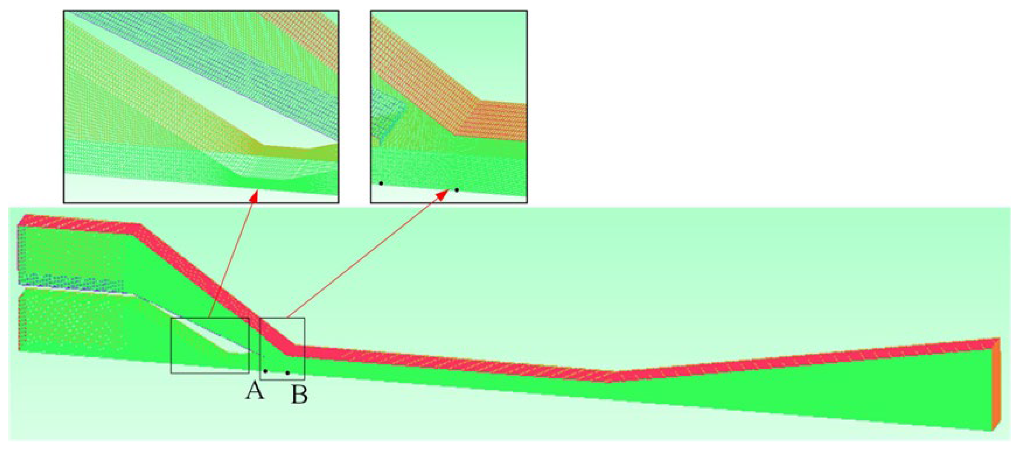
2.3. Validation of Grid Independence

In this paper, ICEM CFD was used to obtain the high-quality three-dimensional grid of the ejector. Since the structure of the rectangular section air ejector was symmetric along the XOZ profile, local axisymmetric meshes were selected to save calculation time. The structural mesh was adopted for meshing. In addition, the local mesh refinement approach was adopted in the region near the nozzle to improve the accuracy of the solution, as shown in Figure 3.
In order to ensure the accuracy of the solution and reduce the amount of computation, the grid independence of the rectangular section air ejector was verified. The number of grids increased from 148,864 to 842,258. The solutions were calculated for five different numbers of grids. Data detection points were set at the axis of the rectangular section air ejector for the validation of grid independence. The nozzle outlet (Point A) and the inlet of the constant-area section (Point B) were selected as the detection point. The velocity and pressure values of the two detection points were obtained from the calculation results. Further, the y+ of the first layer grid were kept at approximately 3 by encrypting the mesh of the wall and the nozzle, which satisfied the conditions for the k-ω SST model [34]. The grid independence validation results of Points A and B are shown in Table 2. In this paper, the rectangular section air ejectors under different Wc were calculated with no less than 279,910 grids, which could reduce the calculation time, while ensuring the accuracy of the calculation.

3. Results and Discussion

In the rectangular section air ejector, the mixed fluid will collide with the surrounding walls and cause a large amount of energy loss due to the limitation of Wc. In addition, Wc also affects the expansion state of the primary fluid. When Wc changes, the ER and the flow characteristic of the rectangular section air ejector change accordingly. This paper focuses on the effect of Wc on the performance and internal flow of the rectangular section air ejector when the primary fluid pressure (Pp) is 400 kPa, the secondary fluid pressure (Ps) is 100 kPa, and the XOY plane size is fixed.
When Wc increases from 1 mm to 10 mm, the variation of the ER of the rectangular section air ejector is shown in Figure 4. As shown in Figure 4, the ER of the rectangular section air ejector increases rapidly at first and then fluctuates slightly with the increase of Wc. When Wc is 2 mm, the increment of the ER of the rectangular section air ejector starts to decrease. When Wc is 5 mm, the incremental decrease of ER of the ejector with rectangular section is negligible, and the increment is only 0.014. When Wc is 9 mm, the ER of the rectangular section air ejector reaches a maximum. When Wc increases from 1 mm to 10 mm, the ER increases from 0.34 to 0.65, and the increment of the ER is 91.2%. This indicates that Wc has a great effect on the performance of the rectangular section air ejector. Therefore, in this paper the flow characteristics inside the rectangular section air ejector are studied from the aspects of velocity distribution, turbulent kinetic energy distribution, Mach number distribution, and vorticity distribution.

3.1. Velocity Distribution of Rectangular Section Air Ejector

The rectangular section air ejector does not have rotational symmetry. Therefore, the analysis method of the rectangular section air ejector is different from that of the conventional circular section air ejector. The XOY plane and the XOZ plane of the rectangular section air ejector were selected to analyze the velocity distribution, as shown in Figure 5 and Figure 6. As is shown in Figure 5, the length of the central jet from the nozzle gradually increases with the increase of Wc. When Wc reaches 5 mm, the length of the central jet reaches a maximum, and the flow of the central jet is in a stable state. As Wc continues to increase, flow separation occurs at the tail of the central jet. When Wc increases to 7 mm, the central jet will expand further and produce a droplet jet at the inlet of the diffuser. This is caused by the sudden change of the structure at the inlet of the diffuser, which causes the velocity of the central jet suddenly increasing at the end of the constant-area section. Furthermore, due to the restrictions of the wall, the central jet will have a violent collision with the wall in the process of flow when Wc is 1 mm. The friction between the central jet and the wall leads to the decrease of the central jet velocity, which is more obvious at the axis of the central jet. Figure 6 shows the velocity distribution of the rectangular section air ejector in the XOZ plane under different Wc. Due to the limitation of the wall structure, the central jet cannot expand freely and the velocity gradient of the central jet also changes. When Wc is 1 mm or 2 mm, the velocity of the central jet in the constant-area section is lower than that of other structures. With the increase of Wc, the velocity distribution area of the central jet expands gradually.

3.2. Turbulent Kinetic Energy Distribution of Rectangular Section Air Ejector

Figure 7 is the turbulent kinetic energy (TKE) distribution of the rectangular section air ejector in the XOY plane under different Wc. As demonstrated in Figure 7, with the increase of Wc, the region of the TKE gradually enlarges. In the mixing chamber, the energy exchange between the primary fluid and the secondary fluid is mainly in the form of turbulent diffusion. As Wc increases, more energy is exchanged. When Wc increases to 5 mm, the TKE in the constant-area section will no longer increase. The energy transfer process of the two fluids is stable. At this time, the energy exchange between the two fluids reaches a stable stage.
Figure 8 shows the TKE distribution of the rectangular section air ejector in the XOZ plane with different Wc. Figure 8 reveals that the TKE near the nozzle outlet fluctuates strongly when Wc is 1 mm. When Wc increases to 2 mm, the fluctuation region of the turbulent kinetic energy moves downstream, but the fluctuation of the TKE is still higher than that of other structures. Meanwhile, the mixing of the two fluids occurs closer to the inlet of the constant-area section. With the increase of Wc, the mixing area of the two fluids gradually expands and moves to the outlet of the constant-area section. When Wc increases to 5 mm, the fluctuation of the TKE occurs close to Xc1/2, and the fluctuation only occurs near the wall. As the Wc continues to increase, the primary fluid entrains the secondary fluid to the downstream of the constant-area section, where the mixing of the two fluids is gradually enhanced. At the same time, the fluctuation region of the TKE in the constant-area section will decrease until it disappears completely.
Figure 9 shows the TKE distribution of the rectangular section air ejector along the X axis under different Wc. Figure 9 indicates that the TKE gradually weakens with the development of the fluids in the ejector. With the increase of Wc, the region with the strongest turbulent kinetic energy gradually moves to Xc0, and the shape of the fluctuation region of the TKE gradually tends to be consistent. It should be noted that the wall constraint on the fluid flow in the rectangular air ejector will be weakened with the increase of Wc, but the dimension of the rectangular section air ejector in the XOY plane is fixed, which also plays a limiting role on the fluid flow in the rectangular section air ejector.

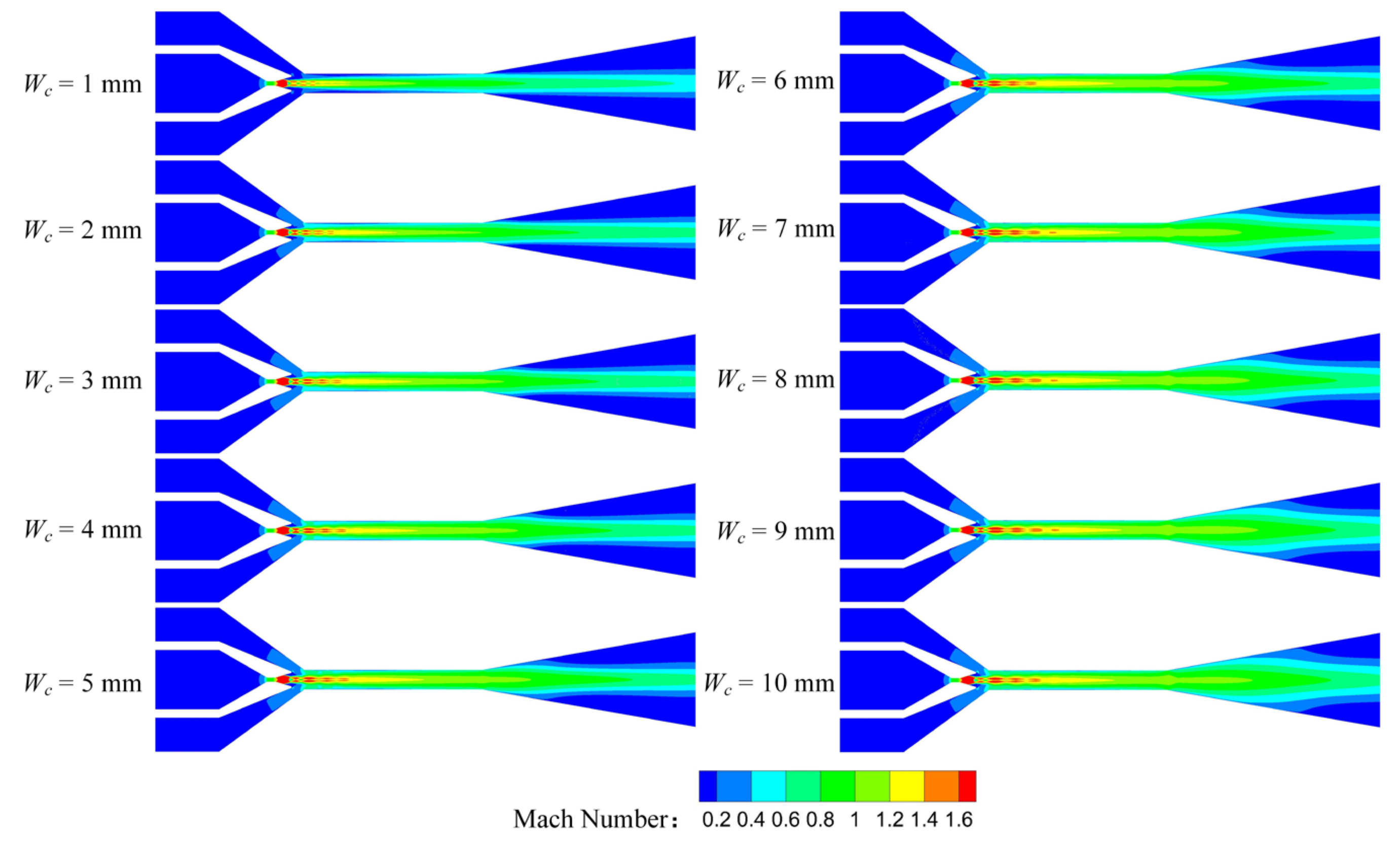
3.3. Mach Number Distribution of Rectangular Section Air Ejector

When the primary fluid leaves the nozzle, the central jet expands and accelerates into the mixing chamber. In the mixing chamber, the central jet forms a shock train alternating with expansion and compression. As far as we know, the structure of the shock wave, depending on the distribution of Mach number, has a direct effect on the performance of rectangular section air ejector. Therefore, the Mach number distribution of the rectangular section air ejectors under different Wc was studied in this paper.
Figure 10 shows the Mach number distribution of the rectangular section air ejector in the XOY plane under different Wc. As illustrated in Figure 10, the shock train length of the primary fluid is the shortest, due to the strongest limiting effect of the wall on the central jet when Wc is 1 mm. As Wc increases, the area of the central jet gradually increases, and the length of the shock train also gradually increases. When Wc increases to 5 mm, the length of the central jet reaches a maximum, but the length of the shock train continues to increase. When Wc is 9 mm, the length of the shock train reaches a maximum, and the ER of the air ejector also reaches its maximum. In addition, the shock train also forms a symmetric structure with the XOZ plane as the axis, which is called the double shock wave structure. This has not been observed in the conventional circular section air ejector. With the increase of Wc, the double shock wave structure gradually moves closer to the XOZ plane. As Wc increases to 7 mm, it begins to coincide at the front of the shock train. However, when Wc increases to 10 mm, the dual shock structure moves away from the XOZ plane. For further analysis, the Mach number distribution of the rectangular section air ejector in the XOZ plane under different Wc was obtained, as shown in Figure 11. As can be seen from Figure 11, there is no obvious shock train in the ejector when Wc is 1 mm. With the increase of Wc, the shock train gradually appears in the ejector, and the length of the shock train gradually becomes longer. This is caused by the gradual approach of the double shock wave structure to the XOZ plane. When Wc increases to 10 mm, the length of the shock train in the ejector becomes shorter again, indicating that the dual shock wave structure is further away from the XOZ plane.

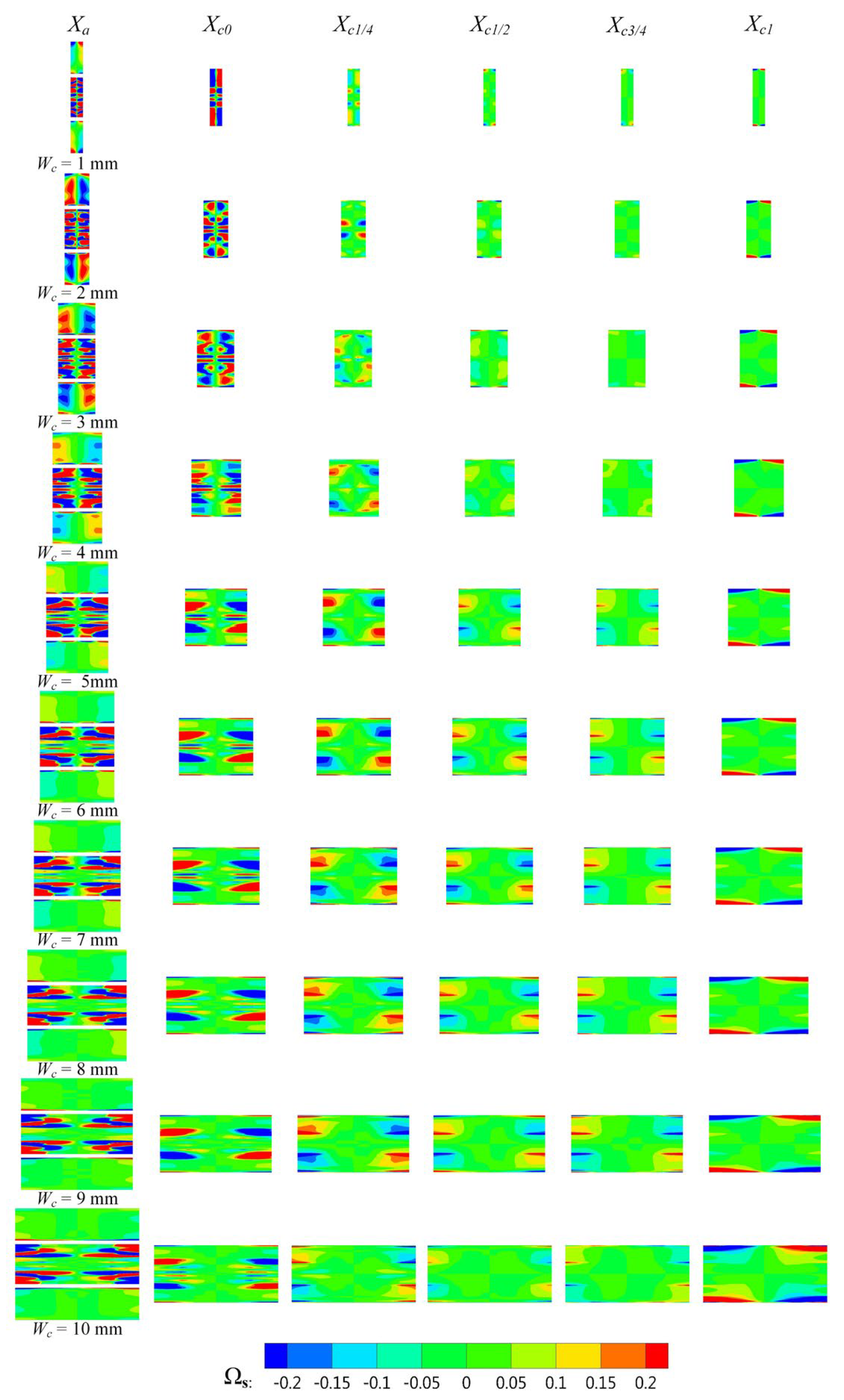
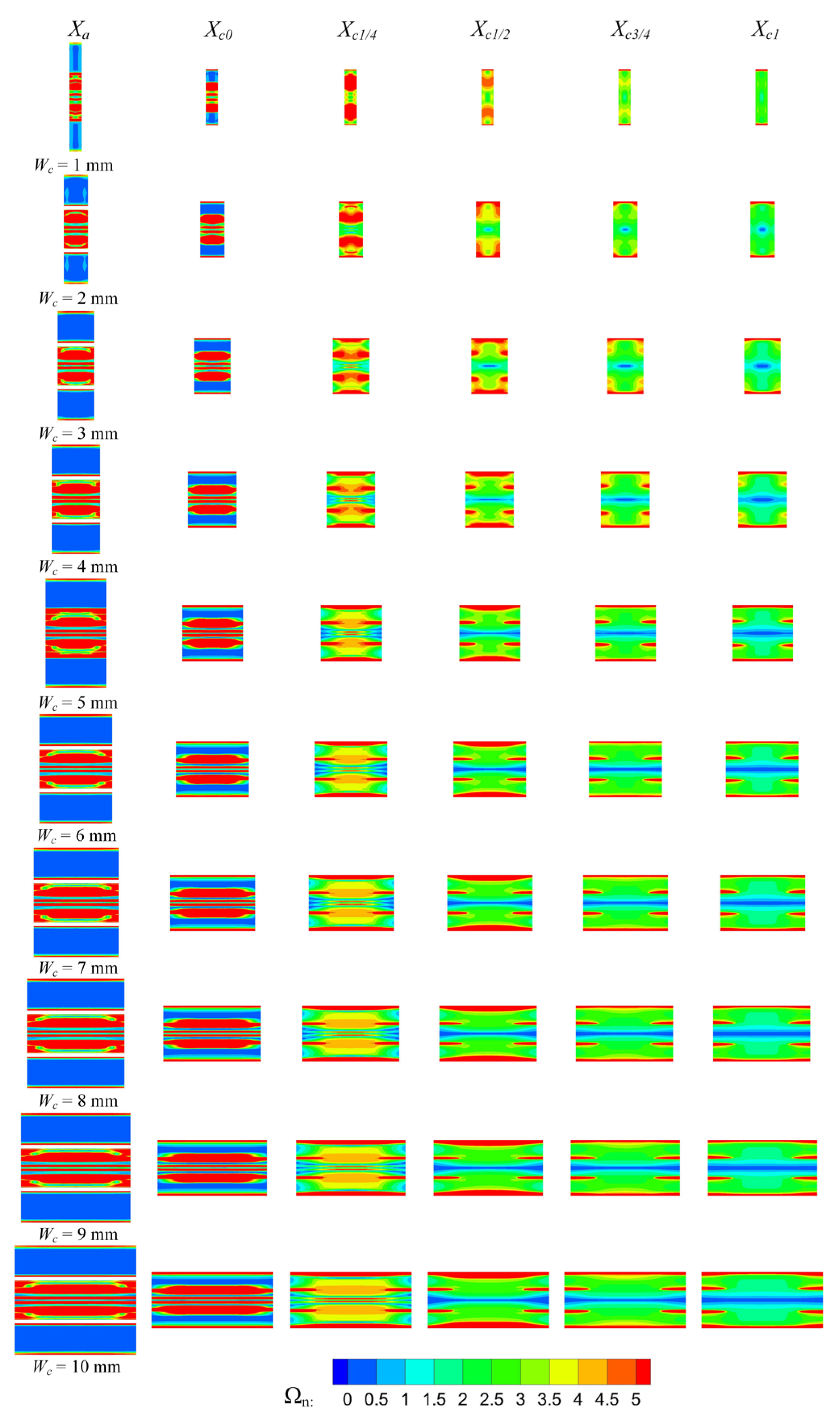
3.4. Vorticity Distribution of Rectangular Section Air Ejector

Vorticity is an important parameter to characterize the degree of turbulence. Under the restriction of Wc, the high-speed central jet impinges on the wall in the rectangular section air ejector. The vortex in the ejector gradually twists and stretches, expands to all directions in space, and forms a vorticity field. The vorticity field includes streamwise vortices and spanwise vortices. The streamwise vortices play an important role in the entrainment process between the primary fluid and the secondary fluid. The spanwise vortices are generated by the velocity gradient between the primary fluid and the secondary fluid, which is mainly distributed near the nozzle outlet. The streamwise vortices (Ωs) and the spanwise vortices (Ωn) are defined as follows [35]:
Ω s = D 0 U 0 ( w y v z )
Ω n = D 0 U 0 u z w x 2 + v x u y 2  
where D0 is the diameter of the nozzle outlet, and U0 is the mean velocity of the primary fluid the inlet of the nozzle.
The rotational motion of the streamwise vortices causes a relative flow between the primary fluid and the secondary fluid, which increases the mixing effect of the two fluids. Therefore, the influence of Wc on the streamwise vortices in the rectangular section air ejector was studied in this paper. Figure 12 shows the streamwise vortices distribution of the rectangular section air ejector along the X-axis under different Wc. In the figure, the red region is the positive vorticity, rotating in a counterclockwise direction. Meanwhile, the blue region is the negative vorticity, which rotates in a clockwise direction. In Figure 12, it can be seen how the motion of the streamwise vortices cause the secondary fluid to flow inward at the initial stage of the mixing process. With the development of fluid flow, the streamwise vortices at the center diffuse toward the wall, and the intensity of the streamwise vortices gradually weakens. Due to the sudden change of the structure of the rectangular section air ejector at the inlet of the diffuser, the intensity of the streamwise vortices increases sharply at the end of the constant-area section. When Wc is 1 mm, the streamwise vortices at Xc0 almost fill the entire section, and the wall attachment phenomenon of the streamwise vortices is the most obvious due to the limitation of rectangular flow channel. This wall attachment phenomenon is not conducive to the mixing of the two fluids, resulting in the lowest ER of the rectangular section air ejector under this structure. With the increase of Wc, the streamwise vortices at Xc0 begin to weaken. Simultaneously, the streamwise vortices develop gradually along the XOY plane, promoting the mixing of the two fluids.
Driven by viscous shear forces, the spanwise vortices are generated by the velocity gradient of the primary fluid and the secondary fluid along the edge of the geometric structure. The spanwise vortices are the vortex component perpendicular to the streamwise vortices. During the development of fluid flow, the spanwise vortices interact with the streamwise vortices. At the initial stage of the mixing process, the velocity gradient between the primary fluid and the secondary fluid is the largest, and the vortex structure near the nozzle is mainly the spanwise vortices. With the development of fluid flow, the spanwise vortices near the nozzle outlet begins to expand toward the wall and gradually weakens. Figure 13 is the spanwise vortices distribution of the rectangular section air ejector along the X-axis under different Wc. In Figure 13, it can be seen how the distribution of the spanwise vortices is most obviously constrained by the wall when Wc is 1 mm. With the increase of Wc, the spanwise vortices structure near the nozzle outlet began to expand towards the wall and gradually weakened. When Wc increases to 5 mm, the constraint of the wall on the spanwise vortices is weakened. As Wc continues to increase, the variation of the spanwise vortices in the constant-area section is no longer obvious.

4. Conclusions

In order to investigate the influence of Wc on the ER and the fluid flow characteristics of the rectangular section air ejector when the primary fluid pressure was 400 kPa and the secondary fluid pressure was 100 kPa, the velocity distribution, the turbulent kinetic energy distribution, the Mach number distribution, and the vorticity distribution in the rectangular section air ejector were studied by adopting the three-dimensional numerical simulation method. The following conclusions were obtained:
(1)
With the increase of Wc, the ER of the rectangular section air ejector first increases rapidly and then fluctuates slightly. When Wc increases from 1 mm to 10 mm, the minimum ER is 0.34, the maximum ER is 0.65, and the increment of the ER is 91.2%.
(2)
With the increase of Wc, the distribution of the TKE gradually expands. In the mixing chamber, the energy exchange between the primary fluid and the secondary fluid is mainly in the form of turbulent diffusion. When Wc increases to 5 mm, the TKE in the constant-area section no longer increases. Currently, the energy exchange between the two fluids reaches a stable stage. As Wc continues to increase, the primary fluid entrains the secondary fluid to the downstream of the constant-area section, and the mixing of the two fluids gradually increases in the downstream. In addition to Wc limiting the fluid flow in the rectangular section air ejector, the dimension of the rectangular section air ejector in the XOY plane also has a limiting effect on the fluid flow in the rectangular section air ejector.
(3)
With the increase of Wc, the region of the central jet gradually increases, as does the length of the shock train. When Wc increases to 5 mm, the length of the central jet reaches a maximum, but the length of the shock train continues to increase. When Wc is 9 mm, the length of the shock train reaches a maximum, and the ER of the rectangular section air ejector also reaches a maximum.
(4)
In the rectangular section air ejector, the streamwise vortices play a primary role in the mixing process. Due to the limitation of Wc, the mixing effect caused by the streamwise vortex is weakened, and the loss of the two fluids increases in the energy exchange process. Increasing Wc will increase the distribution of the streamwise vortices in the constant-area section, and simultaneously, the distribution of the spanwise vortices will gradually decrease.

Author Contributions

Conceptualization, investigation, writing and editing, project administration, funding acquisition: J.D.; validation, investigation, writing and editing: Y.Z.; methodology: S.S.; investigation: N.H. and M.L.; project administration, funding acquisition: X.P. All authors have read and agreed to the published version of the manuscript.

Funding

This research was funded by National Natural Science Foundation of China, grant number 51979022.

Institutional Review Board Statement

Not applicable.

Data Availability Statement

The research data supporting this publication are provided within this paper.

Conflicts of Interest

The authors declare no conflict of interest.

References

  1. Dutton, J.C.; Carroll, B.F. Optimal supersonic ejector designs. J. Fluids Eng. 1986, 108, 414–420. [Google Scholar] [CrossRef]
  2. Sriveerakul, T.; Aphornratana, S.; Chunnanond, K. Performance prediction of steam ejector using computational fluid dynamics: Part 2. Flow structure of a steam ejector influenced by operating pressures and geometries. Int. J. Therm. Sci. 2007, 46, 823–833. [Google Scholar] [CrossRef]
  3. Croquer, S.; Poncet, S.; Aidoun, Z. Thermodynamic Modelling of Supersonic Gas Ejector with Droplets. Entropy 2017, 19, 579. [Google Scholar] [CrossRef] [Green Version]
  4. Dadvar, M.; Afshari, E. Analysis of design parameters in anodic recirculation system based on ejector technology for PEM fuel cells: A new approach in designing. Int. J. Hydrog. Energy 2014, 39, 12061–12073. [Google Scholar] [CrossRef]
  5. Li, Y.Q.; Niu, C.; Shen, S.Q.; Mu, X. Turbulence Model Comparative Study for Complex Phenomena in Supersonic Steam Ejectors with Double Choking Mode. Entropy 2022, 24, 1215. [Google Scholar] [CrossRef]
  6. Yan, J.; Jiang, J.; Wang, Z. Optimization on Secondary Flow and Auxiliary Entrainment Inlets of an Ejector by Using Three-Dimensional Numerical Study. Entropy 2022, 24, 1241. [Google Scholar] [CrossRef]
  7. Kracik, J.; Dvorak, V. Secondary flow choking in axisymmetric supersonic air ejector with adjustable motive nozzle. Appl. Therm. Eng. 2022, 204, 117936. [Google Scholar] [CrossRef]
  8. Huang, X.Y.; Cheng, W.J.; Zhong, W.; Li, X. Development of new pressure regulator with flowrate-amplification using vacuum ejector. Vacuum 2017, 144, 172–182. [Google Scholar] [CrossRef]
  9. Kracik, J.; Dvorak, V.; Kolar, J. Development of air to air ejector for supersonic wind tunnel. EPJ Web Conf. 2014, 67, 02059. [Google Scholar] [CrossRef] [Green Version]
  10. Wilson, J.; Sgondea, A.; Paxson, D.E. Parametric investigation of thrust augmentation by ejectors on a pulsed detonation tube. J. Propul. Power 2007, 23, 108–115. [Google Scholar] [CrossRef]
  11. Kumaran, R.M.; Vivekanand, P.K.; Sundararajan, T. Optimization of Second Throat Ejectors for High-Altitude Test Facility. J. Propul. Power 2009, 25, 697–706. [Google Scholar] [CrossRef]
  12. Singhal, G.; Mainuddin; Tyagi, R.; Dawar, A.; Subbarao, P. Pressure recovery studies on a supersonic COIL with central ejector configuration. Opt. Laser Technol. 2010, 42, 1145–1153. [Google Scholar] [CrossRef]
  13. Rao, M.; Jagadeesh, G. Vector Evaluated Particle Swarm Optimization (VEPSO) of Supersonic Ejector for Hydrogen Fuel Cells. J. Fuel Cell Sci. Technol. 2010, 7, 041014. [Google Scholar]
  14. Guo, H.W.; Wang, C.; Wang, L. Optimization of the primary nozzle for design a high entrainment ejector in spacesuit portable life support system. Appl. Therm. Eng. 2022, 217, 119159. [Google Scholar] [CrossRef]
  15. Lin, C.; Cai, W.J.; Li, Y.Z.; Yan, J. Numerical investigation of geometry parameters for pressure recovery of an adjustable ejector in multi-evaporator refrigeration system. Appl. Therm. Eng. 2013, 61, 649–656. [Google Scholar] [CrossRef]
  16. Zhu, Y.H.; Cai, W.J.; Wen, C.Y. Numerical investigation of geometry parameters for design of high performance ejectors. Appl. Therm. Eng. 2009, 29, 898–905. [Google Scholar] [CrossRef]
  17. Sag, N.B.; Ersoy, H.K.; Hepbasli, A. Energetic and exergetic comparison of basic and ejector expander refrigeration systems operating under the same external conditions and cooling capacities. Energy Convers. Manag. 2015, 90, 184–194. [Google Scholar]
  18. Mani, A.K.; Tiwari, S.; Mani, A. Experimental studies on a rectangular ejector with air. Int. J. Therm. Sci. 2019, 140, 43–49. [Google Scholar]
  19. Yang, X.; Long, X.; Yao, X. Numerical investigation on the mixing process in a steam ejector with different nozzle structures. Int. J. Therm. Sci. 2012, 56, 95–106. [Google Scholar] [CrossRef]
  20. Bouheraoua, L.; Domingo, P.; Ribert, G. Large-eddy simulation of a supersonic lifted jet flame: Analysis of the turbulent flame base. Combust. Flame 2017, 179, 199–218. [Google Scholar] [CrossRef]
  21. Chua, L.P.; Lua, A.C. Measurements of a confined jet. Phys. Fluids 1998, 10, 3137–3144. [Google Scholar] [CrossRef]
  22. Ahmed, M.; Qin, N. Forebody shock control devices for drag and aero-heating reduction: A comprehensive survey with a practical perspective. Prog. Aerosp. Sci. 2020, 112, 100585. [Google Scholar] [CrossRef]
  23. Zhang, H.; Jia, L.; Cui, L.S.; Li, C. The Development of Top-Hat Flow Field in a Circular Symmetrical Subsonic Nozzle. J. Therm. Sci. 2019, 28, 975–983. [Google Scholar] [CrossRef]
  24. Karthick, S.K.; Rao, S.; Jagadeesh, G. Passive scalar mixing studies to identify the mixing length in a supersonic confined jet. Exp. Fluids 2017, 58, 59. [Google Scholar] [CrossRef]
  25. Chou, S.K.; Yang, P.R.; Yap, C. Maximum mass flow ratio due to secondary flow choking in an ejector refrigeration system. Int. J. Refrig. 2001, 24, 486–499. [Google Scholar] [CrossRef]
  26. Clemens, N.T.; Mungal, M.G. Large-scale structure and entrainment in the supersonic mixing layer. J. Fluid Mech. 1995, 284, 171–216. [Google Scholar] [CrossRef]
  27. Lamberts, O.; Chatelain, P.; Bartosiewicz, Y. Numerical and experimental evidence of the Fabri-choking in a supersonic ejector. Int. J. Heat Fluid Flow 2018, 69, 194–209. [Google Scholar] [CrossRef]
  28. Karthick, S.K.; Rao, S.; Jagadeesh, G.; Reddy, K.P.J. Parametric experimental studies on mixing characteristics within a low area ratio rectangular supersonic gaseous ejector. Phys. Fluids 2016, 28, 076101. [Google Scholar] [CrossRef]
  29. Yapici, R.; Ersoy, H.K. Performance characteristics of the ejector refrigeration system based on the constant area ejector flow model. Energy Convers. Manag. 2005, 46, 3117–3135. [Google Scholar] [CrossRef]
  30. Huang, B.J.; Chang, J.M.; Wang, C.P.; Petrenko, V.A. A 1-D analysis of ejector performance. Int. J. Refrig. 1999, 22, 354–364. [Google Scholar] [CrossRef]
  31. Kumar, V.; Singhal, G.; Subbarao, P. Study of supersonic flow in a constant rate of momentum change (CRMC) ejector with frictional effects. Appl. Therm. Eng. 2013, 60, 61–71. [Google Scholar] [CrossRef]
  32. Kumar, V.; Singhal, G.; Subbarao, P. Realization of novel constant rate of kinetic energy change (CRKEC) supersonic ejector. Energy 2018, 164, 694–706. [Google Scholar] [CrossRef]
  33. Mazzelli, F.; Little, A.B.; Garimella, S.; Bartosiewicz, Y. Computational and experimental analysis of supersonic air ejector: Turbulence modeling and assessment of 3D effects. Int. J. Heat Fluid Flow 2015, 56, 305–316. [Google Scholar] [CrossRef]
  34. Menter, F.R. Review of the shear-stress transport turbulence model experience from an industrial perspective. Int. J. Comput. Fluid Dyn. 2009, 23, 305–316. [Google Scholar] [CrossRef]
  35. Hu, H.; Saga, T.; Kobayashi, T.; Taniguchi, N. Mixing process in a lobed jet flow. AIAA J. 2002, 40, 1339–1345. [Google Scholar] [CrossRef]
Figure 1. Three-dimensional structure diagram of the rectangular section air ejector.
Entropy 25 00179 g001
Figure 2. Structure diagram of the rectangular section air ejector on the XOY plane.
Entropy 25 00179 g002
Figure 3. Three-dimensional grid diagram of the rectangular section air ejector.
Entropy 25 00179 g003
Figure 4. Variation of the ER of the rectangular section air ejector under different Wc.
Entropy 25 00179 g004
Figure 5. Variation of velocity distribution of the rectangular section air ejector in the XOY plane under different Wc.
Entropy 25 00179 g005
Figure 6. Variation of velocity distribution of the rectangular section air ejector in the XOZ plane under different Wc.
Entropy 25 00179 g006
Figure 7. Variation of turbulent kinetic energy distribution of the rectangular section air ejector in the XOY plane under different Wc.
Entropy 25 00179 g007
Figure 8. Variation of turbulent kinetic energy distribution of the rectangular section air ejector in the XOZ plane under different Wc.
Entropy 25 00179 g008
Figure 9. Variation of the turbulent kinetic energy distribution of the rectangular section air ejector along the X axis under different Wc.
Entropy 25 00179 g009
Figure 10. Variation of the Mach number distribution of the rectangular section air ejector in the XOY plane under different Wc.
Entropy 25 00179 g010
Figure 11. Variation of the Mach number distribution of the rectangular section air ejector in the XOZ plane under different Wc.
Entropy 25 00179 g011
Figure 12. Variation of the streamside vortex distribution of the rectangular section air ejector along the X axis under different Wc.
Entropy 25 00179 g012
Figure 13. Variation of the spanwise vortices distribution of the rectangular section air ejector along the X axis under different Wc.
Entropy 25 00179 g013
Table 1. Structure parameters of the rectangular section air ejector.
Parameter DescriptionSymbolValueUnits
Height of nozzle outletHa3.2mm
Height of constant-area sectionHc4.6mm
Height of nozzle inletHe14mm
Height of mixing chamber inletHm34mm
Height of diffuser outletHo22.3mm
Height of nozzle throatHt1mm
Length of constant-area sectionLc42mm
Length of nozzle throatLn2mm
Length of nozzle outlet to constant-area section inletLt3mm
Section widthWc1, 2, 3, 4, 5, 6, 7, 8, 9, 10mm
Divergent angle of nozzleθ032°
Convergent angle of mixing chamberθ172°
Divergent angle of diffusion chamberθ220°
Table 2. Grid independence test.
Grid NumbersVelocity (m/s)Deviation
(%)
Pressure (kPa)Deviation
(%)
Point A148,864582.97 22.17
213,634582.78−0.032622.230.27
279,910582.55−0.039522.310.36
503,690582.54−0.001722.310
842,258582.54022.310
Point B148,864422.57 100.09
213,634422.740.040299.76−0.33
279,910422.920.042699.56−0.20
503,690423.010.021399.10−0.46
842,258423.01099.100
Disclaimer/Publisher’s Note: The statements, opinions and data contained in all publications are solely those of the individual author(s) and contributor(s) and not of MDPI and/or the editor(s). MDPI and/or the editor(s) disclaim responsibility for any injury to people or property resulting from any ideas, methods, instructions or products referred to in the content.

