1. Introduction
The single-board computer Raspberry Pi is an ideal component for Internet of Things (IoT) applications due to its small size, low cost, availability, numerous interfaces, and processing power [
1]. Because of these advantages, Raspberry Pi is used in a wide variety of areas, such as robotics [
2,
3,
4], biology [
5], health care [
6,
7,
8,
9], security and surveillance [
10,
11,
12], and agricultural and environmental monitoring [
13,
14,
15].
To ensure that all interfaces of Raspberry Pi work properly, we have based our power supply design on the commercially available power supplies from the manufacturer, which provide a voltage of and are thus also within USB specifications. The presented module provides a solution for stable power supply without the need for specialized Raspberry Pi power adapters by providing an all-in-one solution to supply power from a variety of sources, such as 24 VDC, USB-PD, PoE, or 4S lithium polymer batteries. In addition, Internet of Things (IoT) applications can demand the integration of multiple sensors and/or actuators, as well as operating interfaces, alongside the processing unit. The module therefore provides power supply options for other system components to eliminate the need for additional power adaptors. This concept represents an innovative and adaptable approach for powering Raspberry Pi and IoT applications.
The module supports current Raspberry Pi models 3B+ and 4 and is already in use in the scope of the project Optocubes [
16]. The constraints imposed by the project’s intended use cases resulted in a compact, high-density solution, suitable to be fitted into a
mm
enclosure, including the Raspberry Pi system, as shown in [
17,
18].
2. Design
The power supply system for Raspberry Pi-based IoT applications provides a variety of interfaces for communication and power supply and two complementary circuit boards, OptosenseCore and OptosensePoE. OptosenseCore provides a steady that is achieved by converting power input levels, such as USB-PD and industrial standard 24 , or stabilizing the output of conventional USB power supplies by first boosting the voltage to 12 and subsequently providing a stable down-regulated , 3 Raspberry Pi power supply. The optional OptosensePoE-module offers power input of up to ≈ via a suitable PoE-input, thus allowing seamless integration into the most prevalent industrial power supply solution.
2.1. OptosenseCore
OptosenseCore’s key components are a battery management system (BMS), including cell monitoring; active cell balancing; temperature-, over- and under-voltage, and over-current protection; a battery charger; and different DC/DC converters that handle the power inputs and convert them to various voltages to supply the system. Another element is the central microcontroller unit, which controls the other components and handles communication with the Raspberry Pi. This connection is achieved via a pin header that matches the one already present on the Raspberry Pi by default. OptosenseCore provides a power button to turn the system on and off. Furthermore, OptosenseCore features a connector for a temperature sensor to allow temperature monitoring of, e.g., the battery. An E-Ink module can be connected to display relevant information using power-efficient technology. Due to cost–benefit and availability reasons, we chose the Waveshare 12563 2.9inch E-Ink display [
19]. Finally, OptosenseCore provides a voltage output that can be used to supply additional arbitrary peripherals with voltages in the range of 3–12 V with a maximum current output of 3
, assuming that the input source provides enough power. OptosenseCore’s voltage output is adjustable by using one of the microcontroller’s internal digital–analog converters (DAC) to manipulate the DC/DC converters’ feedback (see TPS54302 in
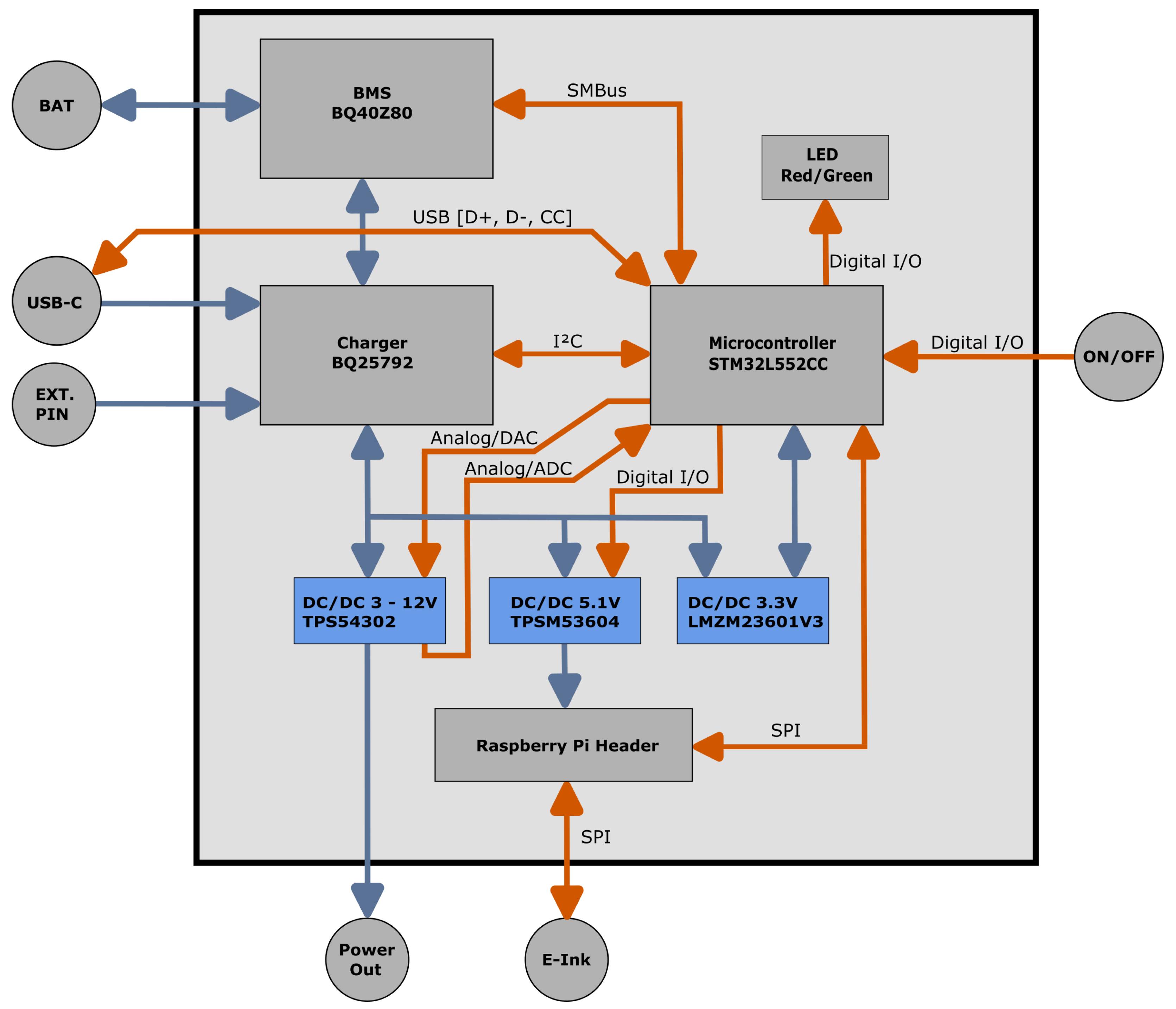
Figure 1).
Figure 1 shows a schematic representation of OptosenseCore and the interfaces and internal connections between the components mentioned above. Orange-colored pathways symbolize digital connections for communication, whereas blue-colored pathways symbolize power connections. The Raspberry Pi and the embedded microcontroller STM32L5 communicate using the SPI protocol. The microcontroller operates as a communication gateway to receive or pass on data on the BMS and the battery charger and, for this, uses the protocols I2C and SMBus (see
Figure 1). In addition, the STM32L5 communicates with USB-PD sources to receive their available profiles and selects an appropriate voltage. To encode the state of the system, the microcontroller operates a status LED with the following behavior, see
Table 1.
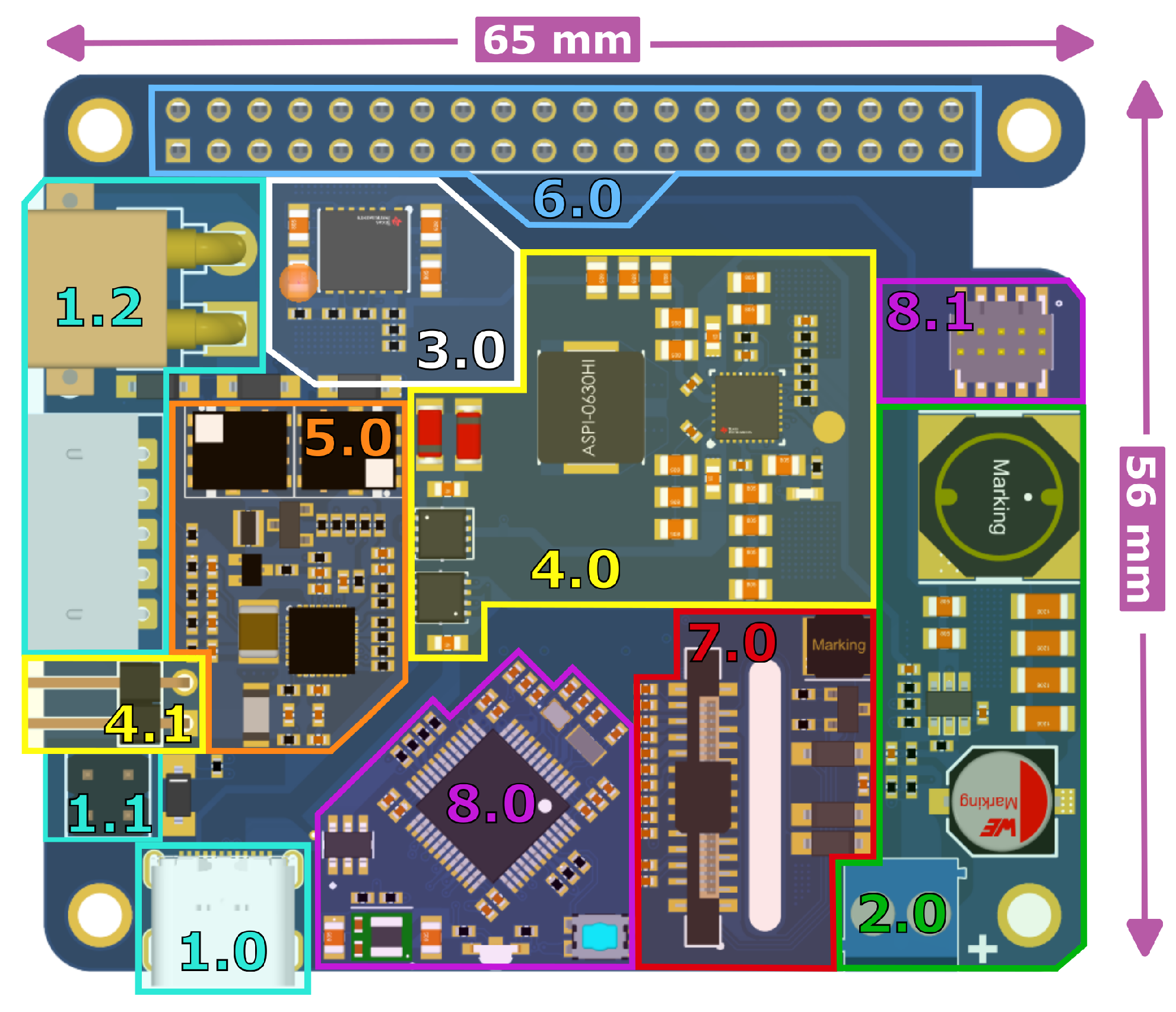
Figure 2 and
Figure 3 show the top and bottom views of the OptosenseCore PCB and the locations of the different components. OptosenseCore can be divided into nine major parts, whose numbers are referenced in the pictures below.
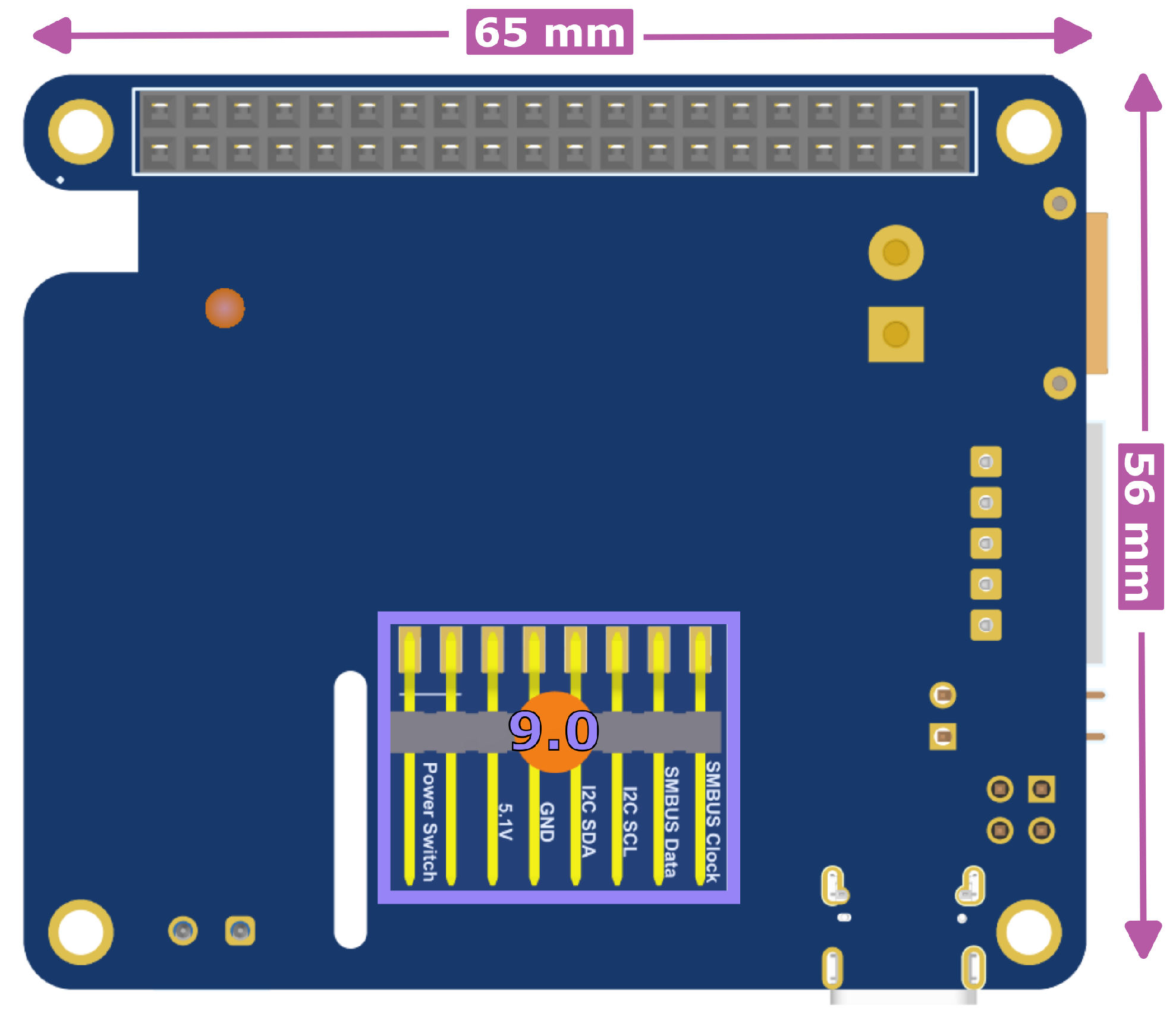
Power input: OptosenseCore provides different connectors that can be used to power the system. Feature 1.2 shows the connectors for a 4S lithium polymer (LiPo) battery. Feature 1.0 is a USB-C port that can be powered by every standard USB power delivery (USB-PD) source or even with a traditional USB-C power supply. Feature 1.1 highlights a 2 × 2 pin header that allows us to connect an external power source of up to 24 .
Voltage output: The power outlet is connected to an efficient DC/DC converter with a maximum current of 3
. The embedded microcontroller can switch the voltage output on and off and allows us to select output voltages in the range of 3–12 V if the selected input source provides enough power. The DC/DC converter output is controlled through the microcontroller’s digital-to-analog output by injecting a small current into the converter’s feedback, which is calculated as a function of the converter’s output voltage (ref. datasheet [
20]). To enhance the precision, the converter can either be dynamically controlled through a feedback loop or calibrated and then adjusted according to the resulting look-up table.
Power supply for Raspberry Pi: A DC/DC converter powers the Raspberry Pi with a stable voltage of to meet the computer’s power demands referenced in the previous chapter. The power module receives its input via one of the system’s available power sources.
Battery charger (and temperature sensor input): The battery is charged using a battery charger component and the USB-PD. If a suitable temperature sensor is connected, the battery charger can monitor the pack’s temperature while charging. The sensor can be attached to the angled two-pin header component featured in 4.1 of
Figure 2. The system can also be charged via the battery charger by connecting an external power source of up to 24
to the 2 × 2 pin header highlighted in Feature 1.1 of
Figure 2. This interface is also used to connect the PoE+ extension OptosensePoE.
Battery management system (BMS): A battery management system (BMS) that supports 500–65,000 mAh 4S-LiPo batteries enables the autonomous power supply of the system. The BMS monitors the connected battery and its behavior by, e.g., observing the voltage or cell level of each battery cell to estimate the remaining system runtime. Furthermore, the BMS is responsible for protecting the battery during charge and discharge cycles and for balancing the cell voltages.
Connection to Raspberry Pi: OptosenseCore features a dual row long pin header socket that compliments the Raspberry Pi’s default pin header and allows us to access the Raspberry Pi’s pins, even with a stacked-on OptosenseCore. Through this interface, OptosenseCore and the Raspberry Pi are connected and communicate using SPI (header pins 19, 21, 23, 24, and 26) and UART (header pins 8 and 10). For detailed information, reference design file OptosenseCore.PrjPcb from the repository (
supplementary, S1).
Connector for E-Ink display: Another connector provides an interface connected to the Raspberry Pi’s SPI peripheral to drive a
inch E-Ink module of the WaveShare family [
19] (Header pins 11, 18, and 22) and allows, e.g., the display of operational information.
Microcontroller and debugging connector: OptosenseCore features the embedded microcontroller STM32L5, which operates as a state machine and controls the systems components and voltage output. The microcontroller’s firmware can be updated and debugged using the attached debugging connector highlighted in Feature 8.1 of
Figure 2. A status LED is controlled by the microcontroller and encodes the system’s state, e.g., during battery charge operations.
Bottom connector: The bottom connector provides a pin pair to turn the device on and off via a push-button. This push-button also activates the Raspberry Pi power source using one of the microcontroller’s digital I/Os. Furthermore, additional debug pins allow us to access the I2C and SMBus systems. These pins can be used to access the charger or BMS with an external device, e.g., to calibrate the BMS.
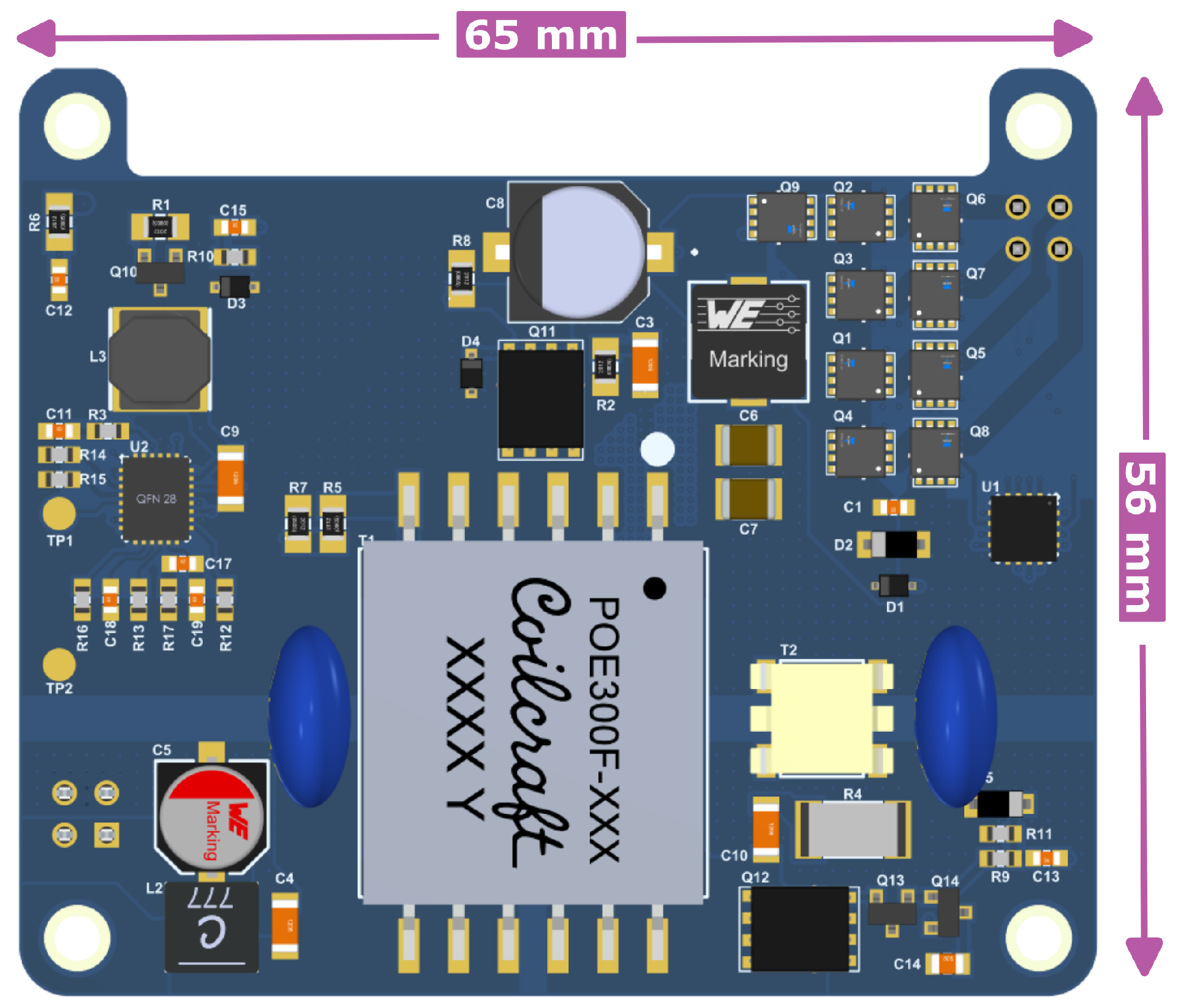
2.2. OptosensePoE
The PoE+ extension OptosensePoE provides an additional input source that delivers up to
of energy via PoE+ and hence provides a two-in-one solution for both network connectivity and power supply. The PoE+ extension is based on the 2584 A demonstration circuit board (ref. [
21]), essentially using the same circuitry and creating a new PCB that is compatible with the OptosenseCore module. The OptosensePoE PCB is shown in
Figure 4. OptosensePoE is stacked onto OptosenseCore and connected via the 2 × 2 pin header highlighted in Feature 1.1 of
Figure 2, essentially functioning as a 24
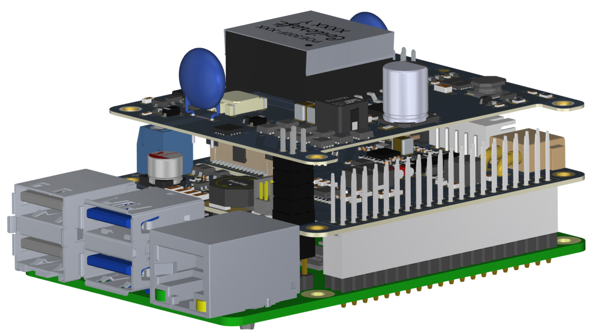
external power source. This implies that OptosensePoE can only be used in addition to OptosenseCore and not as a stand-alone application. A 3D model of the complete system consisting of the Raspberry Pi and both OptosenseCore and OptosensePoE stacked onto one another is shown in
Figure 5.
2.3. Optocubes Integration
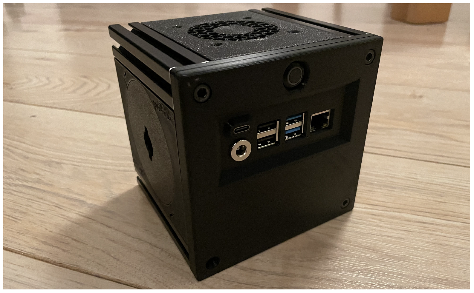
The complete system integrated into its Optocube housing is presented in
Figure 6 and features the Raspberry Pi stacked with both OptosenseCore and OptosensePoE, as well as a 4S2P-LiPo battery and a ventilator to cool down the system to provide adequate airflow for thermal stability. The ventilator is embedded into the housing’s top panel and powered by the Raspberry Pi’s supply voltage. The cube’s front panel incorporates cut-outs for the Raspberry Pi’s connectors, such as USB-A and ethernet, and OptosenseCore’s USB-C connector, as well as a power jack socket to access the adjustable voltage output. The front panel also includes the on/off button at the very top, which additionally indicates if the system is powered on by a blue LED ring.
The housing is based on the so-called ’breadboard bricks’ presented in [
17,
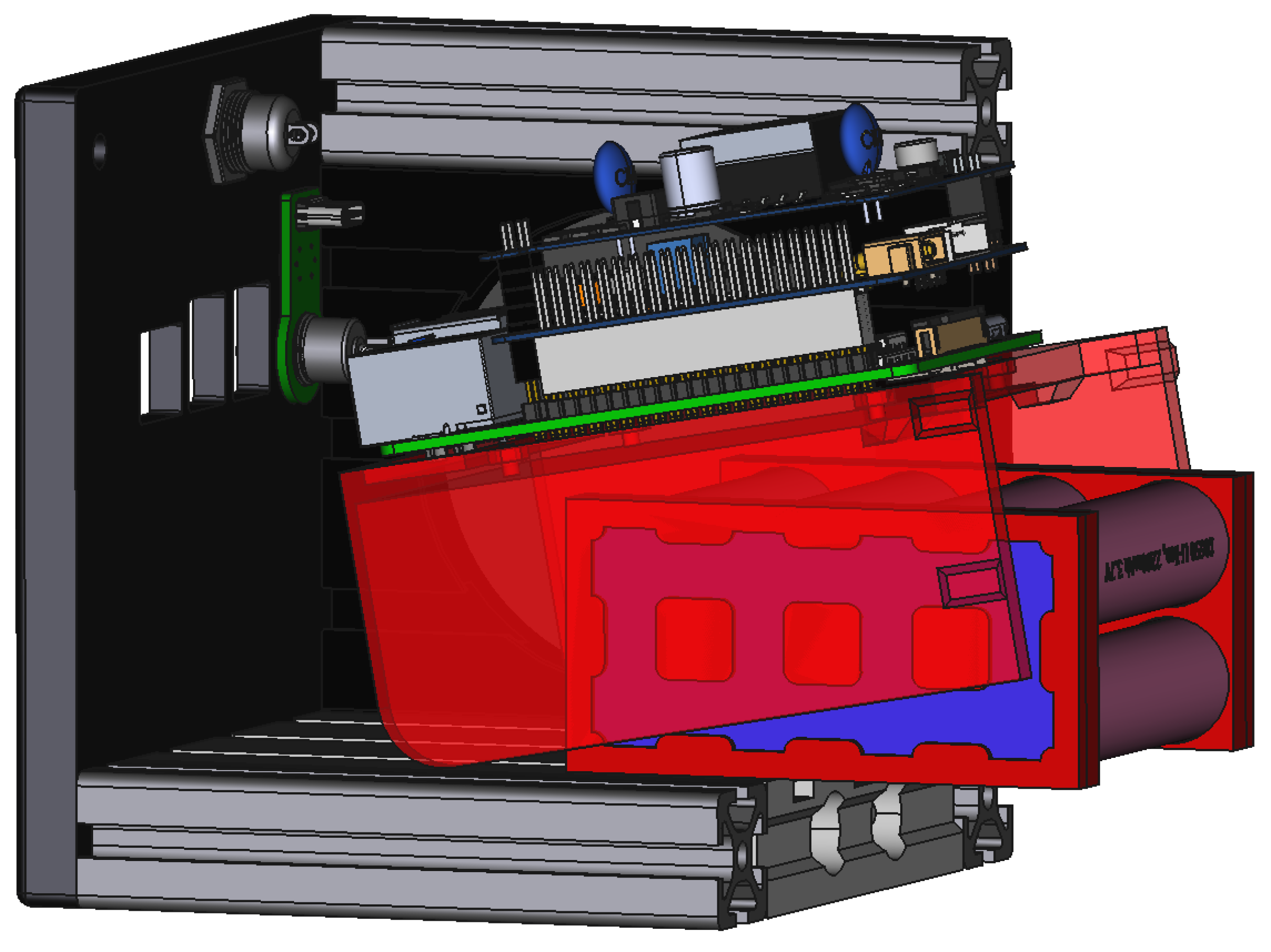
18], which is extended by a mechanical system to ease the access to and assembly of a self-sufficient IoT power solution. The mechanics involved are depicted in the 3D model in
Figure 7 and essentially involve two components. The first component is a 3D-printed elevation bracket, to which the Raspberry Pi, including the stacked OptosenseCore and OptosensePoE modules, is fixated by M2.5 screws. The bracket provides four protrusions that fit the Optocube’s side walls for guidance and hold it in place once the assembly is complete. The rounded corner on the bracket allows tilting when the bracket is partially pulled out of the Optocube, allowing access to the battery compartment in the space below the bracket. The battery, as the second component, is held in place by another protrusion at the elevation’s bottom and cannot be extracted without lifting the elevation, thus ensuring a stable assembly. Both mechanisms and their workings are illustrated in
Figure 7.
2.4. Safety
Since the system relies on LiPo batteries to power the overall system, it is necessary to consider safety procedures and to reduce the risk of user errors that could result in damage to the system or the user. First, the battery connectors use a standard XT-30 and JST-5-Pin layout to prohibit polarity reversal. Furthermore, the LiPo battery is protected by several additional features, such as temperature monitoring, cell balancing, overvoltage/undervoltage protection, and overcurrent protection. The combination of these features allows for the safe operation of the overall system with minimum risks.
3. Build Instructions
The OptosenseCore and OptosensePoE files for ordering the PCBs from a manufacturer are available in the repository (also
supplementary, S1) together with the detailed bills of materials. There are PCB manufacturers that offer to assemble the electrical components when ordering a PCB. The costs for both PCBs at the time of writing this paper are estimated at:
| OptosenseCore | EUR 109.76 |
| OptosensePoE | EUR 80.68 |
The electrical circuit and PCB were designed with Altium Designer. Modifying the PCB requires the Altium Designer application.
Operating the overall system requires a Rasperry Pi 3 B+ or Raspberry Pi 4. OptosenseCore was devised in such a way that it can be easily stacked onto the Raspberry Pi’s HATs without needing to consider other connectors, thus reducing human errors when assembling the system. OptosensePoE is designed to be easily stacked onto the OptosenseCore using the same principle. For a detailed view of the stacking principle and the assembled PCBs, refer to
Figure 2,
Figure 3,
Figure 4,
Figure 5 and
Figure 8, respectively.
The physical assembly of the system furthermore necessitates access to and experience with using a 3D printer and the associated PC software, for example, PrusaSlicer (version 2.7.1). Modification of the 3D designs relies on the availability of the PC software FreeCAD (version 0.21.1). The 3D printing files for the system’s housing and the self-assembled battery pack, as presented in this article, are accessible in the repository (
supplementary, S6). The assembly of the complete system, consisting of the Raspberry Pi, PCBs, battery and housing, can be derived from
Section 2.3 and, in particular, from
Figure 7.
Once calibrated, any 4S LiPo battery configuration with 500–65,000 mAh is allowed, whether self-assembled or commercially available, and can be connected to OptosenseCore using the standard XT-30 and JST-5 pin layout so polarity reversal is prohibited.
4. Operating Instructions
4.1. Calibration Gauge
When using a battery, the integrated gauge requires calibration to estimate the battery’s capacity and to calculate accurate values for the battery runtime and charging time. Configuring and calibrating the BMS unit on OptosenseCore is carried out using the PC software BQStudio, version 1.3.101.1, developed by Texas Instruments. The usuage of BQStudio requires a developing tool, such as EV2300/EV2400 by Texas Instruments, to communicate with the hardware. The instructions are explained step-by-step in the document “How to Complete a Successful Learning Cycle for the bq40z80” [
22]. Calibration is carried out by connecting a programmer (e.g., ST-Link/V2 or J-Link EDU Mini) to the 1 × 8 pin header on the bottom of OptosenseCore’s PCB (see Feature 9.0 of
Figure 3) and using the SMBus protocol. Detailed information on the pinout can be found in the repository’s schematics (
supplementary, S1, S4).
4.2. Software Operations
The firmware for OptosenseCore’s microcontroller was developed using the integrated development environment (IDE) STM32CubeIDE version 1.6.1, which can also be used for debugging purposes. The microcontroller can be programmed using this or any other suitable IDE and an additional program/debug probe, such as the ST-Link/V2 or J-Link EDU Mini. The controller firmware file and corresponding source code are also available in the repository (
supplementary, S3).
The Raspberry Pi can be used to run IBM’s Node-RED [
23], which allows one to assemble simple flow diagrams to interact with OptosenseCore. For this, Node-RED 2.0, Node.js 16.16.0 and Raspberry OS need to be installed on the Raspberry Pi to use the graphical user interface presented below. Raspberry OS can be used with or without the desktop environment package. For detailed information on how to install the aforementioned software packages, refer to [
24,
25]. Additionally, the graphical user interface requires one to install the Node-RED module
node-red-dashboard (version 3.6.2) and the Optosense Nodes presented in the previous section. These nodes are accessible via the repository (
supplementary, S2) and can be easily added following the instructions in [
26]. We advise for the Raspberry Pi to have an internet connection to allow for all dependencies of the packages to be installed properly. Furthermore, we recommend the use of an SD card with a minimum of 8 GB of space.
To simplify the first steps and the assembly of individual Node-RED flows, we provide pre-configured nodes to operate the system. These nodes read device information and battery details from OptosenseCore’s
BMS and allow one to set the output voltage of OptosenseCore’s voltage output. The nodes and their respective attributes are shown in
Table 2,
Table 3 and
Table 4.
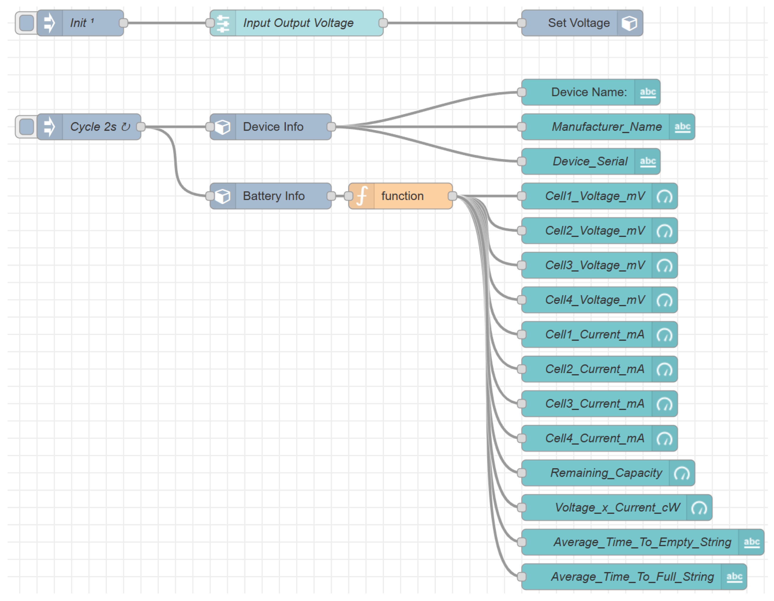
The nodes’ output data can be displayed in Node-RED’s graphical user interface (GUI).
Figure 9 is a simple exemplary Node-RED flow for retrieving the system’s device and battery data every two seconds and presenting the information in a GUI using different nodes. The picture also shows the use of the node
Set Voltage, whose input value is changed by a slider in the GUI to enable the user to adjust OptosenseCore’s voltage output. The slider can be seen in the example GUI that uses the
node-red-dashboard [
27] module and is shown in
Figure 10 and
Figure 11.
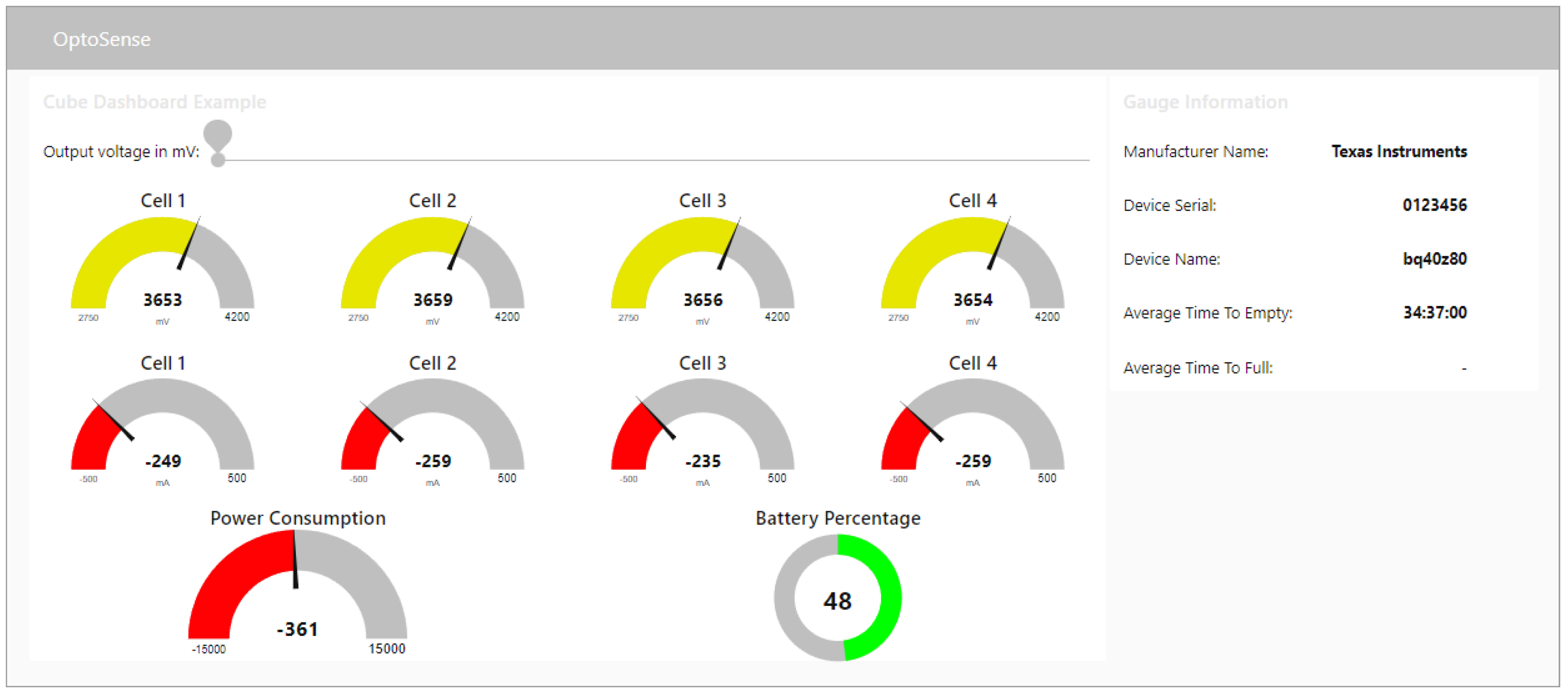
The GUI depicted in
Figure 10 and
Figure 11 presents a variety of graphical elements displaying the system’s information communicated to the Raspberry Pi by OptosenseCore’s microcontroller via their SPI interface. The user interface can be individually adjusted according to the user’s requirements using Node-RED flows and the three nodes described above. The example shown in
Figure 10 features the aforementioned slider for adjusting the voltage of OptosenseCore’s voltage output and a list of information on the BMS, such as the manufacturer name, the serial number or the estimated time until the battery is fully charged or discharged. In addition, there is information on every serial element of the battery pack via the balancer connection. Obviously, monitoring each of the parallel cells would require extensive rewiring of the pack and is generally not implemented in commercially available BMS solutions.
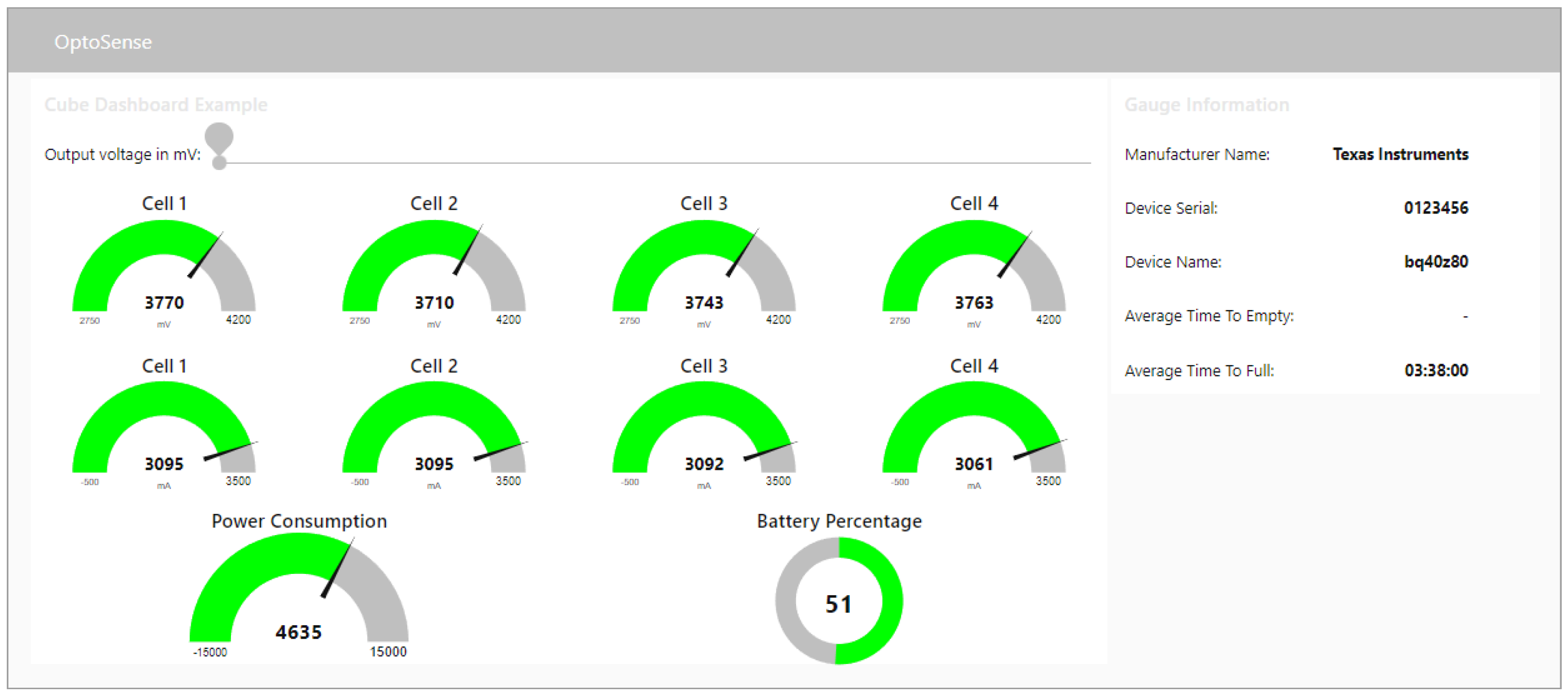
Figure 10 shows an example of the provided data during battery discharge, whereas
Figure 11 shows the battery information during a charge cycle.
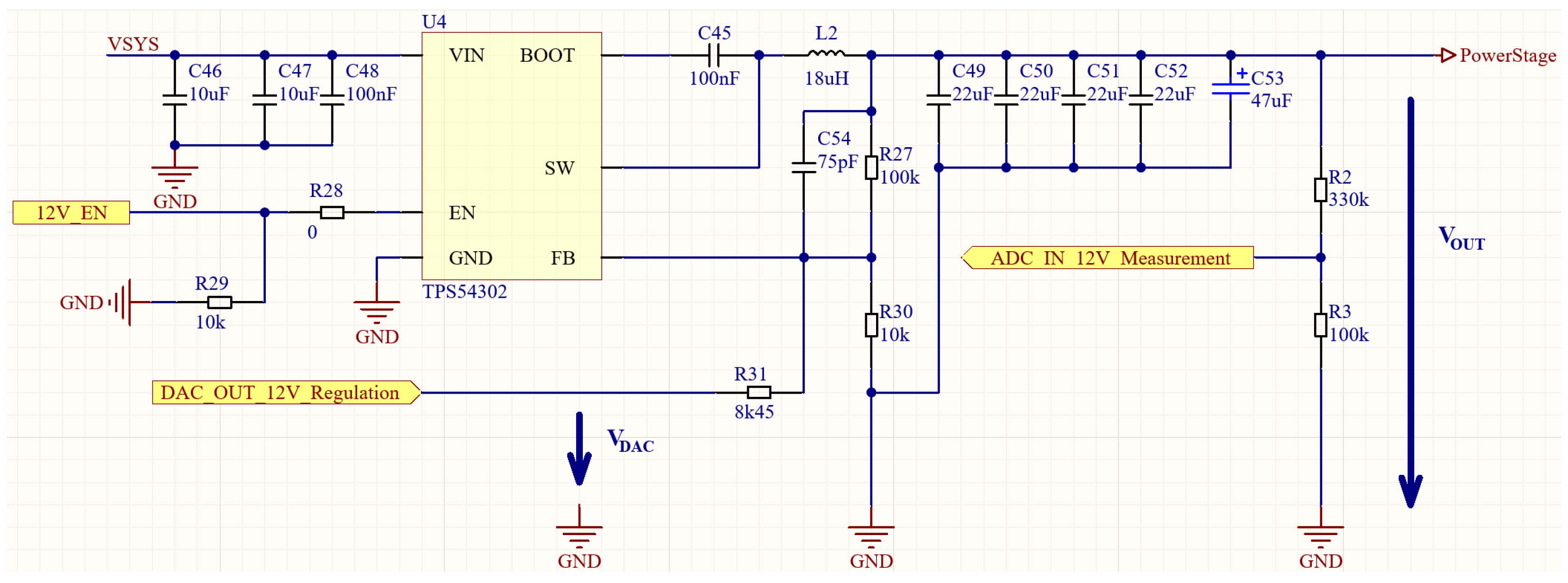
4.3. Calibration Adjustable Power Supply
While the integrated and adjustable power supply provides a high-precision output voltage, a calibration is required if higher accuracy of the output voltage is needed. This step is optional and only necessary if the intended application requires a more precise power supply selection. Theoretically, the output voltage is generated using a DC/DC converter with a DAC connected to its feedback loop through a resistor. The resulting target value is calculated using Equation (
1). To counter differences in the calculated and actual values, due to possible inaccuracies of the electrical components forming the circuit, a second feedback loop to the micro-controller’s ADC is implemented to allow measurements of the real voltage output for either controlling the value dynamically or for using this closed-loop circuit to calibrate the system and to generate a look-up table. The circuit is shown in detail in
Figure 12.
The equation describing the DAC voltage as a function of the DC/DC output voltage using the notation of the electrical circuit in
Figure 12 is as follows:
as provided by [
20,
28].
5. Validation
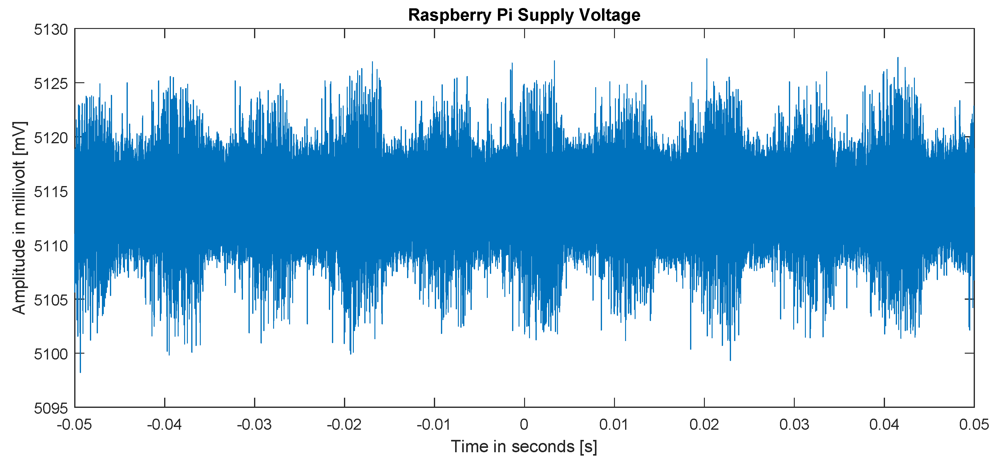
A variety of different scenarios were tested to validate OptosenseCore’s operability. First, the stability of the Raspberry Pi power supply was analyzed using the 500
HDO6054A-MS oscilloscope (firmware version 8.5.0.5, build 240488) by Teledyne LeCroy [
29].
Figure 13 shows the Raspberry Pi’s power supply voltage as measured on the oscilloscope. The mean voltage amounts to approximately
, thus verifying the delivery of a steady power supply for powering the Raspberry Pi. In this test setup, the battery was used to power OptosenseCore and the Raspberry Pi. However, other supply options were tested as well (e.g., USB-C, PoE+ or external power supply) and yielded comparable results.
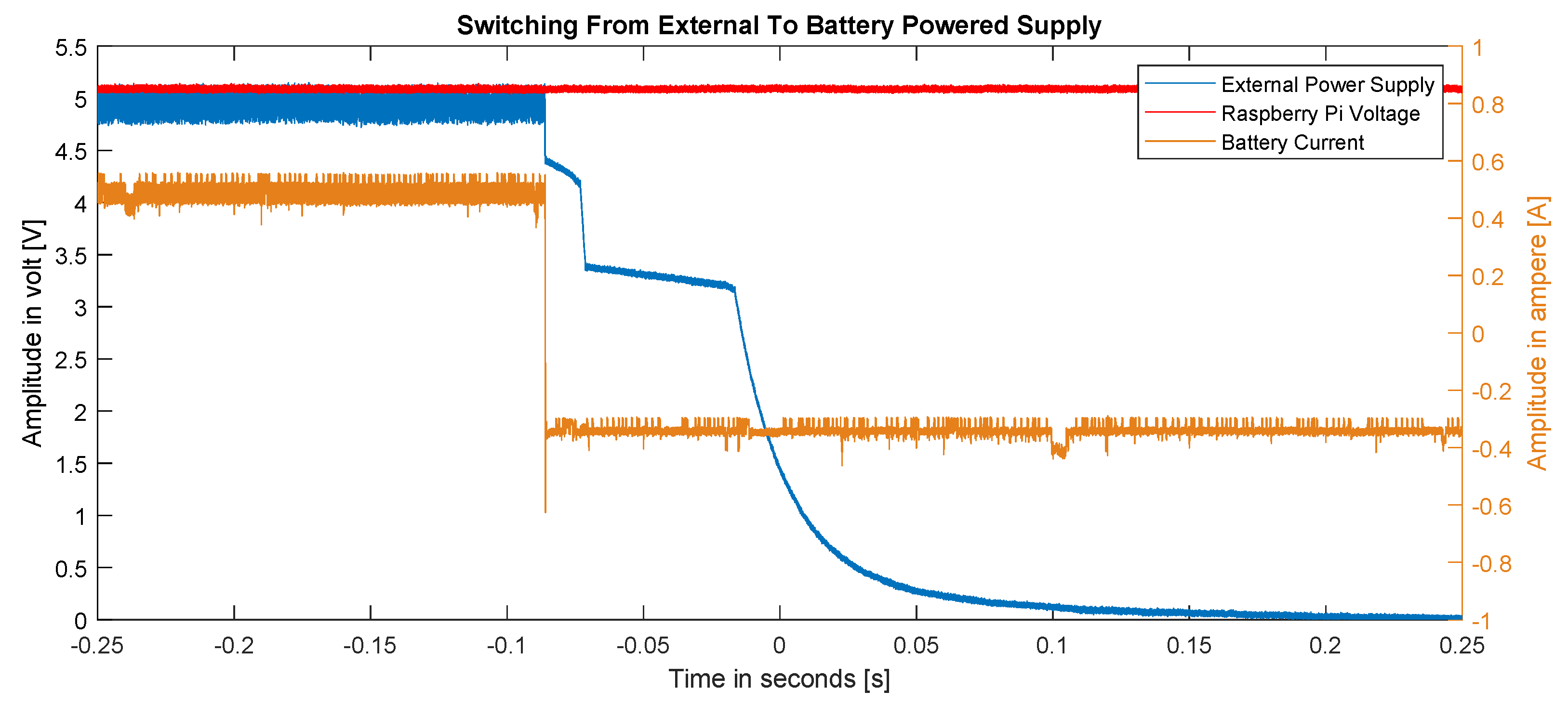
The second test shows the working of the uninterruptible power supply (UPS), which is the battery’s overtake once the main energy source fails. For this test setup, the system was first powered using a 5
USB-C power adapter, which was then disconnected.
Figure 14 shows the exact moment of disconnect and demonstrates the battery taking over the power supply, resulting in uninterrupted power delivery to the Raspberry Pi. The measurement was taken using the same Teledyne LeCroy oscilloscope mentioned above plus the corresponding CP030A [
30] current probe. When the external power supply voltage dropped at approx.
s, the direction of the battery’s current flow changed immediately, as it switched from being charged to being discharged. The Raspberry Pi supply voltage remained a steady
throughout this procedure, thus demonstrating the functionality of the UPS feature.
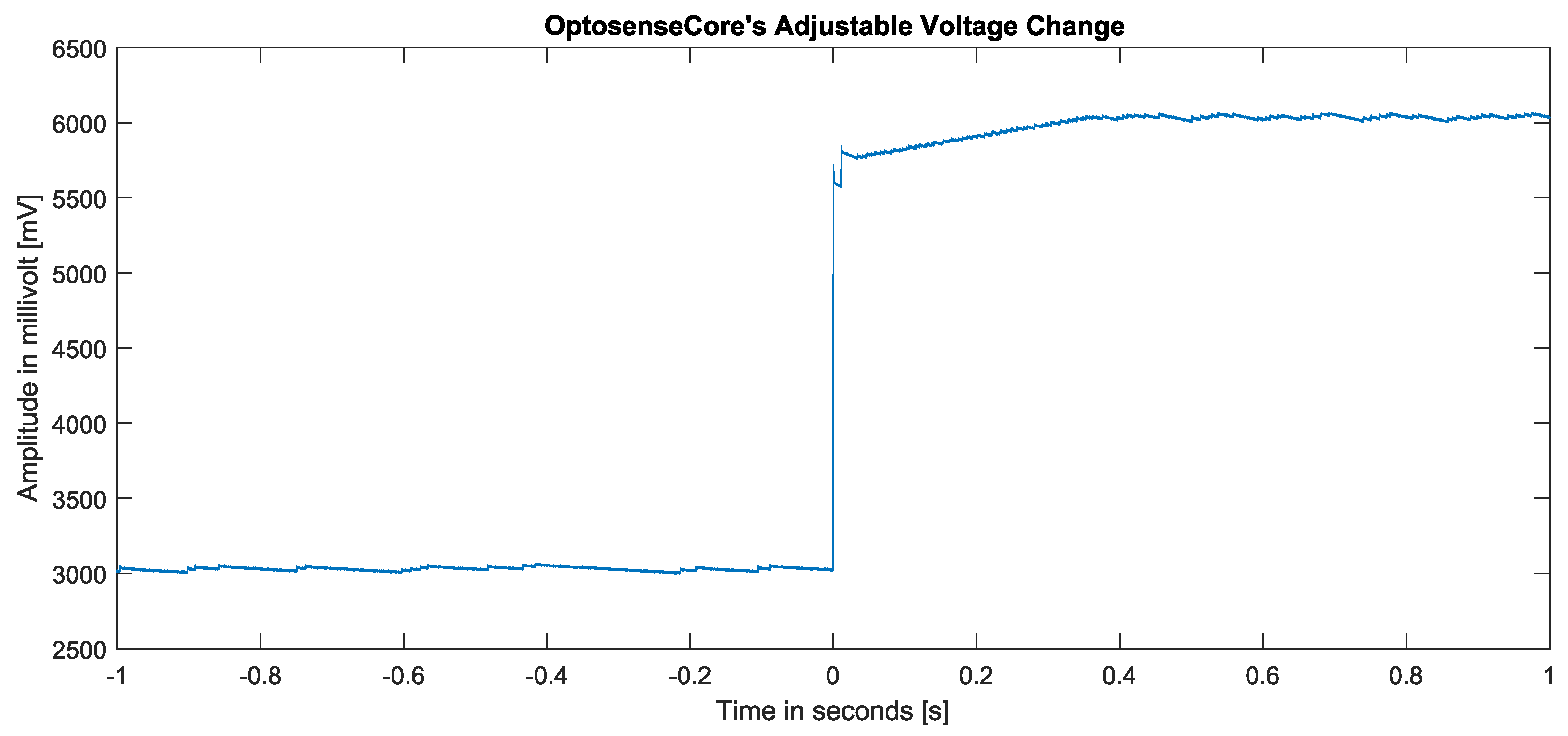
The third test setup examined the stability and precision of OptosenseCore’s adjustable voltage output. An electric load was connected to the voltage output, and the voltage was adjusted using the Node-RED user interface.
Figure 15 shows the output voltage while increasing the set-point value from
to
. The adjustment was made gradually over a period of
s.
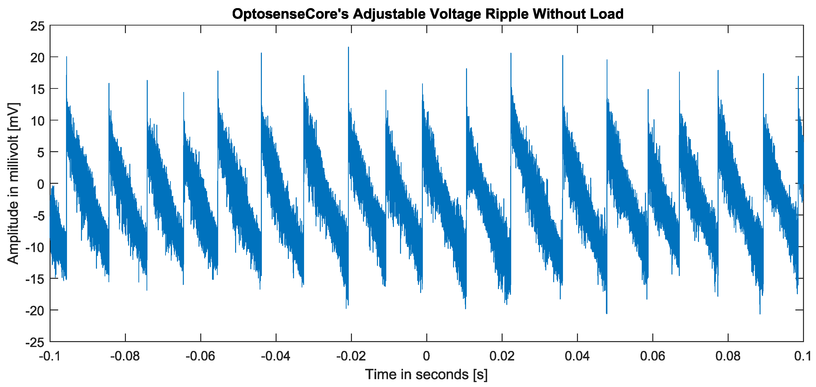
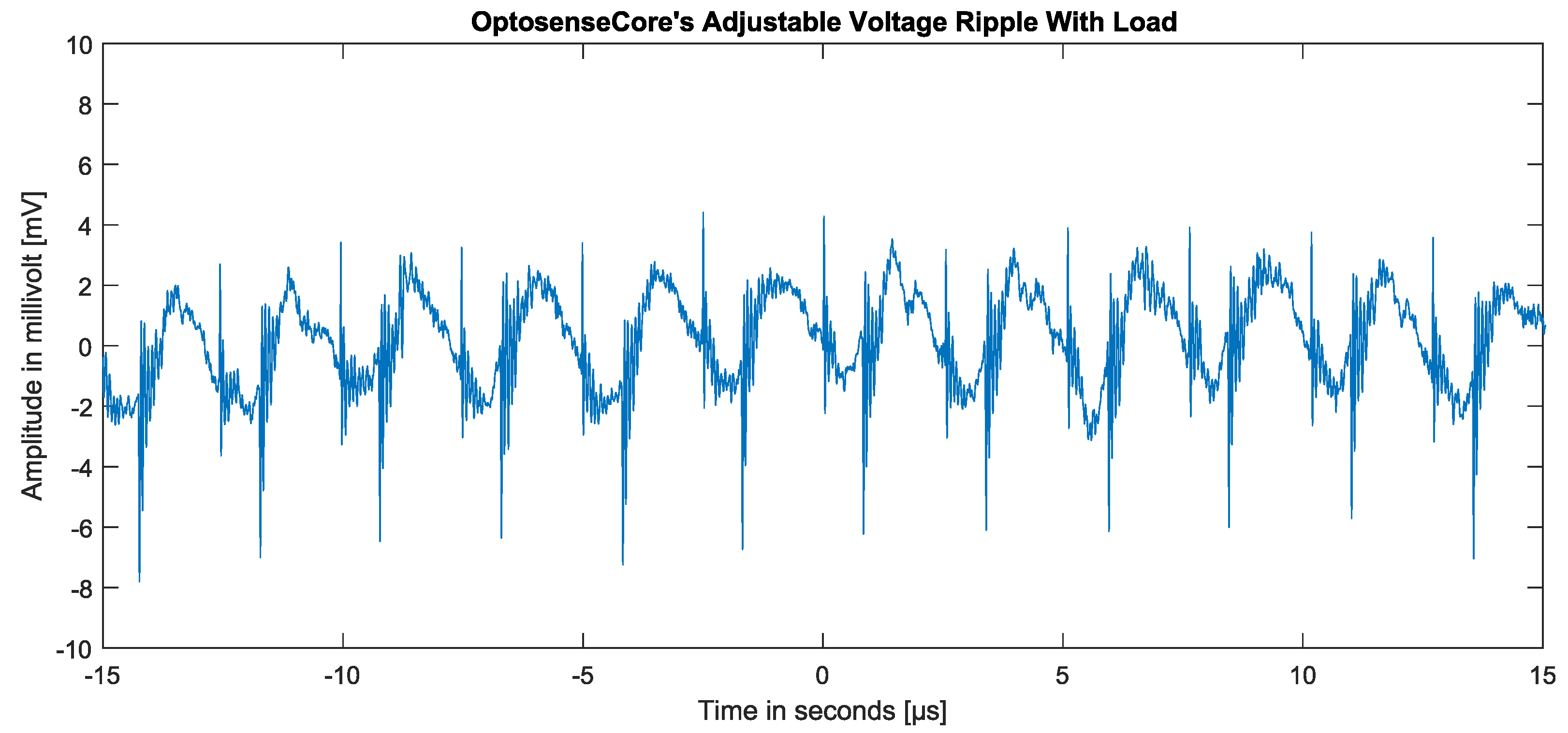
Although the overall output voltage was quite stable, the DC/DC converter that sets the voltage caused an AC ripple overlay due to its internal switching operations and its configuration. This ripple is shown in
Figure 16 and ranges between
and 20
.
Figure 17 shows the ripple with an electrical load. This amount of AC voltage matches the values listed in the datasheet (ref. [
20]) and is manageable by most appliances. If an application needs an even more steady voltage supply, the ripple can be further reduced using external filtering.
Since OptosensePoE is entirely based on the already existing 2584A demonstration circuit board, we present no further validation for this module and instead refer to the DC2584A-A demo manual (ref. [
21]).
6. Conclusions
This paper introduces the design of a low-cost, open-source battery management system with various power-sourcing solutions for Raspberry Pi applications. Wired power sourcing is available via PoE+, USB-PD, or any power adapter with up to 24 via a 2 × 2 pin header. The mobile operation mode is supported by s 4S-LiPo battery of 500–65,000 mAh, which can be charged by any of the aforementioned wired power sources. An additional feature is the fail-safe functionality of the 4S-LiPo battery, also referred to as an uninterruptible power supply (UPS), which is automatically active when the battery is connected and enables a steady supply of even if the network connection is broken as long as the battery is charged. This makes the system adaptable to a variety of environments and use cases.
The safety of the system is secured by adapting a multitude of protective features, such as temperature monitoring, cell balancing, over-voltage/under-voltage protection, and over-current protection.
Furthermore, the system is equipped with an integrated adjustable power output to supply arbitrary peripherals with up to 12 . This voltage is superimposed by a ripple in the range of −20 mV to 20 mV, caused by the DC/DC converter used, and can be further reduced by appropriate external filters, if required.
An embedded E-Ink driver supports the Waveshare 12563 2.9inch E-Ink display, which can be used to show relevant information, e.g., metadata or a QR code to access the Raspberry Pi’s WiFi network. The complete system is designed to be easily assembled and compact and to fit in a mm cube that can be partially 3D printed. At the time of writing this paper, the costs for the system amount to EUR 109.76 or EUR 190.44 in total when including the PoE option. The system’s user interface is based on Node-RED and allows communication through a dashboard. This paper presents pre-programmed Node-RED nodes to access the hardware for easy commissioning of the system.
The Raspberry Pi is a popular IoT device and is already used in a variety of projects. We believe that the versatility of the developed system is able to facilitate and enhance a multitude of new or present Raspberry Pi setups, for example, by offering a solution for mobile applications to run for an extended period of time using the battery system or by providing an integrated power source to drive additional electronics. Another such potential is the flexibility in powering the system. Especially in industrial environments, where power sources might be limited, this provides a huge advantage. The ability of the battery to work as a fail-safe system and to bridge possible power outages by seamlessly taking over the energy supply further enhances the system’s adaptability to a variety of challenging environments where Raspberry Pi applications might want to be used. The scalability of the battery’s capacity furthermore promotes its adaptability to different requirements.
Supplementary Materials
The following supporting information can be downloaded at:
https://www.mdpi.com/article/10.3390/hardware1010005/s1, Archive S1: OptosenseCore and OptosensePoE. Archive S2: Optosense Nodes. Archive S3: OptosenseCore firmware. Figure S4: OptosenseCore schematic. Figure S5: OptosensePoE schematic. CAD S6: Optosense cube housing.
| Name | Type | Description |
| S1 | Archive (.zip) | PCB Design Files |
| S2 | Archive (.zip) | OptosenseCore Nodes |
| S3 | Archive (.zip) | OptosenseCore Firmware/Source code |
| S4 | Document (.pdf) | OptosenseCore schematic |
| S5 | Document (.pdf) | OptosensePoE schematic |
| S6 | FreeCAD (.FCStd) | CAD Housing Design |
Author Contributions
Conceptualization, D.P.H. and D.B.; methodology, D.P.H.; software, D.P.H.; validation, D.P.H.; resources, D.B.; writing—original draft preparation, D.P.H.; writing—review and editing, D.B.; visualization, D.P.H.; supervision, D.B.; project administration, D.B. All authors have read and agreed to the published version of the manuscript.
Funding
This work was supported by the German Federal Ministry of Education and Research (BMBF) as part of the project Optocubes within the funding program “Photonics Research Germany” [contract number 13N15230].
Institutional Review Board Statement
Not applicable.
Informed Consent Statement
Not applicable.
Data Availability Statement
Conflicts of Interest
The authors declare no conflict of interest.
Abbreviations
The following abbreviations are used in this manuscript:
| IoT | Internet of Things |
| PoE | Power over Ethernet |
| GUI | Graphical user interface |
| BMS | Battery management system |
| ADC | Analog–digital converter |
| DAC | Digital–analog converter |
| UPS | Uninterruptible power supply |
| LED | Light-emitting diode |
| LiPo | Lithium polymer |
| USB | Universal Serial Bus |
| USB-PD | USB Power Delivery |
References
- Raspberry Pi. Buy a Raspberry Pi 4 Model B—Raspberry Pi. Available online: https://www.raspberrypi.org/products/raspberry-pi-4-model-b (accessed on 1 November 2023).
- Meddeb, H.; Abdellaoui, Z.; Houaidi, F. Development of surveillance robot based on face recognition using Raspberry-PI and IOT. Microprocess. Microsyst. 2023, 96, 104728. [Google Scholar] [CrossRef]
- Mathe, S.E.; Pamarthy, A.C.; Kondaveeti, H.K.; Vappangi, S. A Review on Raspberry Pi and its Robotic Applications. In Proceedings of the 2022 2nd International Conference on Artificial Intelligence and Signal Processing (AISP), Vijayawada, India, 12–14 February 2022; pp. 1–6. [Google Scholar]
- Horak, K.; Zalud, L. Image Processing on Raspberry Pi for Mobile Robotics. Int. J. Signal Process. Syst. 2016, 4, 494–498. [Google Scholar]
- Jolles, J.W. Broad-scale applications of the Raspberry Pi: A review and guide for biologists. Methods Ecol. Evol. 2021, 12, 1562–1579. [Google Scholar] [CrossRef]
- Wandel, T.; Hausherr, D.P.; Berben, D. Measuring Suite for Vascular Response Monitoring during Hyperbaric Oxygen Therapy by Means of Pulse Transit Time (PTT) Analysis. Sensors 2022, 22, 8295. [Google Scholar] [CrossRef] [PubMed]
- Gupta, M.S.D.; Patchava, V.; Menezes, V. Healthcare based on IoT using Raspberry Pi. In Proceedings of the 2015 International Conference on Green Computing and Internet of Things (ICGCIoT), Greater Noida, India, 8–10 October 2015; pp. 796–799. [Google Scholar]
- Pardeshi, V.; Sagar, S.; Murmurwar, S.; Hage, P. Health monitoring systems using IoT and Raspberry Pi—A review. In Proceedings of the 2017 International Conference on Innovative Mechanisms for Industry Applications (ICIMIA), Piscataway, NJ, USA, 21–23 February 2017; pp. 134–137. [Google Scholar]
- Kumar, R.; Rajasekaran, M.P. An IoT based patient monitoring system using raspberry Pi. In Proceedings of the 2016 International Conference on Computing Technologies and Intelligent Data Engineering (ICCTIDE’16), Kovilpatti, India, 7–9 January 2016; pp. 1–4. [Google Scholar]
- Gupta, I.; Patil, V.; Kadam, C.; Dumbre, S. Face detection and recognition using Raspberry Pi. In Proceedings of the 2016 IEEE International WIE Conference on Electrical and Computer Engineering (WIECON-ECE), Pune, India, 19–21 December 2016; pp. 83–86. [Google Scholar]
- Sforzin, A.; Marmol, F.G.; Conti, M.; Bohli, J.M. RPiDS: Raspberry Pi IDS—A Fruitful Intrusion Detection System for IoT. In Proceedings of the 2016 Intl IEEE Conferences on Ubiquitous Intelligence & Computing, Advanced and Trusted Computing, Scalable Computing and Communications, Cloud and Big Data Computing, Internet of People, and Smart World Congress (UIC/ATC/ScalCom/CBDCom/IoP/SmartWorld), Toulouse, France, 18–21 July 2016; pp. 440–448. [Google Scholar]
- Ansari, A.N.; Sedky, M.; Sharma, N.; Tyagi, A. An Internet of things approach for motion detection using Raspberry Pi. In Proceedings of the 2015 International Conference on Intelligent Computing and Internet of Things, Harbin, China, 17–18 January 2015; pp. 131–134. [Google Scholar]
- Billa, P.; Venkatesh, K.; Venkata Sai, J.; Lohith, K.; Sampath Kumar, A. Effective monitoring and protecting system for agriculture farming using IoT and raspberry pi. Mater. Today Proc. 2023, 80, 2917–2920. [Google Scholar] [CrossRef]
- Nikhade, S.G. Wireless sensor network system using Raspberry Pi and zigbee for environmental monitoring applications. In Proceedings of the 2015 International Conference on Smart Technologies and Management for Computing, Communication, Controls, Energy and Materials (ICSTM), Avadi, India, 6–8 May 2015; pp. 376–381. [Google Scholar]
- Shete, R.; Agrawal, S. IoT based urban climate monitoring using Raspberry Pi. In Proceedings of the 2016 International Conference on Communication and Signal Processing (ICCSP), Melmaruvathur, India, 6–8 April 2016; pp. 2008–2012. [Google Scholar]
- BMBF Open-Innovation. Optocubes—Open Source Systembaukasten für das Agile Prototyping Laserbasierter Sensoren. Available online: https://www.photonikforschung.de/projekte/open-innovation/projekt/optocubes.html (accessed on 1 November 2023).
- Toschke, Y.; Bourdon, B.; Berben, D.; Imlau, M. A modular optical honeycomb breadboard realized with 3D-printable building bricks and industrial aluminum extrusions. HardwareX 2021, 9, e00182. [Google Scholar] [CrossRef] [PubMed]
- Bourdon, B.; Toschke, Y.; Osterheider, M.; Imlau, M. The Optocubes Project: Modular Construction Framework. 2023. Available online: https://osnadata.ub.uni-osnabrueck.de/dataset.xhtml?persistentId=doi:10.26249/FK2/WOFNVD (accessed on 1 November 2023).
- Waveshare. WaveShare 2.9inch E-Ink display. Available online: https://www.waveshare.com/2.9inch-e-paper.htm (accessed on 1 November 2023).
- Texas Instruments. TPS54302 DC/DC Converter Datasheet. Available online: https://www.ti.com/lit/ds/symlink/tps54302.pdf (accessed on 1 November 2023).
- Analog Devices. High Efficiency IEEE 802.3bt (PoE++, Type 4, 71W) PD with Forward DC/DC Converter. Available online: https://www.analog.com/media/en/technical-documentation/user-guides/dc2584aafa.pdf (accessed on 1 November 2023).
- Texas Instruments. How to Complete a Successful Learning Cycle for the bq40z80. Available online: https://www.ti.com/lit/an/slua848/slua848.pdf (accessed on 1 November 2023).
- NodeRED. Node-RED Low-Code Programming for Event-Driven Applications. Available online: https://nodered.org (accessed on 1 November 2023).
- Raspberry Pi. Getting Started with Your Raspberry Pi. Available online: https://www.raspberrypi.com/documentation/computers/getting-started.html (accessed on 1 November 2023).
- NodeRED. Node-RED Getting Started on Raspberry Pi. Available online: https://nodered.org/docs/getting-started/raspberrypi (accessed on 1 November 2023).
- NodeRED. Adding Nodes to the Palette. Available online: https://nodered.org/docs/user-guide/runtime/adding-nodes (accessed on 1 November 2023).
- NodeRED. Node-Red-Dashboard—A set of Dashboard Nodes for Node-RED. Available online: https://flows.nodered.org/node/node-red-dashboard (accessed on 1 November 2023).
- Texas Instruments. Methods of Output-Voltage Adjustment for DC/DC Converters. Available online: https://www.ti.com/lit/an/slyt777/slyt777.pdf (accessed on 1 November 2023).
- Teledyne LeCroy. HDO6000A Oscilloscopes Datasheet. Available online: https://cdn.teledynelecroy.com/files/pdf/hdo6000a-oscilloscopes-datasheet.pdf (accessed on 1 November 2023).
- Teledyne LeCroy. CP030A Current Probe Datasheet. Available online: https://cdn.teledynelecroy.com/files/pdf/current-probes-datasheet.pdf (accessed on 1 November 2023).
Figure 1.
Schematic overview of the interfaces and internal connections between OptosenseCore’s components.
Figure 1.
Schematic overview of the interfaces and internal connections between OptosenseCore’s components.
Figure 2.
Top view of OptosenseCore’s PCB with its major parts.
Figure 2.
Top view of OptosenseCore’s PCB with its major parts.
Figure 3.
Bottom view of OptosenseCore’s PCB with its connectors.
Figure 3.
Bottom view of OptosenseCore’s PCB with its connectors.
Figure 4.
Optosense’s PoE+ extension.
Figure 4.
Optosense’s PoE+ extension.
Figure 5.
A 3D model of a Raspberry Pi stacked with both extensions.
Figure 5.
A 3D model of a Raspberry Pi stacked with both extensions.
Figure 6.
Photograph of the assembled Optocube housing with integrated Raspberry Pi, OptosenseCore module, OptosensePoE module, battery, ventilator, and connectors.
Figure 6.
Photograph of the assembled Optocube housing with integrated Raspberry Pi, OptosenseCore module, OptosensePoE module, battery, ventilator, and connectors.
Figure 7.
A 3D model of the assembled Optocube housing showing the mechanics of the internal assembly.
Figure 7.
A 3D model of the assembled Optocube housing showing the mechanics of the internal assembly.
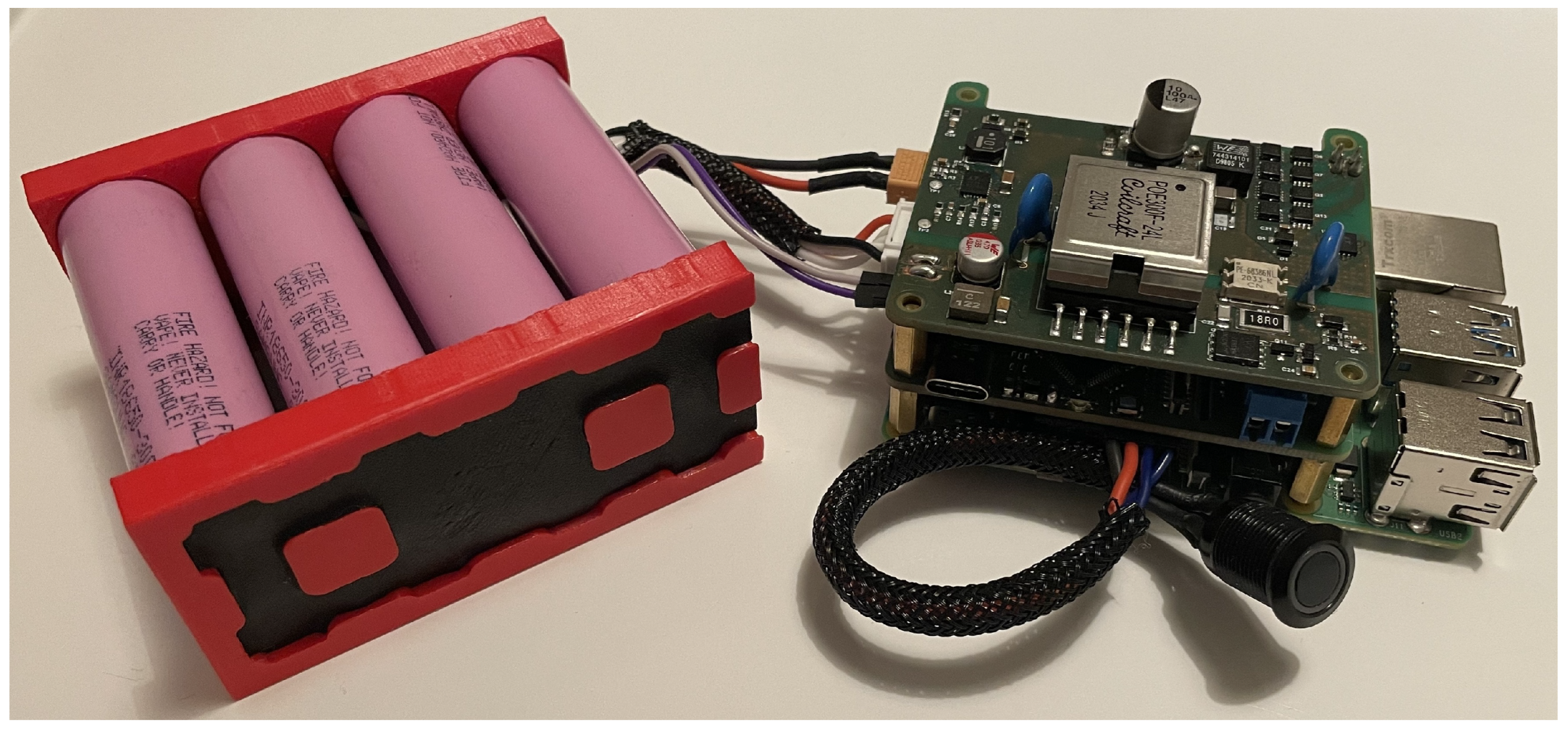
Figure 8.
Raspberry Pi with mounted OptosenseCore PCB, battery pack, battery activation button, and temperature sensor.
Figure 8.
Raspberry Pi with mounted OptosenseCore PCB, battery pack, battery activation button, and temperature sensor.
Figure 9.
Example Node-RED flow using nodes 1–3.
Figure 9.
Example Node-RED flow using nodes 1–3.
Figure 10.
Example Node-RED user interface using the example flow in
Figure 9 during discharge.
Figure 10.
Example Node-RED user interface using the example flow in
Figure 9 during discharge.
Figure 11.
Example Node-RED user interface using the example flow in
Figure 9 during charge.
Figure 11.
Example Node-RED user interface using the example flow in
Figure 9 during charge.
Figure 12.
Electrical circuit of the DC/DC converter providing adjustable power output.
Figure 12.
Electrical circuit of the DC/DC converter providing adjustable power output.
Figure 13.
Oscilloscope measurement showing the stability of the Raspberry Pi’s power supply.
Figure 13.
Oscilloscope measurement showing the stability of the Raspberry Pi’s power supply.
Figure 14.
Oscilloscope measurement showing the functionality of the UPS feature.
Figure 14.
Oscilloscope measurement showing the functionality of the UPS feature.
Figure 15.
Oscilloscope measurement demonstrating the stability of the adjustable output voltage during on-load operations.
Figure 15.
Oscilloscope measurement demonstrating the stability of the adjustable output voltage during on-load operations.
Figure 16.
Output ripple of the adjustable voltage output caused by the DC/DC converter without load.
Figure 16.
Output ripple of the adjustable voltage output caused by the DC/DC converter without load.
Figure 17.
Output ripple of the adjustable voltage output caused by the DC/DC converter with a load of 500 mA.
Figure 17.
Output ripple of the adjustable voltage output caused by the DC/DC converter with a load of 500 mA.
Table 1.
LED behaviour description of device states.
Table 1.
LED behaviour description of device states.
| Device State | LEDred | LEDgreen |
|---|
| Normal | Off | On |
| Charging | Blinking (T = 2 s) | Off |
| Error | Blinking (T = 0.5 s) | Blinking (T = 0.5 s) |
Table 2.
Attributes of the node Device Info.
Table 2.
Attributes of the node Device Info.
| Node | I/O | Attribute Name | Type | Info |
|---|
![Hardware 01 00005 i001]() | O | Device_Manufacturer | String | — |
| O | Device_Name | String | — |
| O | Device_Serial | String | — |
Table 3.
Attributes of the node Battery Info.
Table 3.
Attributes of the node Battery Info.
| Node | I/O | Attribute Name | Type | Info |
|---|
![Hardware 01 00005 i002]() | O | Cell[X]_Voltage_mV | Number | X = 1–4 |
| O | Cell[X]_Current_mA | Number | X = 1–4 |
| O | Cell[X]_Power_cW | Number | X = 1–4 |
| O | Voltage_x_Current_cW | Number | — |
| O | BAT_Voltage_mV | Number | — |
| O | PACK_Voltage_mV | Number | — |
| O | Average_Power_cW | Number | — |
| O | Remaining_Capacity | Number | — |
| O | Full_Charge_Capacity | Number | — |
| O | Runtime_To_Empty | Number | — |
| O | Runtime_To_Full | Number | — |
| O | Charging_Current | Number | — |
| O | Charging_Voltage | Number | — |
Table 4.
Attributes of the node Set Voltage.
Table 4.
Attributes of the node Set Voltage.
| Node | I/O | Attribute Name | Type | Information |
|---|
![Hardware 01 00005 i003]() | I | Payload | Number | 50 mV/step |
| I | Enable | Boolean | — |
| Disclaimer/Publisher’s Note: The statements, opinions and data contained in all publications are solely those of the individual author(s) and contributor(s) and not of MDPI and/or the editor(s). MDPI and/or the editor(s) disclaim responsibility for any injury to people or property resulting from any ideas, methods, instructions or products referred to in the content. |
© 2023 by the authors. Licensee MDPI, Basel, Switzerland. This article is an open access article distributed under the terms and conditions of the Creative Commons Attribution (CC BY) license (https://creativecommons.org/licenses/by/4.0/).


