Review

Microstructural and Micromechanical Characterization of Feedstock for Cold Spray Additive Manufacturing and Processing

Materials and Manufacturing Engineering Program, Department of Mechanical and Materials Engineering, Worcester Polytechnic Institute, Worcester, MA 01609, USA
*
Authors to whom correspondence should be addressed.
Powders 2022, 1(3), 129-154; https://doi.org/10.3390/powders1030010
Submission received: 2 December 2021 / Revised: 7 June 2022 / Accepted: 9 June 2022 / Published: 29 July 2022
(This article belongs to the Special Issue Powders for Cold Spray Coatings)

Abstract

:
Due to the processes solid-state nature, cold gas-dynamic spray metal additive manufacturing may be considered microstructurally and micromechanically retentive, such that properties of the feedstock material are refined and partially retained, influencing component performance. As a result, cold spray processing enables unique freedoms regarding feedstock, which can be pre-processed using chemical, thermal, and mechanical treatments to produce powder properties that achieve finely controlled consolidations with application-specific behaviors. Given such features of the cold spray process, the present review article is concerned with the through-process integration of mechanically and microstructurally characterized feedstocks for optimizable cold spray metal additive manufacturing. Therefore, in this paper, we consider how nanoindentation (dynamic, static, and quasi-static) was coupled with microstructural characterization for experimental feedstock evaluation, testing, and characterization. Atomized aluminum alloys, atomized stainless steel, and copper feedstocks, among others, were considered. Accordingly, the review validates how microparticle feedstock pre-processing and characterization in cold spray metal additive manufacturing and processing lead to controllable component performance and properties.

1. Introduction

Cold spray (CS) additive manufacturing (AM), or CSAM, is a relatively recent technological advancement within the solid-state metal AM and general powder-based metal AM sectors [1]. CSAM differentiates itself from the two subsets of metal AM mentioned (solid-state metal AM and melt-driven, powder-based metal AM) in unique ways. For example, in solid-state metal AM, one may consider friction stir welding-based metal AM (FSAM). However, unlike FSAM, CSAM relies on supersonic, high strain-rate microparticulate impact-based materials consolidation and bonding phenomena [2]. Moreover, FSAM processing parameter sensitivities have been related to the tendency to form thermomechanically induced intermetallic and secondary phases [3]. Compared to CSAM solid-state metal AM, thermomechanically induced melting can hinder bonding and impact-induced adhesion [4]. Unlike melt-driven powder-based metal AM, the particulate metal feedstock utilized in CSAM is not intentionally melted, nor is it rapidly resolidified during CSAM processing [5]. As a result, application-specific microstructures can be targeted through CSAM powder pre-processing [6] (which contrasts with powder-bed fusion metal AM strategies) or finely tuned computational frameworks based on dislocation density, for example [7]. Said contrast follows that powder preprocessing steps, outside of continual size classification and powder degassing, generally need not be performed regarding how particulate-level microstructures influence melt-driven metal AM part properties [8].
As a result, attention must be afforded to the microstructures [9], micromechanical behaviors [10], and in-flight characteristics [11] of CSAM feedstock (in addition to measuring properties that are also familiar to melt-driven metal AM processing engineers, such as that of powder flowability and rheology [12], powder chemistry and composition [13,14], particulate and powder-level thermophysical properties [15], and more). Thus, the present review article details how microstructural and micromechanical characterization and computational modeling and analysis of microparticulate feedstock have been achieved, in part, by the authors for integrated CSAM applications. Therefore, this review of said details and methodological framework serves as a platform for future CSAM researchers to build upon, given the plethora of approaches reported in the literature for repairing, coating, and consolidating materials via CS deposition generally (rather than CSAM specifically).

Background

As noted in Te et al. [16], cold gas-dynamic spray, or less formally, CS, is a solid-state materials consolidation and processing technique that uses metallic feedstock powder [10,17]. This particulate feedstock is transported during CS processing (and CSAM processing) through a heated carrier gas stream until exiting a converging–diverging de Laval rocket-like nozzle and supersonically impacts a target substrate [18]. CS processing was initially conceptualized as a tool for coatings with application-driven properties [19]. Following the discovery of CS processing in the Soviet Union during the 1980s, the remanufacturing and repair sector [20] and the AM community [21] emerged. During CSAM and CS processing, supersonically accelerated particles are deposited onto a substrate via high strain rate impact phenomena. The particles, therefore, yield severe plastic deformation as the means of material consolidation in a layer-by-layer fashion until a particular thickness and predefined geometry are achieved [22].
Successful CS and CSAM processing and materials consolidation depend on particle–substrate and particle–particle metallurgical [23] and mechanical bonding [24]. CS processing parameters include the type of nozzle (e.g., water-cooled (or not) and if the nozzle is made of polybenzimidazole or tungsten carbide, for example), carrier gas, and chemical composition of the powder. Conventionally, inert gases, such as helium or nitrogen, are used [25], but compressed air has been employed in fully commercialized systems. The diameter of feedstock powder for CS processing can range from approximately 5 to 100 μm but commonly targets more limited size ranges between 20 and 65 μm in diameter. During CS, particles reach velocities between 300 m/s and 1200 m/s. 
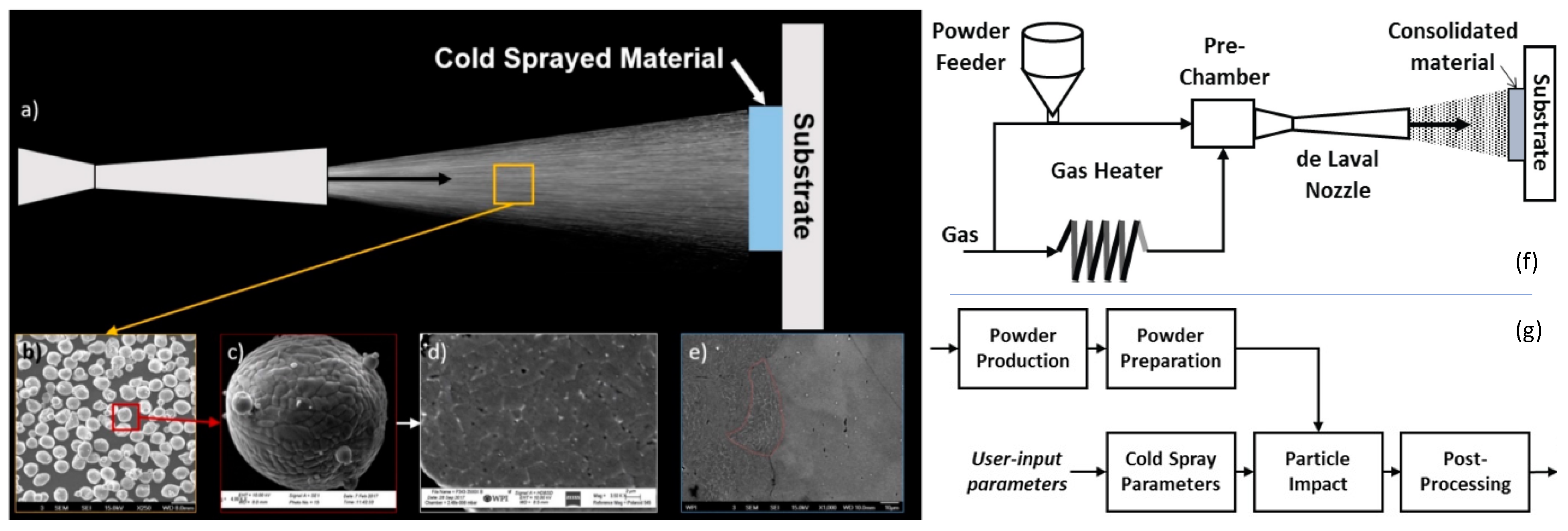
Figure 1 contextualizes the material, equipment, and process-level particularities associated with modern CSAM.
Figure 1a presents a schematic-level overview of the CS process when gas-atomized Al 6061 feedstock powder is utilized. Figure 1b presents a micrograph of the typically utilized and gas-atomized Al 6061 feedstock in CS. In addition to Figure 1b,c presents a micrograph of the external surface of a gas-atomized Al 6061 powder particle for CS, while Figure 1d presents a cross-sectional micrograph of the internal microstructure of said feedstock particulates. From the CS-processed and consolidated vantage point, Figure 1e presents the retained and refined microstructure of the same feedstock shown in Figure 1a through Figure 1d. Building upon Figure 1a,f presents a higher-level abstraction of the CS process, whereas Figure 1g illustrates how various stages of the CS process are related to one another in a through-process manner. For further details, note that Figure 1a through Figure 1e were adopted from [26], while Figure 1f,g were sourced from [27].
Recent decades have seen the transition of CS processing and CSAM from mostly governmental facilities, national laboratories, and academic institutions to the commercial and industrial sectors due to its flexibility in upscale robotics and material permutations [28,29]. In any case, advanced CS and CSAM processing development continues to emerge and evolve through unique applications by way of invoking a process–structure–property–performance perspective [30], which sometimes takes the form of a through-process methodological and experimental framework [31,32]. Consequently, the resultant materials consolidated via CS have reportedly achieved appreciable technological readiness, scientific robustness, and economic viability [33]. In turn, one of the aims of the present review was to contribute to the continued accumulation of modern findings surrounding CS and CSAM processing.

2. Methodological Matters and Preparation

Herein, generalized information is presented and reviewed before delving into the subtle details surrounding microstructural and micromechanical characterization of powder feedstock for CSAM applications, their relations to modeling efforts, and a through-process perspective. Regardless of the area of microparticulate material characterization under consideration, such as microstructural or micromechanical characterization, metallurgical sample preparation is generally involved. Thus, methodological matters directly related to said experimental domains are first presented, reviewed, and inventoried. Shared methodological and metallurgical sample preparation steps described herein are followed by additional details documented in the current manuscript concerning thermal preprocessing of CSAM feedstock, CS powder feedstock flowability analysis, and other aspects and modalities worth noting. Finally, details surrounding devices, manufacturers, and parameters (or means of determining said parameters) are reviewed.

2.1. Sample Preparation and Powder Size Analysis

The Cote Research Laboratory (Worcester, MA, USA) characterized particle size distributions and morphologies using a Microtrac FlowSync system (Microtrac Retsch GmbH, Haan/Duesseldorf, Germany). Powder and CSAM samples were mounted in a phenolic resin using a Buehler Simplimet 4000 (Lake Bluff, IL, USA) compression mounting system for scanning electron microscopy (SEM) and similar types of characterization. A Buehler Ecomet 300 automatic polisher was used for grinding and polishing until reaching a final 0.05 μm colloidal silica suspension. Powder samples were prepared using argon gas in a JEOL IB-19530CP cross-section polisher (Tokyo, Japan) to improve SEM microscopy. Ar ion beam milling was performed at 8 kV for 3 h with an intermittent polishing procedure when alloyed Al microparticulate feedstock was explicitly considered.

2.2. On Microstructural Assessment

SEM micrographs were obtained of powder and CSAM microstructures using a Zeiss EVO MA10 (Carl Zeiss AG, Oberkochen, Germany). A Bruker X Flash Energy-Dispersive Spectroscopy (EDS) Detector 630M (Bruker Nano GmbH, Berlin, Germany) was used for chemical mapping. Image analysis software, such as Olympus Stream, was used to analyze secondary phase fractions and grain size of SEM micrographs using contrast thresholding previously mentioned elsewhere [19]. X-ray diffraction (XRD) can be conducted on powder feedstock and CSAM material consolidations by way of an Empyrean X-ray Diffractometer (Malvern Panalytical Ltd., Almelo, Overijssel, The Netherlands), a Cu-Ka radiation source, and a Ni filter (as well as other filter types depending on the materials tested and the material tendency to fluoresce when exposed to X-rays). Data analysis of XRD spectra was completed using HighScore Plus.

2.3. On Micromechanical Assessment

Nanoindentation was primarily performed using an iMicro Pro from the KLA Corporation (KLA Instruments, Milpitas, CA, USA) on powder particles that were metallographically prepared. This instrument used an InForce 1000 mN actuator with a diamond Berkovich tip from Micro Star Technologies Inc. (Huntsville, TX, USA) using the InView Software program (Version 19.2.24). Nanoindentation hardness measurements were reported at average depths between 195 and 205 nm using the dynamic CSM method (or some depth regime slightly larger than 200 nm when particles were sufficiently large). A fused silica reference standard was used to measure the contact area function and the frame stiffness via load–depth data. Thermal drift, pile-up, and creep-related phenomena were corrected during testing. Beyond the Berkovich indenter tip and InForce 1000 mN actuator, InForce 50 mN actuators were also utilized within the iMicro system, as well as an in situ NanoFlip nanoindentation test system. Moreover, cono-spherical and flat-punch diamond indenter tips were utilized and sourced from Synton MDP. A static and quasistatic nanoindenter from Keysight G200, which is now incorporated under the umbrella of KLA Instruments, was also employed. Again, the citation provides further information and much greater detail.
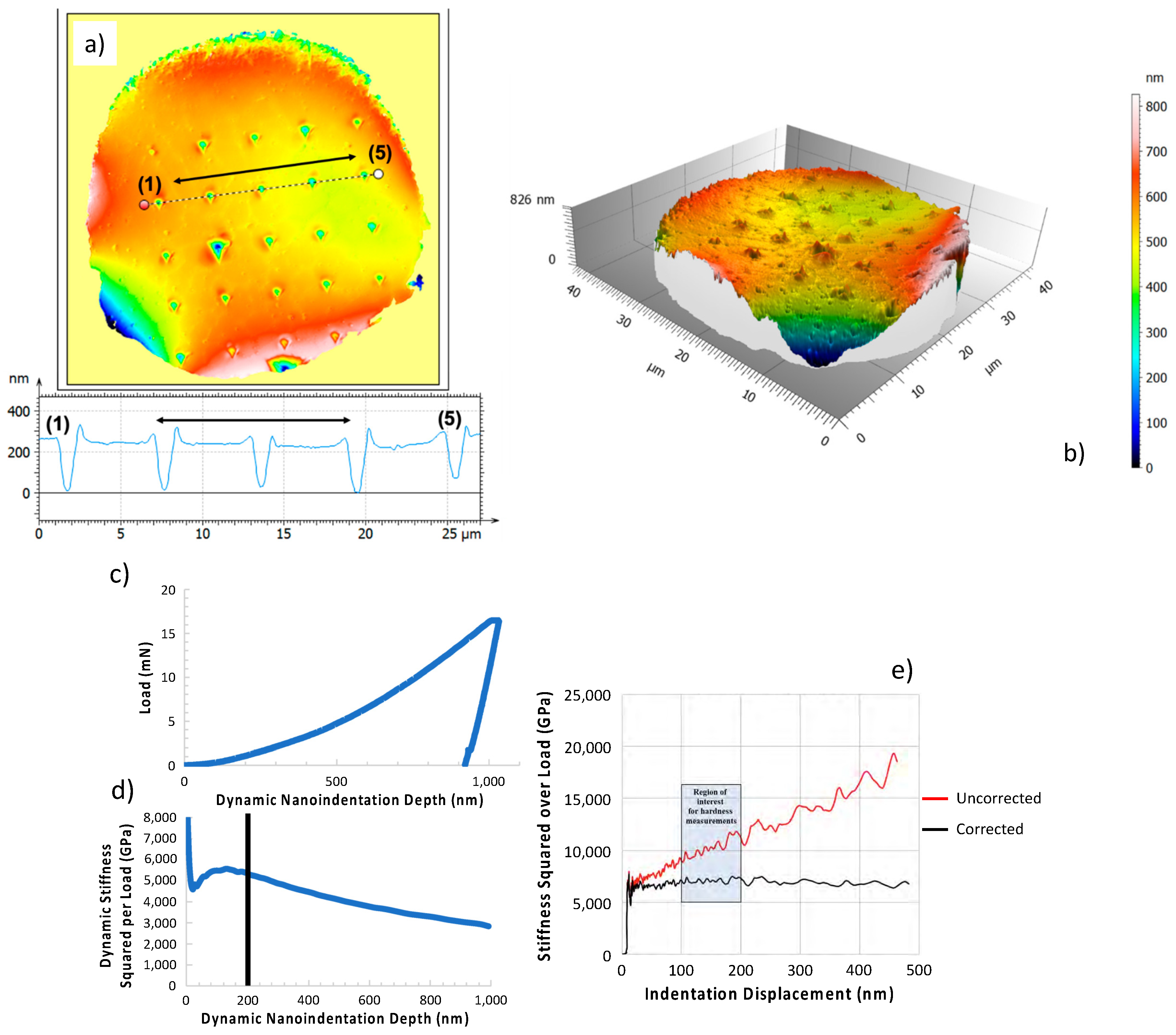
A DiaMet Hardness Tester from Buehler (Lake Bluff, IL, USA) was used for microhardness testing. A Vickers indenter tip and an applied force of 0.1 kgf were used to collect microhardness data. Due to similarities in the tip contact area for Vickers and Berkovich and similar strains during indentation testing, depth-dependent nanoindentation hardness values were converted to a Vickers Hardness Number (VHN) for comparison with the microhardness responses associated with CSAM counterparts, as needed. For comparison, note that for nanoindentation, the load required to achieve an indentation depth of 250 nm during testing of gas-atomized Al alloyed powders studied here was only 0.000254929 kgf versus the 0.1 kgf during microindentation, pointing out that powder cannot be adequately evaluated via microindentation testing. In turn, such pedogeological and methodological matters and nuanced nature prompted the formation of Figure 2, which substantiates the inability to measure the mounting material independent hardness of a particle via a Vickers indenter. Figure 2 also highlights the nature of indentation-induced deformation accumulation when Berkovich nanoindenter tips are loaded onto microparticulate feedstock for CSAM processing.
In addition, Figure 2a,b presents the pile-up associated with a nanoindented, gas-atomized Al 6061 CSAM feedstock microparticle, as measured via the application of confocal microscopy [10]. Figure 2c presents a dynamic nanoindentation load–depth curve for another Al 6061 CSAM feedstock microparticle [10]. Figure 2d presents the dynamic stiffness squared per load versus nanoindentation depth curve for a set of the same gas-atomized Al 6061 CSAM feedstock microparticles presented as part of Figure 2c. The superimposed black line associated with the curve plotted in Figure 2d highlights how such a curve can be utilized to identify the proximal limit of mounting matrix material free indentation depth when a powder particle is embedded within a relatively more compliant matrix and subjected to nanoindentation loading [10]. Figure 2e presents data similar to Figure 2c,d; however, rather than identifying a limit for indentation testing, the authors explored the use of a corrective measure for data influenced by mounting material properties [10,34].
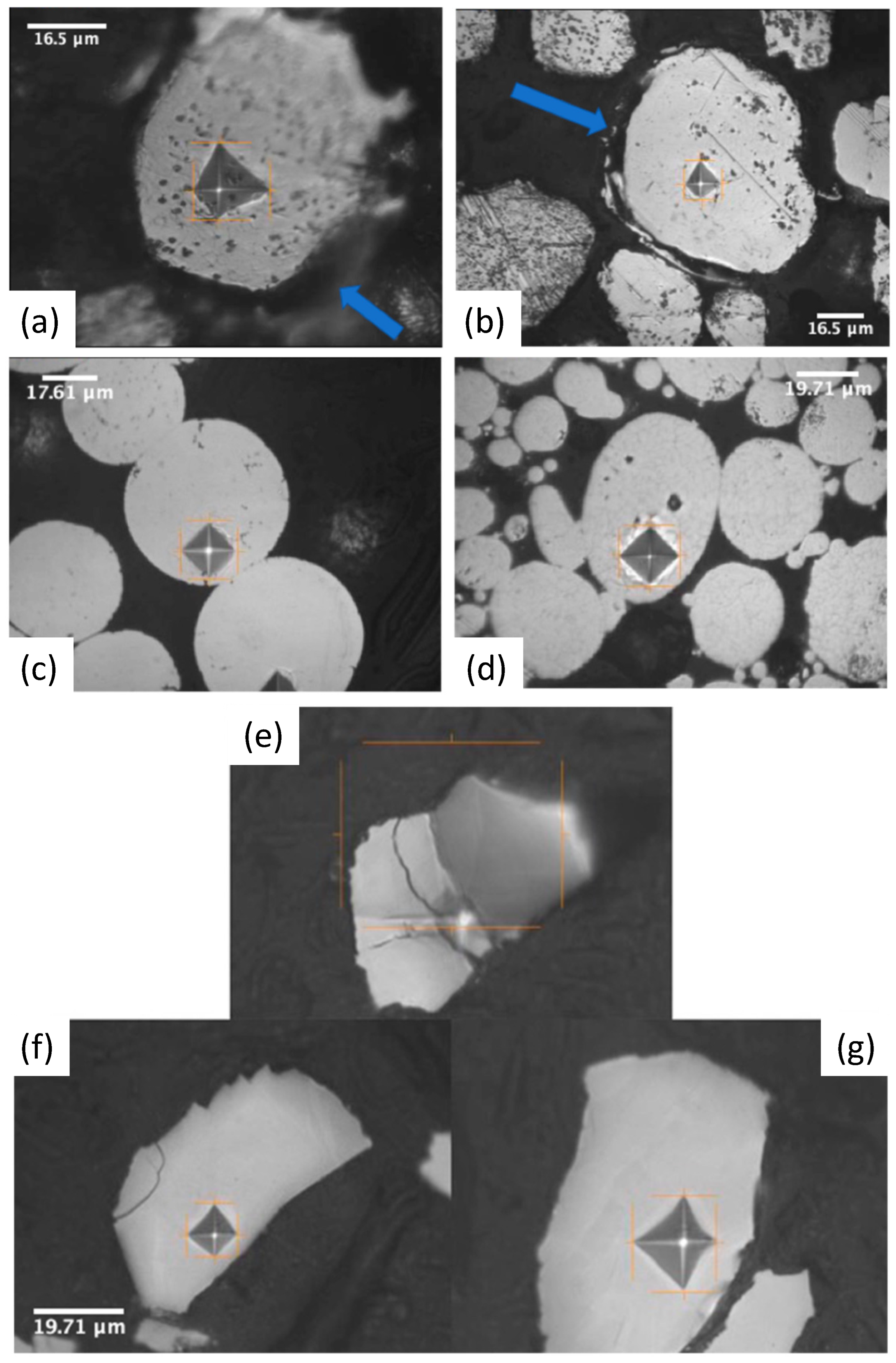
Figure 3a demonstrates that microindentation or microhardness testing via Vickers indentation, at a load of just 0.01 kgf and applied to an embedded Al alloy CSAM feedstock powder, results in particle decohesion and immersion into the mounting material [10]. Figure 3b presents powder immersion into the mounting material following decohesion from the matrix during Vickers indentation. Figure 3c–g demonstrates the effects of microindentation for mechanical evaluation of powder particles embedded in mounting media, such as indentation sizes exceeding plastic deformation zone limits for measuring matrix-free powder particle properties [10].

3. Microstructural Characterization

Microstructural characterization of microparticulate feedstock for CSAM processing and advanced materials processing is achieved via SEM, transmission electron microscopy (TEM), energy dispersive X-ray spectroscopy (EDS), electron backscatter diffraction (EBSD), optical microscopy, confocal microscopy, XRD, image analysis, etc. However, particle and powder microscopy and analysis depend on the microstructural features of interest of a given CSAM researcher, powder metallurgist, or materials engineer and scientist. For example, in [35,36], focused ion beam milling of entire spherical powder particles was pursued for polycrystallinity inspection and quantification in terms of internal grain sizes and grain orientations relative to their nearest neighbors. While Cu was focused on in [35,36], a similar analysis was performed for gas-atomized Al 6061 spherical powder particles; however, in [10,26], Ar ion beam cross-sectional milling-based polishing and sample preparation of similarly prepared feedstock particulates, which is in contrast with the FIB-based procedure invoked. While both approaches were found to be well suited for EBSD analysis via SEM analysis and characterization, the economics of cross-sectional polishing of many particles at a time relative to the cost-intensive nature of FIB-based sample preparation, as well as the passive nature of Ar ion beam cross-sectional polishing, have led to more significant consideration and use by the present authors for CSAM feedstock microscopy needs. Beyond the difference stemming from cross-sectional ion beam-based metallurgical particulate specimen preparation (and the tendencies of the present authors towards cross-sectional ion beam milling over FIB-based polishing), Figure 4, Figure 5 and Figure 6 present various uses of microstructural analysis for CSAM feedstock quantification for CSAM processing.
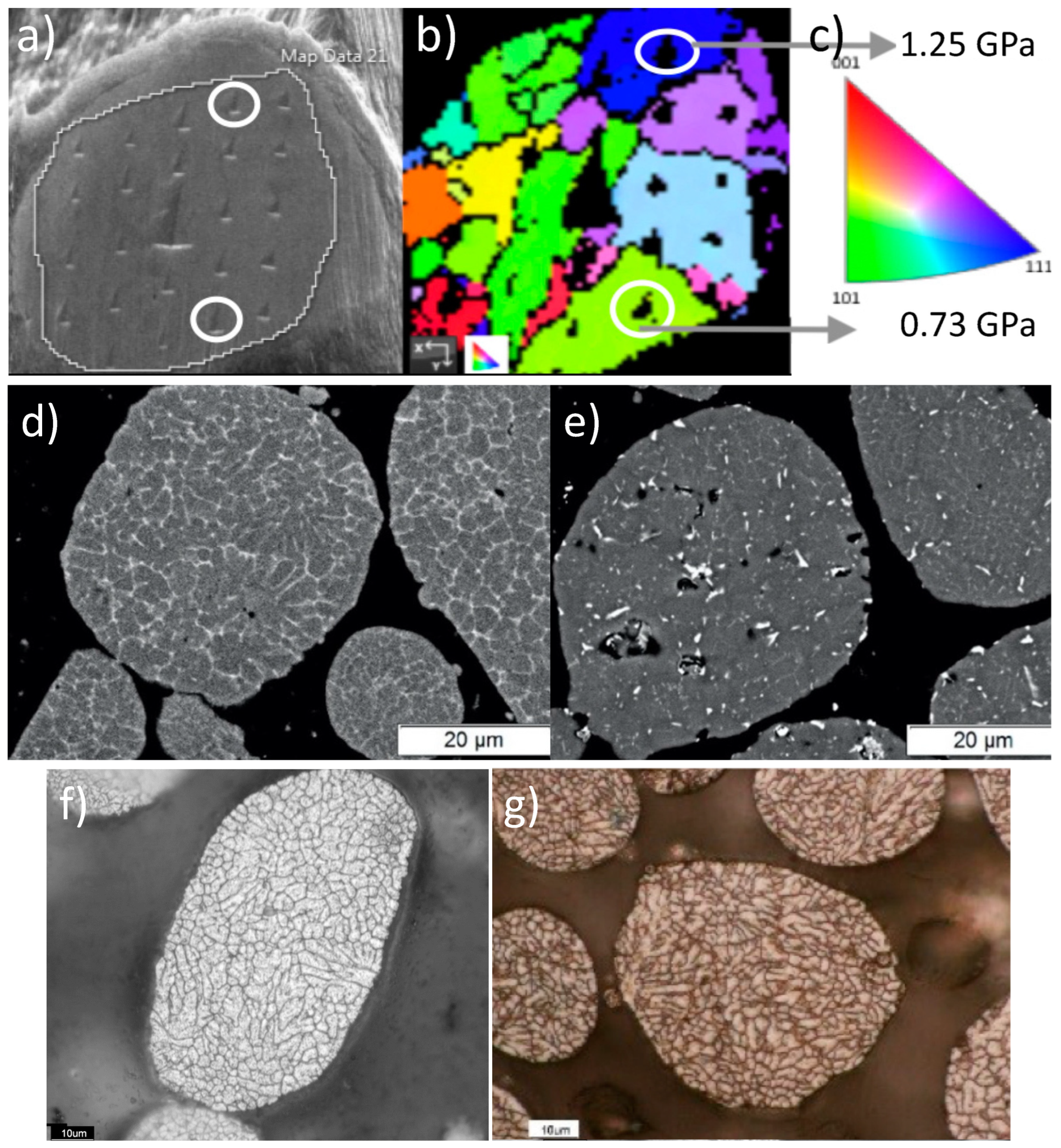
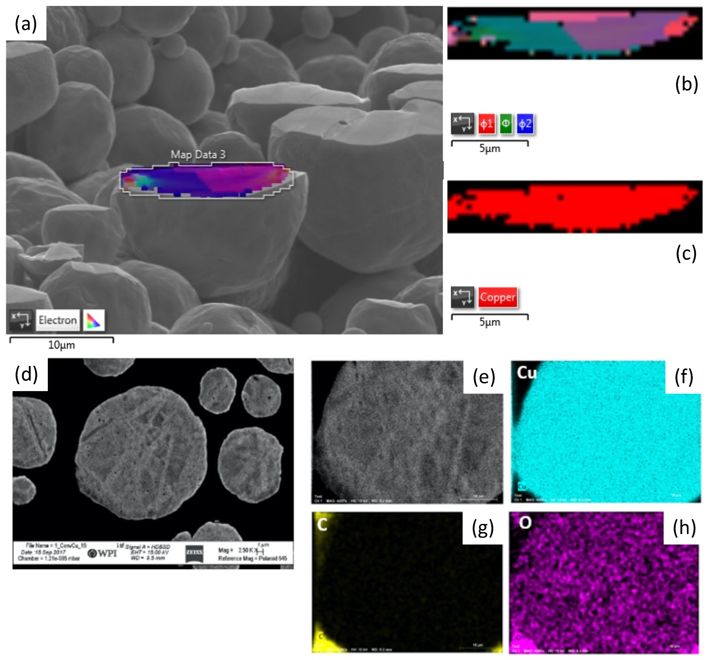
More specifically, Figure 4a presents an SEM micrograph of a powder particle after nanoindentation, Figure 4b presents an electron backscatter diffraction (EBSD) image using inverse pole figure (IPF) direction X orientation, and Figure 4c presents hardness of indents and a color map of Miller indices [10]. Electron micrographs comparing the microstructures of as-atomized Figure 4d and thermally treated gas-atomized powder are shown in Figure 4e via SEM for Al 7075, as noted by Sousa et al. in [13]. As noted by Handel, Figure 4f presents gas-atomized Al 7075, which was etched for 40 s at 70 °C via an aqueous nitric acid solution in [37]. On the other hand, Figure 4g presents the chemically etched optical micrographs for the as-atomized Al 7075 system microparticulate CSAM feedstock. The scale for the chemically etched and gas-atomized Al 7075 micrograph was 10 μm [13].
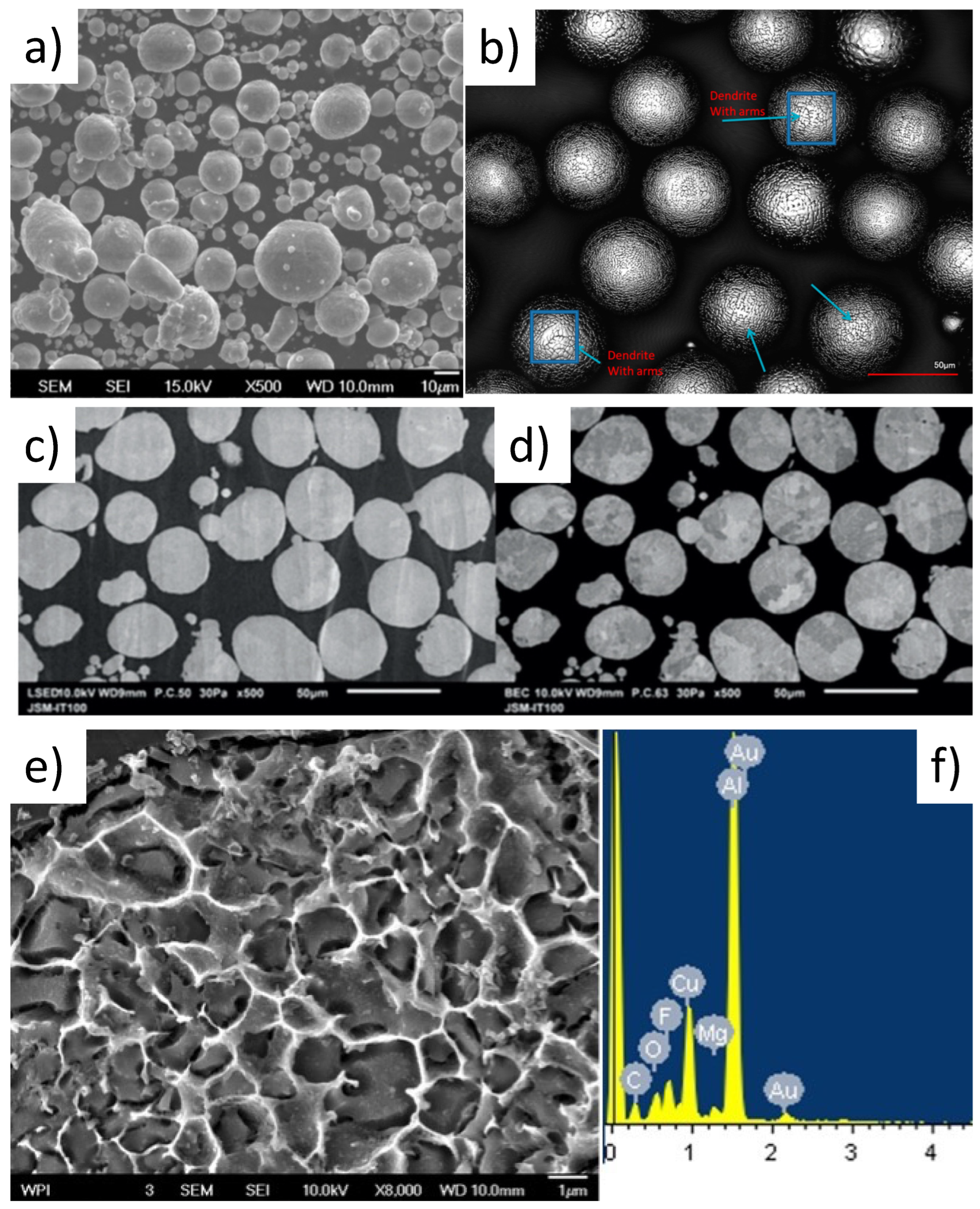
Figure 5a–c presents EBSD analysis of gas-atomized and commercially pure Cu particulate feedstock after FIB milling. Figure 5d–h presents EDS analysis of GA Cu powder. Additional details surrounding Figure 5 can be found in [36].
Also noted by Handel in 2015, Figure 6e,f present “[gas-atomized] Al 2024 [powder] etched for 60 s with 0.5% aqueous HF acid and EDS composition results” [37]. Figure 6a captures SEM micrographs of the relevant gas-atomized Al 6061 powder in the as-received condition [10]. Figure 6b presents a laser scanning confocal micrograph of rapidly solidified Al 5056 powder, thus revealing their dendritic solidification microstructures [10]. Finally, Figure 6c,d depict secondary electron and backscatter electron SEM micrographs following cross-sectional Ar ion beam polishing [10].

4. Micromechanical Characterization

Regarding nanomechanical and micromechanical characterization of the respective feedstock systems considered during the present review, much attention was paid to the range of indentation penetration contact depths that can be considered before surpassing the limit of the particle-dominated deformation displacement upper bound. Avoidance of said indentation depth limits, as a function of the hemispherical constituent’s radius embedded in the relatively softer mounting material matrix, ensures that mounting material matrix-dominated deformation is avoided, and only particulate hardness and modulus values are recorded and then analyzed. Accordingly, 
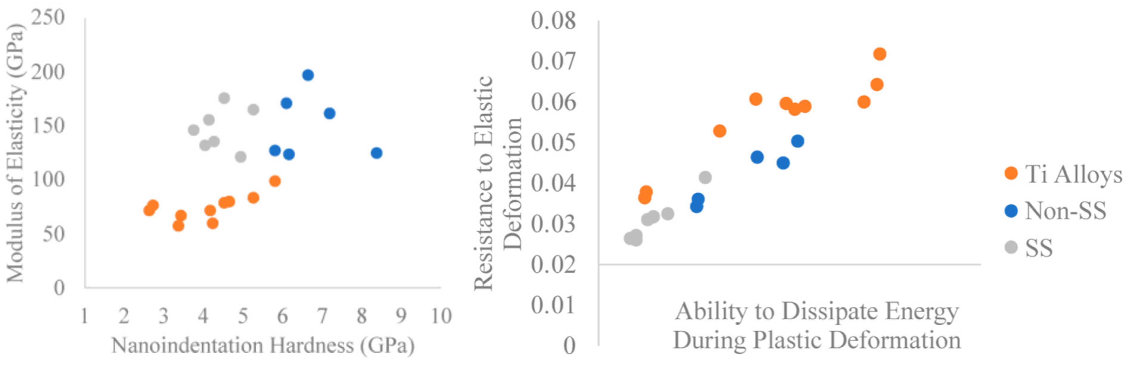
Figure 7 presents a micromechanical assessment of CSAM feedstock powder, in part, and the utility of nanoindentation applied to microparticulate material when said particle-dominated deformation displacement limitations are observed.
Stated otherwise, Figure 7 presents the modulus of elasticity versus hardness of the Ti alloy and steel gas-atomized powders [10]. On the other hand, Figure 7 also plots the resistance to elastic deformation and the ability to dissipate energy during plastic deformation of the same powder [10]. In turn, relationships between critical velocity, resistance to plastic deformation, and moduli can be deduced per Figure 7.
On the other hand, comparisons of micromechanical properties of consolidated CS-processed specimens, recorded at an equivalent nanoindentation penetration depth, enable insights surrounding the degree of severe plastic deformation incurred as a function of CS processing parameters employed (as shown in Figure 8). 
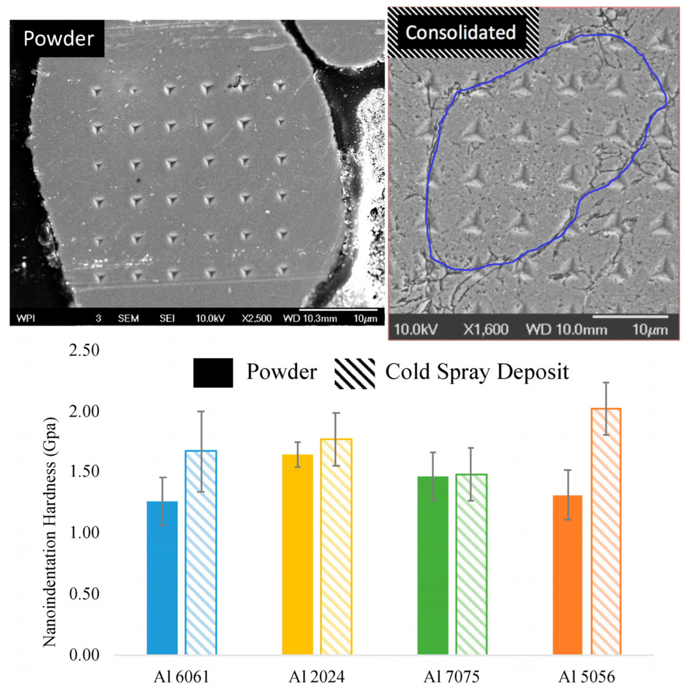
Figure 8 presents an SEM image of a grid of hardness indents on a single Al 6061 powder particle [10]. Figure 8 also presents an SEM image of a grid of hardness indents on the spray direction face of a consolidated Al 6061 coating. The coating was etched with 0.5% hydrofluoric acid solution for 5 s to reveal particle boundaries. A blue line highlights one particle boundary. Figure 8 also depicts a graph of the average hardness for Al 6061, Al 2024, Al 7075, and Al 5056. The solid bar shows the average hardness for all powder sizes, while the dashed bar represents the consolidated sample [10].
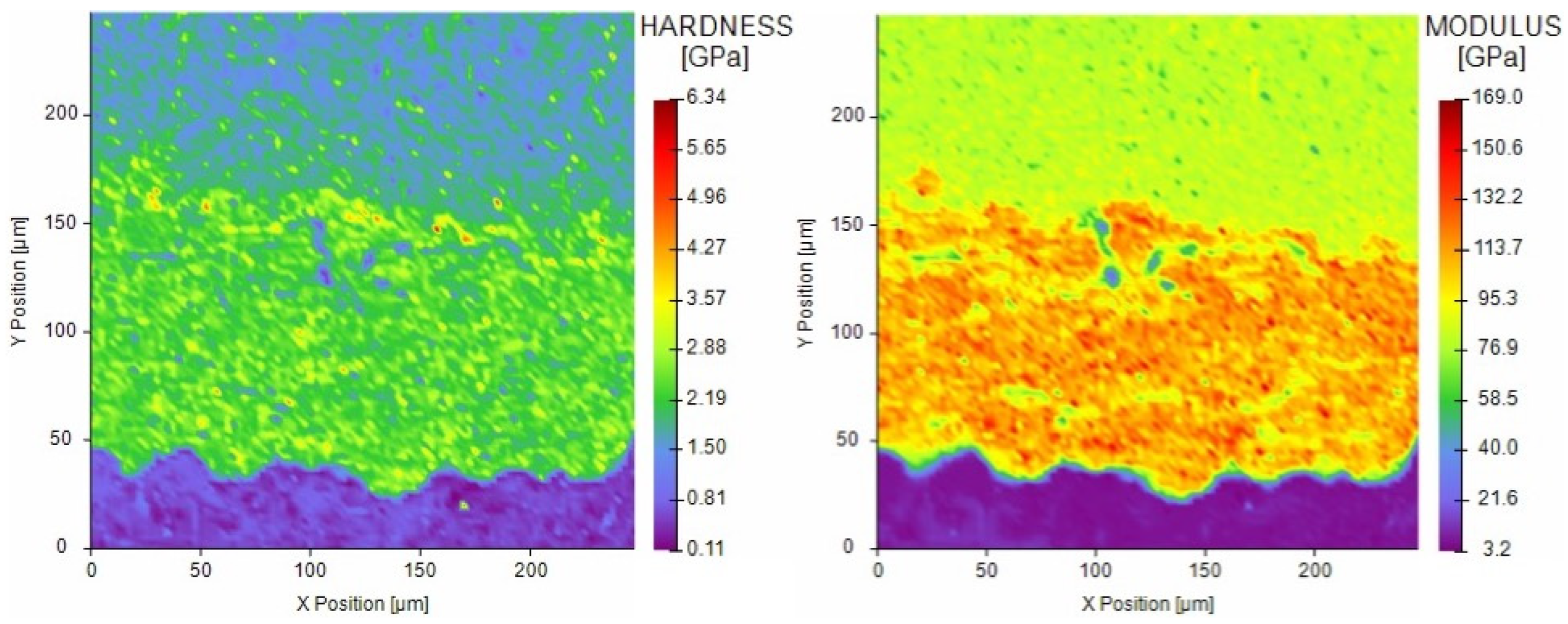
Nanomechanical mapping methods to assess the site-specific distribution of properties such as hardness and modulus of elasticity for CSAM-processed consolidation-substrate properties are presented in Figure 9. Figure 9 concurrently presents nanomechanical mapping methods to assess the site-specific distribution of properties such as hardness and modulus of elasticity for CSAM-processed consolidation–substrate properties.
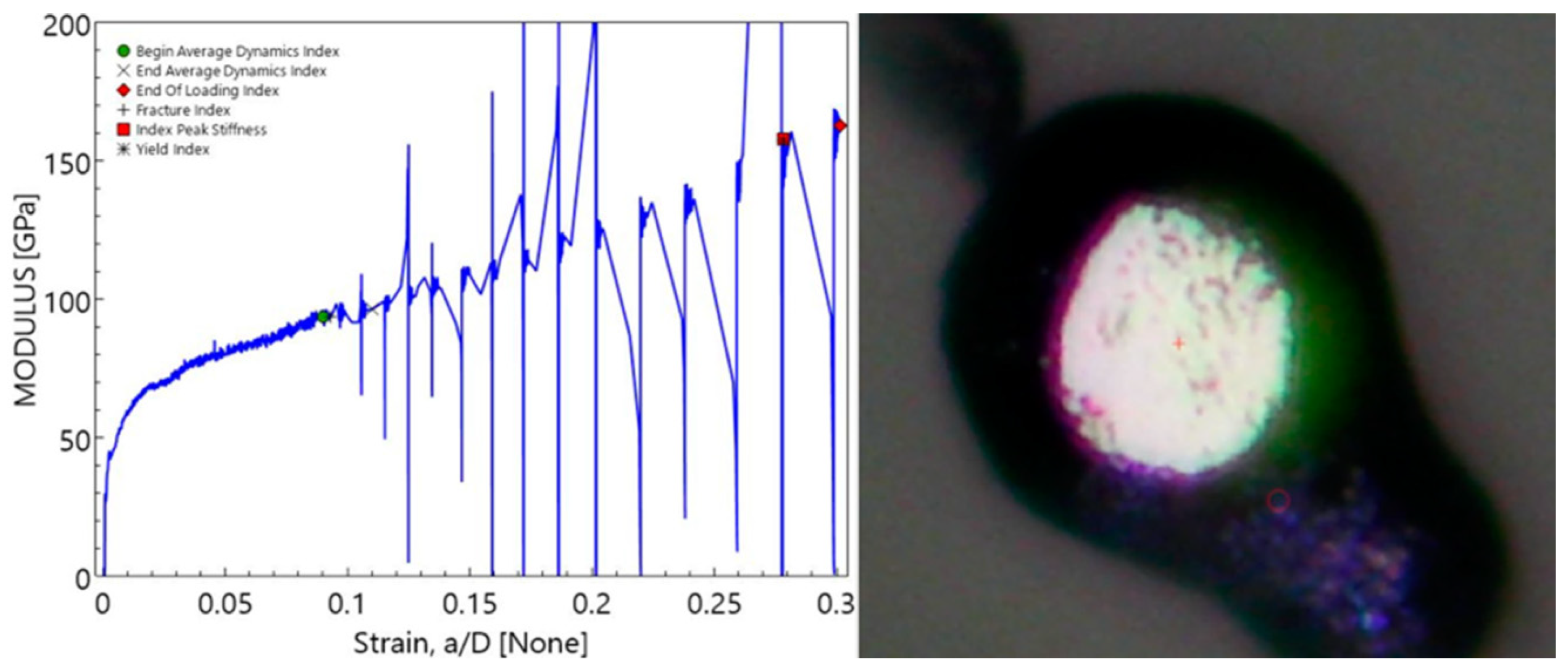
Nanoindentation testing is not the only means of achieving powder particle mechanical properties. For example, as shown in Figure 10, microparticulate compression testing using a flat punch-equipped nanoindenter enables global, rather than local, micromechanical properties to be assessed as a function of compressive strain. Stated otherwise, Figure 10 presents microparticulate compression testing using a flat punch equipped with nanoindenter-based micromechanical properties to be assessed as a compressive strain for Al 5056 feedstock.

5. Relation to Computational Modeling

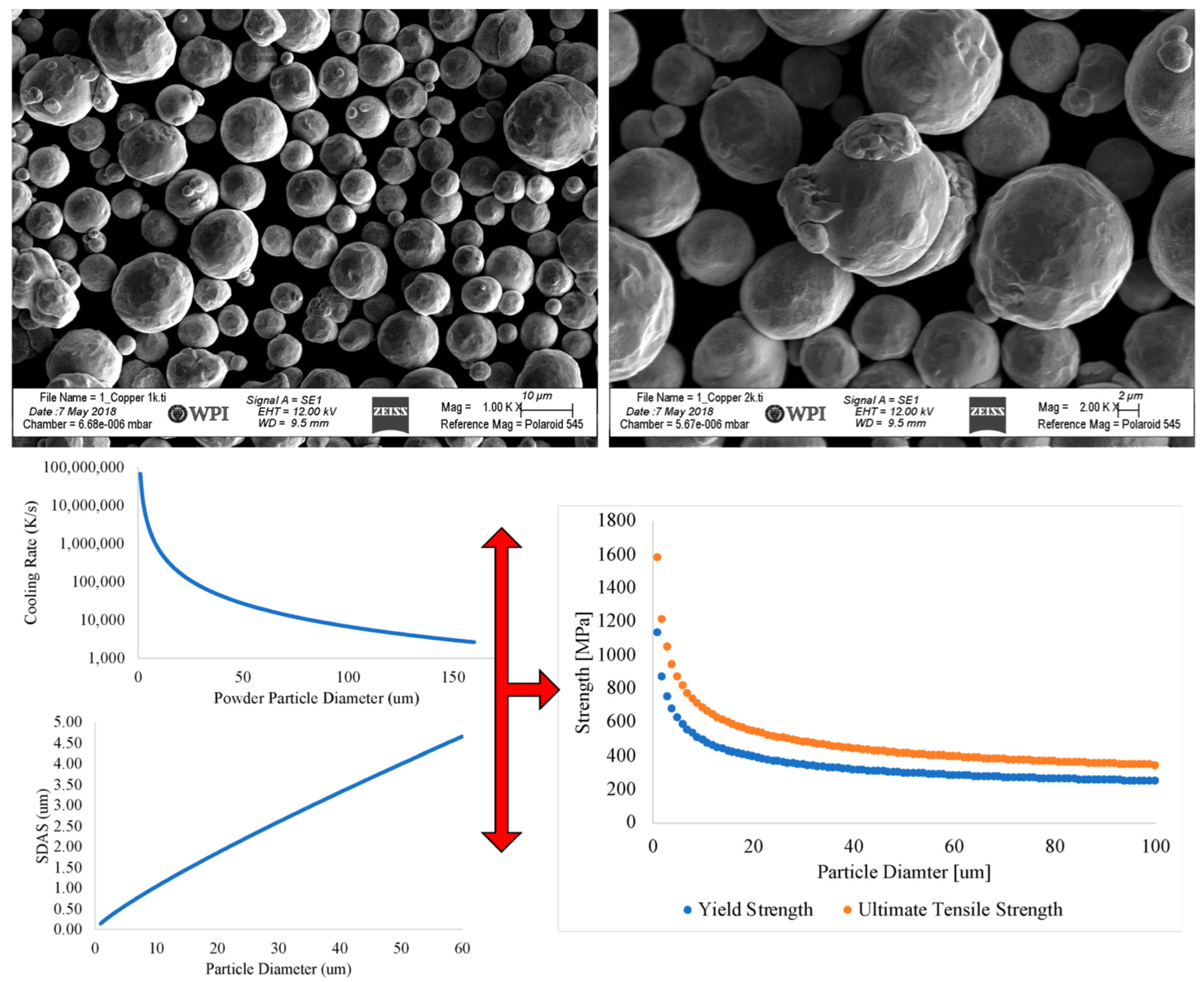
The gas-atomized powder is frequently used as the feedstock material for CS. During gas atomization, molten metal is atomized using a gas stream, where it solidifies and is collected as powder. Due to the rapid rates of solidification, equiaxed, dendritic, and cellular microstructures can be created, which can contain the segregation of solute elements varying with powder composition and gas atomization parameters. For example, Al 6061 is effectively free of elemental segregation in the inertly gas-atomized condition, whereas inertly gas-atomized Al 5056 has been found to house chemical segregation in regions near grain boundaries. In addition, the powder particles’ size and shape are influenced by gas atomization processing and alloy composition.
Moreover, powder particles are primarily spherical for aluminum alloys, yielding a broad distribution when produced via gas atomization. Other relations to computational modeling extend beyond alloyed Al or rapidly solidification microstructures alone, as highlighted in Figure 11 for pure copper feedstock. Figure 11 presents an SEM micrograph of an as-atomized pure copper microparticulate feedstock for CSAM. For the gas-atomized powder depicted in Figure 11, Figure 11 concurrently presents the cooling rate as a function of microparticulate size, the secondary dendrite arm spacing as a function of particle diameter and, therefore, the cooling rate, and the estimated yield and ultimate tensile strength of the powder from the solidification models.
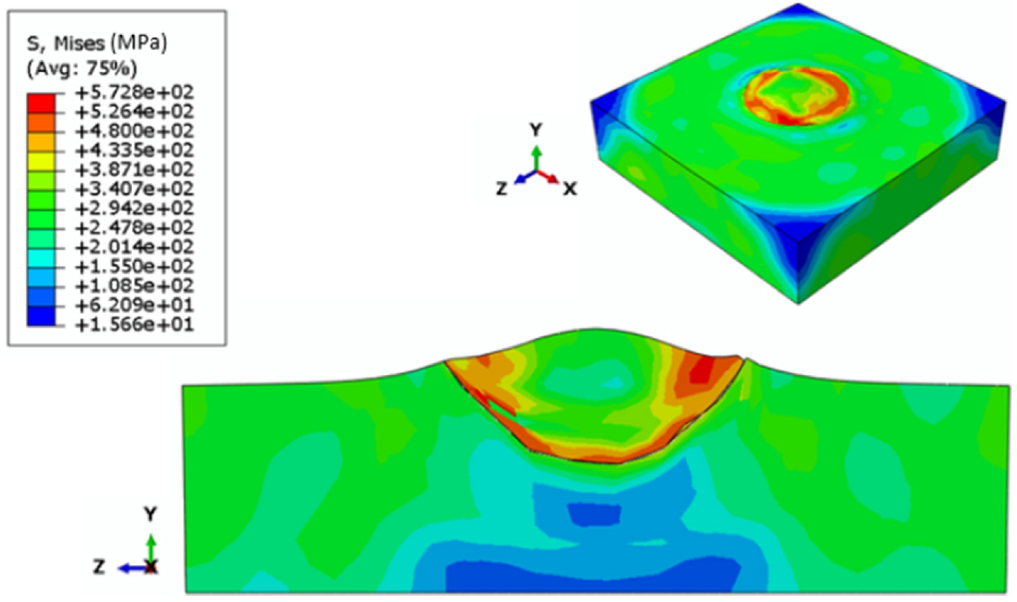
CS processing-induced impact phenomena for a copper powder particle from the batch of feedstock were modeled and captured in Figure 12. In other words, Figure 12 presents the Johnson–Cook von Mises flow stress profile for said copper microparticulate CSAM feedstock impacting an Al 6061-T6 wrought target substrate or build plate [35].
Figure 13, Figure 14 and 
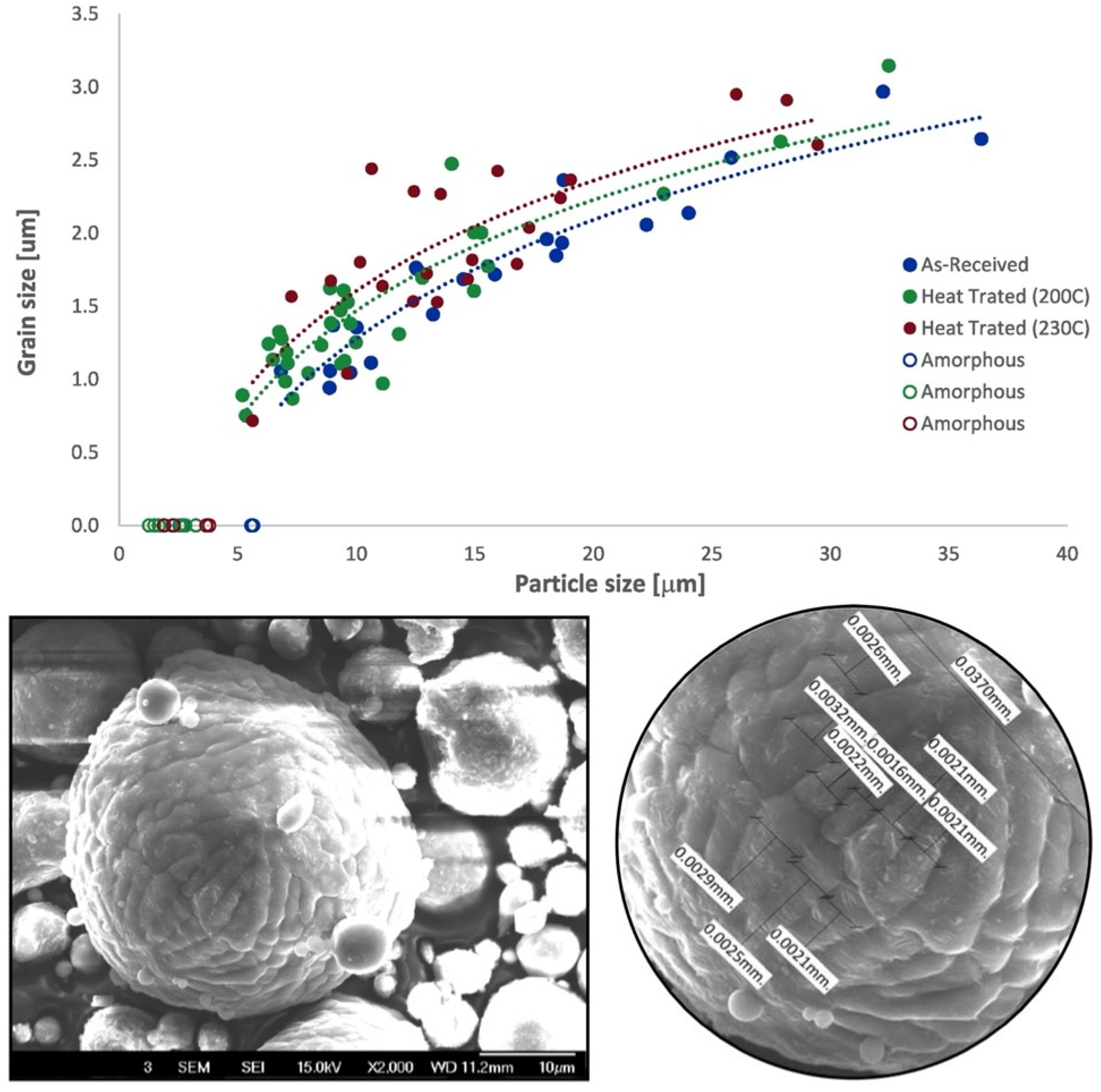
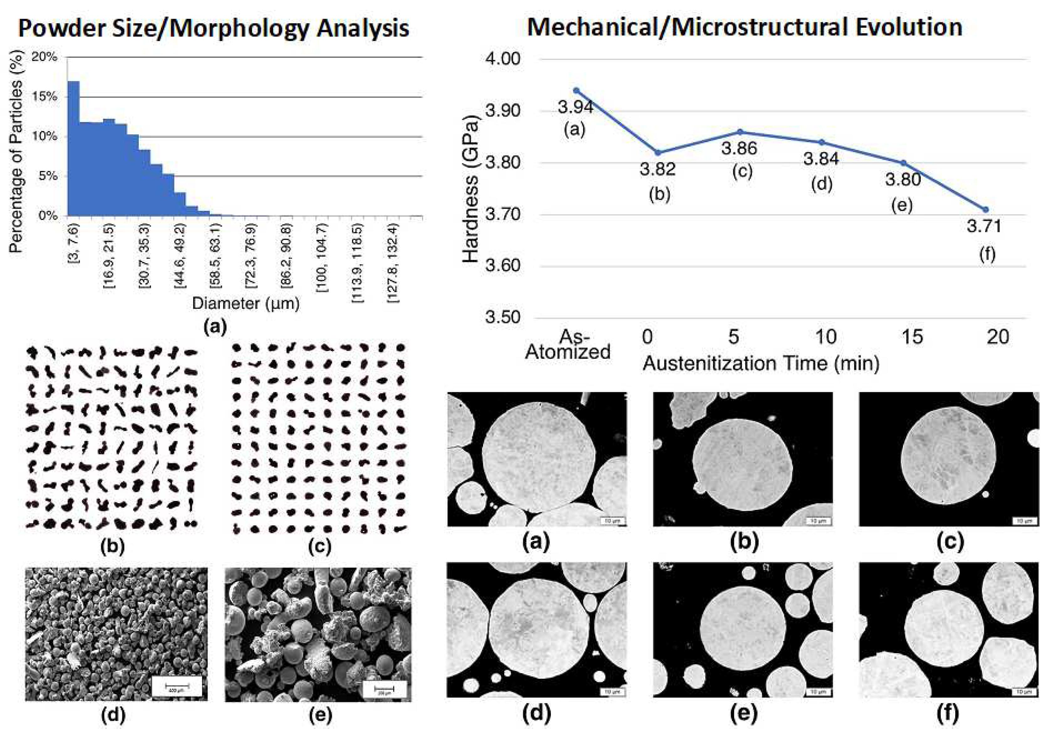
Figure 15 present coupled experimental–computational analyses for alloyed Al CS feedstock as a function of microparticulate size and thermally pre-processed condition relative to the as-atomized condition. As for gas-atomized Al 6061 powder, Figure 13 presents SEM micrographs of the as-atomized feedstock and an example of the measured secondary dendrite arm spacing used to substantiate the modeled grain size versus particle size as a function of cooling rate and preprocessed condition [10].
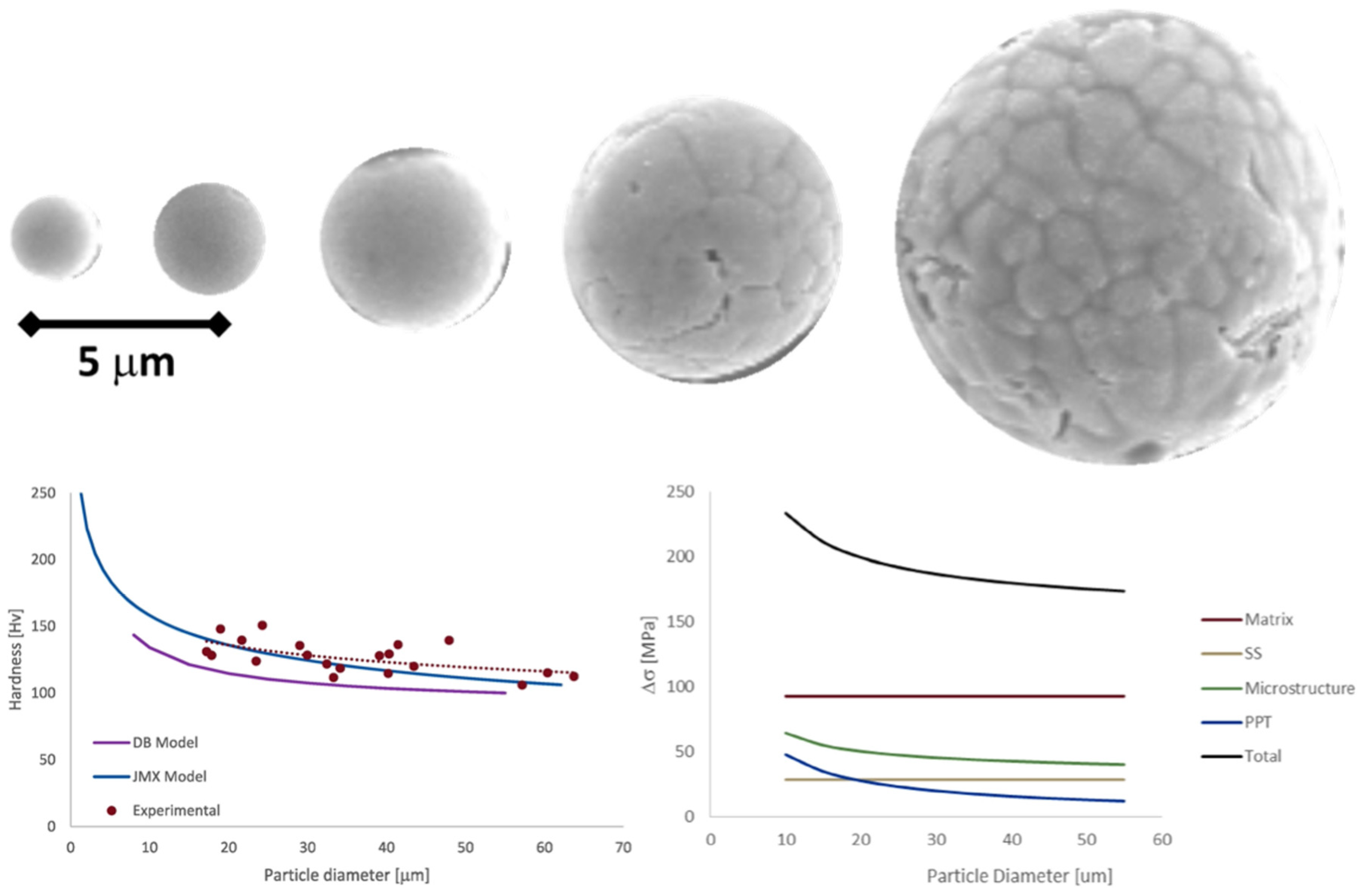
Figure 14 presents SEM characterization of lightly etched, gas-atomized Al 6061 powder particles for CSAM and CS processing as a function of size and, therefore, cooling rate. In addition, Figure 14 presents the experimentally measured particulate hardness as a function of size versus modeled hardness as a function of powder particle diameter for gas-atomized Al 6061.
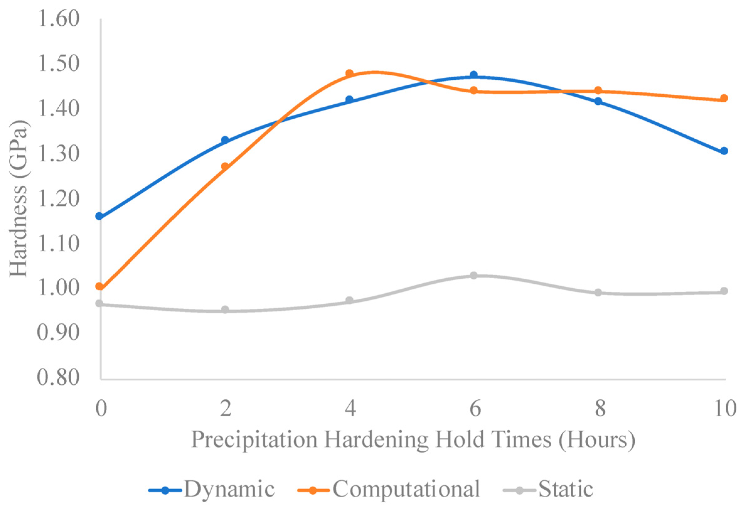
Figure 15 presents the dynamically measured, statically measured, and computationally assessed particulate hardness obtained for Al 6061 feedstock (as a function of thermal pre-processing hold times). In contrast, Figure 14 also presents the contributions to particulate strength from secondary phases, grain size, solid solution strengthening, and so on for the as-atomized condition. For more information, see [10,27].
In addition to the hybrid experimental–computational assessment for CSAM feedstock powder-level property determination presented above, Figure 16 and 
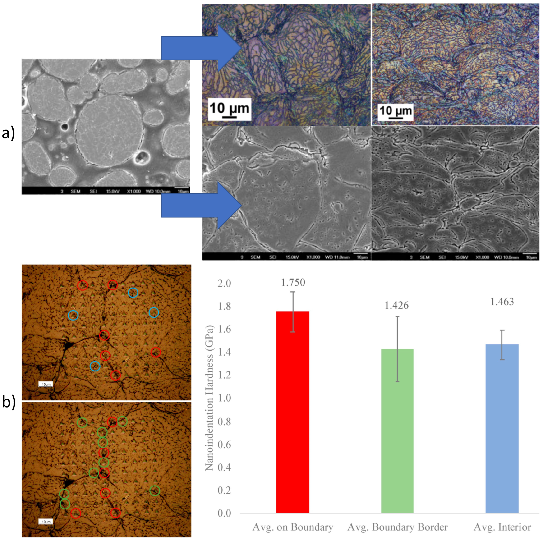
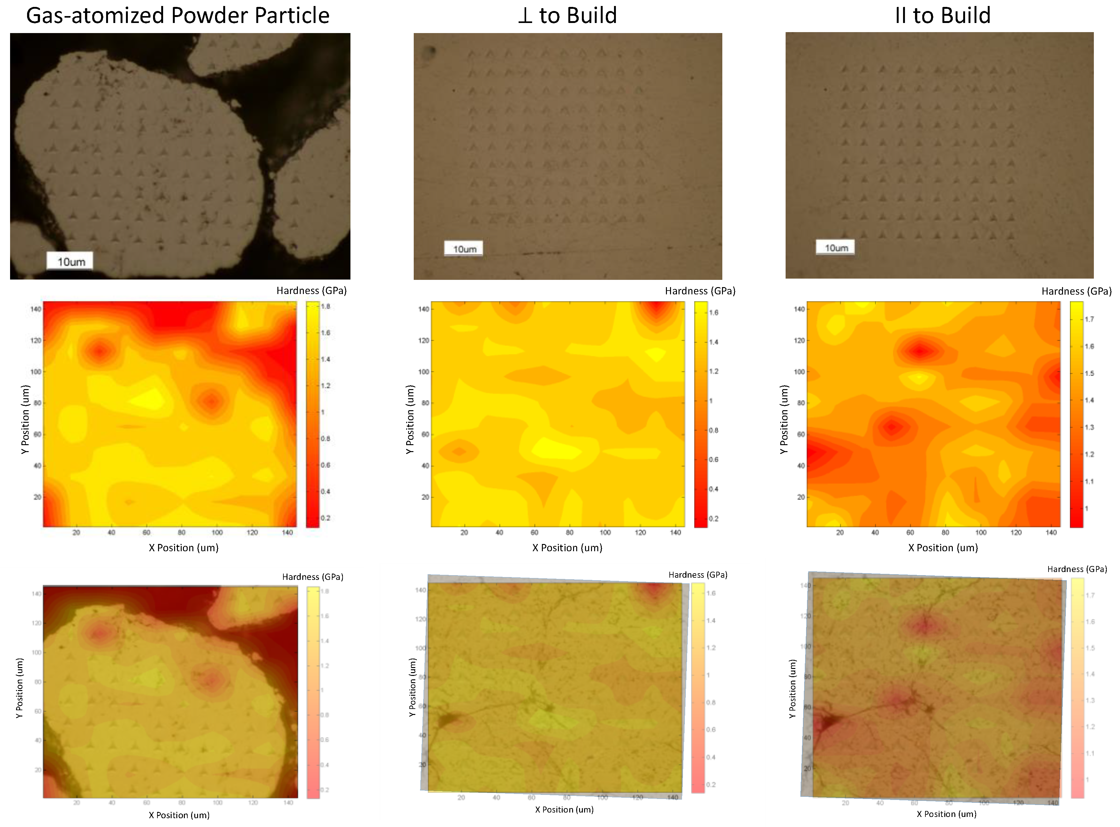
Figure 17 demonstrate the utility of through-process consideration applied to CS processing for gas-atomized Al 6061. That said, through-process utility is also presented in terms of gas-atomized pure copper and thermally pre-processed and gas-atomized stainless-steel feedstock. More to the point, Figure 16a presents etched particulate and consolidated material microstructures as a function of orientation relative to the direction of supersonic deposition during processing. In addition to microstructural analysis, site-specific micromechanical properties of a gas-atomized Al 6061 particle and the corresponding consolidation procured are also presented in Figure 16b [10].
Figure 18 and Figure 19 shows a through-process integrated analysis of single copper particle deposits and the respective multi-layer consolidations achieved, respectively [35].
Figure 20 presents how thermal pre-processing hold times of gas-atomized feedstock can be controlled based on the diffusion kinetics of stainless-steel gas-atomized powder at the micron scale through dynamic nanoindentation testing for optimization and tunability of consolidated CSAM component performance [6].

6. From Powder to Splat to Consolidation

As mentioned above, the CS through-process model developed initially in [31] and after that, built upon by others as part of [27,40,41], serves as a means of high-throughput computational evaluation of varied processing parameters for a given application. In so far as particle–substrate and particle–layer impacts are concerned within a through-process framework and approach to CSAM, both Johnson–Cook and Preston–Tonks–Wallace plasticity models have been incorporated for in silico evaluation of how impact-induced strain, stress, and temperature distributions evolve throughout the microparticulate deposits for a given combination of processing parameters. Still, inputs to either model implemented for severe plastic deformation mechanics and analysis require powder-specific properties to be assumed or input directly into the governing formulations underpinning a respective model to capture material-dependent evolution brought about by supersonic impact processing. Noted above, the Johnson–Cook model requires the yield strength of the material to be defined for a given feedstock system. While many researchers have elected to assume that bulk mechanical properties hold in place of particle-specific mechanical behavior (an assumption recently shown to be detrimental and improper for gas-atomized, rapidly solidified, Al alloy feedstock in [13]), recent work has computationally demonstrated the need for feedstock-specific model inputs when finite element analysis is invoked. Considering such implications for through-process modeling of CSAM processing, Figure 21 and Figure 22 demonstrate an integrated experimental approach previously explored in conjunction with FEM formulation for single microparticle impact phenomena.
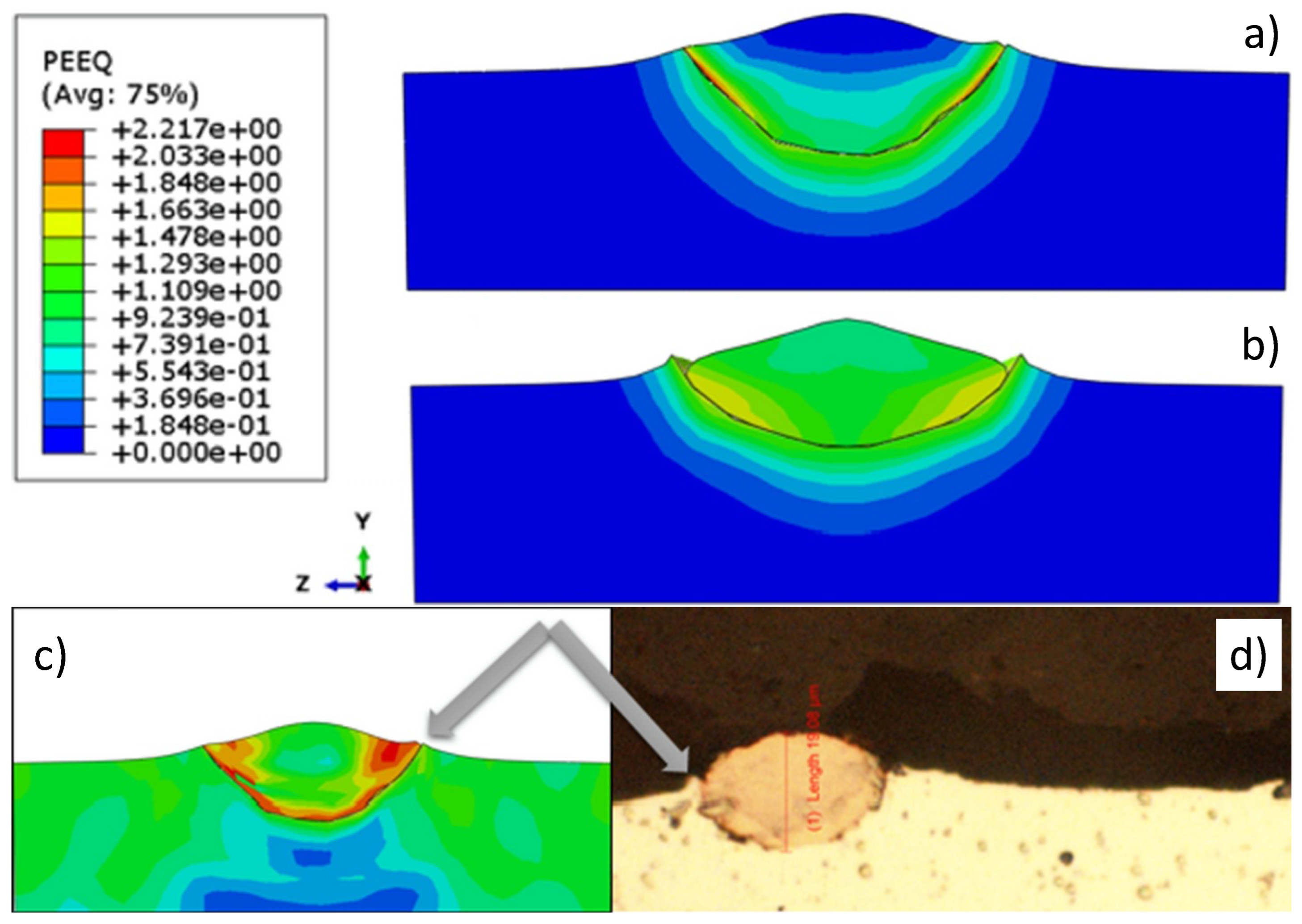
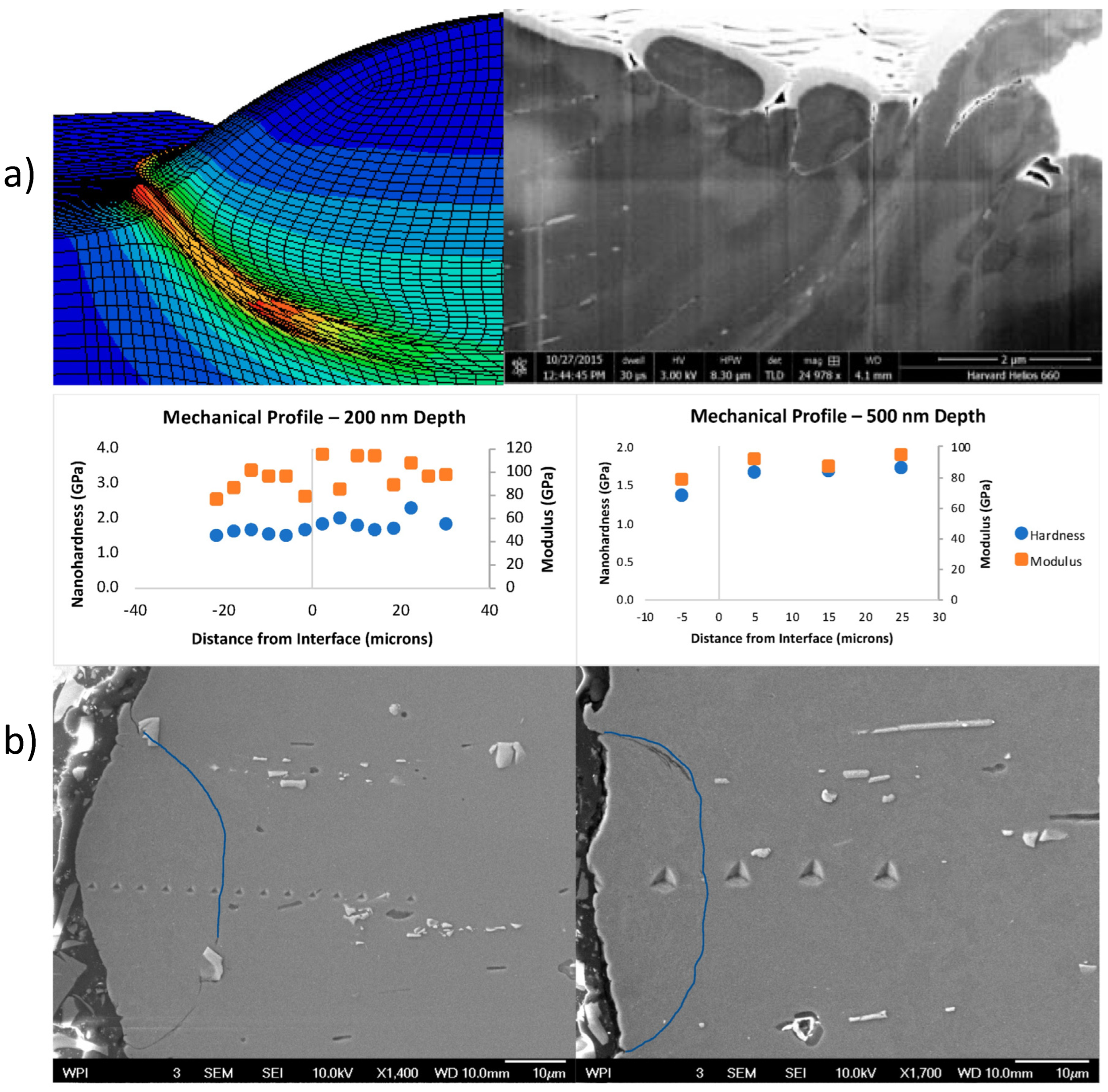
Single powder particle finite element analysis of the plastic equivalent strain state achieved for the high strain rate impact of a gas-atomized Al 6061 microparticle upon a target substrate is presented in Figure 21a. A microstructurally characterized cross-section of a comparable Al 6061 particle–substrate deposit was also presented to complement the computational analysis [10]. In addition to Figure 21a,b presents nanoindentation-based measurements of hardness and modulus of elasticity as functions of depth and location across the particle–substrate deposit system. As noted in [10], the “negative values [found in Figure 21b] are within the particle, the (0,y) point is the particle/substrate interface, and positive position values are within the substrate material.”
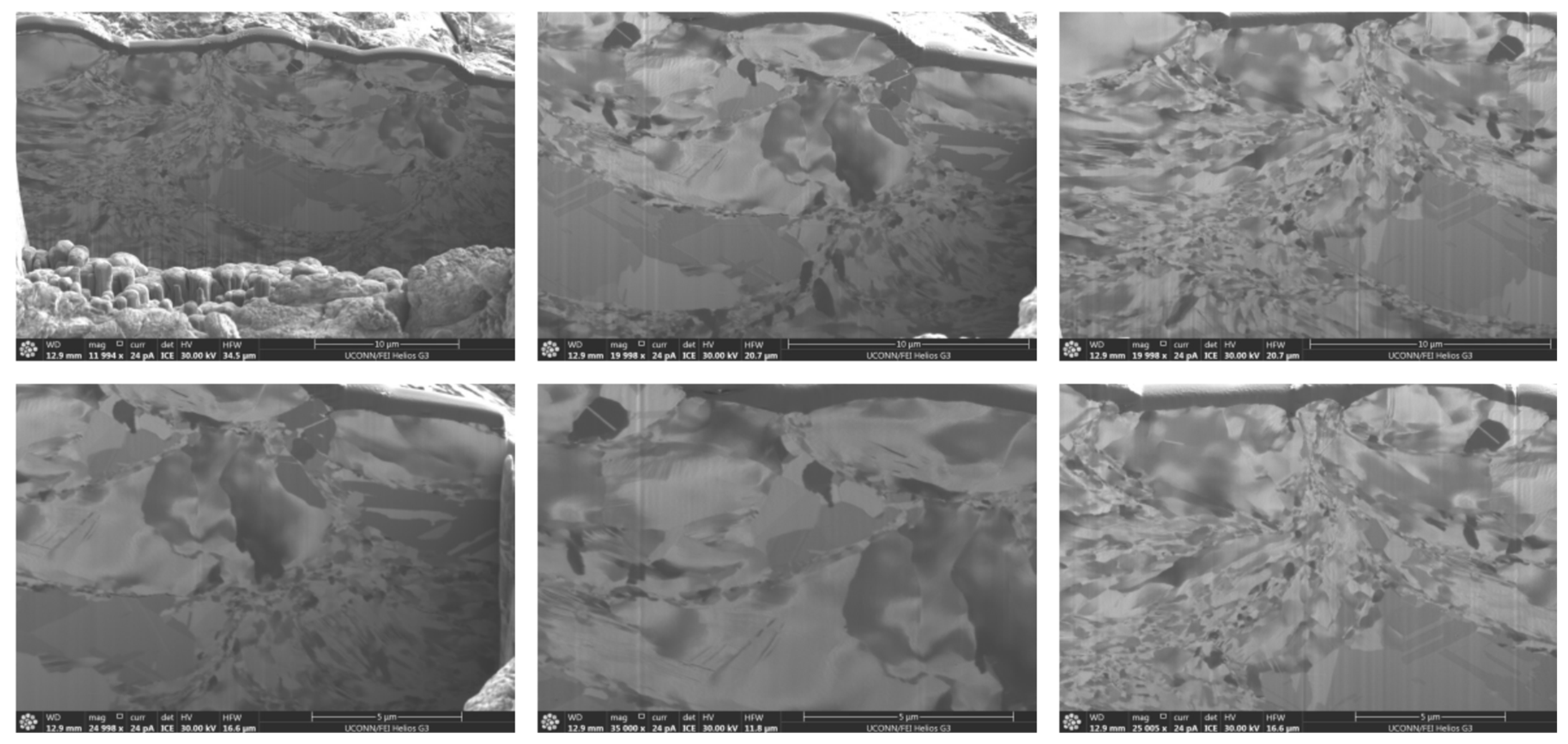
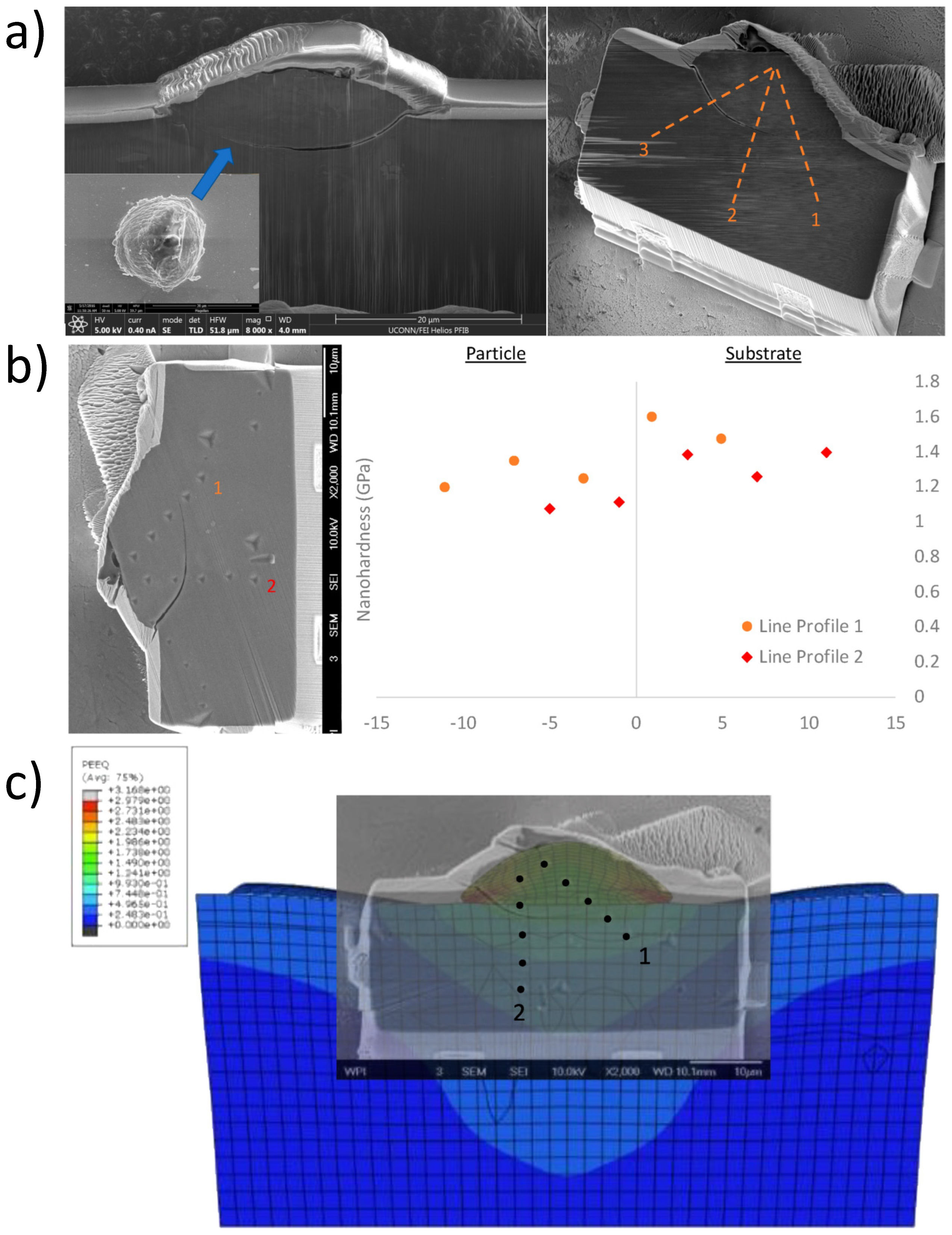
Single-particle impacts using an alternative sample procurement approach for gas-atomized Al 6061 are also shown in Figure 22a from orthogonal vantage points relative to the direction of the particulate approach [10]. From samples such as that shown in Figure 22a, nanoindentation grid arrays were conceptualized in Figure 22a,b, experimentally assessed as nanoindentation line profiles in Figure 22b, and related to the plastic equivalent strain state achieved for a similar system, as presented in Figure 22c [10].

7. Concluding Remarks

In the present work, we considered the microstructural and micromechanical property characterization for cold spray additive manufacturing in metallurgical and microparticulate feedstock. A careful microstructural and micromechanical evaluation of powder-based feedstock for cold spray processing follows that cold spray metal additive manufacturing (and deposition in general) is a fundamentally solid-state process. The mechanical and structural characteristics of a given feedstock for cold spray materials consolidation and processing are ultimately retained and refined via high strain rate impact phenomena and severe plastic deformation modalities. Due to the refining and retentive nature of cold spray additive manufacturing, proper property assessment of feedstock material systems enables tunable and optimized resultant component performance to be achieved through a structure–processing–properties–performance perspective. More to the point, a demonstration of advanced microscopy and nanoindentation-based analyses of particulate feedstock and their respective consolidated and cold-sprayed counterparts was provided in the present manuscript. Additional consideration of such microparticulate behaviors was also discussed considering through-process computational modeling of the cold spray process. The present work corroborates how controllable consolidated material performance and properties can be attained via appropriate microparticle feedstock pre-processing and characterization before use in cold spray metal additive manufacturing.

Author Contributions

Regarding the present review article—conceptualization, B.C.S., K.T. and D.L.C.; formal analysis, B.C.S., K.T. and D.L.C.; investigation, B.C.S., K.T. and D.L.C.; funding acquisition, D.L.C.; supervision, D.L.C.; visualization, B.C.S., K.T. and D.L.C.; writing—original draft, B.C.S., K.T. and D.L.C.; writing—review and editing, B.C.S. and K.T.; resources, D.L.C. All authors have read and agreed to the published version of the manuscript.

Funding

This work was funded by the United States Army Research Laboratory, grant #W911NF-19-20108.

Conflicts of Interest

The authors declare no conflict of interest. The funders had no role in the study’s design; in the collection, analyses, or interpretation of data; in the writing of the manuscript, or in the decision to publish the results.

References

  1. Wu, H.; Liu, S.; Zhang, Y.; Liao, H.; Raoelison, R.-N.; Deng, S. New Process Implementation to Enhance Cold Spray-Based Additive Manufacturing. J. Therm. Spray Technol. 2021, 30, 1284–1293. [Google Scholar] [CrossRef]
  2. Chavan, N.M.; Phani, P.S.; Ramakrishna, M.; Venkatesh, L.; Pant, P.; Sundararajan, G. Role of stacking fault energy (SFE) on the high strain rate deformation of cold sprayed Cu and Cu–Al alloy coatings. Mater. Sci. Eng. A 2021, 814, 141242. [Google Scholar] [CrossRef]
  3. Galvão, I.; Oliveira, J.C.; Loureiro, A.; Rodrigues, D. Formation and distribution of brittle structures in friction stir welding of aluminium and copper: Influence of process parameters. Sci. Technol. Weld. Join. 2011, 16, 681–689. [Google Scholar] [CrossRef]
  4. Hassani-Gangaraj, M.; Veysset, D.; Nelson, K.A.; Schuh, C.A. Melting Can Hinder Impact-Induced Adhesion. Phys. Rev. Lett. 2017, 119, 175701. [Google Scholar] [CrossRef] [PubMed] [Green Version]
  5. Walker, M. Microstructure and bonding mechanisms in cold spray coatings. Mater. Sci. Technol. 2018, 34, 2057–2077. [Google Scholar] [CrossRef]
  6. Massar, C.; Tsaknopoulos, K.; Sousa, B.C.; Grubbs, J.; Cote, D.L. Heat Treatment of Recycled Battlefield Stainless-Steel Scrap for Cold Spray Applications. JOM 2020, 72, 3080–3089. [Google Scholar] [CrossRef]
  7. Msolli, S.; Zhang, Z.-Q.; Seng, D.H.L.; Zhang, Z.; Guo, J.; Reddy, C.D.; Sridhar, N.; Pan, J.; Tan, B.H.; Loi, Q. An Experimentally Validated Dislocation Density Based Computational Framework for Predicting Micro-structural Evolution in Cold Spray Process. Int. J. Solids Struct. 2021, 225, 111065. [Google Scholar] [CrossRef]
  8. Sutton, A.T.; Kriewall, C.S.; Leu, M.C.; Newkirk, J.W.J.V.; Prototyping, P. Powder characterisation techniques and effects of powder characteristics on part properties in powder-bed fusion processes. Virtual Phys. Prototyp. 2017, 12, 3–29. [Google Scholar] [CrossRef]
  9. Munagala, V.N.V.; Akinyi, V.; Vo, P.; Chromik, R.R. Influence of Powder Morphology and Microstructure on the Cold Spray and Mechanical Properties of Ti6Al4V Coatings. J. Therm. Spray Technol. 2018, 27, 827–842. [Google Scholar] [CrossRef]
  10. Sousa, B.C.; Gleason, M.A.; Haddad, B.; Champagne, V.K., Jr.; Nardi, A.T.; Cote, D.L. Nanomechanical Characterization for Cold Spray: From Feedstock to Consolidated Material Properties. Metals 2020, 10, 1195. [Google Scholar] [CrossRef]
  11. Ning, X.-J.; Jang, J.-H.; Kim, H.-J. The effects of powder properties on in-flight particle velocity and deposition process during low pressure cold spray process. Appl. Surf. Sci. 2007, 253, 7449–7455. [Google Scholar] [CrossRef]
  12. Valente, R.; Ostapenko, A.; Sousa, B.C.; Grubbs, J.; Massar, C.J.; Cote, D.L.; Neamtu, R. Classifying Powder Flowability for Cold Spray Additive Manufacturing Using Machine Learning. In Proceedings of the 2020 IEEE International Conference on Big Data (Big Data), Atlanta, GA, USA, 10–13 December 2020; IEEE: New York, NY, USA, 2020; pp. 2919–2928. [Google Scholar]
  13. Sousa, B.; Walde, C.; Champagne, J.V.; Nardi, A.; Sisson, J.R.; Cote, D. Rapidly Solidified Gas-Atomized Aluminum Alloys Compared with Conventionally Cast Counterparts: Implications for Cold Spray Materials Consolidation. Coatings 2020, 10, 1035. [Google Scholar] [CrossRef]
  14. Heelan, J.; Langan, S.M.; Walde, C.; Nardi, A.; Siopis, M.; Barth, R.; Landry, T.; Birt, A. Effect of WC-Ni Powder Composition and Preparation on Cold Spray Performance. Coatings 2020, 10, 1196. [Google Scholar] [CrossRef]
  15. Moridi, A.; Hassani-Gangaraj, S.M.; Guagliano, M.; Dao, M. Cold spray coating: Review of material systems and future perspectives. Surf. Eng. 2013, 30, 369–395. [Google Scholar] [CrossRef]
  16. Te, A.; Sousa, B.; Mishra, B.; Cote, D. Subsurface Microstructural Evolution of High-Pressure Diecast A365: From Cast to Cold-Sprayed and Heat-Treated Conditions. Metals 2021, 11, 432. [Google Scholar] [CrossRef]
  17. Sousa, B.; Grubbs, J.; Cote, D. Cold Gas-Dynamic Spray as a Versatile Inorganic Material Deposition and Consolidation Technology. Mater. Matters 2021, 16, 37–43. [Google Scholar]
  18. Alkhimov, A.; Papyrin, A.; Kosarev, V. Gas-dynamic Spraying Method for Applying a Coating. U.S. Patent No. 5,302,414, 1994. [Google Scholar]
  19. Stoltenhoff, T.; Kreye, H.; Richter, H.J. An Analysis of the Cold Spray Process and Its Coatings. J. Therm. Spray Technol. 2002, 11, 542–550. [Google Scholar] [CrossRef]
  20. Petráčková, K.; Kondás, J.; Guagliano, M. Fixing a Hole (With Cold Spray). Int. J. Fatigue 2018, 110, 144–152. [Google Scholar] [CrossRef]
  21. Sova, A.; Grigoriev, S.; Okunkova, A.; Smurov, I. Potential of cold gas dynamic spray as additive manufacturing technology. Int. J. Adv. Manuf. Technol. 2013, 69, 2269–2278. [Google Scholar] [CrossRef]
  22. Wang, X.; Feng, F.; Klecka, M.A.; Mordasky, M.D.; Garofano, J.K.; El-Wardany, T.; Nardi, A.; Champagne, V.K. Characterization and modeling of the bonding process in cold spray additive manufacturing. Addit. Manuf. 2015, 8, 149–162. [Google Scholar] [CrossRef]
  23. Hussain, T.; McCartney, G.; Shipway, P.H.; Zhang, D. Bonding Mechanisms in Cold Spraying: The Contributions of Metallurgical and Mechanical Components. J. Therm. Spray Technol. 2009, 18, 364–379. [Google Scholar] [CrossRef]
  24. Wang, Q.; Birbilis, N.; Zhang, M.-X. Interfacial structure between particles in an aluminum deposit produced by cold spray. Mater. Lett. 2011, 65, 1576–1578. [Google Scholar] [CrossRef]
  25. Yin, S.; Suo, X.; Liao, H.; Guo, Z.; Wang, X. Significant influence of carrier gas temperature during the cold spray process. Surf. Eng. 2013, 30, 443–450. [Google Scholar] [CrossRef]
  26. Sousa, B.; Walde, C.; Champagne, V.; Cote, D. Initial Observation of Grain Orientation Dependent Nanoindentation Hardness of Al 6061 Gas-atomized Powder. Int. J. Metall. Met. Phys. 2020, 5, 1. [Google Scholar]
  27. Sousa, B.C.; Champagne, V.K.; Nardi, A.T.; Cote, D.L. Experimental Substantiation of Computational Thermodynamic, Kinetic, and Solidification Modeling for Cold Sprayable, Gas-atomized, Al 6061 Powder. Int J Met. Met Phys. 2020, 5, 061. [Google Scholar]
  28. Singh, H.; Sidhu, T.S.; Kalsi, S.B.S.; Karthikeyan, J. Development of cold spray from innovation to emerging future coating technology. J. Braz. Soc. Mech. Sci. Eng. 2013, 35, 231–245. [Google Scholar] [CrossRef]
  29. Irissou, E.; Legoux, J.-G.; Ryabinin, A.N.; Jodoin, B.; Moreau, C. Review on Cold Spray Process and Technology: Part I—Intellectual Property. J. Therm. Spray Technol. 2008, 17, 495–516. [Google Scholar] [CrossRef] [Green Version]
  30. Cavaliere, P.; Silvello, A. Processing Conditions Affecting Residual Stresses and Fatigue Properties of Cold Spray De-posits. Int. J. Adv. Manuf. Technol. 2015, 81, 1857–1862. [Google Scholar] [CrossRef]
  31. Belsito, D. Application of Computational Thermodynamic and Solidification Kinetics to Cold Sprayable Powder Alloy Design. Ph.D. Thesis, Worcester Polytechnic Institute, Worcester, MA, USA, 2014. [Google Scholar]
  32. Tsaknopoulos, K.; Sousa, B.; Massar, C.; Grubbs, J.; Siopis, M.; Cote, D. A Through-Process Experimental Approach to Enable Optimization of Cold Sprayed Al 7075 Consolidation Performance. JOM 2021, 74, 249–259. [Google Scholar] [CrossRef]
  33. Yeom, H.; Sridharan, K. Cold spray technology in nuclear energy applications: A review of recent advances. Ann. Nucl. Energy 2020, 150, 107835. [Google Scholar] [CrossRef]
  34. Schiel, J.F. The Cold Gas-dynamic Spray and Characterization of Microcrystalline Austenitic Stainless Steel. Master’s Thesis, Naval Postgraduate School, Monterey, CA, USA, 2014. [Google Scholar]
  35. Sundberg, K.; Sousa, B.C.; Schreiber, J.; Walde, C.E.; Eden, T.J.; Sisson, R.D.; Cote, D.L. Finite Element Modeling of Single-Particle Impacts for the Optimization of Antimicrobial Copper Cold Spray Coatings. J. Therm. Spray Technol. 2020, 29, 1847–1862. [Google Scholar] [CrossRef]
  36. Sousa, B.C.; Sundberg, K.L.; Gleason, M.A.; Cote, D.L. Understanding the Antipathogenic Performance of Nanostructured and Conventional Copper Cold Spray Material Consolidations and Coated Surfaces. Crystals 2020, 10, 504. [Google Scholar] [CrossRef]
  37. Handel, R. Cold Spray Aluminum Alloy Powder Characterization; Undergraduate Major Qualification Project Report; Worcester Polytechnic Institute: Worcester, MA, USA, 2015. [Google Scholar]
  38. Sundberg, K.; Gleason, M.; Haddad, B.; Champagne, V.K.; Brown, C.; Sisson, R.D.; Cote, D. The Effect of Nano-scale Surface Roughness on Copper Cold Spray Inactivation of Influenza A Virus. Int. J. Nanotechnol. Med. Eng. 2019, 4, 33–40. [Google Scholar]
  39. Sousa, B.; Cote, D.L. Supersonically Deposited Antiviral Copper Coatings. Adv. Mater. Process. 2021.
  40. McNally, B. Through-Process Modeling of Aluminum Alloys for Cold Spray: Experimental Characterization and Verification of Models. Ph.D. Thesis, Worcester Polytechnic Institute, Worcester, MA, USA, 2016. [Google Scholar]
  41. Tsaknopoulos, D. Optimization of Coupled Computational Modeling and Experimentation for Metallic Systems: Systematic Microstructural Feature—Mechanical Property Correlation for Cold-Sprayable Powders. Ph.D. Thesis, Worcester Polytechnic Institute, Worcester, MA, USA, 2019. [Google Scholar]
  42. Sousa, B. Multiscale Indentation Mechanics for Advanced and Heterogenous Metallurgical Materials Processing-Structure-Properties-Performance Relations. Ph.D. Thesis, Worcester Polytechnic Institute, Worcester, MA, USA, 2022. [Google Scholar]
Figure 1. Illustrative contextualization of the material, equipment, and process-level particularities associated with modern CSAM processing. (a) presents a schematic of the CS process as the powder exits the de Laval nozzle and forms a CS deposited material consolidation upon a target substrate. (b) presents an SEM micrograph of a suitable and gas-atomized powder feedstock for CS applications. (c) presents an SEM micrograph of a single microparticle from the powder shown in (b). (d) presents a cross-sectional SEM micrograph of a single powder particle from the feedstock shown in (b), which shows the microstructure of the particle. (e) presents an SEM micrograph from the CS deposit-substrate interfacial region, wherein a single particle is outlined in red. (f) presents a schematic of a high-pressure CS system’s configuration. (g) presents a graphical representation of the through-process model and approach to CS processing and CSAM consideration. (ae) were reproduced with permission from [26], Copyright Sousa et al., 2020. (f,g) were reproduced with permission from [27], Copyright Sousa et al., 2020.
Powders 01 00010 g001
Figure 2. (a) Nanoindentation-induced pile-up profiles associated with an array of Berkovich indents applied to a gas-atomized Al 6061 powder particle and captured via 3D confocal microscopy. (b) An additional example of 3D confocal microscopy for post-indentation characterization of Al 6061 CSAM feedstock. (c) A dynamic nanoindentation load–depth curve obtained for another Al 6061 CSAM feedstock microparticulate. (c,d) The dynamic stiffness squared per load versus dynamic nanoindentation depth curve for the same gas-atomized Al 6061 particle. (e) Another approach to analyzing and correcting nanoindentation data obtained when characterizing metallographically prepared powder for CS processing applications. (ad) were reproduced with permission from [10], Copyright Sousa et al., 2020. (e) was reproduced with permission from [34], Copyright Schiel, 2014.
Powders 01 00010 g002
Figure 3. Illustration of the consequences of relying on microindentation-based techniques to measure the hardness of powder particles. (a) the defocused nature of the micrograph shown post-microindentation, in addition to the asymmetry associated with the 4-sided pyramidal indent profile, demonstrates the occurrence of particle immersion during Vickers hardness testing of a metallic particle mounted in a compression mounting matrix and loaded to only 0.01 kgf. (b) also illustrates particle immersion into the mounting media, which occurred after particle decohesion from the matrix material was triggered. Note that the blue arrows in (a,b) identify the perimeter of the decohesion zone. Like (a,b), the powder shown in (c,d) was a gas-atomized Al alloy system; however, (c,d) identify clear examples where low-load microindentation of particulates result in plastic deformation zones that would encapsulate responses from both the mounting matrix and the hemispherical powder particle. (eg) present micrographs following Vickers indentation testing of a milled/crushed refractory metal feedstock, ultimately highlighting additional cases of immersion and inclination due to the compliance of the mounting matrix and the applied load of 0.01 kgf. (ag) were reproduced with permission from [10], Copyright Sousa et al., 2020.
Powders 01 00010 g003
Figure 4. Microstructure-based analysis for Al-based CSAM feedstock quantification for CSAM processing. (a) presents an SEM micrograph of an Al 6061 powder particle post-nanoindentation testing. (b) presents the EBSD image with an inverse pole figure (IPF) direction X orientation, for the same micrograph shown in (a). (c) presents a Miller indices color map coupled with grain-orientation dependent nanoindentation hardness responses for the same powder shown in (a,b). On the other hand, (d,e) present SEM micrographs of as-atomized and thermally treated gas-atomized Al 7075 feedstock powder particles. Finally, (f,g) present SEM and optical micrographs of chemically etched Al 7075 particulate cross-sections. (ac) were reproduced with permission from [10], Copyright Sousa et al., 2020. (dg) were reproduced with permission from [13], Copyright Sousa et al., 2020.
Powders 01 00010 g004
Figure 5. Illustration of various uses of microstructural analysis for Cu-based CSAM feedstock quantification for CSAM processing. (ac) presents EBSD analysis of gas-atomized and commercially pure Cu particulate feedstock after FIB milling. (dh) presents EDS analysis of GA Cu powder. Reproduced with permission from [36], Copyright Sousa et al., 2020.
Powders 01 00010 g005
Figure 6. Continued consideration of various uses of microstructural analysis for Al CSAM feedstock quantification for CSAM processing. (a) presents an SEM micrograph of as-atomized Al 6601 powder. (b) presents a laser scanning confocal micrograph of a rapidly solidified Al 5056 powder, which revealed a surface texture stemming from dendritic solidification mechanisms. (c,d) present secondary electron and backscatter electron SEM micrographs following cross-sectional Ar ion beam polishing. Note that the detection of Au within the EDS spectra shown in (f) was an artifact of Au-based sputter coating prior to SEM-EDS analysis. That said, (e,f) present chemically etched gas-atomized Al 2024 powder following 60 s of exposure to 0.5% aqueous hydrofluoric acid and EDS compositional results, respectively. Reproduced with permission from [10,37], Copyright Sousa et al., 2020, and Handel, 2015, respectively.
Powders 01 00010 g006
Figure 7. Illustration of various uses of micromechanical and indentation-based analysis for the quantification of various steel and Ti-based particulate CSAM feedstock materials’ properties. More specifically, the leftmost figure presents the modulus of elasticity versus hardness of the three categories of steel and Ti-based gas-atomized powders. On the other hand, the rightmost figure plots the resistance to elastic deformation and the ability to dissipate energy during plastic deformation alongside one another for the same three clusters of powder. Reproduced with permission from [10], Copyright Sousa et al., 2020.
Powders 01 00010 g007
Figure 8. Continued illustration of various micromechanical and indentation-based analysis uses for the quantification of four alloyed Al CSAM feedstock and CS consolidation properties. More specifically, the micrograph labeled “Powder” presents an SEM image of a grid of hardness indents on a single Al 6061 powder particle. The micrograph labeled “Consolidated” presents SEM image of a grid of hardness indents on the spray direction face of a consolidated Al 6061 coating. The coating was etched with 0.5% hydrofluoric acid solution for 5 s to reveal particle boundaries. A blue line highlights one particle boundary. Finally, the comparative bar plot depicts a graph of the average hardness for Al 6061, Al 2024, Al 7075, and Al 5056. The average hardness for all sizes of powder is shown by the solid bar, while the dashed bar represents the corresponding consolidated sample. Colors serve to differentiate between the alloys considered, which are labeled as such. Reproduced with permission from [10], Copyright Sousa et al., 2020.
Powders 01 00010 g008
Figure 9. Continued illustration of various micromechanical and indentation-based analysis uses for the quantification of CSAM material properties. Specifically, nanomechanical mapping methods were applied to a Cu-alloyed Al coating-substrate combination for hardness and modulus site-specific analysis. Reproduced with permission from [10], Copyright Sousa et al., 2020.
Powders 01 00010 g009
Figure 10. Illustration of microparticulate compression testing for mechanical characterization and analysis of CSAM feedstock. Reproduced with permission from [10], Copyright Sousa et al., 2020.
Powders 01 00010 g010
Figure 11. Continued illustration of a hybrid experimental–computational approach to assessing gas-atomized Cu CSAM feedstock powder-level properties. Reproduced with permission from [10], Copyright Sousa et al., 2020.
Powders 01 00010 g011
Figure 12. Continued illustration of a hybrid experimental–computational approach to relating Cu CSAM feedstock properties to particulate impact phenomena. Reproduced with permission from [35], Copyright Sundberg et al., 2020.
Powders 01 00010 g012
Figure 13. Continued illustration of a hybrid experimental–computational approach to assessing alloyed Al CSAM feedstock powder-level properties. That is, for gas-atomized Al 6061 powder, SEM micrographs of the as-atomized feedstock and an example of the measured secondary dendrite arm spacing used to substantiate the modeled grain size vs. particle size as a function of cooling rate and preprocessed condition are shown herein. Reproduced with permission from [10], Copyright Sousa et al., 2020.
Powders 01 00010 g013
Figure 14. Continued illustration of a hybrid experimental–computational approach to assessing gas-atomized Al-based CSAM feedstock powder-level properties. Reproduced with permission from [10,27], Copyright Sousa et al., 2020 and Sousa et al., 2020, respectively.
Powders 01 00010 g014
Figure 15. Continued illustration of a hybrid experimental–computational approach to assessing thermally pre-processed Al-based CSAM feedstock powder-level properties. Reproduced with permission from [10], Copyright Sousa et al., 2020.
Powders 01 00010 g015
Figure 16. Illustration of the utility of through-process modeling or characterization framework concerning microstructure–mechanical relations and considerations when applied to Al 6061 CS processing research and development. (a) presents etched particulate and consolidated material microstructures as a function of orientation relative to the direction of supersonic deposition during processing. In addition to the microstructural analysis shown in (a), (b) presents site-specific micromechanical properties of a gas-atomized Al 6061 particle and the corresponding consolidation procured. Reproduced with permission from [10], Copyright Sousa et al., 2020.
Powders 01 00010 g016
Figure 17. Continued illustration of the utility of through-process modeling or characterization framework concerning microstructure–mechanical relations and considerations applied to Al 6061 CS processing research and development. Reproduced with permission from [10], Copyright Sousa et al., 2020.
Powders 01 00010 g017
Figure 18. Illustration of the utility of through-process modeling or framework considerations when applied to gas-atomized Cu CS processing research and development. Finite element analysis of the impact-induced PEEQ profiles achieved following complete impact of a gas-atomized pure Cu powder particle onto an alloyed Al substrate via the (a) Johnson-Cook model and the (b) Preston-Tonks-Wallace for high strain-rate plastic deformation. (c) presents a corresponding Johnson-Cook model-based impact morphology of the deposit for the same microparticulate-substrate combination considered, as compared with (d) an optical micrograph of the deposit structure for the same system studied in-silico. Reproduced with permission from [35], Copyright Sundberg et al., 2020.
Powders 01 00010 g018
Figure 19. Continued illustration of the utility of through-process modeling or framework considerations applied to gas-atomized Cu CS processing research and development and their connection with resultant consolidation microstructural evolution. Each present cross-sectional high-resolution SEM micrographs of said CS processed material system following FIB milling. Note that the scale bars along the top row of micrographs were set to 10 μm, whereas the bottom row was set to 5 μm. Partly reproduced from the following sources [38,39] and so with permission, Copyright Sundberg et al., 2019.
Powders 01 00010 g019
Figure 20. Illustration of the utility of through-process modeling or framework considerations when applied to gas-atomized stainless steel CS processing research and development. Both powder size distribution, particulate morphologies, SEM micrographs–of the as-atomized stainless-steel feedstock–and hardness vs. thermal processing time of the powder are shown herein. Reproduced with permission from [6], Copyright Massar et al., 2020.
Powders 01 00010 g020
Figure 21. Illustration of an integrated experimental approach previously explored in conjunction with FEM formulation for single Al 6061 microparticle impact phenomena. (a) presents a single powder particle finite element analysis of the PEEQ achieved for the high-strain impact of a gas-atomized Al 6061 microparticle upon a target substrate. A microstructurally characterized cross-section of a comparable Al 6061 particle-substrate deposit was also presented to complement the computational analysis. (b) presents nanoindentation-based measurements of hardness and modulus of elasticity as a function of indent depth and location across the particle-substrate deposit system. Reproduced with permission from [10,42], Sousa et al., 2020, and Sousa, 2022.
Powders 01 00010 g021
Figure 22. Continued illustration of an integrated experimental approach previously explored in conjunction with FEM formulation for single Al 6061 microparticle impact phenomena. Single particle impacts for gas-atomized Al 6061 are shown in (a). Subsequent nanoindentation grid arrays are conceptualized and presented in (a,b); experimentally assessed as nanoindentation line profiles in (b); and related to the plastic equivalent strain achieved for a similar system as presented in (c) [10,42].
Powders 01 00010 g022
Publisher’s Note: MDPI stays neutral with regard to jurisdictional claims in published maps and institutional affiliations.

