1. Introduction
The European Spallation Source (ESS) [
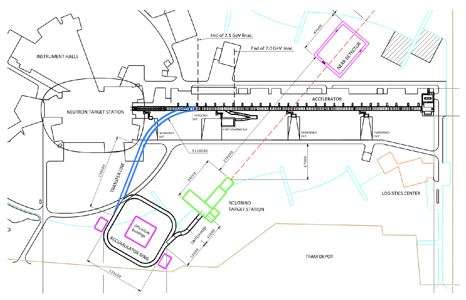
1], presently under construction in Lund, Sweden, will be the world’s highest brightness neutron source, powered by a 5 MW proton linac. The linac accelerates proton pulses to 2 GeV, at a repetition rate of 14 Hz and a duty cycle of 4%, and transports them to the target station. The RF cavities in the ESS linac can accept an up to 10% duty cycle, which means that it has the capability to provide an additional 5 MW of beam power. To this end, the ESS linac can, with moderate modifications (
Figure 1), be used for the production of a very intense neutrino beam.
The four year design study for the European Spallation Source Neutrino Super Beam [
2] (ESS
SB) was granted under the H2020 European framework and was conducted between 2018 and 2021. Its aim was to study the feasibility and design of a European Super Beam facility, based on the ESS proton linac, to measure, for the first time, the CP-violating phase in the leptonic sector. This study also preserved the possibility of adding new facilities to the proposed one, as potential next-generation upgrades can be guided by new physics results and scientific needs. These upgrades could be, for example, for projects on sterile neutrino searches, neutrino cross-section measurements, and muon cooling tests for a future muon collider. In addition, a Neutrino Factory could be envisaged using the large number of muons produced together with the muon neutrinos by the Super Beam facility. The main components of ESS
SB are: a proton driver, an accumulator ring, a target station, and the near and far detectors. In this paper, we summarize each of the components and also present the proposed continuation of this study, ESS
SB+, which will run between 2023 and 2027 with funding from Horizon Europe.
2. Proton Driver
The ESS LINAC, currently being constructed, will accelerate 14 proton pulses of 2.86 ms length per second. Each pulse contains about
protons, yielding a proton beam of 5 MW average power. The proposed power increase of the linac from 5 MW to 10 MW will be realized by increasing the pulse frequency from 14 Hz to 28 Hz, adding 14 more H
pulses of the same length and number of particles, interleaved with the proton pulses. The choice of a different species for the ESS
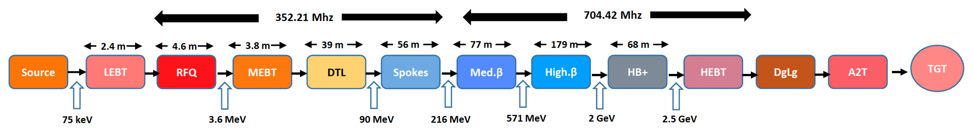
SB project comes from the fact that injection into the accumulator ring can be performed using charge exchange, while direct proton injection is a much more complex method. A layout of the proposed linac modification is shown in
Figure 2. The total number of particles delivered to the accumulator ring will be
per pulse cycle (macropulse), divided into four batches of
, each separated by gaps of 100 μ
length. Each batch will be stacked in the accumulator ring, compressing the 2.86 ms into four 1.2
pulses, which will be subsequently extracted to the target. The acceleration of H
ions requires the addition of a H
ion source to the side of the linac proton source and a doubling of the front-end accelerator elements up to the point where the proton and H
beam-lines are merged. For the H
production, the Penning source at ISIS-RAL and the RF source at SNS [
3,
4] were identified as the most promising ion sources to meet the ESS
SB requirements.
It is of primary interest that the beam exiting the linac is matched to the accumulator ring in order to have efficient injection and avoid losses. A linac-to-ring (L2R) transfer line has been designed to transport the 2.5 GeV H
beam output from the upgraded high-beta line (HB+) at the end of the linac to the Accumulator Ring (AR). At beam energies higher than about 100 MeV, activation of the machine components could become a concern, if the loss values exceed acceptable limits. The beam loss will be kept below 1 W/m, which ensures the maximum dose rate will be within acceptable values [
3]. Moreover, as mentioned before, several hardware modifications will need to be applied to the ESS LINAC in order to make it able to produce the intense neutrino beam. The modification program includes but is not limited to: the upgrade of the low-energy beam transport (LEBT), the medium-energy beam transport (MEBT), the radio-frequency quadrupole (RFQ), the drift-tube linac (DTL) tank, the modulator capacitor, and the cooling system.
3. Accumulator Ring
The underground accumulator ring, which has a circumference of about 380 m, will receive the four ca. 0.79 ms long subpulses separated by ca. 100 μs, which is the time needed to reconfigure the ring after the extraction of one subpulse before the next subpulse can be injected. Each subpulse will be injected during ca. 600 turns and then extracted in one turn, thus producing four ca. 1.2 μs long proton pulses separated by almost 0.9 μs that will each be sent to one of the four separate targets. The H pulse will be injected into the AR via a transfer line from the linac, through charge-exchange injection with phase-space painting, where the closed orbit of the circulating proton beam is gradually moved with respect to the fixed position of the injected beam. In this way, the beam will be shaped so as to limit the detrimental effects of the space charge. As a round-beam cross section is desirable when the beam hits the target, anti-correlated painting of the beam has been opted for. The injected H ions will be stripped at the entrance to the AR using thin carbon foils. The temperature to which these foils are heated must be kept below 2000 K, above which the foil sublimation rate will be too high. To achieve this, the injected beam will be mismatched to the circulating beam so that the energy deposition will be spread over a larger foil area. Four thinner foils, stacked one behind the other, will be used rather than a single thicker foil, in order to increase the effective radiating surface and, through this, help the cooldown. It is planned to investigate, as an alternative to foil stripping, the use of a laser beam to strip the incoming H ions. This method is currently being developed at the SNS in the USA.
The design of the accumulator beam lattice has been carried out using both beam optics and multiparticle simulations. The simulations show that a geometric 100% emittance as low as 60
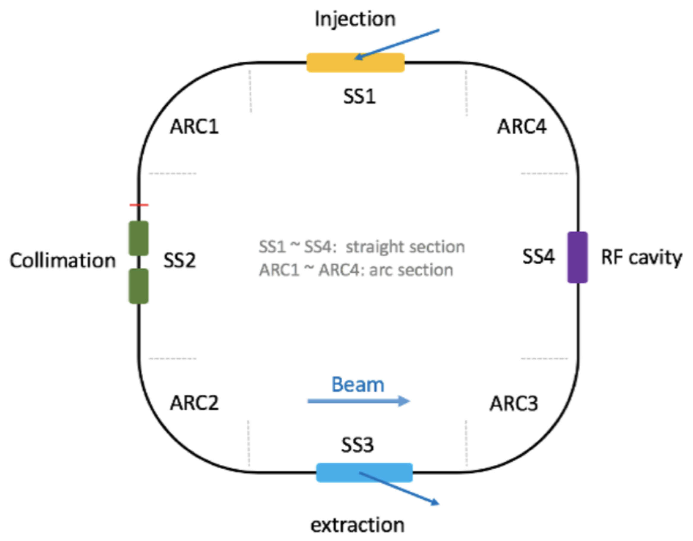
mm mrad is achievable. The total tune spread expected is around 0.05, which means that the space charge is not a problem for the AR design. We chose an accumulator layout that has four rather short arcs connected by relatively long straight sections, see
Figure 3. The main challenges of the design at present are to control the beam loss and to find a H
stripping scheme that is reliable over time. The design of a two-stage collimation system has been made to meet these challenges. A barrier RF cavity will be used to contain the beam pulses longitudinally and preserve the 100 ns particle-free gap required for extraction. The beam will be extracted from the ring using a set of vertical kicker magnets and a horizontal septum, and the four subpulses will be guided by a 72 m transfer line and a switch yard to the four separate targets.
After their extraction from the accumulator, the protons will propagate through a beam line up to a beam switchyard (BSY), in order to be distributed onto the four targets.
4. Target Station
Four identical separate targets will be operated in parallel in order to reduce the beam power that a single target will have to sustain, i.e., from 5 MW/target to 1.25 MW/target. The target design is based on a tube-shaped canister, of ca. 3 cm diameter and ca. 70 cm length, filled with 3 mm diameter titanium beads and cooled using a forced transverse flow of helium gas, pressurized at 10 bar. The primary advantage of such design, in comparison to the monolithic targets, lies in the possibility of making the cooling medium flow directly through the target and, by doing so, allowing a better heat removal from the target areas of highest power deposition. Each target is surrounded by a pulsed magnetic horn providing a strong toroidal field, with a value of the magnetic field strength of
T at peak current. This is required for the focusing of the charged pion beam, which is produced from the interaction between the impinging protons and the titanium target. Pions produced in the forward direction are sent into a 50 m long decay tunnel filled with helium gas to reduce secondary interactions. The charge sign of the pions being focused will be changed by inverting the direction of the current in the horn. Each horn will have a separate power supply unit capable of providing a 350 kA current pulse with a flat top of 1.3 μs that will be sent to the horn through strip lines. Several horn designs were investigated in this study, of which the Van der Meer horn structure [
2] showed the best performance. The geometry of the horn has been designed and optimized using a so-called genetic algorithm to provide optimal signal efficiency in the Far Detector.
5. Near and Far Detectors
The purpose of the Near Detector (ND) is to monitor the neutrino beam intensity and to measure the muon- and electron-neutrino cross sections, in particular their ratio, which is important for minimizing the systematic uncertainties in the experiment. The ND will be located underground within the ESS site ca. 250 m from the target station (see
Figure 1). It will be composed of three coupled detectors: a kiloton mass Water Cherenkov detector (WatCh), which will be used for event rate measurement, flux normalization, and event reconstruction comparison with the Far Detector, a magnetized super Fine-Grained Detector [
2], located inside a 1 T dipole for measurements of the poorly known neutrino cross sections in the energy region below 600 MeV and placed upstream of and adjacent to the water volume, and an emulsion detector of similar type as in the NINJA experiment [
5].
The Far Detector (FD), which will detect the rate and energy distributions of the muon and electron neutrinos, respectively, will be composed of two vertical cylinders of ca. 74 m in height and ca. 74 m in diameter, installed in caverns ca. 1000 m below ground level to protect it from the cosmic radiation background. Two locations for the FD are under consideration, both near the position of the second oscillation maximum, thereby resulting in a majority of the events being collected at the second oscillation maximum. One location is in the Zinkgruvan mine, 360 km from the ESS, and the other is in the Garpenberg mine, 540 km from the ESS. The photo multiplier tubes coverage of the ca. 25,000 m inner detector walls will be 40% (requiring, e.g., ca. 50,000 PMTs of 20 inch diameter). The water in the detector tanks will be purified using an industrial-sized water-cleaning plant in order to achieve about 100 m absorption length for the light wavelength that the PMTs are sensitive to. The ability to dissolve gadolinium salt for increased neutron detection efficiency, and thereby of electron antineutrinos, will be included.
6. Next Steps: ESSSB+
The key objective of the H2020 ESSSB Design Study was to demonstrate the feasibility of using the European Spallation Source proton linac to produce the world’s most intense neutrino beam concurrently with the 5 MW proton beam that will be used for the production of spallation neutrons. After the production of all deliverables and the publication of the ESSSB CDR, this has now been accomplished. The present Design Study is proposed to pave the way for the ESSSB by introducing complementary studies and enlarging its scope by introducing investigations of synergetic projects. The ESSSB+ strategic objectives are: to conduct all the civil engineering and geotechnical studies for the ESS site and far detector, to study a secondary target for a Low-Energy STORM decay ring facility for cross-section measurements and for sterile neutrino searches, and to carry out studies of the geotechnical characteristics of the currently preferred site at Zinkgruvan.


