1. Introduction
The main ring synchrotron (MR) [
1] of Japan Proton Accelerator Research Complex (J-PARC) [
2] provides high power proton beams with a kinetic energy of 30 GeV for the T2K experiment [
3,
4,
5] by fast extraction (FX). The MR set a world record for the beam intensity of
protons per pulse (ppp), corresponding to the beam power of 515 kW [
6]. To realize higher statistic physical experiments, we launched an upgrade plan aiming at 1.3 MW FX operation [
7]. This upgrade plan consists of higher repetition, reinforcement of the RF system, and beam loss reduction/localization. As the first step, we upgraded all the machines for high repetition and shortened the cycling period from 2.48 s to 1.36 s. All the power supplies of the main magnets were replaced during the long shutdown in JFY2021. This paper reports the first results of the beam commissioning with a cycling period of 1.36 s.
2. Hardware Upgrade
The combination of the magnets which is ramped by the same power supply is called “family” in the MR. The bending magnets were ramped by 6 power supplies, that is, there are 6 families for the bending magnets. All the power supplies of the bending magnets were newly constructed with capacitor banks.
The quadrupole magnets were ramped by 11 power supplies in total until 2021: 7 families for the straight sections and 4 families for the arc sections. The combinations of the quadrupole magnets were chosen so that the MR could secure three-fold symmetry. In 2021, two power supplies for the arc sections were newly constructed with capacitor banks. On the other hand, the remaining two families for the arc sections were split. We realized significant cost reduction by reusing the previous power supplies. As a result, the number of families for the arc section increased from 4 to 6. Since these families were split without satisfying the three-fold symmetry due to the cabling problem, the magnetic fields of the split families should be the same values. In the straight sections, 3 families were split and the total number of families became 10.
In contrast to the quadrupole magnets, the families for the sextupole magnets were combined. The power supplies were newly constructed without capacitor banks. The number of families becomes from 3 to 2.
Many other hardware were also upgraded during the long shutdown. The low-level RF control system [
8] was replaced with the new-generation system implementing multi-harmonic vector voltage feedback control and longitudinal mode-by-mode feedback control, enabling suppression of longitudinal dipole oscillations induced by the coupled bunch instability.
The FX septum magnets were also newly constructed. The low-field septum magnets employ eddy-current type [
9]. Inner pure iron shields were installed in all the septum magnets to reduce the leakage fields which had caused beta modulations.
The upgrade of the collimator system is also ongoing. We are increasing the collimators in order to improve the localization efficiency of beam losses by covering wider phase space regions. The number of the collimators became from 4 to 6 in Summer 2022, and it will be 7 in Summer 2023, corresponding to the capacity of 3.5 kW.
3. Results of Beam Commissioning
The beam study was performed using beams with a kinetic energy of 3 GeV which is the injection energy. In the user operation, two-bunch beams are injected four times at intervals of 40 ms during the injection period (130 ms). In this beam study, we used a single two-bunch beam and circulated it 220 ms to minimize current-dependent effects such as bunch train tune shift.
3.1. Optics Adjustment
In the beginning, we adjusted the beam optics using weak intensity beams with an intensity of
protons per bunch (ppb). After adjustment, the tune was
where
and
are the model and measured tunes, respectively. The measured tunes matched the models within the margins of errors. The tune errors originated from the current ripple of power supplies of main magnets.
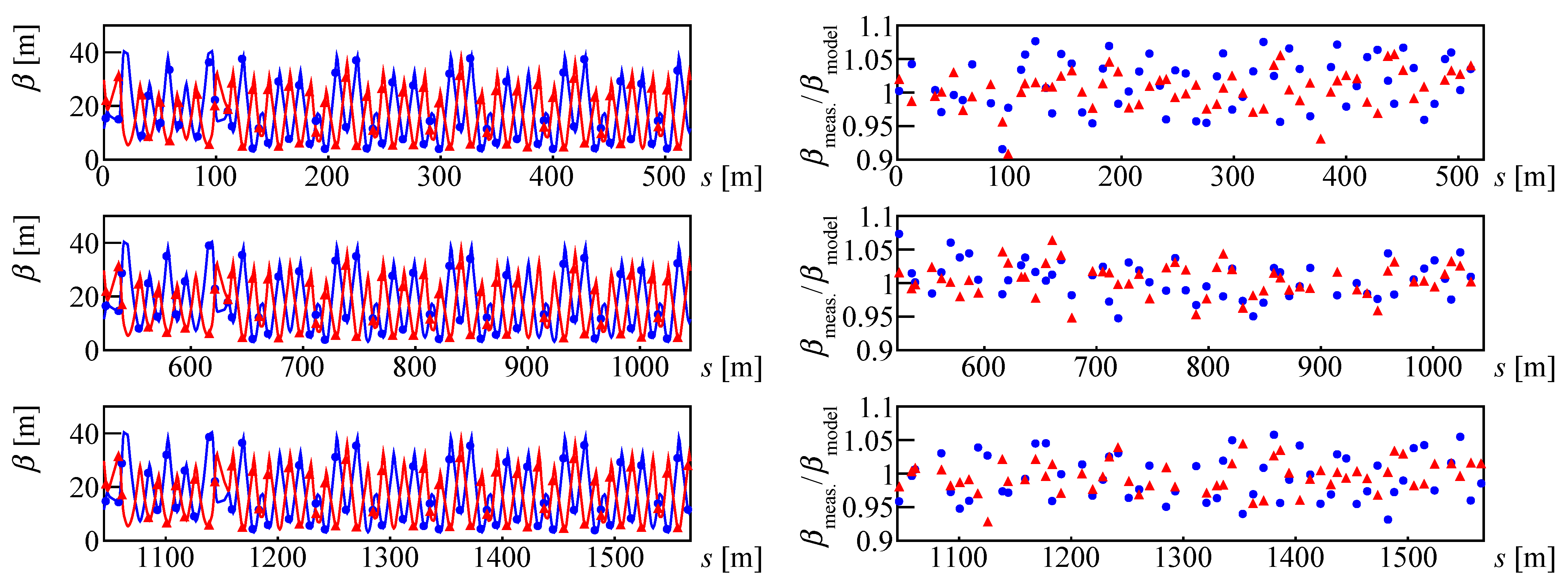
The beta functions were also measured via the Fourier analysis of turn-by-turn transverse dipole oscillation using 512 turns. The results are shown in
Figure 1. The RMSs of the ratios of measured betas
to model betas
were
These 3% errors are consistent with previous measurements before hardware upgrade. The precision of the beam position monitors (BPMs) in turn-by-turn measurements is approximately . The 3% beta modulation can be explained by this BPM precision.
The dispersion function was also measured; the measured and model dispersions were in good agreement. The MR employs an achromat lattice in its arc sections. The leakage of the dispersion in the straight sections
was evaluated as
which was small enough.
3.2. Ripple Measurement
The fractional current deviation below 200 Hz of the new power supplies of the bending magnets is 10 times smaller than that of the old power supplies [
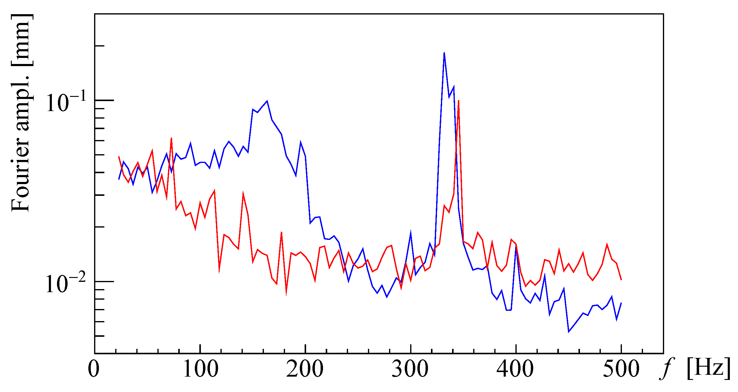
10]. To verify this improvement, we measured horizontal beam positions for 220 ms at intervals of 1 ms. The beam positions at the high-dispersion position, where the model dispersion is
, was analyzed via Fourier transformation. The same measurements were also performed before the upgrade of the power supplies of the bending magnets. The results are shown in
Figure 2. The beam ripple in the range of 80–220 Hz using the new power supplies (red line) was successfully suppressed compared to the ripple using the old power supplies (blue line). By further optimization of the power supplies, the ripple below 80 Hz will also be lowered. The spectra appearing around at 340 Hz correspond to the synchrotron frequency; their differences do not necessarily show the difference of old and new power supplies because they depend on longitudinal dipole oscillations.
3.3. Beam Loss Measurement
Currently, the anode power supplies of the RF cavities limit the beam intensity of the MR. As the cycling period becomes short, the synchronous phase during the acceleration period should be larger. The maximum beam intensity is estimated as 1.8– ppp at present. The RF system will be upgraded step-by-step and it will eventually be able to accelerate high intensity beams with an intensity of ppp. The beam loss study was performed using two-bunch beams with an intensity of ppb, corresponding to ppp for 8 bunches, taking into consideration the upcoming FX user operation.
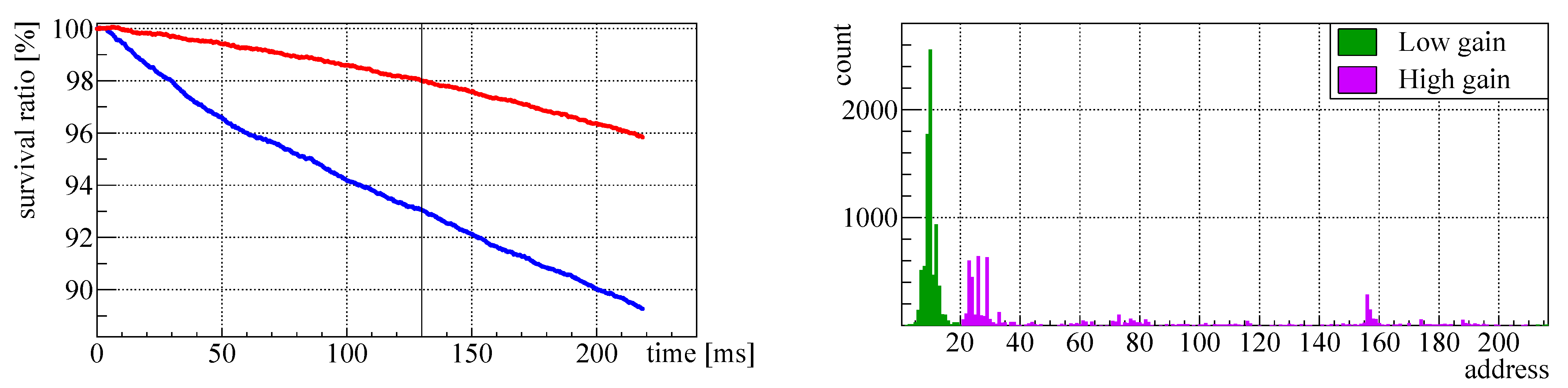
Figure 3 shows the beam survival ratios measured by the direct-current current transformer (DCCT) after adjustments (red line in the left panel) and beam loss counts measured by the proportional beam loss monitors (right panel). The beam loss during the beam injection period (130 ms) was 2%. It is slightly worse than the beam loss in the previous user operation (1%). On the other hand, the beam loss localization quality was very high. Since the limitation for the user operation is the beam loss at the non-collimator area, and besides the collimator system was upgraded after this beam study, this beam condition is acceptable for the user operation. Considering the beam loss of 2%, the intensity of
ppb corresponds to the beam power of 740 kW, which is almost the same as the original design parameter of 750 kW.
4. Discussion for the Beam Survival
Effects of Family Splitting
The main cause for the deterioration of the beam survival was three-fold symmetry breaking of the beam optics due to splitting several quadrupole families. In fact, we verified its effect by comparing the two beam optics before and after adjusting the quadrupole families in the arc sections.
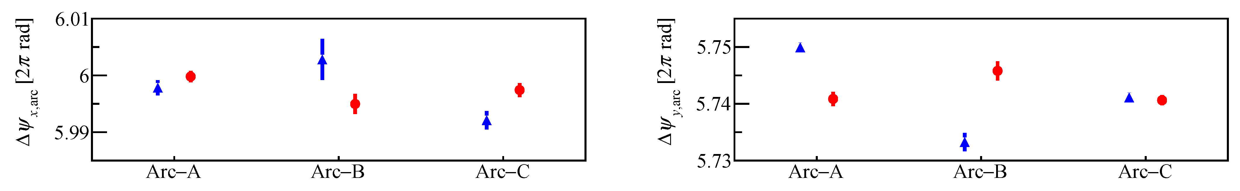
Figure 4 shows the measured phase advances of the three arc sections in the MR. The phase advances were measured using the BPMs at the boundaries of the straight sections and the arc sections by the Fourier analysis of turn-by-turn transverse dipole oscillations. Both the horizontal and vertical phase advances of the three arc sections differed from each other before adjusting the families. The differences of the magnetic fields between the split families were estimated to be 0.5%. After the adjustment, the phase variations became small and the magnetic field differences between the split families were estimated to be 0.1%.
The beam survival ratios were measured with both optics, shown in the left panel of
Figure 3. With the optics before adjustment (blue), the beam loss during the beam injection period (130 ms) was 7%. It was much worse than the beam loss after adjustment of the split families. It proves that the three-fold symmetry breaking provokes severe beam losses.
In
Figure 4, even with the beam optics after adjustment, there were statistically significant differences among the three phase advances. It indicates that the beam loss can be minimized by better phase balancing. In the MR, correction quadrupole magnetic fields were added by energizing the coils at three quadrupole magnets using independent power supplies. Originally, these hardware for correction fields were installed to cancel the leakage fields at the FX septum magnets, but now the leakage fields are small enough [
9]. We are planning to reuse and increase them for phase balancing and tune operation against bunch train tune shifts. By recovering three-fold symmetry using correction quadrupole fields, nonstructure resonances can be suppressed, resulting in beam loss reduction.
5. Conclusions
In the J-PARC MR, we upgraded hardware to enable FX operations with a cycling period of 1.36 s and to realize FX operation with a beam power of 1.3 MW in the future. We performed beam studies with a high repetition period in June 2022. The beam optics was carefully adjusted and the tunes, beta functions, and dispersion functions were reproduced with almost the same precisions of the previous measurements before upgrade. We also verified that ripples of the power supplies of the bending magnets were lowered in the range of 80–220 Hz. In this upgrade, several power supplies of quadrupole magnets were split. It caused three-fold symmetry breaking of the beam optics, resulting in deterioration of the beam survival. We performed beam loss studies using beams with an intensity of ppb. Before adjusting the split quadrupole families in the arc sections, the beam loss during the beam injection period was 7%. After adjustment, it recovered to 2%. Although 2% loss is still worse than the beam loss before upgrade, it is acceptable for the user operation because the beam loss localization quality was very high and the collimator system was upgraded. This beam intensity corresponds to 740 kW operation, considering 2% loss. We have successfully verified the beam optics for the 740 kW FX operation. We also measured the phase advances in the arc sections. Even after the adjustment, variations of three phase advance were measured, indicating necessity of further phase balancing. We are planning to add correction quadrupole magnetic fields at multiple places to recover the three-fold symmetry. It will suppress nonstructure resonances and reduce beam losses.
After JFY2022, the RF system is going to be upgraded step-by-step. By reinforcing the anode power supplies and increasing the number of RF cavities, we will be able to accelerate beams with an intensity of
ppp. The study for beam optics is also ongoing. We are planning to apply the new beam optics which can compensate or suppress several strong structure resonances [
11].
Author Contributions
Conceptualization, T.Y. and Y.S.; methodology, T.Y. and Y.S.; software, T.Y.; validation, T.Y. and Y.S.; formal analysis, T.Y.; investigation, T.Y. and Y.S.; resources, T.Y.; data curation, T.Y.; writing—original draft preparation, T.Y.; writing—review and editing, T.Y.; visualization, T.Y.; supervision, Y.S., H.H. and S.I.; project administration, H.H. and S.I.; funding acquisition, H.H. and S.I. All authors have read and agreed to the published version of the manuscript.
Funding
This research received no external funding.
Institutional Review Board Statement
Not applicable.
Informed Consent Statement
Not applicable.
Data Availability Statement
Not applicable.
Acknowledgments
We would like to thank all members of the J-PARC MR for their support.
Conflicts of Interest
The authors declare no conflict of interest.
References
- Koseki, T.; Arakaki, Y.; Chin, Y.H.; Hara, K.; Hasegawa, K.; Hashimoto, Y.; Hori, Y.; Igarashi, S.; Ishii, K.; Kamikubota, N.; et al. Beam commissioning and operation of the J-PARC main ring synchrotron. Prog. Theor. Exp. Phys. 2012, 2012, 02B004. [Google Scholar] [CrossRef]
- High-Intensity Proton Accelerator Project Team. Accelerator Technical Design report for High-Intensity Proton Accelerator Facility Project, J-PARC, KEK-Report 2002-13 and JAERI-TECH 2003-044, Japan Atomic Energy Research Institute, Tokai-mura, Naka-gun, Ibaraki-ken, Japan (2003). Available online: https://jopss.jaea.go.jp/pdfdata/JAERI-Tech-2003-044.pdf (accessed on 26 July 2023).
- Abe, K.; Abgrall, N.; Ajima, Y.; Aihara, H.; Albert, J.B.; Andreopoulos, C.; Andrieu, B.; Aoki, S.; Araoka, O.; Argyriades, J.; et al. Indication of electron neutrino appearance from an accelerator-produced off-axis muon neutrino beam. Phys. Rev. Lett. 2011, 107, 041801. [Google Scholar] [CrossRef] [PubMed] [Green Version]
- Abe, K.; Adam, J.; Aihara, H.; Akiri, T.; Andreopoulos, C.; Aoki, S.; Ariga, A.; Ariga, T.; Assylbekov, S.; Autiero, D.; et al. Observation of electron neutrino appearance in a muon neutrino beam. Phys. Rev. Lett. 2014, 112, 061802. [Google Scholar] [CrossRef] [PubMed] [Green Version]
- The T2K Collaboration. Constraint on the matter-antimatter symmetry-violating phase in neutrino oscillations. Nature 2020, 580, 339–344. [Google Scholar] [CrossRef] [PubMed] [Green Version]
- Kurimoto, Y.; Sato, Y. Upgrade plan of J-PARC main ring. J. Part. Accel. Soc. Jpn. 2021, 18, 10–20. (In Japanese) [Google Scholar]
- Igarashi, S.; Satou, K.; Ohmori, C.; Arakaki, Y.; Furusawa, M.; Hara, K.; Hasegawa, K.; Hashimoto, Y.; Hori, Y.; Hotchi, H.; et al. Accelerator design for 1.3-MW beam power operation of the J-PARC main ring. Prog. Theor. Exp. Phys. 2021, 2021, 033G01. [Google Scholar] [CrossRef]
- Yoshii, M.; Ohmori, C.; Hara, K.; Hasegawa, K.; Sugiyama, Y.; Furusawa, M.; Yamamoto, M.; Tamura, F.; Shimada, T.; Nomura, M. Present status and future upgrades of the J-PARC ring RF systems. In Proceedings of the IPAC’18, Vancouver, BC, Canada, 29 April–4 May 2018; pp. 984–986. [Google Scholar]
- Shibata, T.; Ishii, K.; Iwata, S.; Sugimoto, T.; Matsumoto, H.; Fan, K. The new eddy current type septum magnet for upgrading of fast extraction in main ring of J-PARC. In Proceedings of the IPAC’22, Bangkok, Thailand, 12–17 June 2022; JACoW Publishing: Geneva, Switzerland, 2022. [Google Scholar]
- Shimogawa, T.; Kurimoto, Y.; Morita, Y.; Miura, K.; Naito, D. New power supply of main magnets for J-PARC main ring upgrade. In Proceedings of the IPAC’19, Melbourne, Australia, 19–24 May 2019; JACoW Publishing: Geneva, Switzerland, 2019. [Google Scholar]
- Yasui, T.; Igarashi, S.; Sato, Y.; Koseki, T. Beam optics for the compensation of third-order structure resonances. Prog. Theor. Exp. Phys. 2022, 2022, 013G01. [Google Scholar] [CrossRef]
| Disclaimer/Publisher’s Note: The statements, opinions and data contained in all publications are solely those of the individual author(s) and contributor(s) and not of MDPI and/or the editor(s). MDPI and/or the editor(s) disclaim responsibility for any injury to people or property resulting from any ideas, methods, instructions or products referred to in the content. |
© 2023 by the authors. Licensee MDPI, Basel, Switzerland. This article is an open access article distributed under the terms and conditions of the Creative Commons Attribution (CC BY) license (https://creativecommons.org/licenses/by/4.0/).


