
Interdigital H-Mode Drift Tube Linear Accelerator for a Muon Linear Accelerator †

 , , ,
, , ,  ,
,
Abstract
:1. Introduction
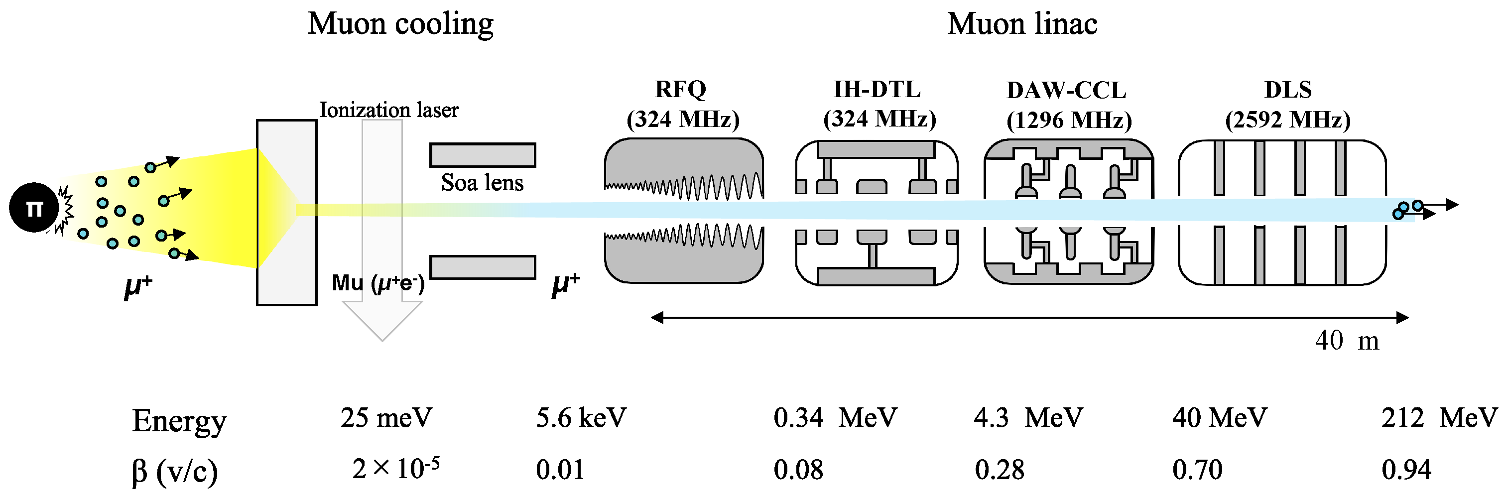
2. Muon Linear Accelerator
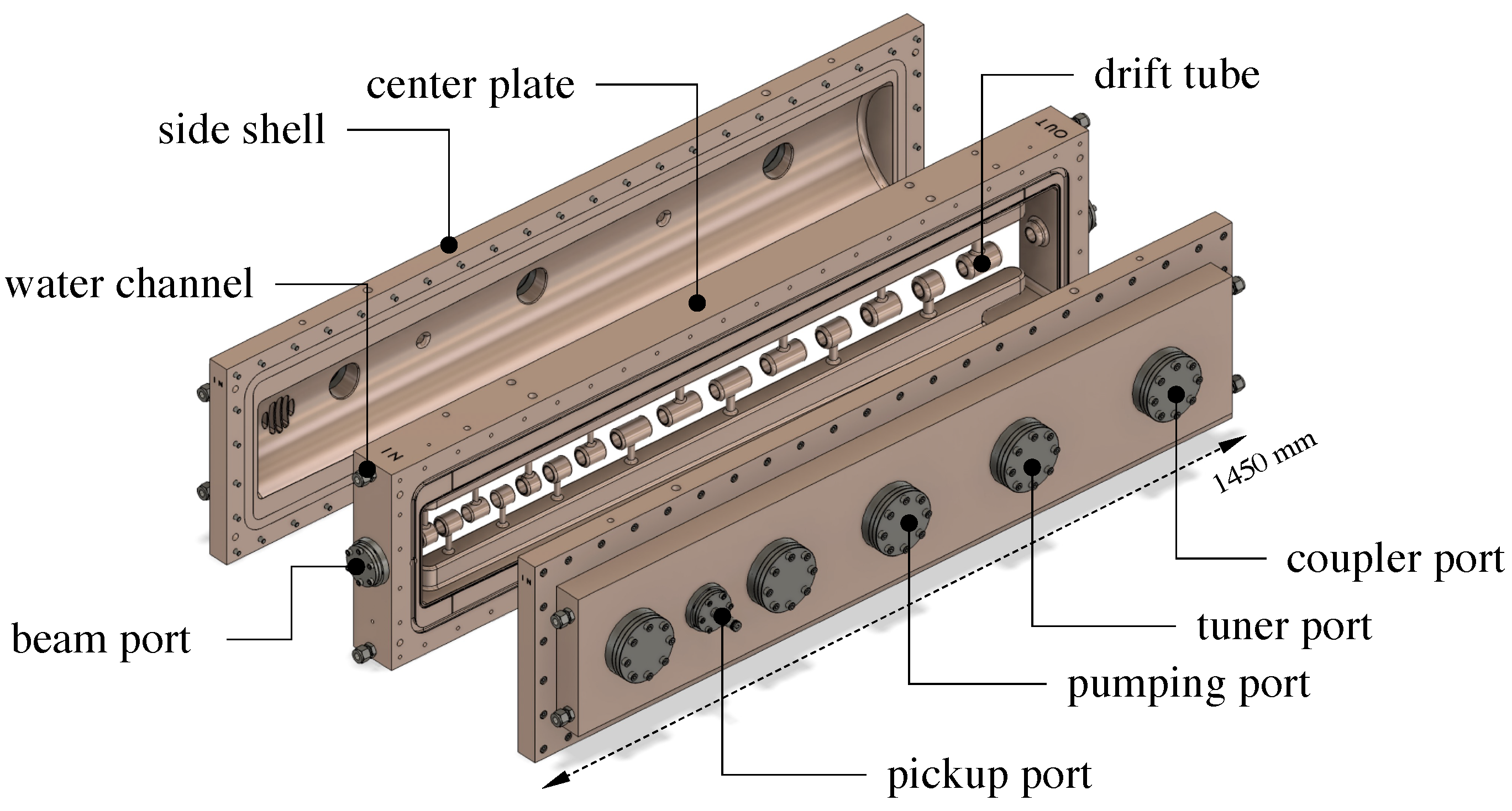
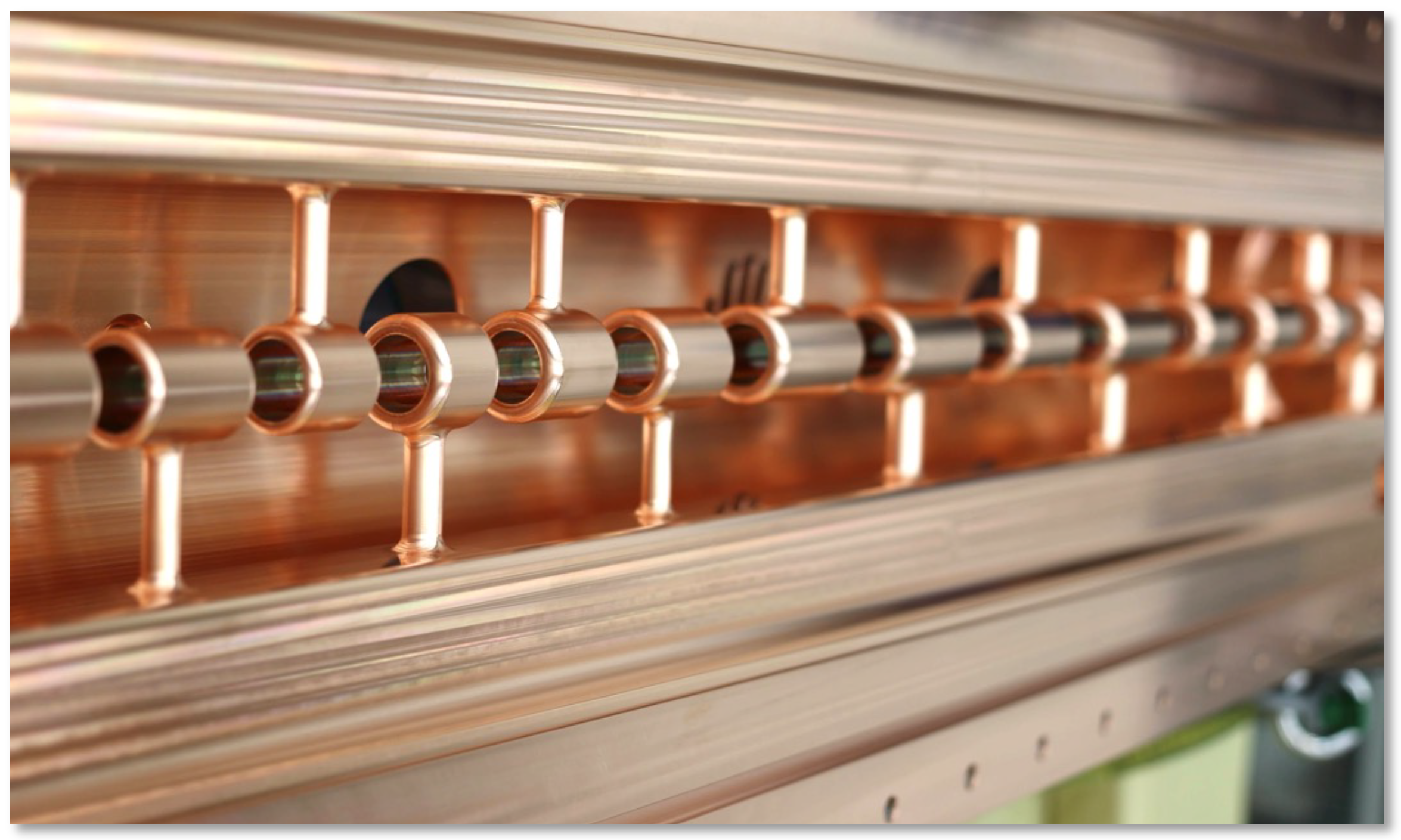
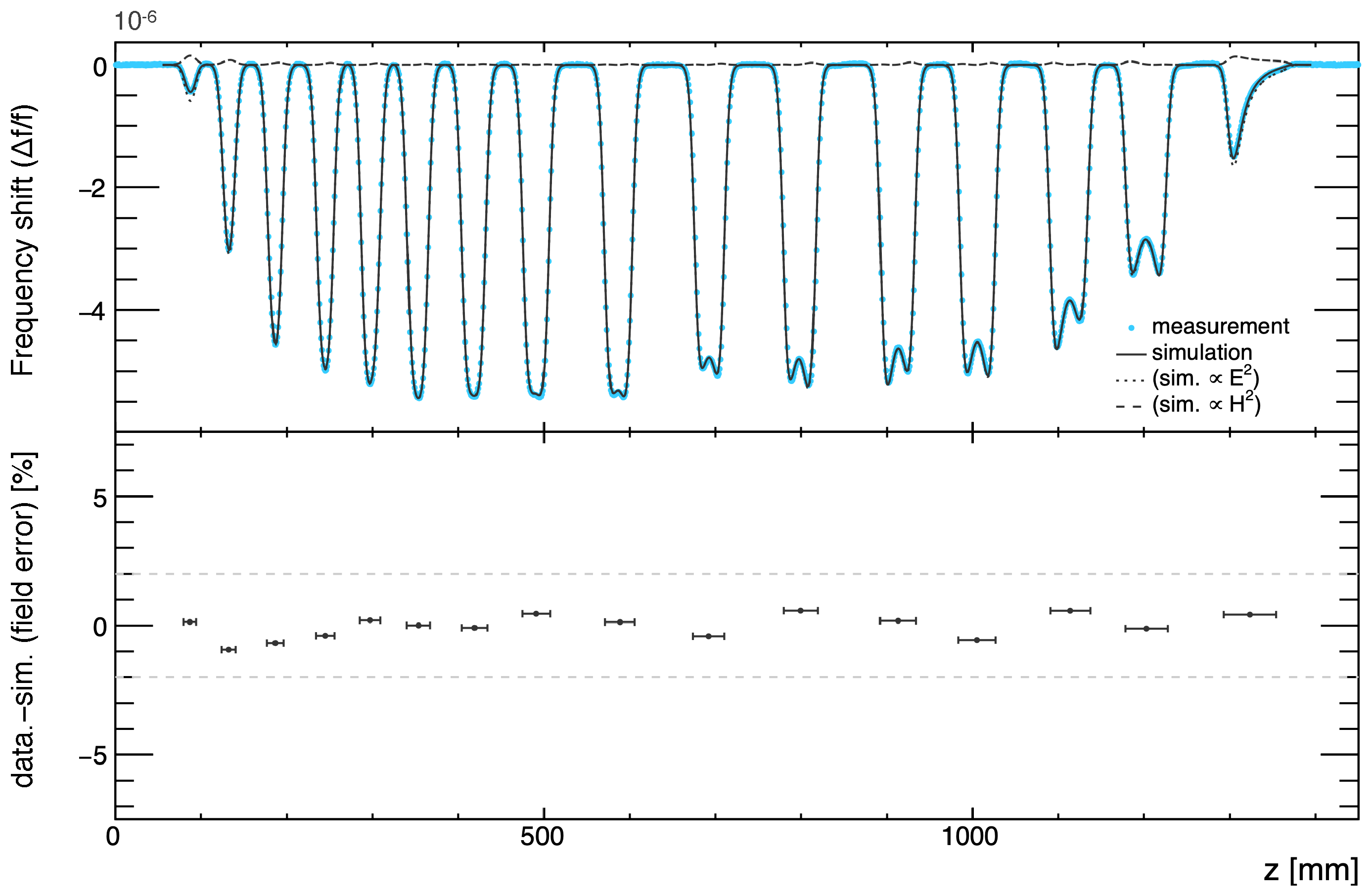
3. Development of the IH-DTL
4. Summary and Prospects
Author Contributions
Funding
Institutional Review Board Statement
Informed Consent Statement
Data Availability Statement
Acknowledgments
Conflicts of Interest
References
- Bennett, G.W.; Bousquet, B.; Brown, H.N.; Bunce, G.; Carey, R.M.; Cushman, P.; Danby, G.T.; Debevec, P.T.; Deile, M.; Deng, H.; et al. Final report of the E821 muon anomalous magnetic moment measurement at BNL. Phys. Rev. D 2006, 73, 072003. [Google Scholar] [CrossRef] [Green Version]
- Abi, B.; Albahri, T.; Al-Kilani, S.; Allspach, D.; Alonzi, L.P.; Anastasi, A.; Anisenkov, A.; Azfar, F.; Badgley, K.; Baeßler, S.; et al. Measurement of the positive muon anomalous magnetic moment to 0.46 ppm. Phys. Rev. Lett. 2021, 126, 141801. [Google Scholar] [CrossRef] [PubMed]
- Aoyama, T.; Asmussen, N.; Benayoun, M.; Bijnens, J.; Blum, T.; Bruno, M.; Caprini, I.; Calame, C.C.; Cè, M.; Colangelo, G.; et al. The anomalous magnetic moment of the muon in the Standard Model. Phys. Rep. 2020, 887, 1–166. [Google Scholar] [CrossRef]
- Abe, M.; Bae, S.; Beer, G.; Bunce, G.; Choi, H.; Choi, S.; Chung, M.; Da Silva, W.; Eidelman, S.; Finger, M.; et al. A new approach for measuring the muon anomalous magnetic moment and electric dipole moment. Prog. Theor. Exp. Phys. 2019, 2019, 053C02. [Google Scholar] [CrossRef] [Green Version]
- Otani, M.; Kawamura, N.; Mibe, T.; Yamazaki, T.; Ishida, K.; Marshal, G. Simulation of Surface Muon Beamline, UltraSlow Muon Production and Extraction for the J-PARC g-2/EDM Experiment. J. Phys. Conf. Ser. 2018, 1067, 052018. [Google Scholar] [CrossRef]
- Kondo, Y.; Morishita, T.; Hasegawa, K.; Chishiro, E.; Hirano, K.; Hori, T.; Oguri, H.; Sato, F.; Shinozaki, S.; Sugimura, T.; et al. High-power test and thermal characteristics of a new radio-frequency quadrupole cavity for the Japan Proton Accelerator Research Complex linac. Phys. Rev. ST Accel. Beams 2013, 16, 040102. [Google Scholar] [CrossRef] [Green Version]
- Otani, M.; Mibe, T.; Yoshida, M.; Hasegawa, K.; Kondo, Y.; Hayashizaki, N.; Iwashita, Y.; Iwata, Y.; Kitamura, R.; Saito, N. Interdigital H-mode drift-tube linac design with alternative phase focusing for muon linac. Phys. Rev. Accel. Beams 2016, 19, 040101. [Google Scholar] [CrossRef] [Green Version]
- Takeuchi, Y.; Morishita, T.; Kitamura, R.; Nakazawa, Y.; Yamazaki, T.; Ego, H.; Cicek, E.; Kondo, Y.; Kawamura, N.; Iwashita, Y.; et al. Fabrication and Low-Power Test of Disk-and-Washer Cavity for Muon Acceleration. In Proceedings of the 13th International Particle Accelerator Conference (IPAC 2022), Bangkok, Thailand, 12–17 June 2022; pp. 1534–1537. [Google Scholar]
- Sumi, K.; Ego, H.; Iijima, T.; Inami, K.; Kondo, Y.; Mibe, T.; Moriya, K.; Nakazawa, Y.; Otani, M.; Saito, N.; et al. Design and Beam Dynamics Study of Disk-Loaded Structure for Muon Linac. In Proceedings of the 13th International Particle Accelerator Conference (IPAC 2022), Bangkok, Thailand, 12–17 June 2022; pp. 94–97. [Google Scholar]
- Otani, M. First muon acceleration and muon linear accelerator for measuring the muon anomalous magnetic moment and electric dipole moment. Prog. Theor. Exp. Phys. 2022, 2022, 052C01. [Google Scholar] [CrossRef]
- Bae, S.; Choi, H.; Choi, S.; Fukao, Y.; Futatsukawa, K.; Hasegawa, K.; Iijima, T.; Iinuma, H.; Ishida, K.; Kawamura, N.; et al. First muon acceleration using a radio-frequency accelerator. Phys. Rev. Accel. Beams 2018, 21, 050101. [Google Scholar] [CrossRef] [Green Version]
- Minaev, S.; Ratzinger, U.; Schlitt, B. APF or KONUS drift tube structures for medical synchrotron injectors—A comparison. In Proceedings of the 18th Particle Accelerator Conference, New York, NY, USA, 27 March–2 April 1999; pp. 3555–3557. [Google Scholar]
- Iwata, Y.; Yamada, S.; Murakami, T.; Fujimoto, T.; Fujisawa, T.; Ogawa, H.; Miyahara, N.; Yamamoto, K.; Hojo, S.; Sakamoto, Y.; et al. Alternating-phase-focused IH-DTL for an injector of heavy-ion medical accelerators. Nucl. Intrum. Methods Phys. Res. Sect. A 2006, 569, 685–696. [Google Scholar] [CrossRef]
- Iwata, Y.; Yamada, S.; Murakami, T.; Fujimoto, T.; Fujisawa, T.; Ogawa, H.; Miyahara, N.; Yamamoto, K.; Hojo, S.; Sakamoto, Y.; et al. Performance of a compact injector for heavy-ion medical accelerators. Nucl. Intrum. Methods Phys. Res. Sect. A 2007, 572, 1007–1021. [Google Scholar] [CrossRef]
- Ma, P.F.; Tang, R.; Yang, Y.; Zheng, S.X.; Ye, W.B.; Wang, M.W.; Liu, W.L.; Wang, B.C.; Xing, Q.Z.; Du, C.T.; et al. Development of a compact 325 MHz proton interdigital H-mode drift tube linac with high shunt impedance. Phys. Rev. Accel. Beams 2021, 24, 020101. [Google Scholar] [CrossRef]
- Computer Simulation Technology. CST Studio Suite. Available online: https://www.3ds.com/products-services/simulia/products/cst-studio-suite/ (accessed on 13 July 2023).
- Kilpatrick, W.D. Criterion for Vacuum Sparking Designed to Include Both rf and dc. Rev. Sci. Instrum. 1957, 28, 824–826. [Google Scholar] [CrossRef] [Green Version]
- Nakazawa, Y.; Cicek, E.; Futatsukawa, K.; Fuwa, Y.; Hayashizaki, N.; Iijima, T.; Iinuma, H.; Iwata, Y.; Kondo, Y.; Mibe, T.; et al. High-power test of an interdigital H-mode drift tube linac for the J-PARC muon g-2 and electric dipole moment experiment. Phys. Rev. Accel. Beams 2022, 25, 110101. [Google Scholar] [CrossRef]
- Hattori, T.; Lu, L.; Hayashizaki, N.; Yamauchi, H. RF Cavity, Linear Accelerator and Buncher Cavity. JP5692905B2, 1 April 2015. [Google Scholar]
- Wangler, T.P. RF Linear Accelerators; WileyVCH Verlag GmbH&Co.: New York, NY, USA, 2008. [Google Scholar]


| Parameters | Values |
|---|---|
| Energy | 212 MeV |
| Intensity | |
| Repetition rate | 25 Hz |
| Beam pulse width | 10 ns |
| Normalized transverse emittance | mm mrad |
| Momentum spread | % |
| Parameter | Value |
|---|---|
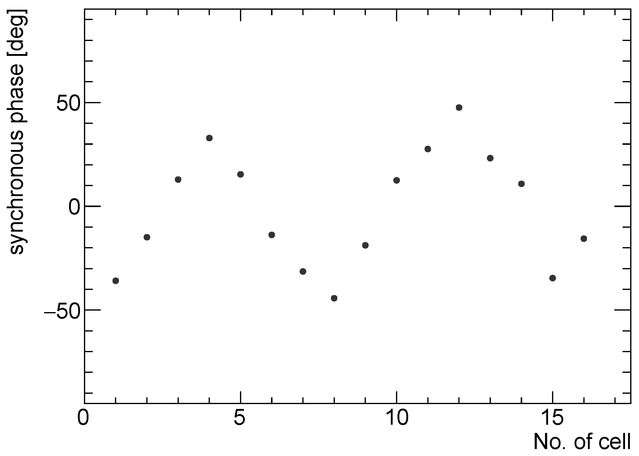
| The number of cells | 16 |
| Cavity length (m) | 1.45 |
| Unloaded quality factor | 10,910 |
| Averaged accelerating field (MV/m) | 3.6 |
| Maximum surface field (MV/m) | 35.4 (2.0 ) |
| Nominal power (kW) | 310 |
Disclaimer/Publisher’s Note: The statements, opinions and data contained in all publications are solely those of the individual author(s) and contributor(s) and not of MDPI and/or the editor(s). MDPI and/or the editor(s) disclaim responsibility for any injury to people or property resulting from any ideas, methods, instructions or products referred to in the content. |
© 2023 by the authors. Licensee MDPI, Basel, Switzerland. This article is an open access article distributed under the terms and conditions of the Creative Commons Attribution (CC BY) license (https://creativecommons.org/licenses/by/4.0/).
Share and Cite
Nakazawa, Y.; Cicek, E.; Ego, H.; Fukao, Y.; Futatsukawa, K.; Hasegawa, K.; Iijima, T.; Iinuma, H.; Inami, K.; Ishida, K.; et al. Interdigital H-Mode Drift Tube Linear Accelerator for a Muon Linear Accelerator. Phys. Sci. Forum 2023, 8, 20. https://doi.org/10.3390/psf2023008020
Nakazawa Y, Cicek E, Ego H, Fukao Y, Futatsukawa K, Hasegawa K, Iijima T, Iinuma H, Inami K, Ishida K, et al. Interdigital H-Mode Drift Tube Linear Accelerator for a Muon Linear Accelerator. Physical Sciences Forum. 2023; 8(1):20. https://doi.org/10.3390/psf2023008020
Chicago/Turabian StyleNakazawa, Yuga, Ersin Cicek, Hiroyasu Ego, Yoshinori Fukao, Kenta Futatsukawa, Kazuo Hasegawa, Toru Iijima, Hiromi Iinuma, Kenji Inami, Katsuhiko Ishida, and et al. 2023. "Interdigital H-Mode Drift Tube Linear Accelerator for a Muon Linear Accelerator" Physical Sciences Forum 8, no. 1: 20. https://doi.org/10.3390/psf2023008020