Article

Ferroelectric and Dielectric Properties of Strontium Titanate Doped with Barium

1
Physics Department, Faculty of Science, Tanta University, Tanta 31527, Egypt
2
NANOTECH Center, Ural Federal University, 620002 Ekaterinburg, Russia
3
Institute of Metallurgy of the Ural Branch of the Russian Academy of Sciences, 620016 Ekaterinburg, Russia
*
Author to whom correspondence should be addressed.
Magnetism 2021, 1(1), 22-36; https://doi.org/10.3390/magnetism1010003
Submission received: 4 September 2021 / Revised: 30 October 2021 / Accepted: 1 November 2021 / Published: 11 November 2021
(This article belongs to the Special Issue Magnetocaloric Effect: Theory and Experiment in Concert)

Abstract

:
Ferroelectric samples Sr1−xBaxTiO3 (BST), where x = 0, 0.2, 0.4, 0.6, 0.8 and 1, were prepared using the tartrate precursor method and annealed at 1200 °C for 2 h. X-ray diffraction, “XRD”, pattern analysis verified the structure phase. The crystallite size of the SrTiO3 phase was calculated to be 83.6 nm, and for the TiO2 phase it was 72.25 nm. The TEM images showed that the crystallites were agglomerated, due to their nanosize nature. The AC resistivity was measured as temperature dependence with different frequencies 1 kHz and 10 kHz. The resistivity was decreased by raising the frequency. The dielectric properties were measured as the temperature dependence at two frequencies, 1 kHz and 10 kHz. The maximum amount of dielectric constant corresponded to the Curie temperature and the transformation from ferroelectric to paraelectric at 1 kHz was sharp at 10 kHz. Polarization–electric field hysteresis loops for BST samples were measured using a Sawer–Tawer modified circuit. It was shown that the polarization decreased with increasing temperature for all samples.

1. Introduction

Ferroelectric materials are widespread materials for progressive technology. Ferroelectric materials are arduous elements used in piezoelectric equipment and sequenced missions, such as sensing and actuation. They have featured behaviors, such as switchable macroscopic polarization, that have attracted prolonged interest for purposes in nonvolatile memories, micro-electromechanical systems, nonlinear optics and sensors. Additionally, in nano ranges, the ferroelectric structure has demonstrated completely different features from materials with a bulk structure. The dependence of ferroelectric characteristics on grain size is due to its electrical properties [1]. BaSrTiO3 (BST) is the most popular ferroelectric oxide in the perovskite ABO3 structure. Convenient insulating BST, which has a high dielectric constant, is suitable for use in capacitors and is preferred in several devices, such as high-speed random-access memories, dynamic random-access memories, piezoelectric transducers, wireless communication devices and pyroelectric elements [1,2].
BaSrTiO3 (BST) has attracted considerable research interest, due to its strong dielectric nonlinearity under a bias electric field and linearly adjustable Curie temperature with the (Sr) content [3,4,5]. The extension of (Sr) into BaTiO3 changes the Curie point to make BST a paraelectric material at room temperature, offering a high dielectric constant and low leakage current. Previous studies [6,7,8,9,10,11,12,13,14,15] have explained different techniques for obtaining BST.
Ying Yao et al. [13] have scrutinized the sintering and (ε) of BST. The structure becomes more homogeneous through sintering operations, involving the inter-diffusion of ions. This can be deduced from dielectric measurements, both phase transitions for BST and for BaTi4O9. Moreover, the neoteric structure transition for BaTi4O9 greatly affects the (ε) properties in main-phase BST, as well as for BT ceramics. K.A. Razak et al. [14,15] studied BST generated by a hydrothermal reaction, forming a two-phase structure. The two phases have diverse grain size after sintering, in which grain size grows with the raised Ba content. It can observed that a clear increase in dielectric properties by adding Ba content is affected by the electronic state of materials and grain sizes. Nisha D. Patel et al. [16,17] prepared (BST) with different Sr/Ba ratios. It is known that crystallinity reduces with an increase in Sr content.
The present work focuses on the synthesis of BaxSr1-xTiO3 through the tartrate precursor method, and a comparative study of the structural, morphological, AC electrical resistivity properties and ferroelectric hysteresis measurements was carried out. The novelty of this work is the success of preparing the ferroelectric BST using the tartrate precursor method. It was noticed that d33 factor increased by increasing Ba ions to control some properties of SrTiO3.

2. Materials and Methods

A ferroelectric BST (x = 0, 0.2, 0.4, 0.6, 0.8 and 1) system was prepared by the tartrate precursor method [18]. Figure 1 shows the tartrate precursor method. The powder was collected and heat-treated at 1200 °C for 2 h. The Rietveld refinement of XRD patterns was examined using COD on the website http://www.crystallography.net/ (accessed on 23 April 2021) to match and fit, using the software Fullprof and Vesta. The microstructure was analyzed using a TEM model (JEOL1010). For AC resistance studies, the samples were pressed in pellet form, then measured by using RLC Bridge (BM591) to measure (ε) and dielectric loss (tanδ) of all the samples at temperature range from −70 to 250 °C. P–E hysteresis loops were measured with a modified Sawyer–Tower circuit, as shown in Figure 2 [19]. For hysteresis measurements, the sample was polarized at 2 kV for 2 h at RT, and the hysteresis loop was shown using an oscilloscope.

3. Results

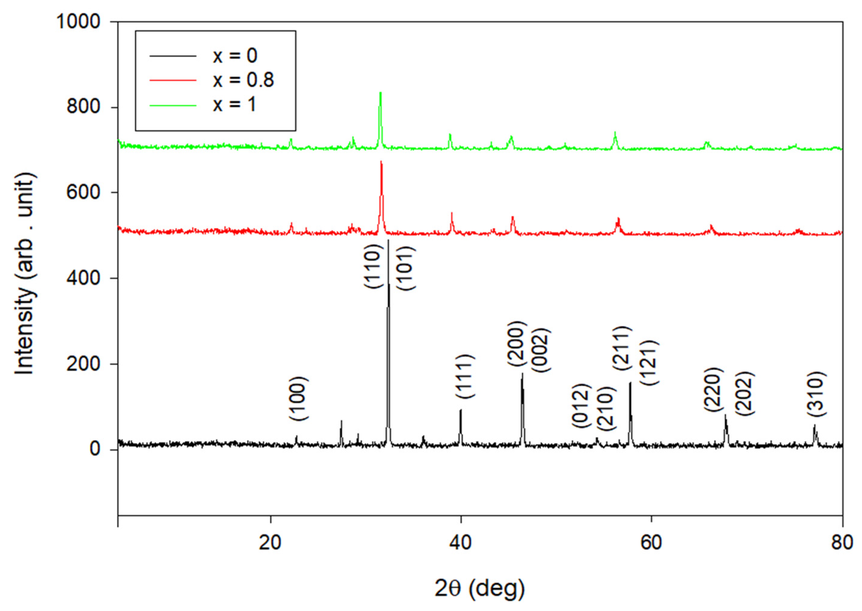
3.1. Rietveld Refined of X-ray Patterns

Figure 3 shows the XRD patterns of the structure BST at x = 0, 0.8 and 1. It is observed that the major phase is BST with the presence of some peaks at 2θ = 27.4° which may be due to the presence of small amounts of Sr3Ti2O7 and the peak at 2θ = 29.14° due to the presence of BaTi4O9. The peak at 2θ = 36.15° can be attributed to the Sr(NO3)2, and at higher concentrations of barium, it disappears [20,21,22]. The intensity of these diffraction peaks decrease with increasing Ba, and with higher contents, the pattern confirms a single tetragonal phase of BST [23]. The XRD pattern is mentioned in detail in a previous paper [24,25,26].
From the Rietveld refinement for SrTiO3, the presence of two phases, TiO2 and SrTiO3, can be proposed. The TiO2 phase with a space group of P42/mnm has a tetragonal structure with weight fraction of 27.44%, and the SrTiO3 phase with a space group of Pm-3m has a cubic structure with weight fraction of 72.56%. Both were confirmed from XRD analyses. The analyzed Rietveld refinement values of both phases are given in Table 1, with lattice parameter a = b = c for cubic SrTiO3 and a = b # c for tetragonal TiO2. The crystallite size of the SrTiO3 phase was calculated to be 83.6 nm, and 72.25 nm for the TiO2 phase [27,28]. Figure 4a shows a ball-and-stick model for the SrTiO3 phase (cubic phase) drawn using crystallographic information with FullProf and Vesta software. It is shown in Figure 4 (a) that Sr ions are present in the body center of the unit cell with coordination (0.5, 0.5, 0.5), whereas Ti ions are located at the corners with coordination (0, 0, 0) and O ions are located at the edge centers with coordination (0.5, 0, 0). as given in Table 2.
The Rietveld analysis for the sample where x = 0.8 showed three phases: a tetragonal phase with space group P4mm and weight fraction 60.53%; the second phase (hexagonal phase) was BaTiO3 with space group P63/mmc and weight fraction 39.37%; and the last phase was Sr2, which has a cubic structure with space group Im-3m and weight fraction 0.1%. The density, crystallite size and lattice parameters of these three phases are given in Table 1.
The Rietveld refinements of lattice constant agree with the experimental value previously reported in [29,30] for the first phase at x = 0.8, which demonstrated that the lattice parameter was 3.98 Å. Figure 4b shows a ball-and-stick model for the phase at x = 0.8 (tetragonal phase). This was drawn using crystallographic information with FullProf and Vesta software. The ball-and-stick model shows that Ti ions are present in the body center of the unit cell with coordination (0.5, 0.5, 0.5), and both Sr and Ba ions are located at corners of the unit cell with coordination (0, 0, 0) and O are at the face center, as given in Table 2.
The last sample where x = 1 (BaTiO3) contains two phases: the tetragonal phase with space group P4mm and a weight fraction of 71.05%, and the hexagonal with space group P63/mmc and with a weight fraction of 28.95%. The density, crystallite size and lattice parameters of these two phases are given in Table 1. Figure 4c show ball-and-stick model for the BaTiO3 phase (tetragonal phase). It was drawn using crystallographic information with FullProf and Vesta software. The ball-and-stick model shows that Ti ions were present in the body center of the unit cell with coordination (0.5, 0.5, 0.5), and Ba ions were located at the corner center with coordination (0, 0, 0), as given in Table 2.

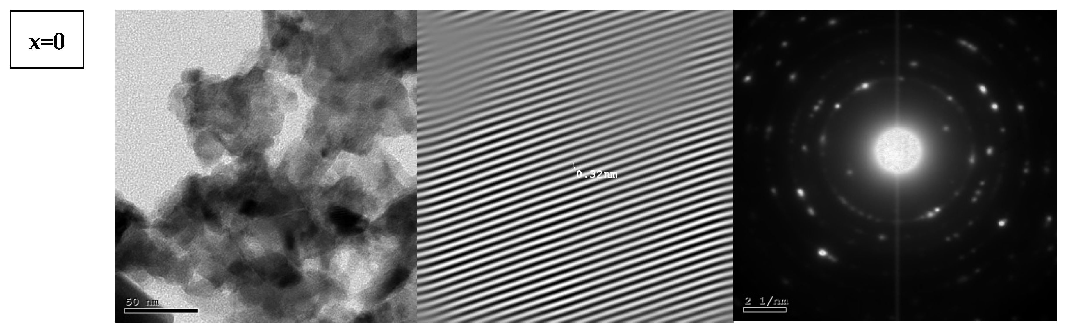
3.2. High-Resolution Transmission Electron Microscopy (HR-TEM)

TEM micrographs of BST samples for x = 0, 0.8 and 1 with electron diffraction patterns and high-resolution TEM images are shown in Figure 5. The TEM images show that the crystallites were agglomerated due to their nanosize nature, with an average crystallite size ranging from 20.2 nm to 48.02 nm belonging to a tetragonal phase which iwas confirmed by XRD, whereas the crystallite size in both XRD results and TEM results were nearly the same as those given in Table 3; BST had lower values than SrTiO3. The high-resolution TEM images show the lattice planes with an inter-planar distance d = 0.32 nm, corresponding to the diffraction plane (100) which clearly appeared in the diffraction pattern at 2θ = 22.72°. The electron diffraction pattern was also consistent with the tetragonal lattice structure which was observed by XRD.
The high-resolution TEM images in Figure 4B for samples x = 0.8 and 1 show the interference of two planes (101) and (100) with d-spacing 0.27 nm and 0.32 nm, which appeared in the XRD pattern at 2θ = 32.29° and 22.72°, respectively.
Figure 4C shows the selected area electron diffraction patterns for samples x = 0, 0.8 and 1. The crystalline features of the nanopolycrystalline material could be confirmed from the electron diffraction patterns, which contained a set of halo rings with a uniform center [31,32,33]. The crystalline lattice planes for the different circles, corresponding to different peaks of the tetragonal phase, are defined as (100), (110), (111), (200) and (210), which appeared in the XRD pattern and showed a comparison between the electron diffraction pattern and X-ray diffraction pattern [34].

3.3. AC Electrical Resistivity

The AC resistivity for BST related to reciprocal temperature is shown in Figure 6, where Figure 6a is at a frequency of 1 kHz and Figure 6b is at 10 kHz. Notably, the resistivity reduced by raising the frequency, which might have been due to the high relaxation time of charge carriers occurring at low frequency, which resulted in high resistivity. Moreover, as the frequency increased, more charge carriers could respond easily to the external electric field, resulting in lower resistivity.
The decrease in AC resistivity with increasing temperature was observed in the high-temperature zone, discerning that the mobility of charge carriers are thermally activated, leading to the decrease in resistivity. The conduction process in our samples is attributed to the hopping electron between Ti3+ and Ti4+ when an electric field is applied [35]. The addition of a barium ion obstructs the hopping electrons, which raise the resistivity for all samples compared with the SrTiO3 sample. The total AC resistivity can be given from the equation [36]:
ρ A C = ρ D C   + A   ω n ,
where A is a constant and n is a dimensionless parameter. The values of n were calculated using the formula n = ln ρ ln ω [37] and demonstrated in Figure 7. It shows that the value of n decreased in the high temperature region and increased with the increasing barium content, indicating the increased disorder in the samples. The samples became more frequency-dependent and sensitive to any frequency variation when the barium content increased.

3.4. Dielectric Constant with Temperature Properties

Dielectric constant (ε) and dielectric loss at two fixed frequencies of 1 kHz and 10 kHz for BST samples at different temperatures are illustrated in Figure 8. The dielectric constant increased slightly with increasing temperature and exhibited a peak at around room temperature. This peak at the Curie point was due to the transition from the ferroelectric to paraelectric phase, and originated from the presence of the BaTi4O9 phase. This phase appeared in the XRD patterns, which confirmed our hypothesis. The ultimate (ε) value appeared at Curie temperature [38]. Encouragingly, there was compatibility between our results and the result obtained in a previous study [39].
The dielectric constant results show that the sharp increase in dielectric constant varied from 241 K to 300 K for x = 0 and x = 0.8, respectively. The dielectric peak become broad and intense by raising the Ba content up to x = 0.6. The Curie temperature for pure barium titanate gave a transition temperature (Curie temperature) of around 415 K and another small peak at 287 K due to the minor BaTi4O9 phase. The evident rise of (ε) near room temperature resulted from the impure BaTi4O9 phase, which exhibited abnormal (ε) and (tan δ) and greatly influenced the dielectric properties of the major BST phase. The disappearance of the second peak (at TC = 415 K) for other samples indicated that the minor phase plays a dominant role in the (ε) features of these samples. The phase transition for BaTi4O9 was shifted to lower temperatures by increasing the barium content. As shown in Figure 8, the broad peak appearing at around 415 K corresponded to the Curie temperature for the barium titanate, whereas the small peak at around 287 K was related to the BaTi4O9 phase.
Usually, the Curie temperature of around 415 K for BaTiO3 is due to alterations in the structure from the tetragonal to cubic phase. Furthermore, the phase transition around RT is related to the transition from an orthorhombic to tetragonal structural. From previous work [40], it could be concluded that the phase changed from ferroelectric to paraelectric, and the dielectric constant of BST at x = 0.2, 0.4 increased at around 288 K, whereas in our work, it was at about 281 K.
Notably, the value of the dielectric constant at 1 kHz was larger than that at 10 kHz. Thus, we deduced that the dielectric properties of BST are greatly affected by the barium and strontium contents.
All phases in the BT sample were in the rhombohedra phase at T < 183 K, which was outside our temperature range (203 K–523 K). The second was the orthorhombic phase from 183 K to 278 K, which appeared at 270 K, as illustrated in Figure 9. The third phase was the tetragonal phase from 278 K to 450 K, which was the ferroelectric phase. The fourth phase was cubic at temperatures above 450 K, and as the paraelectric phase. The four phases are illustrated in Table 4. The broad peak around 450 K, which was the transition from ferroelectric to paraelectric, was characteristic of relaxor phase transition.

3.5. The Ferroelectric Hysteresis-Loop of BST Samples

Figure 10 represents ferroelectric hysteresis loops for BST samples at 30 °C. It can be observed that the inclination of hysteresis loop increased with increasing the barium content. The x = 0.6 sample had the highest inclination, and the x = 0.4 sample had the minimum inclination. The increase in polarization for the x = 0.6 sample was due to the increase in 180° and 90° domains in the trend of the applied field. From the results of the tan δ, it was found that the x = 0.6 sample had the highest value of dielectric loss, confirming the present results of the dielectric hysteresis loop which indicated that the x = 0.6 sample had the highest polarization.
The remnant polarization as well as the coercive electric field simultaneously decreased by increasing the Ba content, suggesting that our ferroelectric samples were ferroelectric relaxors with slim hysteresis loops, as shown in Figure 10.
Figure 10 represents the P–T hysteresis loops of BST samples measured from RT ≈ 45 °C to 160 °C. In general, in all compositions, the hysteresis loops became slim and narrow as the temperature increased and nearly closed to certain temperature around TC, as given in Table 5, due to the transformation from ferroelectric to paraelectric states. At this temperature the polarization of material dropped and the relationship between the electric field and polarization became linear without hysteresis. This trend is reflected by the decrease in polarization as the temperature increased, as shown in Figure 11.
The polarization decreased with increasing sample temperature, as shown in Figure 10, due to the random orientation which occurred in the domains under the effect of thermal agitation, and the polarization become temperature-independent at high temperature [40,41].

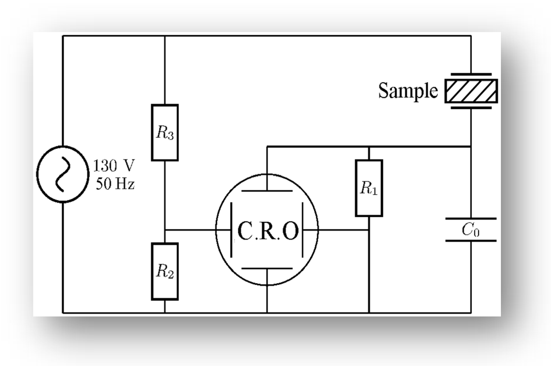
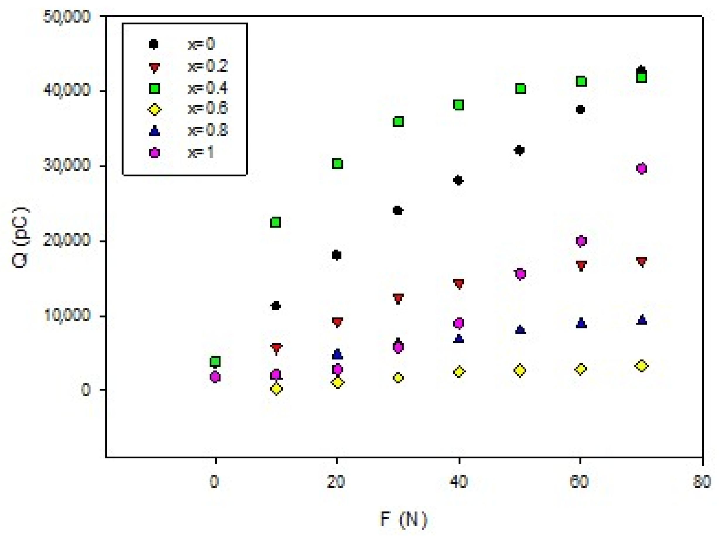
3.6. Piezoelectric Coefficient of BST Samples

The effects of Ba content on the piezoelectric charge (Q33) at different loading stresses are shown in Figure 12. It can observed from the Q33 of the polarized sample that synthesis by the tartrate method increased by increasing the load stress. From Figure 12, we measured the d33 of the different samples by taking the slope of the linear part in the units of pC/N. As a result of the orientation of 90° domains and 180° domains, the piezoelectric response was observed in BST samples. Table 6 represents the d33 with different Ba concentrations. It was observed that the x = 0.4 sample had the highest d33 compared with other samples. The increase in d33 for the x = 0.4 sample may have been due to the presence of a large number of 90° domains, which gave higher values of d33 under high mechanical stress. From these results, we can conclude that the x = 0.4 sample is suitable for piezoelectric technical applications and sensors.
The main factor that affects the d33 is domain wall motion, which increases the polarization, and hence increases the d33 and the generated piezoelectric charge.
It is shown in Table 6 that the samples with smaller grain sizes had higher values of d33. The small area of the grain increased the domain wall mobility, giving rise to high d33 under applied stress. The higher value of d33 was obtained when the grain size was equal to 0.15 μm. It is important to state that the piezoelectric features and the grain size are strongly affected by the method of preparation and the type of raw material [1,24,25]. The x = 0.4 sample, which had the smallest grain size and the narrowest grain width, exhibited more activity of the 90° domain wall and enhanced the piezoelectric properties [26]. This mechanism sufficiently explains the high value of the piezoelectric constant at x = 0.4. The value of d33 for sample x = 0.8 with formula Sr0.2 Ba0.8 TiO3 was 178. The value of 2653 pC / N is higher compared with another study experimenting with the same concentration, where x = 0.8 was 160 pC / N [22]. We can consider that x = 0.4 is the decisive grain size at which the piezoelectric constant has a higher value. At the higher Ba content of x = 0.4, the piezoelectric constant decreased after increasing the grain size and reached minimum at x = 1, where the grain size was equal to 0.32 μm.

4. Conclusions

The BST powders with x = 0, 0.2, 0.4, 0.6, 0.8 and 1 were prepared with the tartrate precursor method. For higher barium contents, the X-ray diffraction patterns indicated a single tetragonal phase of BST. From the TEM images, it was observed that the crystallites agglomerated due to their nanosize nature. The resistivity decreased with increasing the frequency for all samples. The addition of barium ions obstructed the hopping electrons, leading to increases in resistivity for all samples compared with the SrTiO3 sample. The dielectric peak became broad and intense after increasing the barium content up to x = 0.6. The x = 0.4 sample had minimum inclination compared with other samples, and the polarization decreased with increasing the temperature for all samples. The x = 0.4 sample had the highest d33 compared with other samples.

Author Contributions

A.M.H.: Conceptualization, Resources, Visualization, Writing—Review and Editing. M.M.: Investigation, Formal Analysis, Visualization, Writing. I.W.: Visualization, Writing—Original Draft Preparation, Writing—Review and Editing, O.H.: Investigation, Visualization, Writing—Original Draft Preparation, Supervision, Funding Acquisition. B.S.: Investigation, Data Analysis, Visualization. All authors have read and agreed to the published version of the manuscript.

Funding

I.W. thank the Minobrnauki research project FEUZ-2020-0059 for support.

Data Availability Statement

The data that support the findings of this study are available on request from the corresponding author.

Conflicts of Interest

The authors declare no conflict of interest.

References

  1. Mudinepalli, V.R.; Feng, L.; Lin, W.; Murty, B.S. Effect of grain size on dielectric and ferroelectric properties of nanostructured Ba0.8Sr0.2TiO3 ceramics. J. Adv. Ceram. 2015, 4, 46–53. [Google Scholar] [CrossRef] [Green Version]
  2. Xiao-Fei, Z.; Qing, X.; Yu-Heng, H.; Han-Xing, L.; Duan-Ping, H.; Feng, Z. Low-temperature synthesis of superfine barium strontium titanate powder by the citrate method. Ceram. Int. 2010, 3, 1405–1409. [Google Scholar]
  3. Lee, J.H.; Rhee, S.W.J. Chemical Vapor Deposition of Barium Strontium Titanate Films with Direct Liquid Injection of Single-Mixture Solution. Electrochem. Soc. 1999, 146, 3783. [Google Scholar] [CrossRef] [Green Version]
  4. Kuzmina, N.; Malkerova, I.; Alikhanyan, A.; Tsymbarenko, D.; Lyssenko, K.; Kreinin, O.; Shuster, G.; Lakin, A.; Zolotoyabko, E. Novel Low Melting Point Barium and Strontium Precursors for the MOCVD Growth of Barium-Strontium-Titanate Films. Chem. Vap. Depos. 2009, 15, 342. [Google Scholar] [CrossRef]
  5. Di, W.; Aidong, L.; Zhiguo, L.; Huiqin, L.; Chuan, Z.G.; Xiaoyong, L.; Hong, W.; Min, W.; Peng, L.; Naiben, M. Fabrication and electrical properties of sol-gel derived (BaSr)TiO3 thin films with metallic LaNiO3 electrode. Thin Solid Films. 1998, 336, 172. [Google Scholar]
  6. Nam, S.; Cho, N.; Kim, H. Characterization of SrTiO3 thin films prepared by RF magnetron sputtering. J. Phys. D Appl. Phys. 1992, 25, 727. [Google Scholar] [CrossRef]
  7. Remiens, D.; Yang, L.; Ponchel, F.; Le gier, J.F.; Chateigner, D.; Wang, G.; Dong, X. X-ray combined analysis of fiber-textured and epitaxial Ba(Sr,Ti)O3 thin films deposited by radio frequency sputtering. J. Appl. Phys. 2011, 109, 114106. [Google Scholar] [CrossRef]
  8. Ponchel, F.; Midy, J.; Le gier, J.F.; Soyer, C.; Re miens, D.; Lasri, T.; Guéguan, G. Dielectric microwave characterizations of (Ba,Sr)TiO3 film deposited on high resistivity silicon substrate: Analysis by two-dimensional tangential finite element method. J. Appl. Phys. 2010, 107, 054112. [Google Scholar] [CrossRef]
  9. Abdel-Motaleb, I.; Shetty, N.; Leedy, K.; Cortez, R. Investigation of the drain current shift in ZnO thin film transistors. J. Appl. Phys. 2011, 109, 014503. [Google Scholar] [CrossRef]
  10. Leach, J.H.; Liu, H.; Avrutin, V.; Rowe, E.; Ozgur, U.; Morkoc, H.; Song, Y.Y.; Wu, M. Electrically and magnetically tunable phase shifters based on a barium strontium titanate-yttrium iron garnet layered structure. J. Appl. Phys. 2010, 108, 064106. [Google Scholar] [CrossRef] [Green Version]
  11. Ibrahim, A.-M.; Bhavya, A.; Kevin, L.; Rebecca, C. Oxygen effects on barium strontium titanate morphology and MOS device performance. Mater. Lett. 2013, 92, 389–392. [Google Scholar]
  12. Mahani, R.M.; Battisha, I.K.; Aly, M.; Abou-Hamad, A.B. Structure and dielectric behavior of nano-structure ferroelectric BaxSr1−xTiO3 prepared by sol–gel method. J. Alloys Compd. 2010, 508, 354. [Google Scholar] [CrossRef]
  13. Ying, Y.; Shuangbin, L.; Yongzhong, J.; Shaolei, X. Microstructure and dielectric properties of BaxSr1−xTiO3 ceramics prepared by direct current arc discharge technique. J. Alloys Compd. 2015, 651, 273–277. [Google Scholar]
  14. Razak, K.A.; Asadov, A.; Yoo, J.; Haemmerle, E.; Gao, W. Structural and dielectric properties of barium strontium titanate produced by high temperature hydrothermal method. J. Alloys Compd. 2008, 449, 19–23. [Google Scholar] [CrossRef]
  15. Arrasheed, E.; Meaz, T.; Shalaby, R.; Salem, B.; Hemeda, O.; Henaish, A. Rietveld refinement, cation distribution, morphological and magnetic study of NiAlxFe2-xO4 nanoparticles. Appl. Phys. A 2021, 127, 221. [Google Scholar] [CrossRef]
  16. Patel, N.D.; Mangrola, M.H.; Soni, K.G.; Joshi, V.G. Structural and Electrical Properties of Nanocrystalline Barium Strontium Titanate. Mater. Today Proc. 2017, 4, 3842–3851. [Google Scholar] [CrossRef]
  17. Hemeda, O.M.; Salem, B.I.; Mostafa, M. Structural and electric properties of strontium barium titanate prepared by tartrate precursor method. Eur. Phys. J. Plus 2020, 135, 46. [Google Scholar] [CrossRef]
  18. Henaish, A.M.A. Physical and Spectral Studies of Mg-Zn Ferrite Prepared Using Different Methods. Arab J. Nuc. Sci. Appl. 2019, 53, 9–18. [Google Scholar]
  19. Ioachim, A.; Toacsan, M.I.; Banciu, M.G.; Nedelcu, L.; Vasiliu, F.; Alexandru, H.V.; Berbecaru, C.; Stoica, G. Barium strontium titanate- based perovskite materials for microwave applications. Solid State Chem. 2007, 35, 513–520. [Google Scholar] [CrossRef]
  20. Brankovic, G.; Brankovic, Z.; Goes, M.S.; Paiva-Santos, C.O.; Cilense, M.; Varela, J.A.; Longo, E. Barium strontium titanate powders prepared by spray pyrolysis. Mater. Sci. Eng. B 2005, 122, 140–144. [Google Scholar] [CrossRef]
  21. Chen, J.; Che, M.C.; Yan, F. Synthesis of barium strontium titanate nanopowders by microwave hydrothermal method. Adv. Appl. Ceram. 2015, 114, 344–349. [Google Scholar] [CrossRef]
  22. Henaish, A.M.A.; Hemeda, O.M.; Dorgham, A.M.; Hamad, M.A. Characterization of excessive Sm3+ containing barium titanate prepared by tartrate precursor method. J. Mater. Res. Technol. 2020, 9, 15214–15221. [Google Scholar] [CrossRef]
  23. Hemeda, O.M.; Mostafa, N.Y.; Elkader, O.H.A.; Hemeda, D.M.; Tawfik, A.; Mostafa, M. Electrical and morphological properties of magnetocaloric nano ZnNi ferrite. J. Magn. Magn. Mater. 2015, 394, 96–104. [Google Scholar] [CrossRef]
  24. Pinjari, R.K.; Burange, N.M.; Aldar, B.A. Structural and Electrical Analysis of Strontium Substituted Barium Titanate. Int. J. Eng. Res. Technol. (IJERT) 2014, 3, 209–213. [Google Scholar]
  25. Jin, L.; Luo, W.; Hou, L.; Tian, Y.; Hu, Q.; Wang, L.; Zhang, L.; Lu, X.; Du, H.; Wei, X.; et al. High electric field-induced strain with ultra-low hysteresis and giant electrostrictive coefficient in barium strontium titanate lead-free ferroelectrics. J. Eur. Ceram. Soc. 2019, 39, 295–304. [Google Scholar] [CrossRef]
  26. Zheng, P.; Zhang, J.I.; Tan, Y.Q.; Wang, C.L. Grain-size effects on dielectric and piezoelectric properties of poled BaTiO3 ceramics. Acta Mater. 2012, 60, 5022–5030. [Google Scholar] [CrossRef]
  27. Huan, Y.U.; Wang, X.; Fang, J.; Li, L. Grain-size dependence of piezoelectric properties in thermally annealed BaTiO3 ceramics. J. Am. Ceram. Soc. 2013, 96, 3369–3371. [Google Scholar] [CrossRef]
  28. Zhang, Q.M.; Wang, H.; Kim, N.; Cross, L.E. Direct evaluation of domain-wall and intrinsic contributions to the dielectric and piezoelectric response and their temperature dependence on lead zirconate-titanate ceramics. J. Appl. Phys. 1994, 75, 454–456. [Google Scholar] [CrossRef]
  29. Hongwei, C.; Chuanren, Y.; Chunlin, F.; Li, Z.; Zhiqiang, G. The size effect of Ba0.6Sr0.4TiO3 thin films on the ferroelectric properties. Appl. Surf. Sci. 2006, 252, 4171–4177. [Google Scholar]
  30. Henaish, A.M.A.; Mostafa, M.; Salem, B.I.; Hemeda, O.M. Improvement of magnetic and dielectric properties of magnetoelectric BST-NCZMF nano-composite. Phase Transitions 2020, 93, 470–490. [Google Scholar] [CrossRef]
  31. Damjanovic, D.; Klein, N.; Li, J.; Porokhonskyy, V. What Can Be Expected From Lead-Free Piezoelectric Materials? Funct. Mater. Lett. 2010, 3, 5–13. [Google Scholar] [CrossRef]
  32. Li, F.; Wang, L.; Jin, L.; Lin, D.; Li, J.; Li, Z.; Xu, Z.; Zhang, S. Piezoelectric activity in perovskite ferroelectric crystals. IEEE Trans. Ultrason. Ferroelectr. Freq. Control. 2015, 62, 18–32. [Google Scholar] [CrossRef] [PubMed]
  33. Zhang, H.; Xu, P.; Patterson, E.; Zang, J.; Jiang, S.; Rödel, J. Preparation and enhanced electrical properties of grain-oriented (Bi1/2Na1/2)TiO3-based lead-free incipient piezoceramics. J. Eur. Ceram. Soc. 2015, 35, 2501–2512. [Google Scholar] [CrossRef]
  34. Fan, P.; Zhang, Y.; Zhang, Q.; Xie, B.; Zhu, Y.; Mawat, M.A.; Ma, W.; Liu, K.; Xiao, J.; Zhang, H. Large strain with low hysteresis in Bi4Ti3O12 modified Bi1/2(Na0.82K0.18)1/2TiO3 lead-free piezoceramics. J. Eur. Ceram. Soc. 2018, 38, 4404–4413. [Google Scholar] [CrossRef]
  35. Hemeda, O.M.; Eid, M.E.A.; Sharshar, T.; Ellabany, H.M.; Henaish, A.M.A. Synthesis of nanometer-sized PbZrxTi1-xO3 for gamma-ray attenuation. J. Phys. Chem. Solids. 2021, 148, 109688. [Google Scholar] [CrossRef]
  36. Salem, B.I.; Hemeda, O.M.; Mostafa, M.; Henaish, A.M.A. Electric and ferroelectric properties of high-energy ball milling-assisted (1 − x) Sr0.2Ba0.8TiO3 + (x) Ni0.1Cu0.2Zn0.15Mg0.55Fe2O4 composite. J. Mater. Sci. Mater. Electron. 2020, 31, 18673–18682. [Google Scholar] [CrossRef]
  37. Jo, W.; Dittmer, R.; Acosta, M.; Zang, J.; Groh, C.; Sapper, E.; Wang, K.; Rödel, J. Giant electric-field-induced strains in lead-free ceramics for actuator applications – status and perspective. J. Electroceram. 2012, 29, 71–93. [Google Scholar] [CrossRef]
  38. Malik, R.A.; Hussain, A.; Maqbool, A.; Zaman, A.; Song, T.K.; Kim, W.-J.; Kim, M.-H. Giant strain, thermally-stable high energy storage properties and structural evolution of Bi-based lead-free piezoceramics. J. Alloys Compd. 2016, 682, 302–310. [Google Scholar] [CrossRef]
  39. Lv, J.; Gao, W.; Li, J.; Li, T.; Long, C.; Lou, X.; Wu, J. Large strain and strain memory effect in bismuth ferrite lead-free ceramics. J. Mater. Chem. C 2017, 5, 9528–9533. [Google Scholar] [CrossRef]
  40. Cross, L.E.; Jang, S.J.; Newnham, R.E.; Nomura, S.; Uchino, K. Large electrostrictive effects in relaxor ferroelectrics. Ferroelectrics 1980, 23, 187–191. [Google Scholar] [CrossRef]
  41. Tian, Y.; Jin, L.; Zhang, H.; Xu, Z.; Wei, X.; Politova, E.D.; Stefanovich, S.Y.; Tarakina, N.V.; Abrahams, I.; Yan, H. High energy density in silver niobate ceramics. J. Mater. Chem. A 2016, 4, 17279–17287. [Google Scholar] [CrossRef]
Figure 1. The tartrate precursor method.
Magnetism 01 00003 g001
Figure 2. The Sawyer–Tawer circuit.
Magnetism 01 00003 g002
Figure 3. XRD of BST with x = 0, 0.2, 0.8 and 1.
Magnetism 01 00003 g003
Figure 4. The Rietveld-refined XRD patterns (left) and Rietveld refinement diffraction planes (right) of (a) SrTiO3, (b) Sr0.2Ba0.8TiO3 and (c) BaTiO3 structures.
Magnetism 01 00003 g004aMagnetism 01 00003 g004b
Figure 5. (A) HRTEM images, (B) the fringing spacing and (C) selected area electron diffraction pattern for BST with x = 0, 0.8 and 1, respectively.
Magnetism 01 00003 g005aMagnetism 01 00003 g005b
Figure 6. The variation in ln ρ vs. 1000/ T (K−1) at different frequencies of 1 kHz (a) and 10 kHz (b) for BST samples with different Ba contents (x).
Magnetism 01 00003 g006
Figure 7. The variation of n with temperature T (K) at different frequencies of 1 kHz and 10 kHz for BST samples with different Ba contents (x).
Magnetism 01 00003 g007
Figure 8. Dielectric properties of BST (dielectric constant and dielectric loss (Tanδ)) at different frequencies, 1 kHz and 10 kHz, for different barium contents (x).
Magnetism 01 00003 g008
Figure 9. (1/Dielectric constant) “1/ε” at different frequencies, 1 kHz and 10 kHz, for different barium contents (x).
Magnetism 01 00003 g009
Figure 10. The ferroelectric hysteresis loops for piezoelectric BST samples with x = 0, 0.8 and 1: black hysteresis at room temperature and red hysteresis at different temperatures for each sample.
Magnetism 01 00003 g010
Figure 11. Polarization (P) vs. temperature T (K) of BST samples with different Ba contents.
Magnetism 01 00003 g011
Figure 12. The piezoelectric charge (Q) of BST samples for different Ba contents (x).
Magnetism 01 00003 g012
Table 1. Summary of the Rietveld analyses of XRD data for samples x = 0, 0.8 and 1.
SamplePhaseStructural ParametersCrystallographic SystemSpace
Group
Weight FractionDensity
(g/cm3)
Crystallite Size (nm)
a (Å)b (Å)c (Å)
x = 0No.1 TiO23.90533.90533.9085TetragonalP42/mnm27.44%4.45072.2548
No.2 SrTiO33.90663.90663.9066CubicPm-3m72.56%5.11183.662
x = 0.8No.1 Ba0.8Sr0.2 TiO33.98783.98783.9819TetragonalP4mm60.53%6.81939.71
No.2 BaTiO35.67085.670813.9200HexagonalP63/mmc39.37%7.8289.02
No.2 Sr23.98523.98523.9852CubicIm-3m0.10%4.59821.95
x = 1No.1 BaTiO33.989133.989134.00730TetragonalP4mm71.05%6.07322.28
No.2 BaTiO35.67815.678113.9300HexagonalP63/mmc28.95%6.07825.38
Table 2. Summary of ball-and stick-model for samples x = 0, 0.8 and 1.
xAtomAtomic Parameters
xyz
0Sr0.50.50.5
Ti000
O0.500
0.8Sr000
Ba000
Ti0.50.50.5
O0.50.50
O0.500.5
1Ba000
Ti0.50.50.5
O0.50.50
O0.500.5
Table 3. The crystallite size (D) determined from TEM and X-ray diffraction for BST samples.
SampleD (nm) from HRTEMD (nm) from XRD
x = 048.0243.40
x = 0.820.226.79
x = 137.530.11
Table 4. The four phases of BST samples.
PhaseRhombohedraOrthorhombic Tetragonal Cubic
TCout of range270450 > 450
Table 5. Curie temperature from the hysteresis of ferroelectric material (BST).
xTc from P–T Curve
(K)
Tc When Hysteresis Closed
(K)
0393433
0.2333317
0.4313298
0.6323310
0.8313314
1380388
Table 6. Piezoelectric modulus, d33, and grain size of BST samples with different Ba contents (x).
xd33 (pC/N)Grain Size (μm)
0770.71430.1905
0.2377.13950.1955
0.41144.86730.1594
0.650.52040.1699
0.8178.26530.2063
1262.56460.3125
Publisher’s Note: MDPI stays neutral with regard to jurisdictional claims in published maps and institutional affiliations.

