
Structural Systems for Tall Buildings


1
Structures Program, School of Architecture, University of Illinois at Urbana-Champaign, Champaign, IL 61820, USA
2
Department of Urban Planning and Policy, University of Illinois at Chicago, Chicago, IL 60607, USA
*
Author to whom correspondence should be addressed.
Encyclopedia 2022, 2(3), 1260-1286; https://doi.org/10.3390/encyclopedia2030085
Submission received: 30 May 2022
/
Revised: 17 June 2022
/
Accepted: 1 July 2022
/
Published: 5 July 2022
(This article belongs to the Collection Encyclopedia of Engineering)
Definition
:Structural systems for tall buildings have gone through an evolutionary process. The rigid frame became popular in the first half of the 20th century but proved to be structurally inefficient beyond a certain height of tall buildings. The invention of the tubular structure in the 1960s allowed buildings to be built taller with low material consumption. Due to the obstructive nature of the closely spaced exterior columns of framed tubes and bracings of braced tubes, the core-outrigger system gained acceptance by the architects as it allowed them to freely articulate the façade design. However, the conventional tubular structures continued to retain their use for tall buildings to a lesser degree and later underwent a resurgence in modified forms. These and other advanced tubular forms in cutting-edge structural systems developed later continue to find application in modern times. This study presents a detailed narrative of different structural systems for tall buildings that is expected to assist structural engineers and architects to collaboratively select appropriate structural systems for tall buildings.
1. Introduction and Historical Background
A principal characteristic of all tall buildings is their verticality or quality of tallness. As buildings become taller, both the gravity loads and lateral loads on them increase. One of the most fundamental attributes, which makes tall buildings of ever-growing heights physically possible, is to provide structural efficiency, i.e., using skeletal frames. Early multistory buildings were built using mainly masonry with low compressive strength. Thus, the walls carrying the weight from the upper floors needed to be very thick and heavy, so the buildings did not collapse under their own weight and thus became inefficient beyond a certain height.
The invention and application of the skeletal metal frame system, albeit in a rudimentary form, by William LeBaron Jenney for the Home Insurance Building of 1885 in Chicago, generally recognized as the first skyscraper of the world, marked the beginning of a new era for tall buildings. Although the Council on Tall Buildings and Urban Habitat (CTBUH) has defined “tall,” “supertall,” and “megatall” buildings, it has not formally defined a “skyscraper” [1]. Architectural historians have diverse opinions about what is the first skyscraper [2]. Ali and Moon offered some essential criteria for characterizing a tall building as a skyscraper and reconfirmed the Home Insurance Building as the world’s first skyscraper to satisfy these criteria [3]. The skeletal system reduced the need for a large masonry mass to support the tall buildings. It also allowed for a rudimentary curtain wall system and interior daylighting. Later, a rigid moment-resisting frame (MRF) in which the beam-to-column joints are rigidly connected was developed, making taller and lighter buildings possible. However, the taller and lighter framed buildings faced a new problem of requiring plentiful structural material to resist lateral wind forces and reduce the building’s sway. For tall buildings above 10 to 15 stories, the lateral sway due to wind forces becomes the dominant design criterion and central concern of structural performance. In the absence of a better structural system, all latter-day tall buildings, including New York’s Woolworth Building of 1913, Chrysler Building of 1930, and the Empire State Building of 1931, employed MRF and wind bracing for lateral stability as needed.
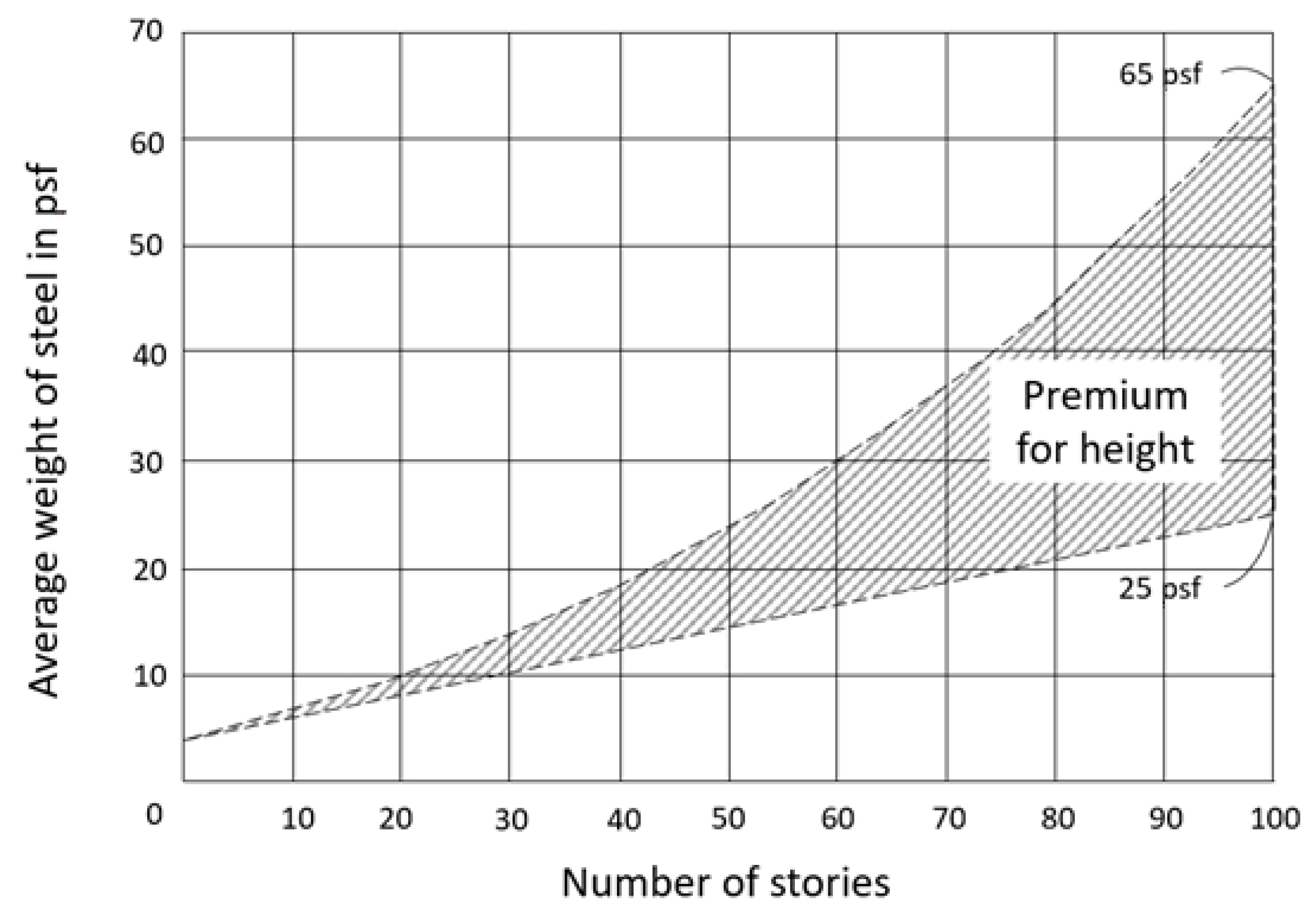
Before 1965, the design of structural systems for tall buildings was conducted utilizing the planar rigid frame by fastening together beams and columns to create a stiff structural grid to resist wind loads. Fazlur R. Khan questioned this in 1961 and tackled the entire issue of structural systems for tall buildings [4]. He realized that as buildings become taller, there is a “premium for height” to be paid due to lateral loads. The demand for the structural system increases dramatically, resulting in an exponential increase in structural material consumption [5], pp. 40–41. Khan developed his revolutionary height-based chart for structural systems in a hierarchical order for tall steel and concrete buildings [6]. This paved the way for generating a plurality of structural systems and made it possible to design and build taller and more economical buildings. Many structural and modified systems appeared on the scene to conquer the sky, defining higher skylines of cities. In addition to the tubular structure and its various modified forms that Khan developed, he also described the “ultimate structure” in which he demonstrated that maximum efficiency could be achieved by progressively relocating the exterior columns to the corners of a rectangular braced tube [7].
Beginning in the 1980s, the open-exterior tall buildings became well-liked by architects instead of the externally obstructive framed and braced tubes. During the late 1980s and 1990s, and onward, the outriggers coupling the core and widely spaced perimeter columns, creating the core-outrigger system, gained more acceptance amongst architects. Meanwhile, structural systems such as composite structures, diagrids, and variations of tube systems, also appeared or began to appear on the scene. Starting from about 2000, many other structural innovations emerged to meet the challenge of increasing the heights of supertall and megatall buildings.
Details of Evolution of Structural Systems
The logic behind the development of structural systems rests on rational pragmatism, economy of material consumption, simplicity and elegance, and concern for constructability. In discussing the progression of structural systems for tall buildings, metamorphosis can be observed among them at different times. In the beginning, a tall building was of masonry construction occasionally supplemented with metal elements. This was followed by skeletal construction with the 10-story Home Insurance Building of 1885, marking the commencement of the metal frame skyscraper structure. In 1903, the 15-story Ingalls Building in Cincinnati, Ohio, designed and built by A.O. Elzner, was the first reinforced concrete high-rise building. The first detailed study of the “Effects of Scale” was carried out by Myron Goldsmith in a master’s thesis at the Illinois Institute of Technology (IIT), Chicago, in 1953, under the supervision of Mies van der Rohe [8]. A new era set in for taller and cost-effective buildings when during 1961–1969, the frame-shear interaction and, more remarkably, the tube systems were developed by Fazlur R. Khan. During 1966–1969, the groundbreaking height-based structural systems charts for tall steel and concrete buildings were developed by Khan. The 38-story reinforced concrete Brunswick Building using the shear wall-frame interaction principle and the 42-story reinforced concrete Dewitt-Chestnut Apartment Building using the framed tube concept, both located in Chicago and built in 1965, were engineered by Khan. Although the Brunswick Building resembles a tube-in-tube structure, it was designed, without regard for any tubular action, as a shear wall-frame interaction system, where the exterior frames parallel to wind direction were designed for shear wracking, and the three-dimensional behavior of the exterior frames was also captured by cantilever analysis [5], pp. 86–87. Meanwhile, in 1964, the 47-story reinforced concrete Place Victoria building in Montreal by Pier L. Nervi was built as the first application of the core-outrigger concept.
Completed in 1970, the 100-story John Hancock Center in Chicago was designed by Fazlur R. Khan as the first steel braced tube structure. The 20-story Control Data Center in Houston, TX, designed by Khan was the first modern steel-concrete composite building built in 1971. In 1973, the World Trade Center in New York City (destroyed in 2001) was the first steel-framed tube structure designed by Leslie Robertson. Shortly after, the 109-story Sears Tower in Chicago was built in 1974 and engineered by Khan as the first steel bundled tube structure. Khan’s 57-story One Magnificent Center of 1983 in Chicago was the first concrete bundled tube structure. In 1985, the 58-story Onterie Center in Chicago, also designed by Khan, was the first concrete braced tube building. Since circa 1985, and especially 1990 and onward, various structural systems have been used for tall buildings to cater to the demands of Postmodernism and later Pluralistic architectural styles.
2. Floor Framing Systems
In tall steel buildings, gravity loads are carried by floors and columns. The standard floor system is a metal deck and concrete topping supported on steel beams, joists, trusses, and girders fastened by shear connectors or studs embedded into the concrete. In tall concrete buildings, concrete floors often comprise flat slabs, flat plates, one-way concrete joists, and waffle slabs. In addition to carrying the vertical gravity loads, the floors containing sheet metal floor decks with concrete topping act as diaphragms furnishing an effective bracing system to vertical structural framing members and transferring the loads to shear-resisting elements such as shear walls braced bents, and MRFs. The behavior of a diaphragm can be compared to a steel wide-flange beam turned on the side. The diaphragm forms the web, and the perimeter structural elements, such as the spandrels, act as the flange. The lateral loads are transmitted to the diaphragm as horizontal in-plane forces generated by the bending action of the curtain-wall system.
2.1. Composite Floors
The main idea of using composite systems is to combine the benefits of both steel and concrete to achieve increased strength, stiffnesses, speed of construction, fire resistance, etc. Such floor systems typically involve supporting members acting as the web of a T-beam and concrete topping acting as a flange. Metal decks are made with sheet steel with small embossments that provide a good bond with the concrete topping and are called composite decks, i.e., metal deck and concrete act compositely.
The composite action of the beam, joist, or truss supporting the deck is through the metal studs welded to them through the metal deck. A disadvantage of prismatic composite beams is that ductwork and piping must pass under the beams reducing the floor headroom, or the beams must be provided with web penetrations to permit access to the ductwork. Since the penetrations need a plate or angle stiffeners, the cost of fabrication increases. Consequently, other types of non-prismatic or non-typical girders or beams, such as tapered, dapped, castellated, or stub girder systems, were developed [9].
2.2. Concrete Floors
Reinforced concrete flat plates are slabs of uniform thickness throughout without beams, drop panels, or column capitals. Reinforced concrete flat slabs employ drop panels in slabs or column capitals or a combination of both, thereby reducing the slab thickness since the maximum shear and moment are the greatest at the columns. These systems are generally adequate for office and residential tall buildings. However, the deflection control requirements render the span-to-depth ratios of slabs become limited for structural efficiency. For office applications, due to excessive thickness, the flat plate system becomes excessively heavy and imposes a cost premium on the columns and foundations. Concrete one-way joists span between core and perimeter frames and can span long distances. This system is popular for high-rise construction in North America. The joists are typically spaced at 3 ft (0.9 m). A variation of this system is a wide module or skip joist in which joists are more widely spaced. Waffle slabs form a two-way system using rows of joists perpendicular to each other. However, one-way joist systems for long spans become so deep that the floor-to-floor height increases, reducing the headroom, and for tall buildings, the total height becomes much more significant, increasing the cost. Prestressing is a viable solution for it. The use of prestressed concrete can substantially increase the floor span. Post-tensioned concrete floors are also occasionally used for achieving greater spans to create ample open floor space.
Other advantages of prestressed concrete are that the members are crack-free, more durable, and stiffer than conventional members. Thinner and lighter members are needed for floors, thereby achieving lower floor-floor height, which is a significant motivation for their use in tall buildings. It thus results in a reduction in the surface area of cladding and the building’s volume with an attendant decrease in heating and cooling loads. Shop-fabricated precast, prestressed concrete planks that are commonly post-tensioned simplify and expedite the construction process as they are shipped and erected fast with either steel or concrete frameworks. The lighter weight of the floor using the planks with full-length longitudinal holes creating void spaces in the planks reduces the weight of the building, thereby causing a reduction of column loads transmitted to the foundations resulting in the cost-effectiveness of foundations. Precast concrete systems are also used for cladding.
Some disadvantages of precast systems are that the need for many connections discourages their use for the entire structure and structural integrity becomes questionable under seismic loads and progressive collapse conditions. To preserve structural integrity under this condition, all connections between elements in a building using precast concrete panels need tensile continuity and ductility by providing horizontal, vertical, and peripheral ties between the structural elements.
3. Lateral Load-Resisting Systems
Overall, the floor framing system carries a comparable gravity load on each floor regardless of the structure’s height. If there are no lateral forces such as wind or earthquake on a building, any tall building could be designed for gravity loads alone. However, the floor framing system (the girders along the column lines) in the podium or first floors should be more robust as part of the lateral load-resisting frame that carries progressively larger cumulative lateral forces from above and to increase the building’s lateral stiffness, thereby reducing the building’s sway. Similarly, the column dimensions increase gradually in the direction of the base to carry the increasing cumulative gravity loads imposed from the upper floors. We note also that the entire structural system will be adjusted to fit a desirable span for the interior spaces.
Nevertheless, as the building height increases, the building’s resistance to sway (caused by wind mainly) should increase, placing increasing demands on the girders and columns that make up the rigid frame system to carry the lateral forces. The additional structural material needed to meet this demand is the “premium for height” principle conceived by Fazlur R. Khan (Figure 1). This concept allowed the development of several lateral load-resisting structural systems for tall buildings.
Tall buildings have been historically built in the past using a single type of structural material and a single type of lateral load-resisting structural system. Two fundamental and early types of lateral load-resisting system are the MRFs, also called rigid frames, and shear walls or shear trusses. Other systems were later developed as improvements through engineering innovations. Below is a narrative of the lateral load-resisting systems commonly used for tall buildings.
3.1. Braced Frames
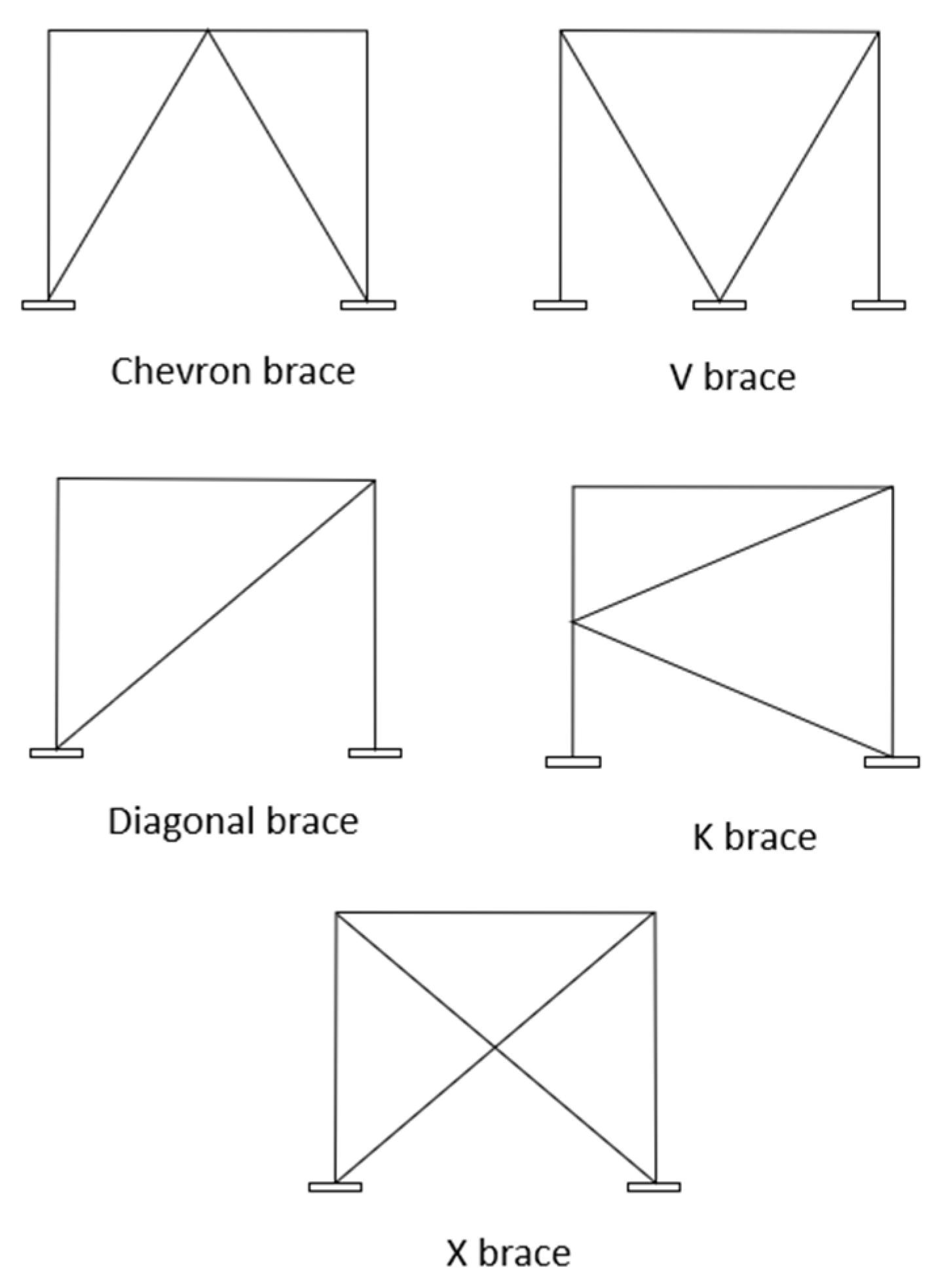
Braced frames are also called shear trusses, synonymous with vertical trusses. Their prime function is to resist lateral loads through the members’ axial stiffness. Meanwhile, columns resist the overturning moment, resulting from tension in the windward columns and compression in the leeward column [9]. The elongation and shortening of columns cause lateral deformation. In a concentric braced frame (CVF), the concentric X, K, V, or Chevron (i.e., inverted V) diagonal braces form members’ network to resist horizontal shear in axial compression or tension, based on the inclination direction (Figure 2).
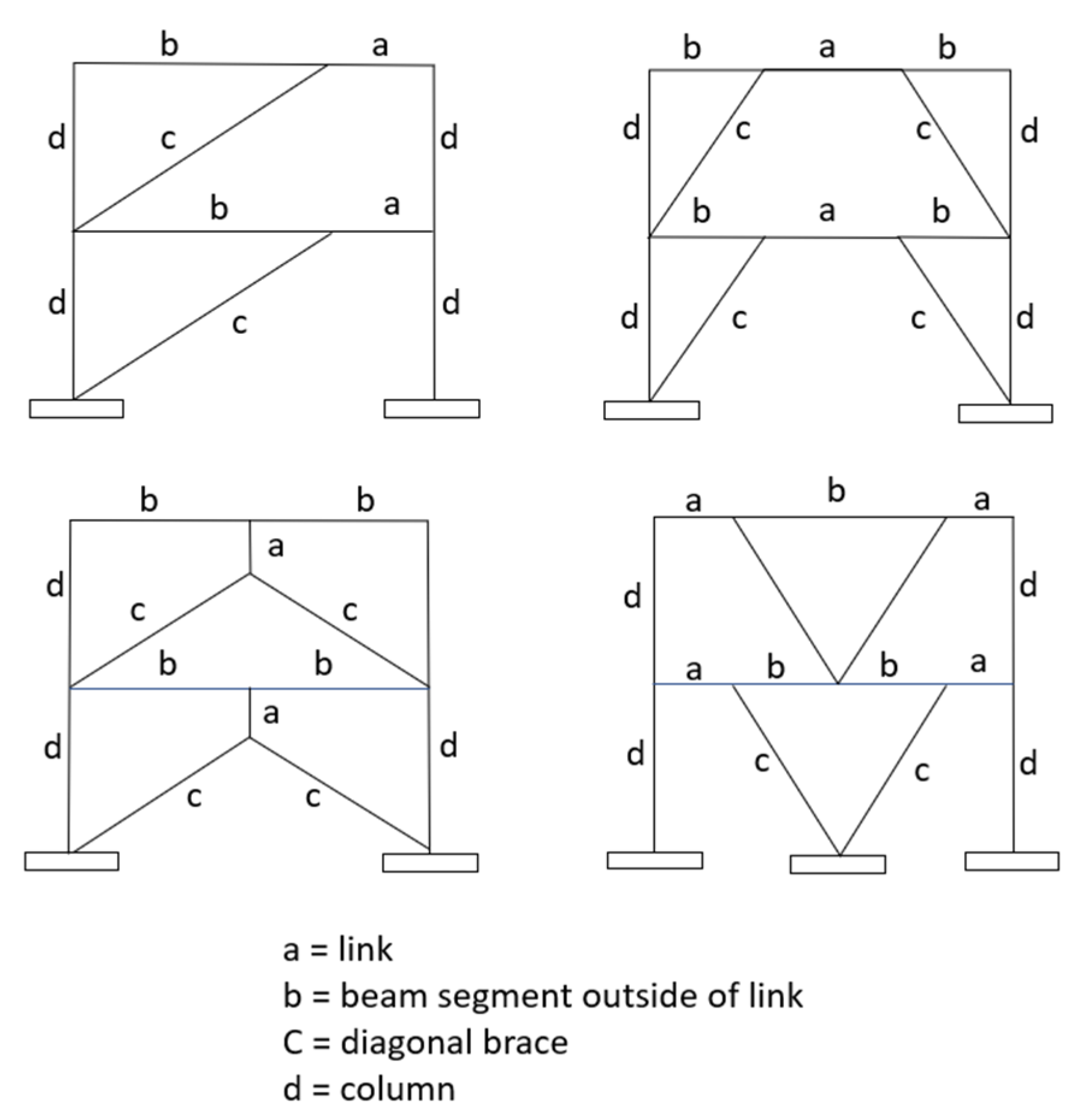
Braces are often designed to handle lateral loads, compression, and tension, although, with greater emphasis on handling the former to avoid buckling. Meanwhile, the Eccentric Braced Frame (EBF) connects braces with the floor girders to empower the frame with flexure and shear (Figure 3). This introduces ductility of the structure and, therefore, the EBF is used for structures in seismic zones. EBF is also used to accommodate wide doors and other openings in the wall [11].
3.2. Moment-Resisting Frames
Also called rigid frames, MRFs consist of rigidly connected girders and columns forming a planar grid structure. Such frames resist loads primarily through the flexural stiffness of the members. The MRF’s lateral deformation is mainly due to the frame’s shear racking and partly due to column elongation and shortening. MRFs are the most common structural systems in both steel and concrete high-rises and were the primary system in the past before the advent of more advanced systems. They provide flexibility in the architectural planning of tall buildings and are structurally efficient for 20 to 30 stories. MRFs for steel structures can be formed either by welded or bolted joints. For reinforced concrete frames, the joints are monolithically constructed in which the reinforcing steel detailing accommodates stress reversals caused by wind or earthquake forces acting in alternate directions.
3.3. Shear Wall Systems
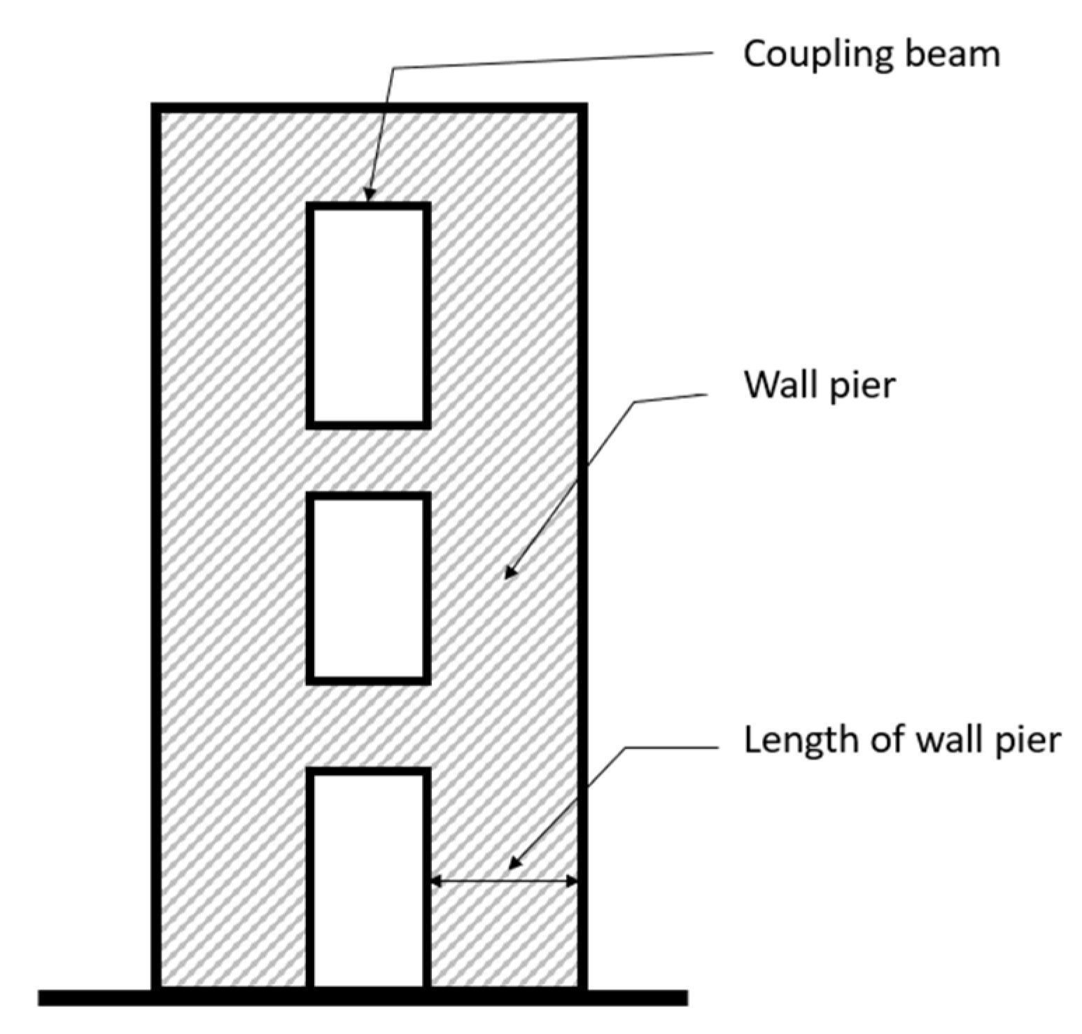
Reinforced concrete planar solid and coupled shear walls have been popular systems used for high-rise buildings in the past to resist lateral wind and earthquake loads. For coupled shear walls, two or more shear walls in the same plane are connected by a connecting or link beam or slab typically over door openings, and they work as a single integral unit (Figure 4), i.e., their total lateral stiffness exceeds the sum of the stiffnesses of the individual shear walls. Independent shear walls in combination with core walls making up the shear wall and core systems have also been popular. Isolated shear walls and cores made up of shear walls are treated as vertical cantilevers fixed at the base. For tall buildings, shear walls carry not only the lateral shear but also gravity loads imposed on them, and also they act as flexural members. Shear walls in tall office buildings are generally located around service and elevator cores and stairwells. In residential tall buildings shear walls are typically placed between apartments, and in some cases around a smaller number of elevators and stairwells.
Shear walls increase the building’s natural frequency and reduce wind-induced acceleration to ensure occupant comfort. This, however, leads to greater seismic forces on the structure, and hence in several cases, shear walls may be undesirable unless they are made sufficiently ductile. However, after a few recent earthquakes, it has been observed that shear walls keep the buildings stable against total collapse and may be beneficial for residential buildings to ensure increased safety of occupants [12,13,14].
It is noted that the steel braced frames discussed above behave like concrete shear walls. The choice of a particular system for a high-rise building depends upon the structural designer who makes the decision based on practical considerations in collaboration with the architect.
3.4. Shear Wall-Frame and Shear Truss-Frame Interaction Systems
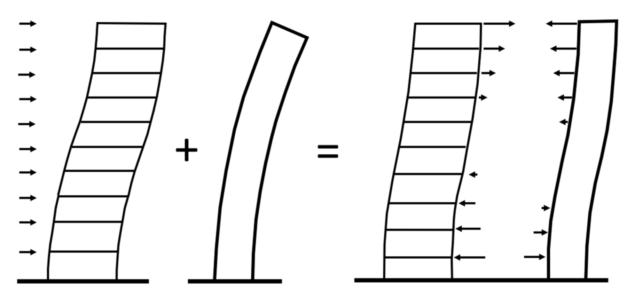
It was first recognized by Fazlur Khan that when shear walls and MRFs are used together in a tall building with standard rigid floor diaphragms connecting them, the two structural systems do not necessarily act independently, but respond to the lateral loads as combined systems, i.e., as shear wall-frame interaction systems [15]. The distribution of lateral loads to the shear walls and MRFs in multistory or tall buildings is complex and depends upon the relative stiffness characteristics of each shear wall and each MRF along the entire height of the building. Figure 5 shows the distribution of the internal forces and the deflection profile of the combined system if the two independent elements act interactively. The interactive system results in a typical deflected shape of the structure as the two elements are forced by the rigid floor diaphragm to deflect in the same way. This paved the way for the development of latter-day interactive combined systems for tall buildings. When shear trusses are employed with MRFs, the combined system performs a similar interactive behavior.
3.5. Core-Outrigger Systems
The core-outrigger system is an excellent efficient system for tall buildings. The horizontal outriggers in the form of trusses in steel structures and walls in concrete structures are connected between the structural core and the perimeter structure. They act as stiff headers inducing a tension-compression couple at the core and the outer structural system. Belt trusses are often provided to evenly distribute the tensile and compressive forces to the exterior frame columns (Figure 6). They also help in minimizing the differential elongation and shortening of the columns. The outriggers activate the participation of columns in compression and tension. The core is engaged in resisting the horizontal shears, and the outriggers are used in transferring the vertical shear from the core to the exterior columns. The outriggers provide rotational restraint counteracting rotations to the highly stiff core by creating a reversal of curvature of the core, resulting in the reduction of the overall lateral deflection of the building [16].
The core-outrigger systems may be formed in steel, concrete, and composite systems. These systems allow the perimeter columns to be widely spaced, thereby opening the building’s exterior by reducing the obstruction created by the closely spaced columns or braces, thus enabling the architects to articulate the façade design freely. Many of the functional benefits and the fact that they are adaptable to different heights and structural and architectural planning scenarios have made these systems popular [17].
3.6. Tubular Systems
A tubular building is a three-dimensional structural system utilizing the perimeter framing system comprising closely spaced columns to resist lateral loads. The earlier application of a tubular structure is by Fazlur Khan, who initially thought of it in 1961 and developed the mechanics and mathematical model of the tube form. He designed the 43-story DeWitt-Chestnut Apartment Building in Chicago, a tubular building completed in 1965. He created the rationale for the tube concept [5], pp. 8–10. The introduction of tube systems for tall buildings was revolutionary since, for the first time, the three-dimensional response of structures was explicitly recognized, departing from the conventional planar rigid-frame system. This system required fewer interior columns to carry gravity loads alone that allowed large open spaces with long interior spans, a core, a clearly visible column grid, leading to glass-box architecture. The advent of high-speed digital computers during the period also made it possible to analyze tube structures of enormous height and behavioral complexity. Khan developed the earliest structural forms of tubular system and applied them to actual buildings beginning with the basic tubular form called the framed tube, as well as braced tube, bundled tube, and tube-in-tube.
3.6.1. Framed Tube
This system is based on an analogy to a solid wall tube in which “punched holes” are created for window openings by piercing through the walls. In this system, the building has closely spaced columns and deep spandrel beams rigidly connected to each other throughout the exterior frames. The objective is to design a structure that approaches the behavior of a vertical cantilever within practical limits. The monolithic nature of reinforced concrete is ideally suited for this system, although it can be also used for steel buildings. Exterior column spacing should be between 1.5 m and 4.5 m. Spandrel beam depth should be from 0.6 m to 1.2 m. The structural organization offers a structural expression of the façade and thus defines the architectural fenestration and cuts cost by eliminating the need for mullions in addition to the saving of materials due to the inherent structural efficacy of the tubular form.
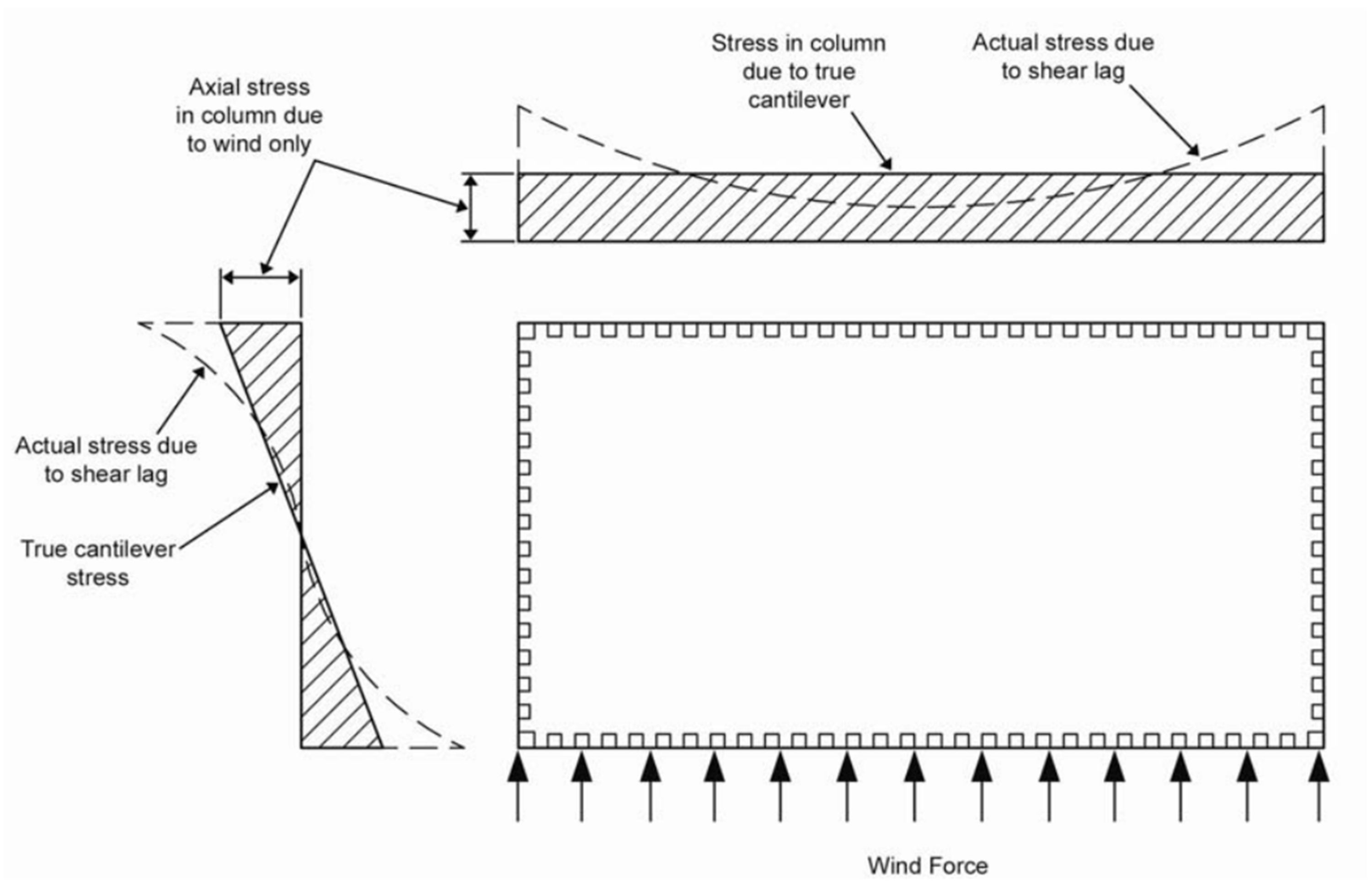
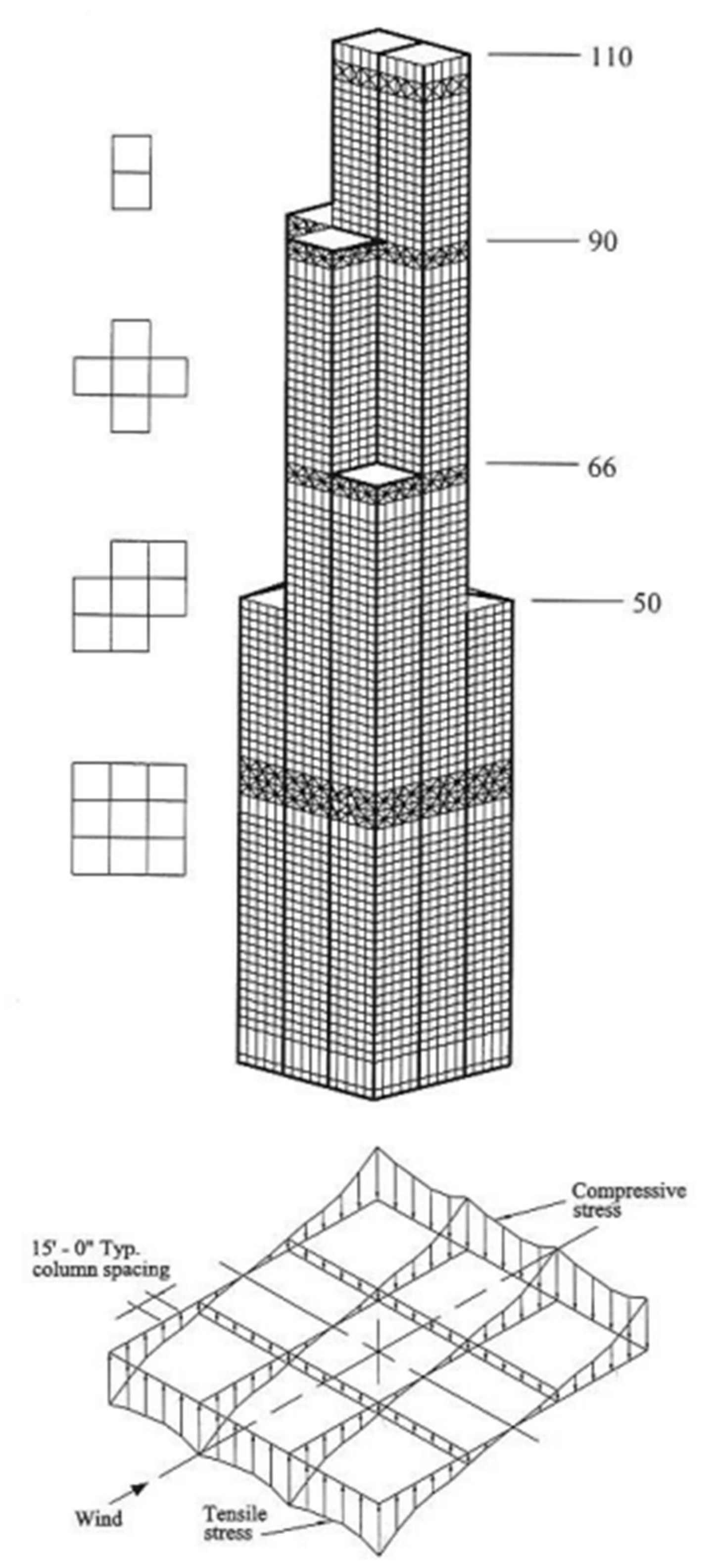
The purpose of efficient design of a framed tube is to minimize the shear lag effect in the structure. The axial forces in the corner columns are the greatest in a framed tube subjected to lateral forces. As shown in Figure 7, the distribution of axial forces is nonlinear in both the web frame (i.e., frame parallel to wind direction) and flange frame (i.e., frame perpendicular to wind direction). For a solid wall tube the corresponding distribution is linear along the web frame and linear and uniform along the flange frame. The nonlinear distribution takes place as the walls are pierced with window openings due to “shear lag”.
Post-1980s, the framed tubes became less prevalent because they interfered with the façade design. However, they reappear in recent examples, such as the 426-m tall 432 Park Avenue in NYC and the 445-m tall Marina 106 in Dubai, UAE. Notably, these towers are residential buildings where the façade design could be adjusted to fit the framed tube systems.
3.6.2. Braced Tube
Tall structures with diagonalized bracing are not new. Tall structures, such as the Eiffel Tower or the steel transmission towers, are examples of this. Myron Goldsmith had considered a steel high-rise with a diagonally based exterior as early as 1953 for his master’s thesis at the Illinois Institute of Technology [8]. John Skilling’s Pittsburgh Building of 1957, which was submitted for his successful nomination as an honorary member of the American Institute of Architects, also had diagonal bracing in the building’s perimeter [18]. However, it was not known in the 1950s that such a system could act as a tubular structure.
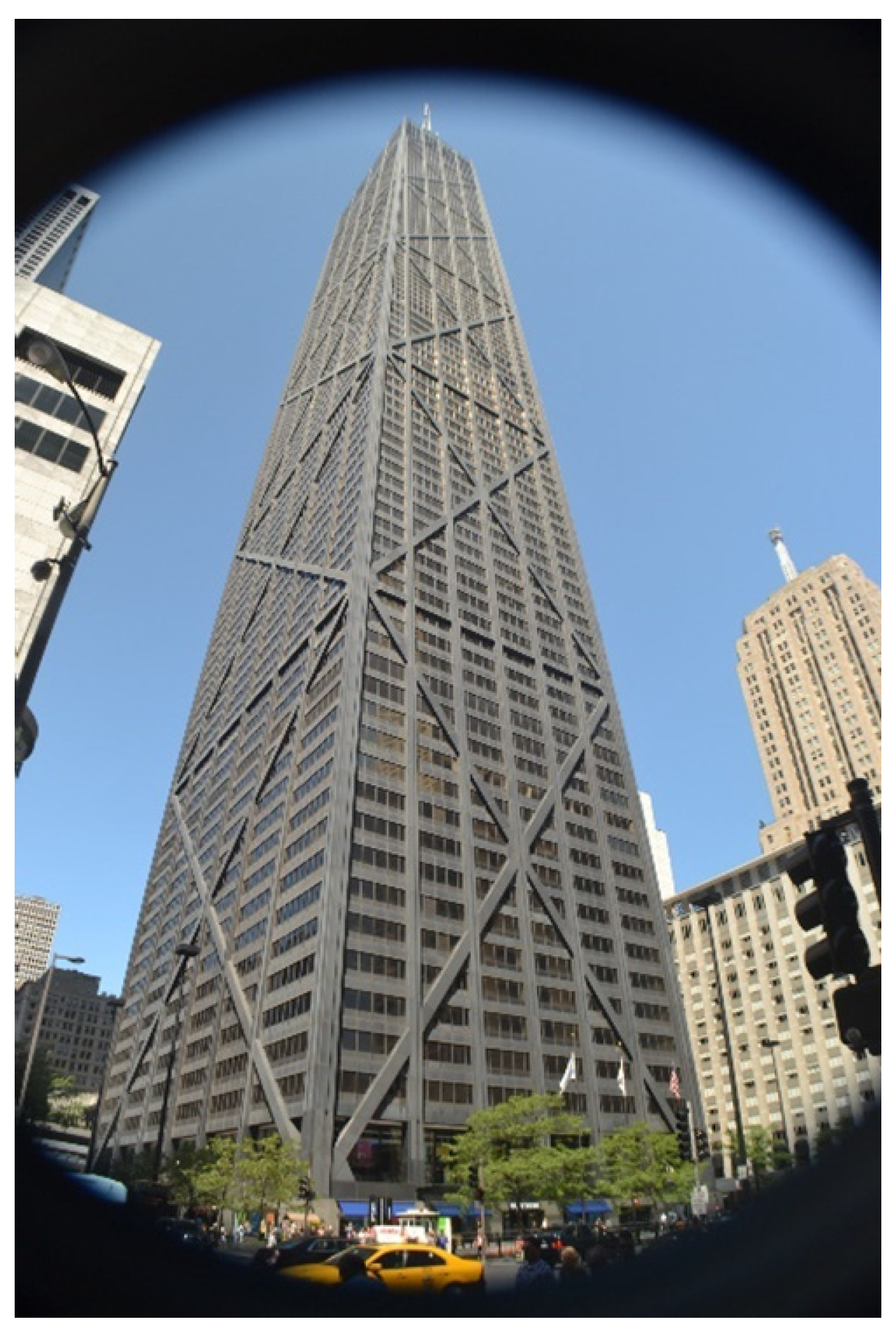
The braced tube concept was first applied to the 100-story John Hancock Center (1970) in Chicago (Figure 8). In such a tube, instead of using closely spaced columns in the perimeter, widely spaced columns are stiffened with diagonal braces to create wall-like characteristics. The framed tube becomes inefficient over about 60 stories as the cantilever behavior of the structure is undermined, and the shear lag effects are aggravated. A braced tube immensely stiffens the exterior framing in its own plane, allowing the frame to behave like a wall which enables the building to be taller. The braces also collect gravity loads from floors and act as inclined columns. The concept of the braced tube was also applied to concrete structures. The 58-story Onterie Center of 1985 in Chicago is an example of this.
3.6.3. Bundled Tube
When two or more individual tubes are joined together creating a bundled tube they act synergistically as a single unit and allow a tall building to ascend higher than a single tube. For very tall building a single tube loses its structural efficiency as the width of the building at the base becomes enormous to maintain a reasonable height-to-width aspect ratio such that the building is not excessively flexible and does not sway too much. For such a building the tubular response of its structure can be improved for strength and stiffness by providing cross walls or cross frames in the building, i.e., creating a bundled tube as a logical structural system. A bundled tube system is suitable for buildings with large footprints and is essentially a multi-duct tube shaft with direct wall-to-wall intersections. The first application of this concept was the 109-story Sears Tower (renamed Willis Tower) of 1974 in Chicago. In this building, nine framed tubes are bundled at the base, some of which are terminated at various levels with two continuing from the 90th floor to the roof (Figure 9).
Such organizational flexibility offered floor areas from very large to much smaller at the top; it gave this system an added advantage. Moreover, its massing flexibility created a novel architectural vocabulary.
A concrete bundled tube was used for One Magnificent Mile of 1983 in Chicago. In this building, individual tubes of any configuration were terminated at different heights. It is possible to bundle tubes with diagonals or bundle a framed tube with a diagonalized tube. In addition, to behave as bundled tubes, the individual tubes could be of various shapes, such as rectangular, pentagonal or hexagonal.
3.6.4. Tube-in-Tube
A tubular structure can be further stiffened by employing a stiff tubular core (solid, framed, or braced), which can carry part of the lateral load. The core acts as the inner tube, and the exterior closely spaced columns act as the outer tube. Such a system is called a tube-in-tube, examples of which are the 52-story One Shell Plaza of 1971 in Houston, Texas, and the 70-story Olympia Center of 1986 in Chicago. Both are reinforced concrete structures. Because of the confluence of the recent resurgence of framed tube and the growth of tall residential buildings with cores, both of which are typically constructed in concrete, the technology of which has advanced substantially as a modern material, the tube-in-tube system has found recent applications for cases where these are well integrated with residential plan layouts.
3.7. Advanced Tubular Systems
Earlier tall buildings featured simple geometric shapes. They were a result of extruding floor plans of squares and rectangles. Simple geometric forms fit the tubular structural systems. Examples include the John Hancock Center and Sears Tower in Chicago and the World Trade Center in NYC. All were built prior to the 1980s. Later, architects and engineers searched for new forms, featuring non-rectilinear and curvilinear shapes, step-backs, and complex tops. In conjunction with the demand for underground parking, tall and open entry lobbies, and the desire for fewer columns at the perimeter, these elements gave birth to the core-outrigger system. Simultaneously, the tubular systems have witnessed significant developments to meet these new design criteria and needs. Collectively, these new systems have enabled the building of ever taller buildings.
3.7.1. Superframes
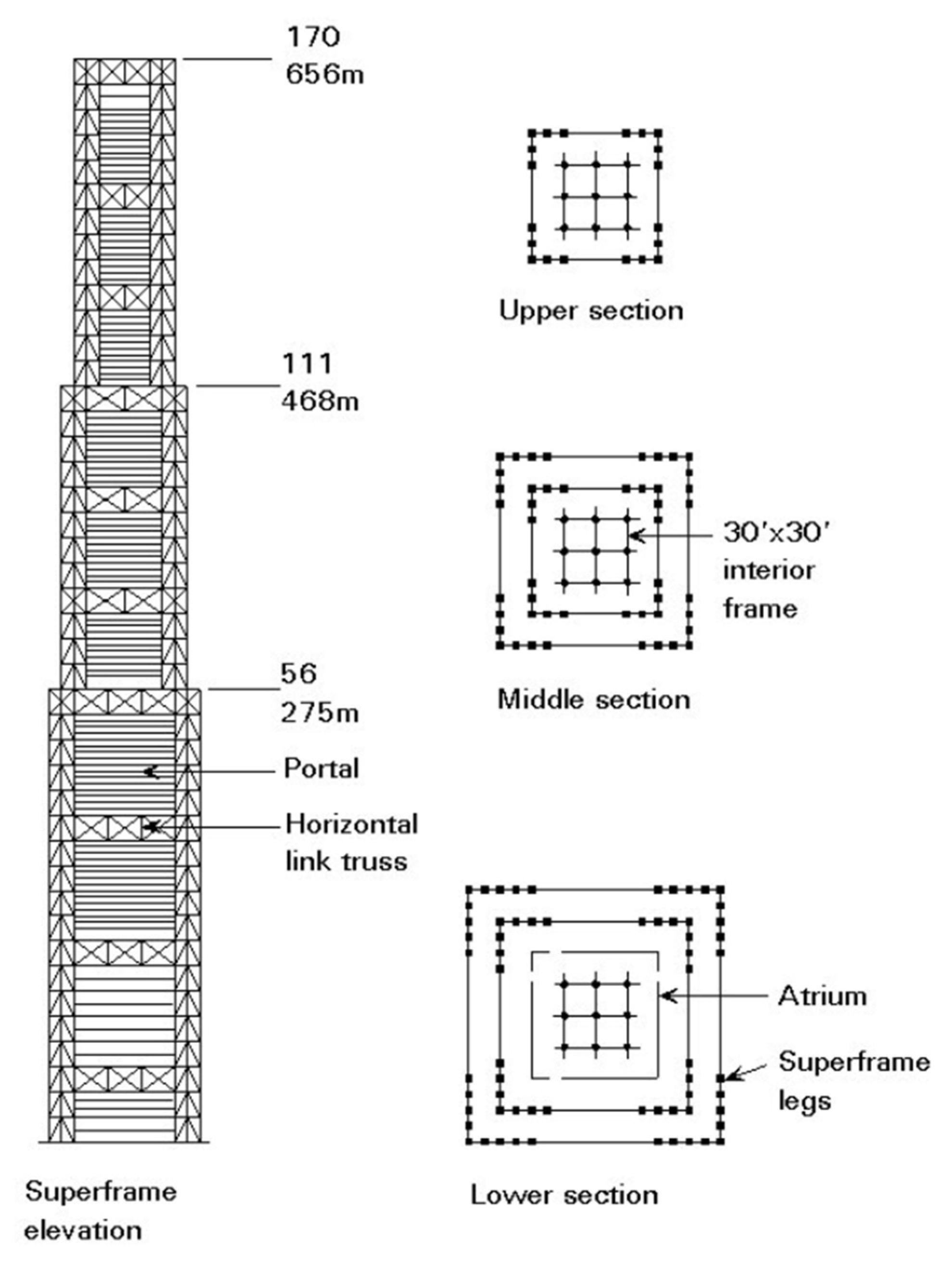
The superframe for tall buildings has many possibilities. Since the perimeter framing provides its lateral load-resisting capability, it is an extended tubular system. Myron Goldsmith conceived the initial idea of a superframe in his 1953 master’s thesis at IIT, Chicago, in which he worked on a concrete office building [8]. His superframe had eight columns forming three bays supporting seven macro floors or platforms spaced 15 stories apart. From each macro floor, seven stories were hung below, and seven were supported above, leaving the floor midway between the macro floors column-free. In 1973, structural engineers Paparoni and Holoma designed the Parque Central Towers, comprising two 56-story towers in Caracas, Venezuela. Fazlur Khan advanced the concept differently in 1981 by creating a series of vertically stacked telescope-like superframes, containing four corner megacolumns (Figure 10). He applied this concept to an unbuilt 168-story Chicago World Trade Center building [5], pp. 76–78. In this building, he used four corner megacolumns that were designed as trussed tubes. The superframe has excellent potential for supertall and megatall buildings. The feasible height can be substantially increased to dizzying heights with the use of superframed conjoined towers in which a few superframes are connected horizontally by tubular bridge structures [15,18].
3.7.2. Diagrids
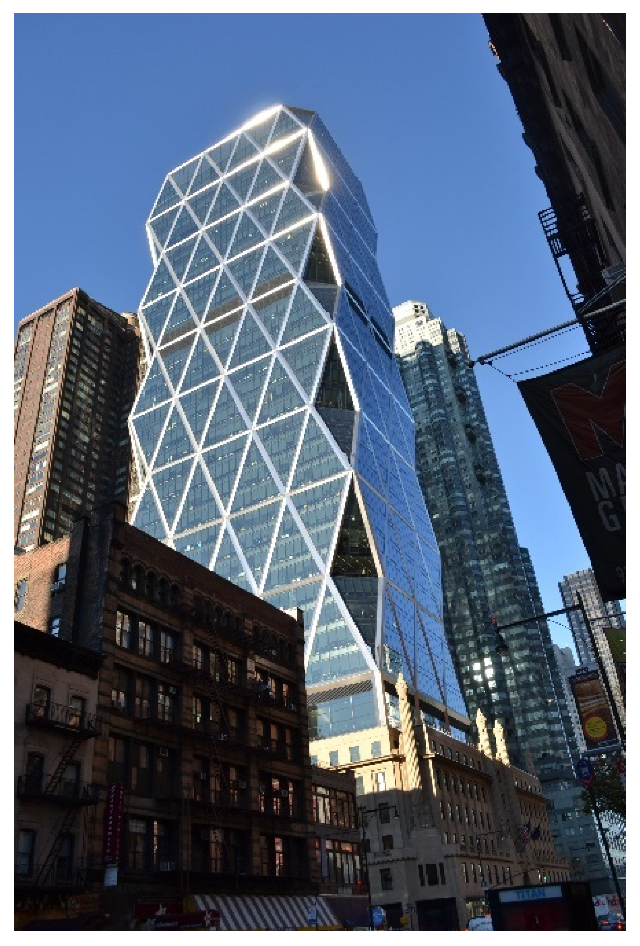
The diagrid structure is a modified braced tube system and has recently gained popularity. In a braced tube, which is a very stiff system, perimeter columns are present and large braces are also used. In diagrids, however, many lighter diagonal elements on the exterior crisscross at nodes in which the columns are eliminated, creating a lattice-like appearance. The exterior system effectively behaves like a shell creating immense in-plane stiffness rendering the tall building to approach the behavior as a solid tube (Ali and Moon, 2007, pp. 205–223). The Hearst Building of 2003 in New York City (Figure 11) and 30 St. Mary Axe (Gherkin) of 2004 in London are the earliest tall buildings that used the diagrid system [19,20].
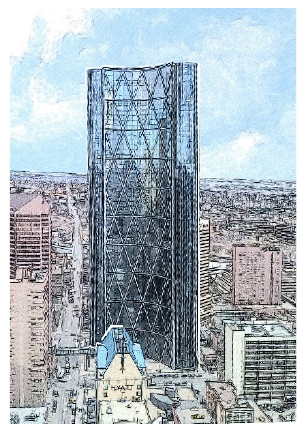
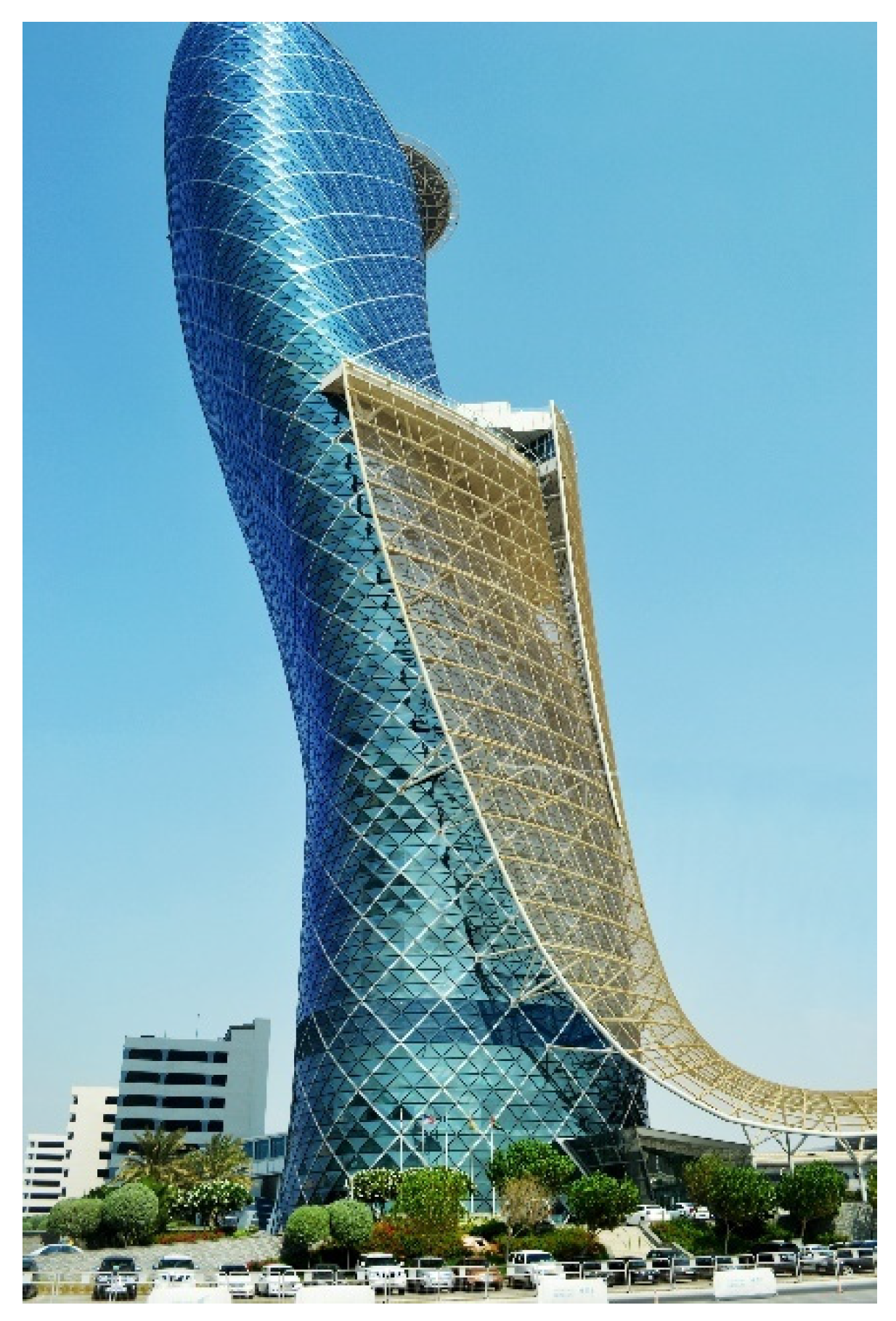
Besides structural capabilities, diagrid systems offer new aesthetic expressions. These can be analyzed by examining several elements, including scale, inclination, material, form, structural details, façade design, color, and lighting systems. Indeed, diagrid structures have the flexibility to be configured in varied ways; for example, the diagonals can be placed at uniform or variable angles and are suited to complex building shapes [21,22]. The unit size of the diagrid generates different expressions. Larger units convey bolder expressions; see, for example, the Bow Tower in Calgary, Canada (Figure 12). As such, large-scale diagrid systems are likely to suit taller buildings. Interestingly, the smaller unit diagrid allows for generating sculptural forms. For instance, the 35-story Capital Gate Building uses smaller diagrid units to achieve a twisting form that leans 18 degrees (more than the Leaning Tower of Pisa in Italy) (Figure 13).
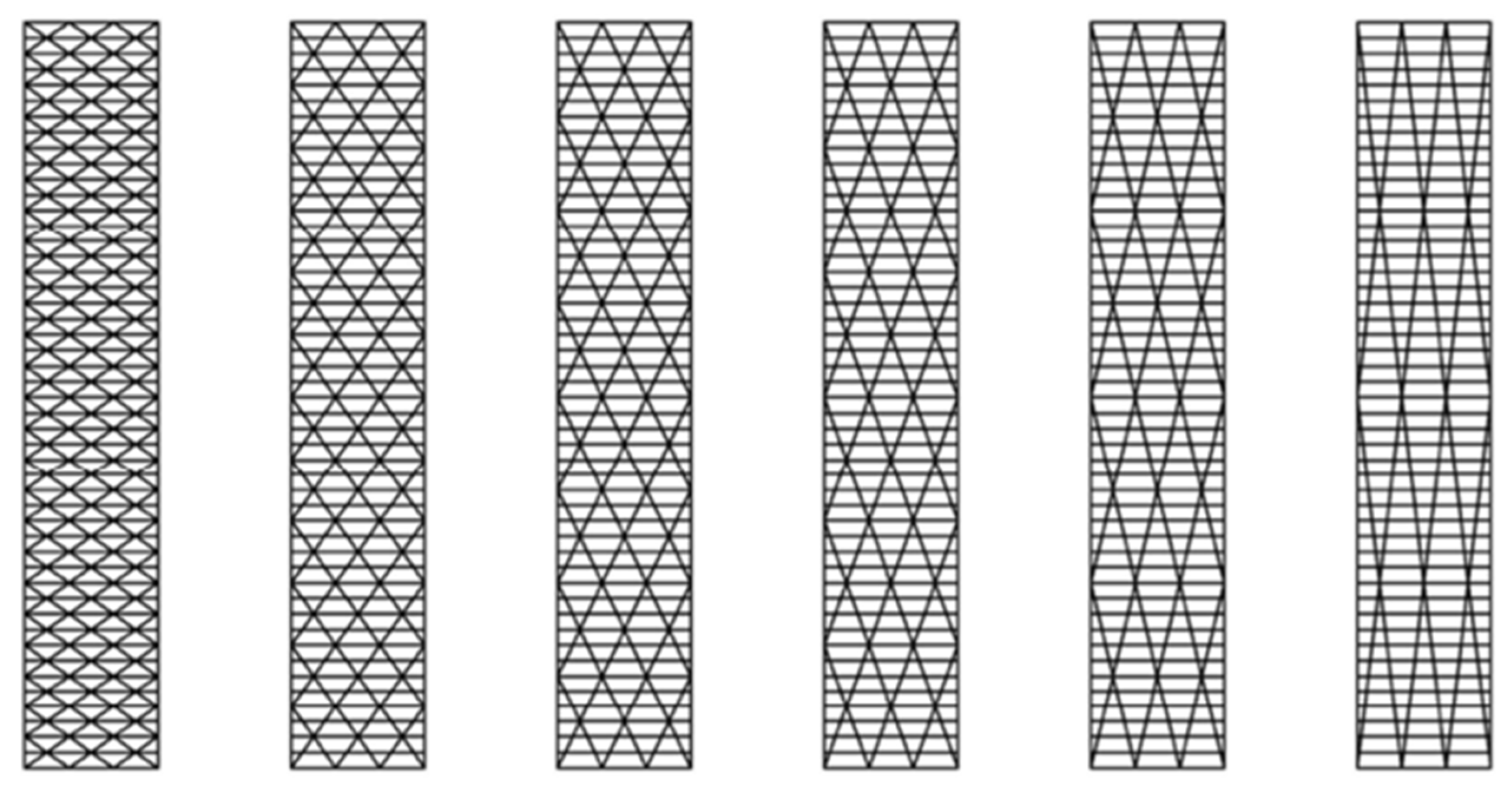
Different diagonal inclinations generate varying expressions. Overall, shallower angles generate denser diagrids that convey heavier systems and vice versa; steeper slopes yield spread-out diagrids that give lighter systems (Figure 14). Different materials for the diagrid system lead to different visual expressions. For example, steel diagrids are likely to communicate high-tech expressions. Steel is expected to suit taller buildings [20]. In some cases, progressively denser diagrids can be employed towards the base of the tall buildings where the loads imposed by the lateral wind forces are the greatest.
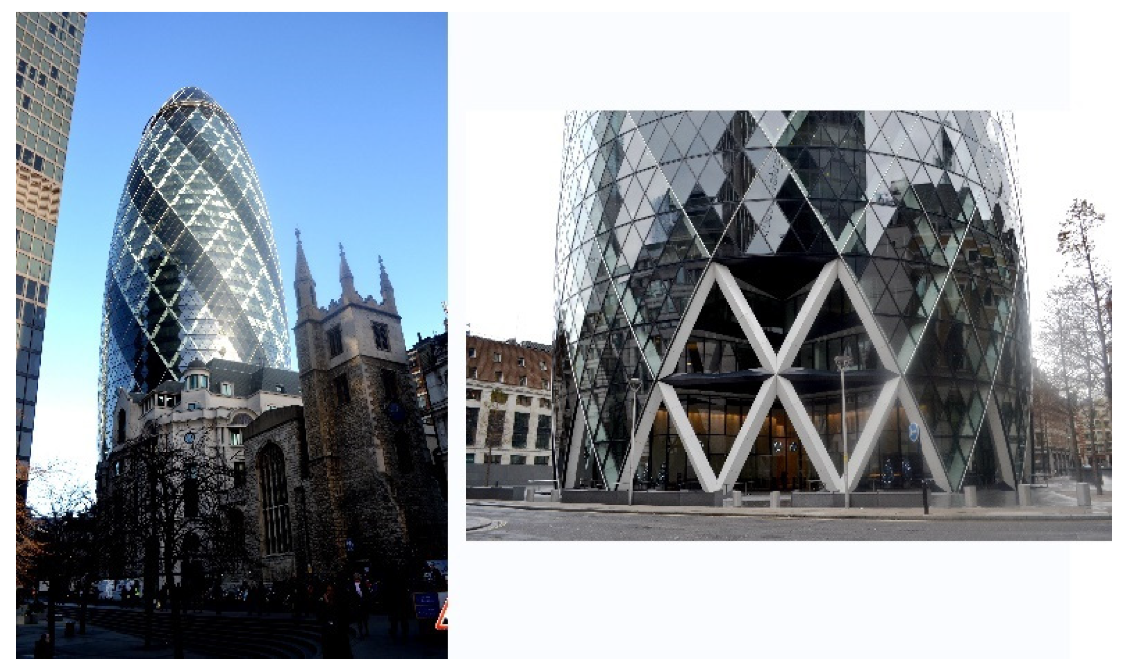
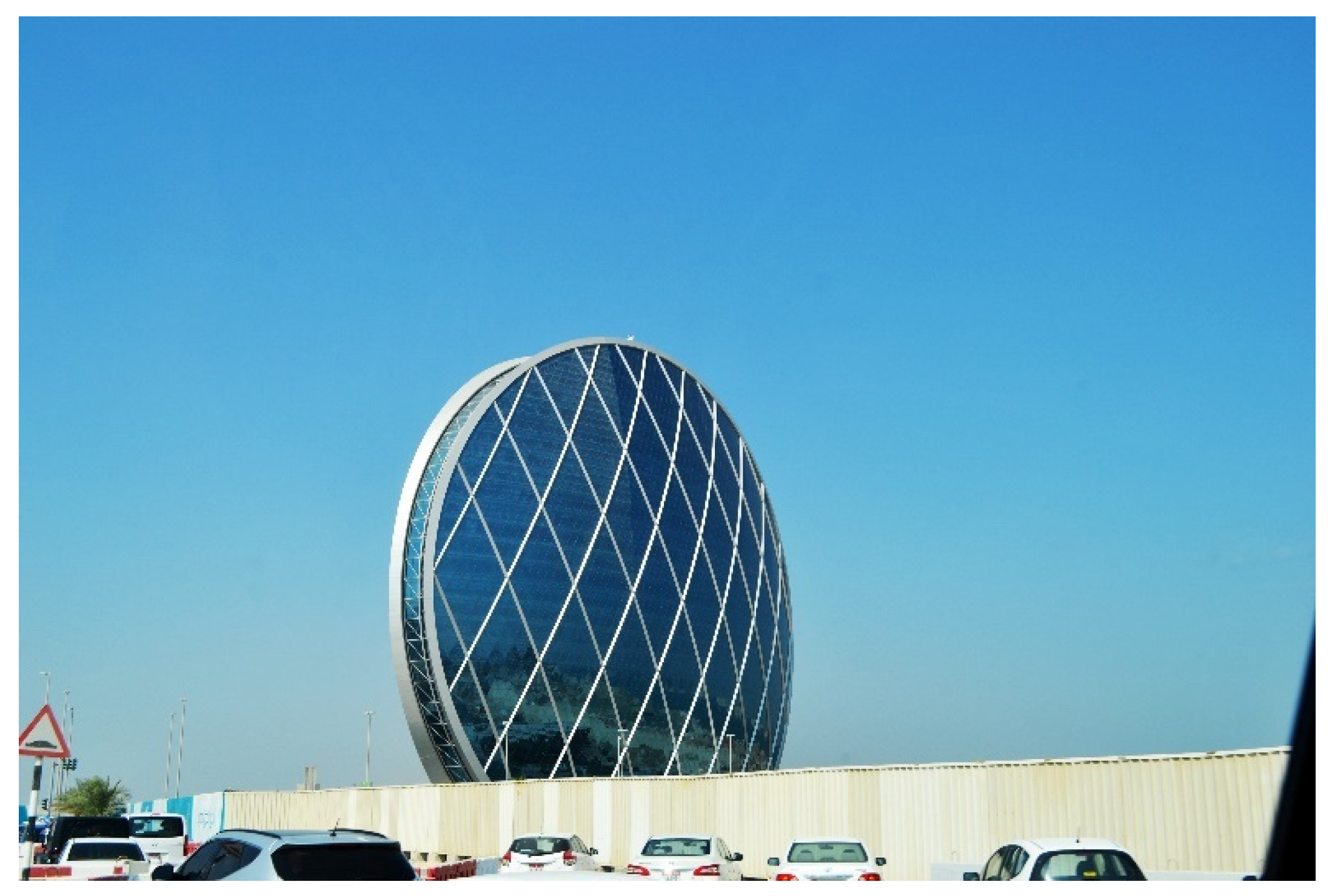
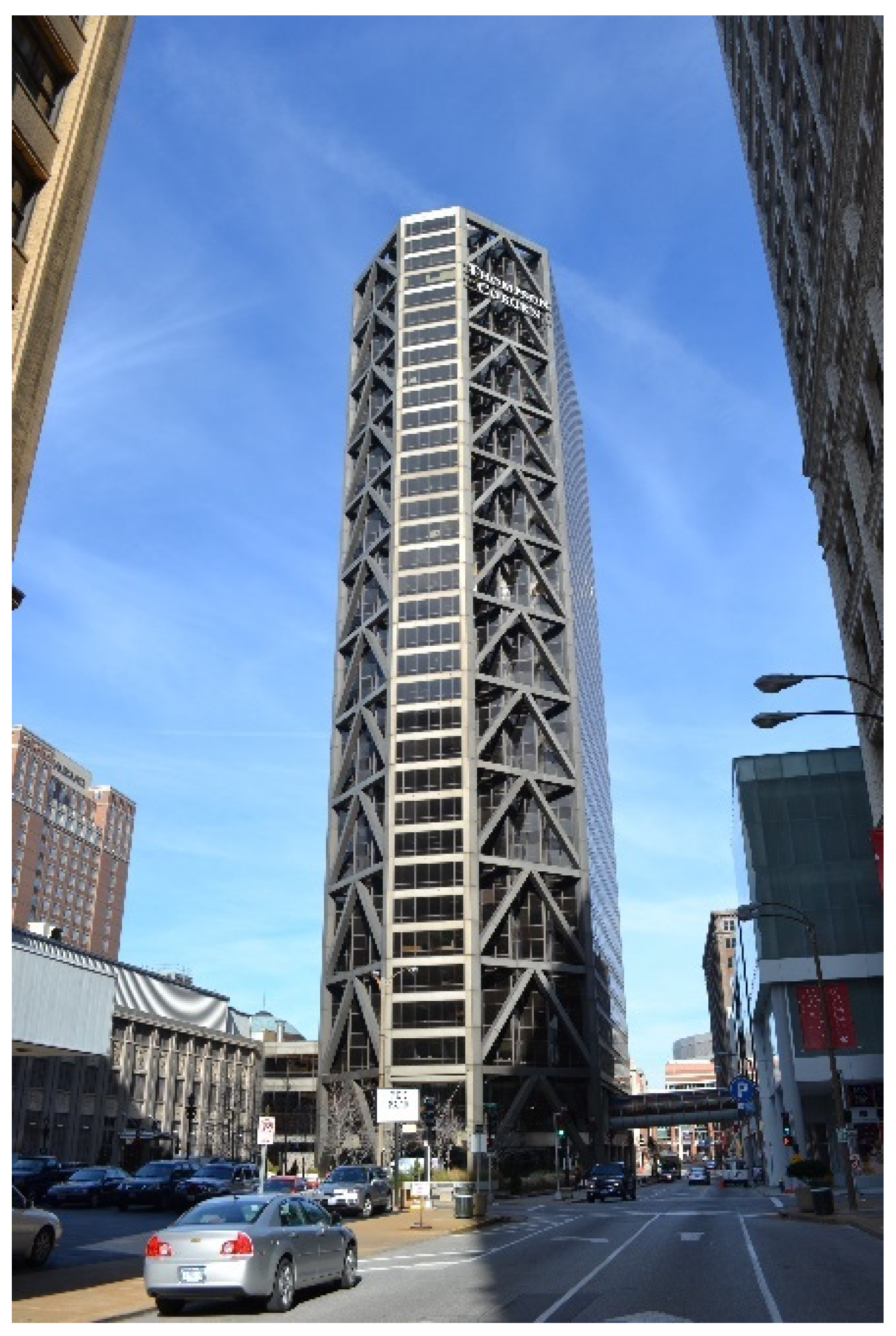
Applying diagrids to different building forms leads to various aesthetic expressions. For example, the diagrid system in the Gherkin (30 St Mary Axe) Building in London, UK, generates a dynamic form (Figure 15). Similarly, the diagrid employed in Al Dar Headquarters in Abu Dhabi, UAE, generates exciting and novel aesthetics (Figure 16). Further, using different colors leads to a variety of visual expressions. For example, the diagrid system of Calgary’s Bow uses a lighter color that contrasts nicely with the darker curtain wall. The NEO Bankside Complex employs warmer colors that convey an inviting residential function. Interestingly, dimmer-color structural systems used in the past century reflected industrial expressions [20]. Examples include One Maritime Plaza (1964) in San Francisco, California, the John Hancock Center (1970) in Chicago, Illinois, and One US Bank Plaza (1976) in Saint Louis, Missouri.
3.7.3. Braced Megatube
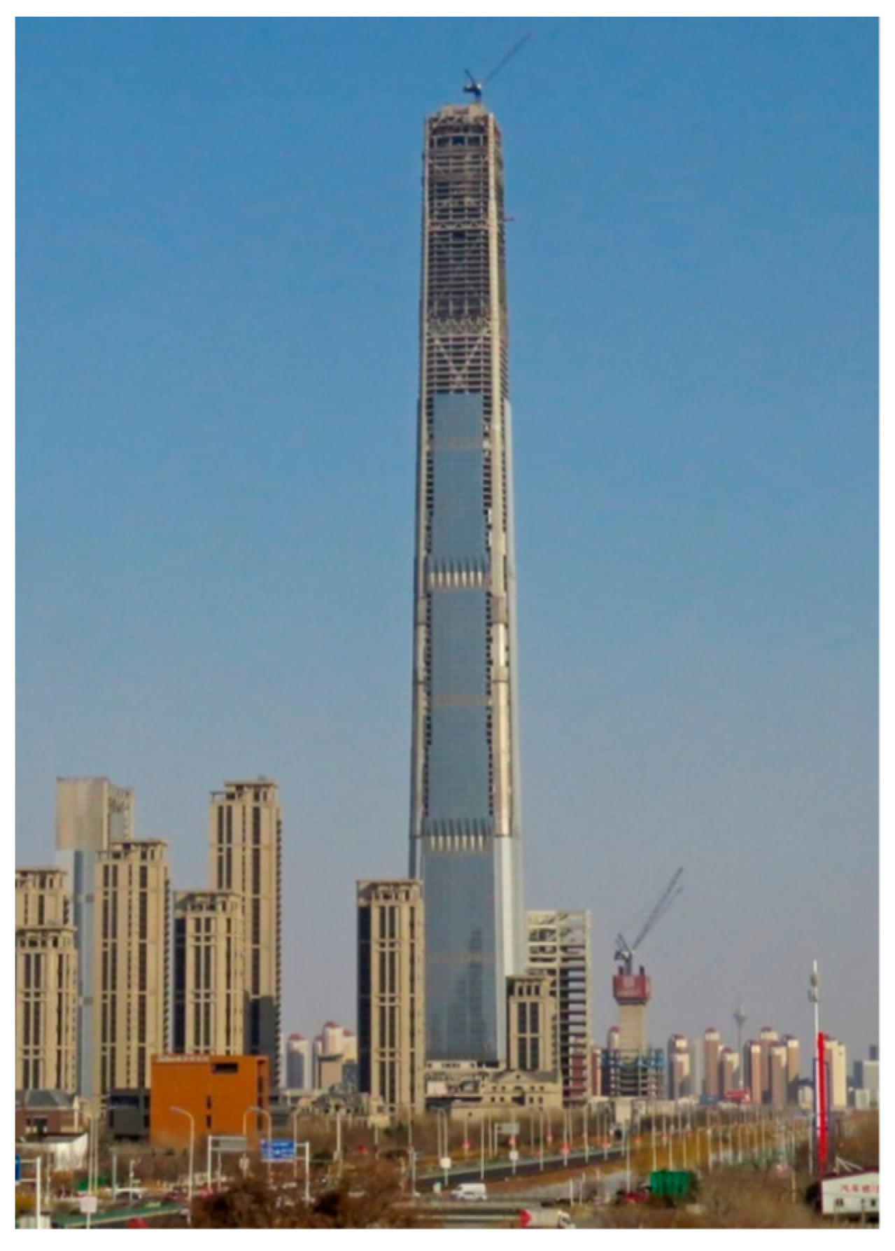
Among the basic tubular systems described in Section 3.6, the braced tube system with large diagonals is the most efficient one. Taking the braced tube as a basis, Fazlur Khan envisioned that much improved structural efficiency could be achieved in an “ultimate structure,” in which large megacolumns are in the four corners of the building with massive X-braces between two corner megacolumns on the same side of the building are provided [14,15], p. 423. This structural concept has been implemented in supertall buildings. For example, the 597-m tall Goldin Finance 117 building in Tianjin achieves structural efficiency by integrating four corner megacolumns with large belt trusses (placed every 15 stories) while mega X-braces connect the entire structure at the exterior (Figure 17). Such a structure offers stability against lateral forces. It also transfers gravity loads from the belt trusses to the megacolumns efficiently [19].
3.8. Composite Building Structure
This system was conceived for modern tall buildings by Fazlur R. Khan for the 36-story Gateway III Building (renamed 222 South Riverside Plaza) of 1972 in Chicago, employing a composite tube system. However, its construction was completed after the 20-story Control Data Center, another mixed tube building in Houston, Texas, completed in 1971. Khan also employed it in a taller 52-story One Shell Square Building of 1972 in New Orleans, Louisiana. In this system, concrete is poured around the light, closely spaced exterior steel columns of the tube, allowing their speedy erection. The interior gravity steel columns and floor framing are executed like typical steel tube buildings. The system thus allows fast construction as the steel perimeter columns already erected are strengthened and stiffened by the concrete poured around them, which introduces fireproofing and damping to the building. The interior steel columns save floor space by avoiding large concrete columns there. The system is thus a combination of structural steel and concrete that complement the qualities of each other while eliminating the drawbacks.
Composite building systems can now be of other forms than composite tubes. Concrete cores containing building services are very popular for lateral load-resistance and for allowing the building to have fewer columns, thereby creating openness of facades. It is also possible to make the core itself composite by adding steel plates to the core walls on their faces. Composite construction can be conveniently used for core-outrigger systems. Since many possibilities exist for a composite structure, it has become a popular method of construction [24], pp. 534–536.
3.9. Combined and Shared Systems
Although combined systems are not new and can be present in tall buildings in many forms, an early such system mainly occurred in the shear wall-frame interaction model. A towering structure results in excellent strength and stability when the prime components of the combined lateral load-resisting systems share loads with one another. When the core interacts with the exterior frames, the shared components perform dual functions. The tube-in-tube system is one example of a combined system. An example of a shared system is a core-outrigger system combined with a megatube in which the megacolumns are shared by both systems, i.e., by the core-outrigger and megatube systems. The 492-m tall 101-story Shanghai World Financial Center in Shanghai, completed in 2008, exemplifies the shared system [16].
3.10. Concrete Core System
Because of the rapid advancement of concrete technology, concrete as a structural material has become popular for supertall and megatall structures for residential tall buildings and for use in composite tall buildings. Besides concrete advancement, a significant trigger for using concrete, particularly for the cores, was the collapse of the World Trade Center Towers in New York City (2001), since the steel-framed core failed to withstand fire [25,26]. A core made of advanced, strong concrete could allow tenants to run down the stairway, escaping a fire. In addition to fire resistance, the concrete core offers resistance to lateral loads. Consequently, prominent recent supertall buildings have been using concrete cores. Examples include the Citic Tower in Beijing, Shanghai World Financial Center in Shanghai, Lotte World Tower in Seoul, and Goldin Finance 117 in Tianjin.
Buttressed Core
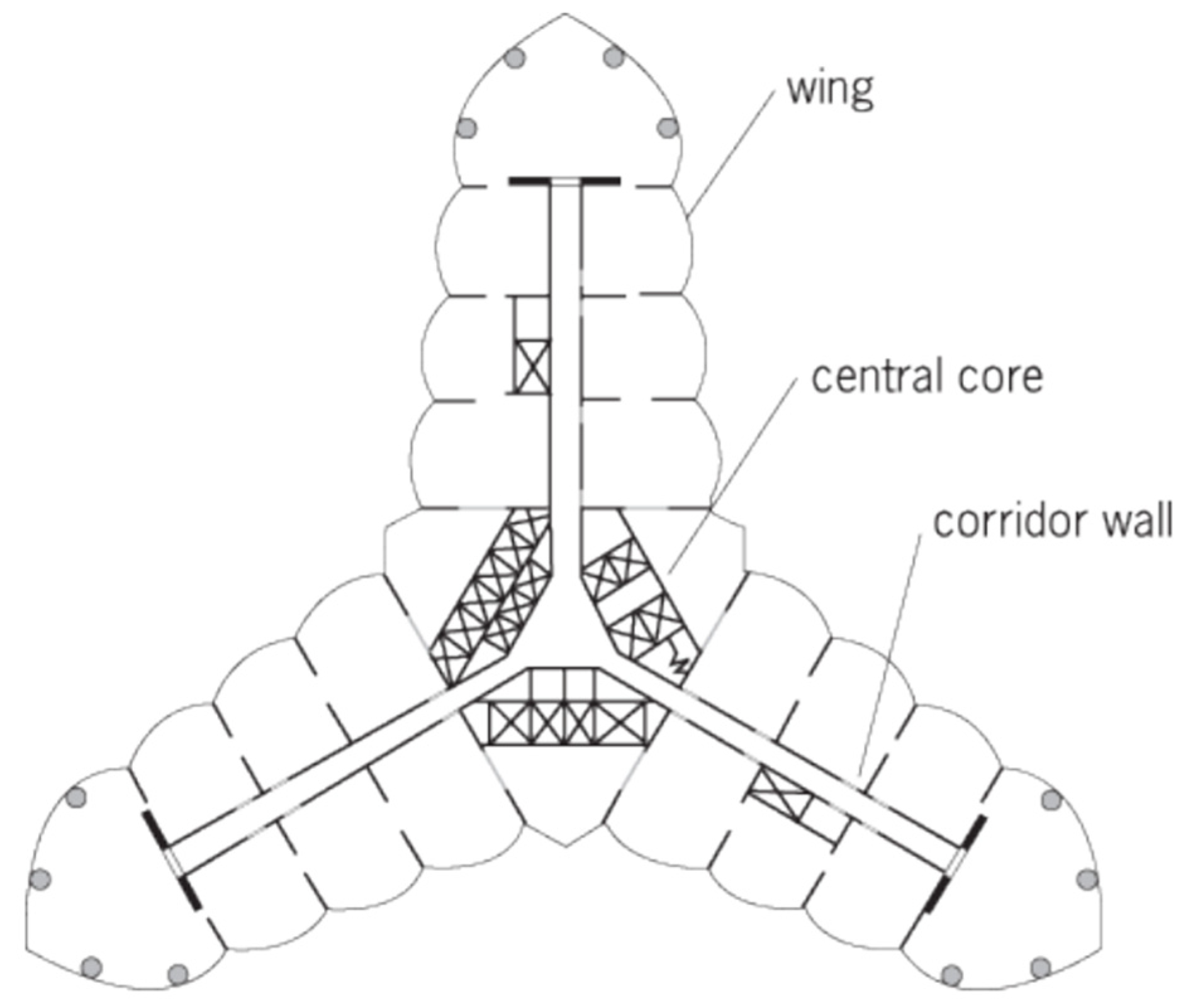
The prominence of cores in current practice is exemplified by the Y-shaped 828-m tall Burj Khalifa of 2010 in Dubai, UAE, where a buttressed concrete central core acts as a tube. Because Burj Khalifa is exceptionally high, the central core was extended into corridor concrete walls of the three wings, offering structural stability to the entire tower (Figure 18). Bill Baker served as the chief structural engineer on this project.
The Y-shaped profile inherently offers structural stability. It has been used previously for tall structures, including the 553-m tall CN Tower in Toronto (1976), the 197-m tall Lake Point Tower in Chicago (1968), and the 264-m tall Tower Palace Three in Seoul (2004). Earlier, Frank Lloyd Wright proposed the same tripod concept for his visionary Mile-High ILLINOIS tower (1956). Colaco and his associates studied in 1986 a Mile-High megatall building and concluded that such a structure is technologically feasible [27]. Most recently, the 1-km Jeddah Tower in Jeddah, Saudi Arabia (on hold) embraces the same profile.
4. Classification of Structural Systems
For structural efficiency and minimum material consumption, tall buildings should require upgraded structural systems beyond the conventional rigid frame system for increasing height conditions. As the structure becomes taller than about ten stories, the lateral sway due to lateral forces begins to rise, and hence the lateral stiffness rather than the strength of the building controls the design. This resulted in the classification of the structural systems for tall buildings for the first time, illustrated by “Heights for Structural Systems” diagrams [6].
4.1. Height-Based Structural Systems
Khan proposed a hierarchy of structural systems for office buildings of ordinary proportions and forms that are fitting for certain heights [6,7]. He developed structural systems charts based on his intensive research aided by computer simulation for both steel and concrete [5], p. 55; [28], p. 117. According to Khan, other than the rigid frame, the feasible structural systems for high-rise buildings are shear walls, shear wall-frame interaction, belt trusses, and several tubular systems. This template of structural systems was intended to be a guideline and should be considered a rule of thumb. In fact, each system has a wide range of height applications depending upon other design and service criteria related to several factors, including building form, height-to-width aspect ratio, architectural function, exterior load condition, the environment, and site constraints. However, there is an optimal structural system for every factor or combination of factors, which may not necessarily match one of the proposed schemes due to the prominent influence of other factors on a building. Developing these revolutionary structural systems charts is a critical milestone in growing and expanding tall buildings’ structural systems. They acted as a powerful catalyst in the rapid development and use of them in the construction of tall buildings in the 1970s and 1980s and onward. They also paved the way for more innovative and hybrid future structures. Later, Elnimeiri [29], pp. 102, 106 proposed two modified height-based structural systems for steel and concrete structures.
4.2. System-Based Structural Systems
Khan’s height-based charts for steel and concrete have fostered the development of new structural systems for supertall buildings [6,7]. Ali and Moon examined these developments and published in 2007 their findings in the form of expanded charts with a broad classification based on height and interior and exterior locations of lateral-load resistance structural systems [16]. Subsequently, in 2018, Ali and Moon updated these charts, including newer structural developments [19]. While Khan’s charts offered separate steel and concrete structures, these updated system-based charts integrate steel, concrete, and composite structures. Based on the project-specific design requirements, the height-to-width aspect ratios of the buildings allowed for a variation of up to 10 for the charts. The indicated number of floors in the charts is approximate, and the structural engineers will determine the final heights of the buildings [19].
5. Structural Systems and Aesthetics
Tall buildings are built to fulfill human needs. Commercial tall buildings allow the concentration of office spaces in smaller urban cores, creating business synergy and fostering close interaction among masses of people. Residential tall buildings satisfy different needs of concentrating many people living in smaller areas, creating vibrant neighborhoods. Similarly, towering hotels enable hosting many visitors and holding large conventions and meetings. They are often located strategically to take advantage of transportation hubs or scenic views. Today, we also see the proliferation of mixed-use tall buildings to enhance economic success by having at least parts of the building always occupied. Of course, as explained in this study, offering structural safety is also an essential need.
However, an essential role of tall buildings is to improve the city’s aesthetics. High-rises are large “objects” and exert a profound visual impact on their surroundings. Architects and engineers see them as opportunities to express innovative aesthetics and beauty. They are often dissatisfied with the widespread unattractive cookie-cutter projects that are manifested in prevailing public housing or the widespread use of the modernists’ template, i.e., the “refrigerator box”. Consequently, they collaborate to generate buildings with unique aesthetics whenever opportunities arise.
An exciting opportunity to reinforce innovative and logical aesthetics is structural expressionism. Structural expressions allow displaying the structural rationales that enable reaching greater heights while ensuring stability. Tall buildings can express their structural systems, offering powerful expressions in which the structure defines the architectural expression. Due to their massive scales, these expressions are amplified and could exert profound visual impacts on their surrounding environments. In this case, the resulting aesthetics are not subjective or based on the whims and artistic visions of the architects. Instead, they express scientific logic and rationalism that follow laws of gravity and wind resistance principles while meeting essential human needs, increasing structural efficiencies, and reducing construction costs. The outcome is that by looking at the building, the viewer will likely visualize its overall structural system, load path, and stress flow. The building would visually illustrate how physical loads are transferred from high altitudes to the ground. In this framework, Louis Sullivan’s architectural principle that “form must follow function” could be modified as the form must follow the structural system and respect its natural forces. In other words, “form controls the forces … this means that function follows form and not the reverse” [30], p. 378. The interplay of structural laws and artistic expression has generated Structural Expressionism. Specifically, the proliferation of new structural systems and advanced technologies, combined with Modernism’s principles of structural clarity, gave birth to the Structural Expressionism movement [19].
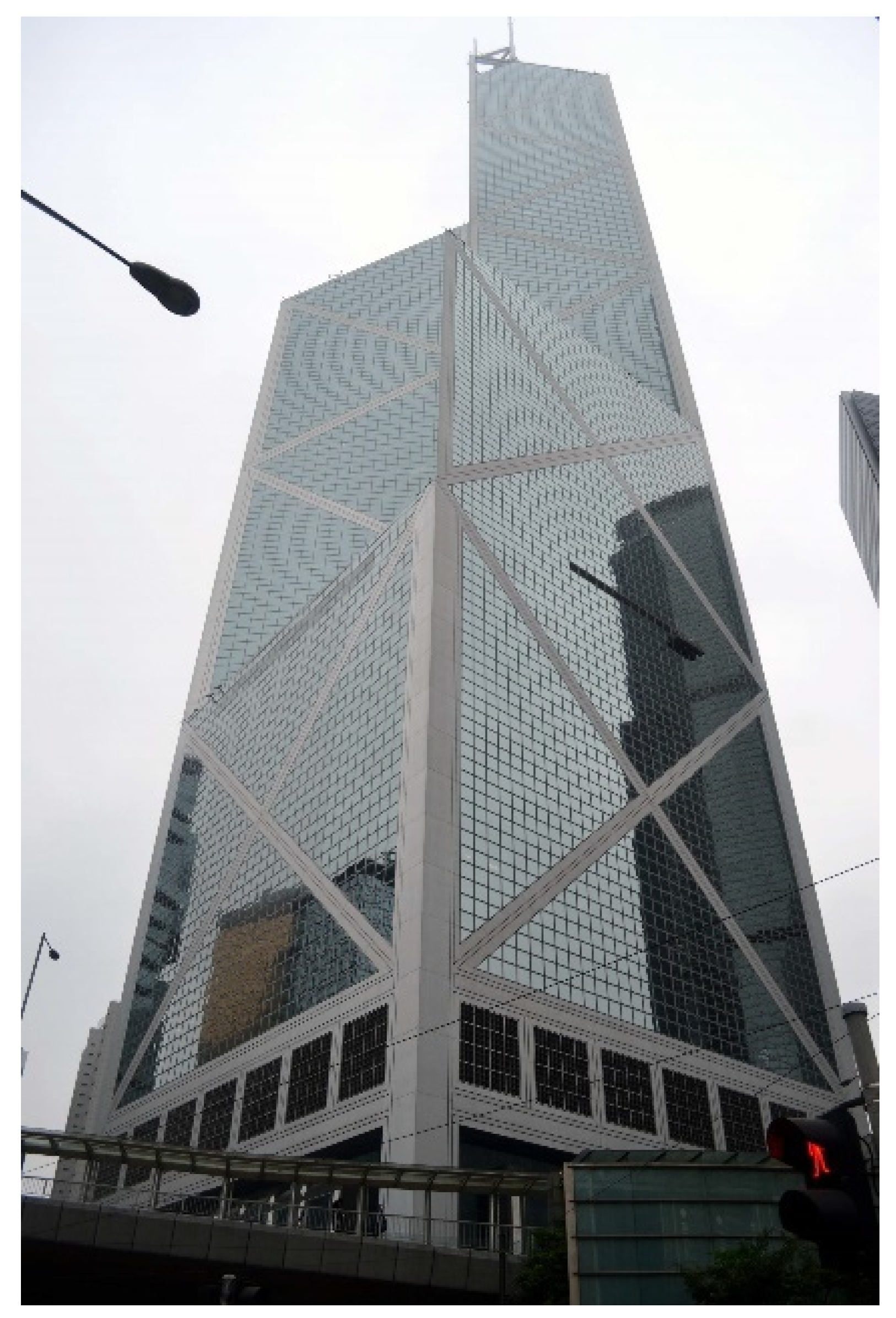
Structural Expressionism flourished in the 1960s and 1970s. It became popular partially because it was compatible with the prevailing structural principles and architectural tenets of the International Style. As mentioned earlier, a typical example is the John Hancock Building in Chicago. Other examples include One US Bank Plaza (1976) in Saint Louis, Missouri, which employs K-bracing, displayed vividly in the building’s corners (Figure 19). Interestingly, the Bank of China in Hong Kong (1990) innovatively expresses its structural system by interfacing with the changing form of the building “three-dimensionally” (Figure 20).
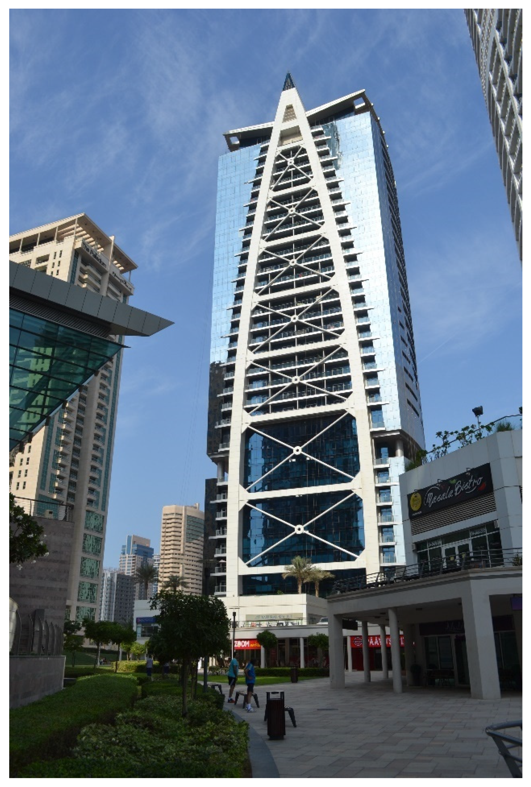
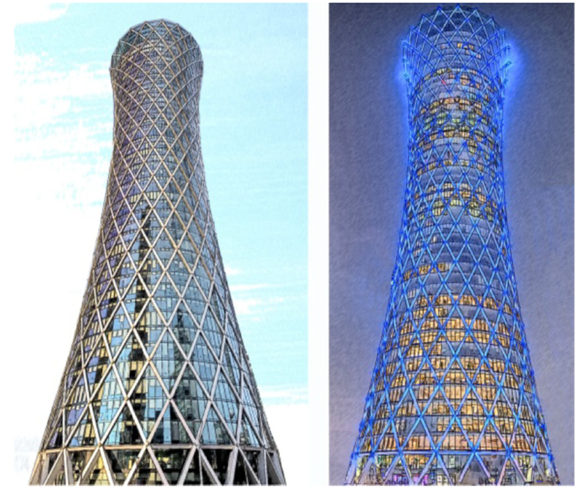
Importantly, articulation and structural details make a difference. For example, the Indigo Icon Tower in Dubai, UAE, uses an A shape that contains a prominent bracing system that adds a landmark quality to the building (Figure 21). NEO Bankside Complex utilizes unique details (e.g., hinges, pins, HSS members with triangular plate “fins,” clevis connectors) that lead to unique visual expression characterized by eloquence and boldness. Finally, lighting systems can help to accentuate the diagrid systems at night. See for example the Tornado Tower (2008) in Doha, Qatar (Figure 22), the Guangzhou International Finance Center (2010) in Guangzhou, China, and the Lotte Super Tower in Seoul, South Korea -- proposed by SOM in 2008 but it is unbuilt [19,20].
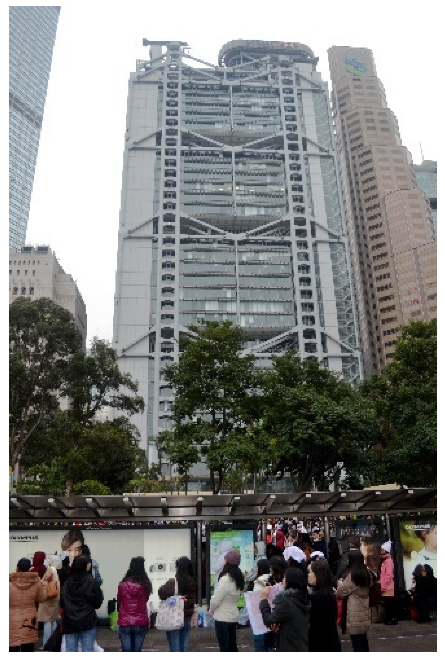
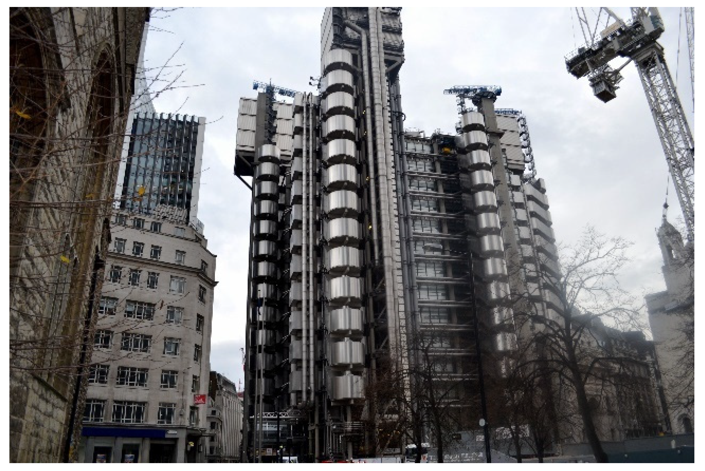
The Structural Expressionism trend continued in the 1980s and inspired a sister trend, the “High-Tech” architecture. Architects Norman Foster and Richard Rogers were among the prominent pioneers. The Hong Kong and Shanghai Bank Corporation (HSBC) Headquarters Building in Hong Kong, Lloyd’s Building (sometimes known as the Inside-Out Building) in London, UK, and the Centre Pompidou in Paris, France are among the best representative examples (Figure 23 and Figure 24). It is important to note that these sister trends are not exchangeable. That is, the High-Tech trend is not strict regarding achieving maximum structural efficiency through an honest display of structural members. The High-Tech movement engages a broader range of technological expressions denoting technological innovations in engineering (mechanical, electrical, and plumbing) and sciences (computer, chemistry, and physics).
Overall, many modernist high-rises exhibited traits of Structural Expression and attempted to “honestly” display their structural systems. However, Structural Expressionism, empowered by its unique aesthetics, underscores innovative structural systems and new building materials. Consequently, the structural expression dictates the façade design and dominates the visual appearance [19]. Of course, we may observe some historical precedents of structural aesthetics in the Gothic cathedrals of the Middle Ages, the work of William Le Baron Jenney and John Wellborn Root, and the theories of French architect Violette-le-Duc. Early projects and architectural theories inspired the Structural Expressionism movement that prevailed in the 1960s and 1970s. The work of Mies van der Rohe, Fazlur R. Khan, and Bruce Graham had a profound and direct influence on it [30]. However, Structural Expressionism waned in the late 1980s, particularly in the early 1990s when Late Modernism and Postmodernism were in vogue.
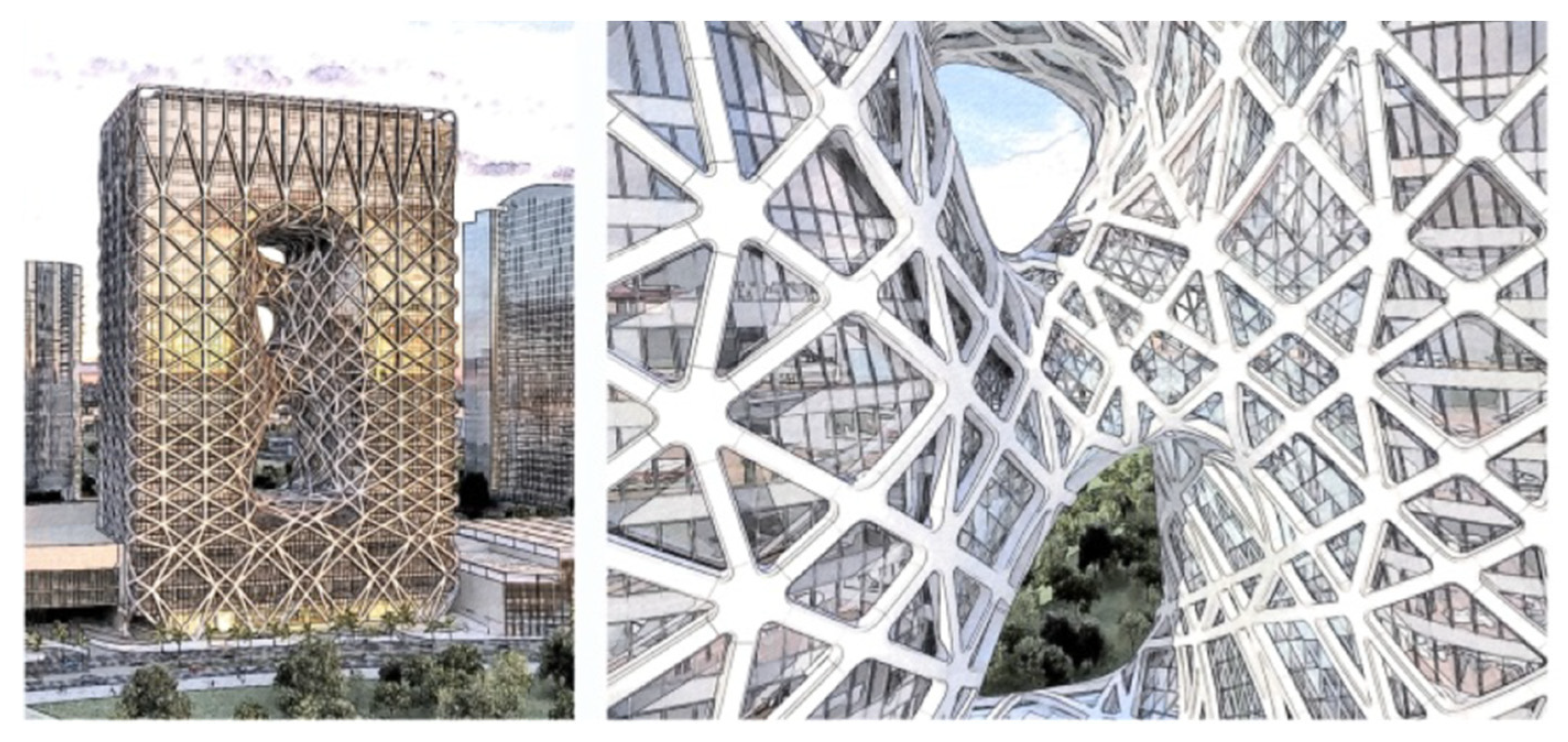
Strikingly, new developments and advancements in diagrid structural systems, explained earlier, have enabled architects and engineers to generate “exotic” forms. An advanced diagrid system allows the creation of an elastic mesh capable of conforming to almost any form or shape. Prominent examples include the Gherkin Building in London, UK; the CCTV Building in Beijing, China; the Capital Gate Building and Al Dar Headquarters in Abu Dhabi, UAE; and the Morpheus Hotel at City of Dreams in Macau, China. The latter building by Zaha Hadid and the CCTV by OMA foster a new trend of diagrid characterized by motion and fluidity through modeling irregular, dynamic forms. Their style gives birth to “diagrid deconstructivism” (Figure 25 and Figure 26). However, unlike mainstream deconstructivism, where the building is decomposed to generate dynamic forms, “diagrid deconstructivism” develops exotic buildings while respecting structural logic and boosting structural efficiency [31]. Further, because of the rise of the Pluralistic architectural style of tall buildings permitting arbitrary, iconic, and “formless” forms embraced by architects, the trend is now toward varied architectural expression based on non-structural considerations. This may, however, be a temporary phase, and the trend will likely change again.
6. Conclusions and Prospects
Construction of tall, supertall, and megatall buildings has increased rapidly in recent years. This study reviews the evolution of tall buildings’ structural systems starting in the late 19th century till the present time. With the advent of advanced building materials, sophisticated computational software, and robust structural systems, we can construct ever taller buildings. The revolutionary height-based structural systems charts, particularly tubular structures, allowed engineers to build taller buildings using less materials. The innovation of composite structures for tall buildings was another milestone that allowed the design of most tall buildings. Expanded system-based charts were later developed, covering previous and latter-day skyscrapers.
Widespread distance working through digital communication has recently slowed the pace of construction of tall commercial buildings due to the incidence of the global pandemic. However, this is expected to gradually change in the post-pandemic period as face-to-face physical human interaction cannot be replaced with a digital exchange. Further innovations and improvements of structural systems will occur for tall buildings as they will continue to be built due to human aspirations and unrelenting demographic expansion in cities. Residential tall buildings will continue to be built unabated.
Funding
This research received no external funding.
Institutional Review Board Statement
Not applicable.
Informed Consent Statement
Not applicable.
Data Availability Statement
Not applicable.
Conflicts of Interest
The authors declare no conflict of interest.
References
- Council on Tall Buildings and Urban Habitat (CTBUH). Available online: https://www.ctbuh.org/resource/height (accessed on 15 May 2022).
- Fenske, G. The First Skyscraper The "First Skyscraper" in the History of Modern Architecture. In First Skyscrapers|Skyscraper Firsts: Considerations of Critical Buildings and Technologies in Skyscraper History; Gray, L., Wood, A., Safarik, D., Eds.; Council on Tall Buildings and Urban Habitat: Chicago, IL, USA, 2020; pp. 66–76. [Google Scholar]
- Ali, M.M.; Moon, K.S. The First Skyscraper: The Case for the Home Insurance Building in Chicago. In First Skyscrapers|Skyscraper Firsts: Considerations of Critical Buildings and Technologies in Skyscraper History; Gray, L., Wood, A., Safarik, D., Eds.; Council on Tall Buildings and Urban Habitat: Chicago, IL, USA, 2020; pp. 77–86. [Google Scholar]
- Tucker, J.B. Skyscrapers: Aiming for 200 Stories. High Technol. 1985, 5, 50–63. [Google Scholar]
- Ali, M.M. Art of the Skyscraper: The Genius of Fazlur Khan. Rizzoli International Publications, Inc.: New York, NY, USA, 2001. [Google Scholar]
- Khan, F.R. Recent Structural Systems in Steel for High-Rise Buildings. In Proceedings of the British Constructional Steelwork Association Conference on Steel in Architecture, London, UK, 24–26 November 1969. [Google Scholar]
- Khan, F.R. Future of High-Rise Structures. Progressive Architecture, 1 January 1972; 78–85. [Google Scholar]
- Blaser, W. Myron Goldsmith: Buildings and Concepts; Rizzoli International Publications: New York, NY, USA, 1987. [Google Scholar]
- Kowalczyk, R.M.; Sinn, R.; Kilmister, M.B. Structural Systems for Tall Buildings; McGraw-Hill: New York, NY, USA, 1995. [Google Scholar]
- Kumar, M.S.; Senthilkumar, R.; Sourabha, L. Seismic performance of special concentric steel braced frames. Structures 2019, 20, 166–175. [Google Scholar] [CrossRef]
- Yurisman, Y.; Budiono, B.; Moestopo, M.; Suarjana, M. Behavior of Shear Link of WF Section with Diagonal Web Stiffener of Eccentrically Braced Frame (EBF) of Steel Structure. ITB J. Eng. Sci. 2010, 42, 103–128. [Google Scholar] [CrossRef]
- Fintel, M. Shear Walls—An Answer for Seismic Resistance? Concr. Int. 1991, 13, 48–53. [Google Scholar]
- Fintel, M. Performance of Buildings with shear walls in Earthquakes of the Last Thirty Years. PCI J. 1995, 40, 62–80. [Google Scholar] [CrossRef]
- Rajendran, R.; Roja Selvaraju, Y. A Review on Performance of Shear Walls. Int. J. Appl. Eng. J. 2016, 11, 369–373. [Google Scholar]
- Khan, F.R.; Sbarounis, J.A. Interaction of Shear Walls and Frames in Concrete Structures under Lateral Loads. J. Am. Soc. Civ. Eng. 1964, 90, 285–335. [Google Scholar]
- Taranath, B.S. Steel, Concrete and Composite Design of Tall Buildings; McGraw-Hill: New York, NY, USA, 1997. [Google Scholar]
- Ali, M.M.; Moon, K.S. Structural Developments in Tall Buildings: Current Trends and Future Prospects. Archit. Sci. Rev. J. 2007, 50, 205–223. [Google Scholar] [CrossRef]
- Glanz, J.; Lipton, E. City in the Sky: The Rise and Fall of World Trade Center; Times Books, Henry Holt and Company: New York, NY, USA, 2003. [Google Scholar]
- Ali, M.M.; Moon, K.S. Advances in Structural Systems for Tall Buildings: Emerging Developments for Contemporary Urban Giants. Build. J. 2018, 8, 104. [Google Scholar] [CrossRef]
- Al-Kodmany, K.; Ali, M.M. An Overview of Structural Developments and Aesthetics of Tall Buildings Using Exterior Bracing and Diagrid Systems. Int. J. High-Rise Build. 2016, 5, 271–291. [Google Scholar] [CrossRef]
- Moon, K.S. Diagrid Structures for Complex-Shaped Tall Buildings. In Proceedings of the Twelfth East Asia-Pacific Conference on Structural Engineering and Construction Precedia Engineering 14; Elsevier: Amsterdam, The Netherlands, 2011. [Google Scholar]
- Boake, T.M. Diagrid Structures: Systems, Connections, Details; Birkhauser Veriag GmbH: Basil, Switzerland, 2014. [Google Scholar]
- Lacidogna, G.; Scaramozzino, D.; Carpinteri, A. Influence of the geometrical shape on the structural behavior of diagrid tall buildings under lateral and torque actions. Dev. Built Environ. 2020, 2, 100009. [Google Scholar] [CrossRef]
- Ali, M.M. Integrated Design of Safe Skyscrapers: Problems, Challenges and Prospects. In Proceedings of the CIB-CTBUH International Conference on Tall Buildings: Strategies for Performance in the Aftermath of the World Trade Center, Kuala Lumpur, Malaysia, 20–23 October 2003. [Google Scholar]
- Al-Kodmany, K. Eco-Towers: Sustainable Cities in the Sky; WIT Press: Southampton, UK, 2015. [Google Scholar]
- Beedle, L.S.; Ali, M.M.; Armstrong, P.J. The Skyscraper and the City: Design, Technology, and Innovation; The Edwin Mellen Press: Lewiston, NY, USA, 2007. [Google Scholar]
- Colaco, J. The Mile-High Dream. Civ. Eng. 1986, 56, 76–78. [Google Scholar]
- Schueller, W. High-Rise Building Structures; John Wiley & Sons: New York, NY, USA, 1977. [Google Scholar]
- Elnimeiri, M. Architecture of Tall Buildings; For Committee 30-Architecture Monograph, Council on Tall Buildings and Urban Habitat, Ali, M.M., Armstrong, P.J., Eds.; McGraw-Hill: New York, NY, USA, 1995; pp. 102–106. [Google Scholar]
- Al-Kodmany, K.; Ali, M.M. The Future of the City: Tall Buildings and Urban Design; WIT Press: Southampton, UK, 2012. [Google Scholar]
- Al-Kodmany, K. Tall Buildings and the City: Improving the Understanding of Placemaking, Imageability, and Tourism; Springer: Berlin/Heidelberg, Germany, 2020. [Google Scholar]
Figure 1.
“Premium for height” by Fazlur R. Khan. (Source: [5], p. 41).
Figure 1.
“Premium for height” by Fazlur R. Khan. (Source: [5], p. 41).

Figure 2.
Types of concentric braces. (Sketch by K. Al-Kodmany; adapted from [10]).
Figure 2.
Types of concentric braces. (Sketch by K. Al-Kodmany; adapted from [10]).

Figure 3.
Types of Eccentrically Braced Frame. (Sketch by K. Al-Kodmany; adapted from [11]).
Figure 3.
Types of Eccentrically Braced Frame. (Sketch by K. Al-Kodmany; adapted from [11]).

Figure 4.
Coupled Shear Wall. (Sketch by K. Al-Kodmany).

Figure 5.
Shear wall (or shear truss)-frame interaction system. (Sketch by K. Al-Kodmany).

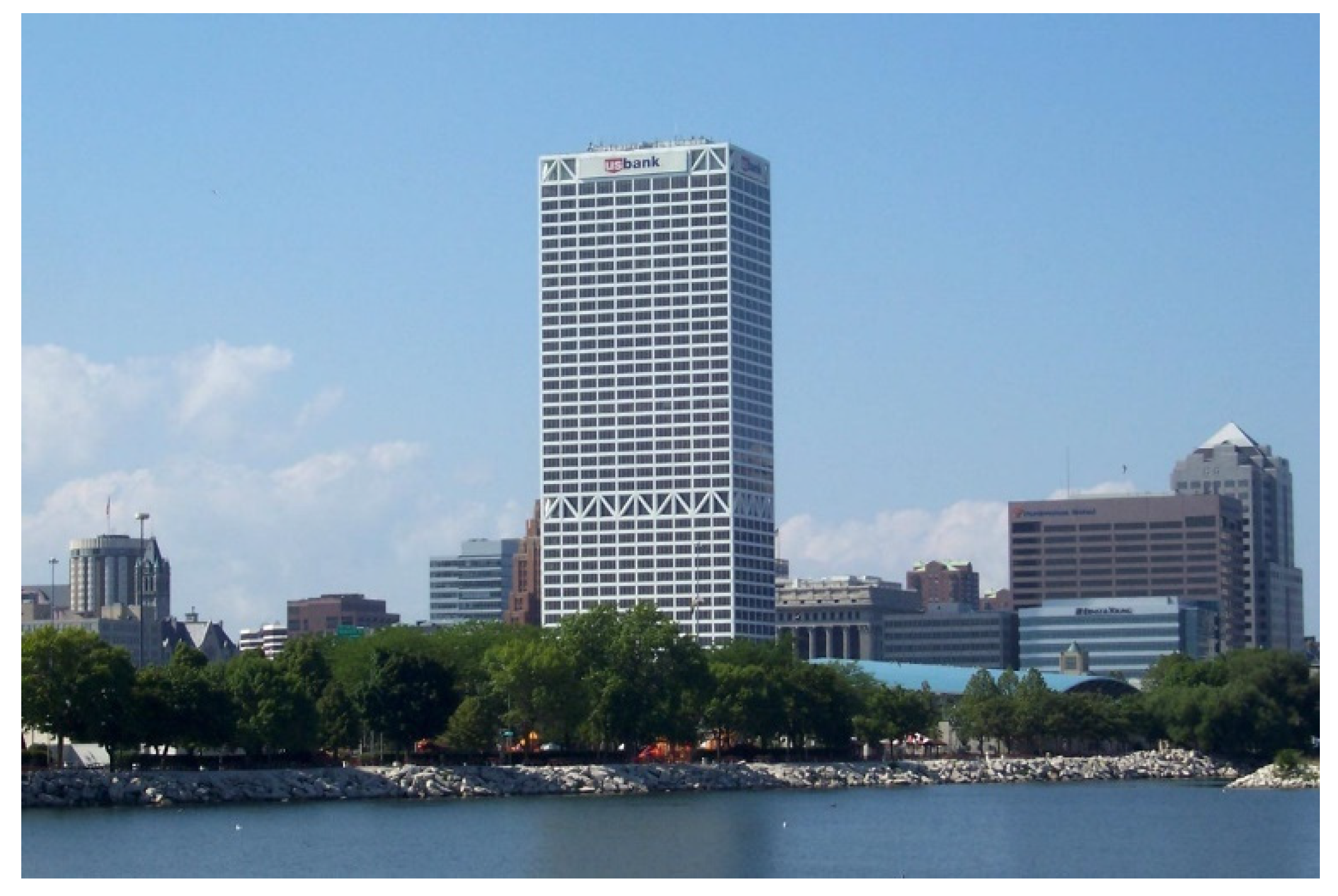
Figure 6.
The US Bank (1973) in Milwaukee, WI, showing the belt trusses. (Source: Wikipedia).

Figure 7.
Shear lag. (Source: [5], p. 45).
Figure 7.
Shear lag. (Source: [5], p. 45).

Figure 8.
Braced Tube building, the John Hancock Center (1970) in Chicago. (Photo by K. Al-Kodmany).
Figure 8.
Braced Tube building, the John Hancock Center (1970) in Chicago. (Photo by K. Al-Kodmany).

Figure 9.
Bundled Tube building. The Sears Tower in Chicago. (Source: [5], pp. 124–125).
Figure 9.
Bundled Tube building. The Sears Tower in Chicago. (Source: [5], pp. 124–125).

Figure 10.
Vertically Stacked Superframes (unbuilt 168-story Chicago World Trade Center). (Source: Wikipedia).
Figure 10.
Vertically Stacked Superframes (unbuilt 168-story Chicago World Trade Center). (Source: Wikipedia).

Figure 11.
The Hearst Tower (2003) in New York City. (Photo by K. Al-Kodmany).

Figure 12.
The Bow Tower (2012) in Calgary, Canada by Norman Foster. (Sketch by K. Al-Kodmany).

Figure 13.
The Capital Gate Building (2011) in Abu Dhabi, UAE. (Photo by K. Al-Kodmany).

Figure 14.
Variation in the bracing angles leads to different structural performance and diagrid expressions. (Sketch by K. Al-Kodmany; adapted from [23]).
Figure 14.
Variation in the bracing angles leads to different structural performance and diagrid expressions. (Sketch by K. Al-Kodmany; adapted from [23]).

Figure 15.
Swiss Re (or Gherkin) Building (2004) in London, UK. (Photo by K. Al-Kodmany).

Figure 16.
Al Dar Headquarters (2010) in Abu Dhabi, UAE. (Photo by K. Al-Kodmany).

Figure 17.
Goldin Finance 117 (unfinished) in Tianjin, China. (Source: Wikipedia).

Figure 18.
Buttressed Core seen in the floor plan of Burj Khalifa in Dubai, UAE. (Source: Wikipedia).
Figure 18.
Buttressed Core seen in the floor plan of Burj Khalifa in Dubai, UAE. (Source: Wikipedia).

Figure 19.
One US Bank Plaza (1976) in Saint Louis, Missouri. (Photo by K. Al-Kodmany).

Figure 20.
Bank of China Tower (1990) in Hong Kong by IMP. (Photo by K. Al-Kodmany).

Figure 21.
The Indigo Icon Tower (2009) in Dubai, UAE. (Photo by K. Al-Kodmany).

Figure 22.
The Tornado Tower (2008) in Doha, Qatar, daytime (left), nighttime (right). (Sketch by K. Al-Kodmany).
Figure 22.
The Tornado Tower (2008) in Doha, Qatar, daytime (left), nighttime (right). (Sketch by K. Al-Kodmany).

Figure 23.
The Hong Kong and Shanghai Bank Corporation (HSBC) Headquarters Building (1985) in Hong Kong. (Photo by K. Al-Kodmany).
Figure 23.
The Hong Kong and Shanghai Bank Corporation (HSBC) Headquarters Building (1985) in Hong Kong. (Photo by K. Al-Kodmany).

Figure 24.
Lloyd’s Building (1986) in London, UK (Center). (Photo by K. Al-Kodmany).

Figure 25.
CCTV Building (2008) in Beijing, China by OMA. It is an example of an innovative diagrid system that improves structural performance and produces “exotic” forms. (Photo by K. Al-Kodmany).
Figure 25.
CCTV Building (2008) in Beijing, China by OMA. It is an example of an innovative diagrid system that improves structural performance and produces “exotic” forms. (Photo by K. Al-Kodmany).

Figure 26.
Morpheus Hotel (2018) at City of Dreams in Macau, China by Zaha Hadid. It is an example of an “exotic” diagrid structure. The right image zooms in on the dynamic portion of the diagrid. (Sketch by K. Al-Kodmany).
Figure 26.
Morpheus Hotel (2018) at City of Dreams in Macau, China by Zaha Hadid. It is an example of an “exotic” diagrid structure. The right image zooms in on the dynamic portion of the diagrid. (Sketch by K. Al-Kodmany).

Publisher’s Note: MDPI stays neutral with regard to jurisdictional claims in published maps and institutional affiliations. |
© 2022 by the authors. Licensee MDPI, Basel, Switzerland. This article is an open access article distributed under the terms and conditions of the Creative Commons Attribution (CC BY) license (https://creativecommons.org/licenses/by/4.0/).
Share and Cite
MDPI and ACS Style
Ali, M.M.; Al-Kodmany, K. Structural Systems for Tall Buildings. Encyclopedia 2022, 2, 1260-1286. https://doi.org/10.3390/encyclopedia2030085
AMA Style
Ali MM, Al-Kodmany K. Structural Systems for Tall Buildings. Encyclopedia. 2022; 2(3):1260-1286. https://doi.org/10.3390/encyclopedia2030085
Chicago/Turabian StyleAli, Mir M., and Kheir Al-Kodmany. 2022. "Structural Systems for Tall Buildings" Encyclopedia 2, no. 3: 1260-1286. https://doi.org/10.3390/encyclopedia2030085