
Enhanced Gypsum Boards with Activated Carbon Composites and Phase Change Materials for Advanced Thermal Energy Storage and Electromagnetic Interference Shielding Properties

 ,
,  ,
,  , , , , , and
Abstract
:1. Introduction
2. Materials and Methods
2.1. Materials
2.2. Activated Carbon Production
2.3. Paraffin Encapsulation
2.4. Gypsum Board Production
2.5. Leaching Tests
2.6. Density Measurements
2.7. X-ray Computed Microtomography (Micro CT)
2.8. Thermogravimetric Analysis (TGA)
2.9. Thermal Properties
2.10. Mechanical Properties
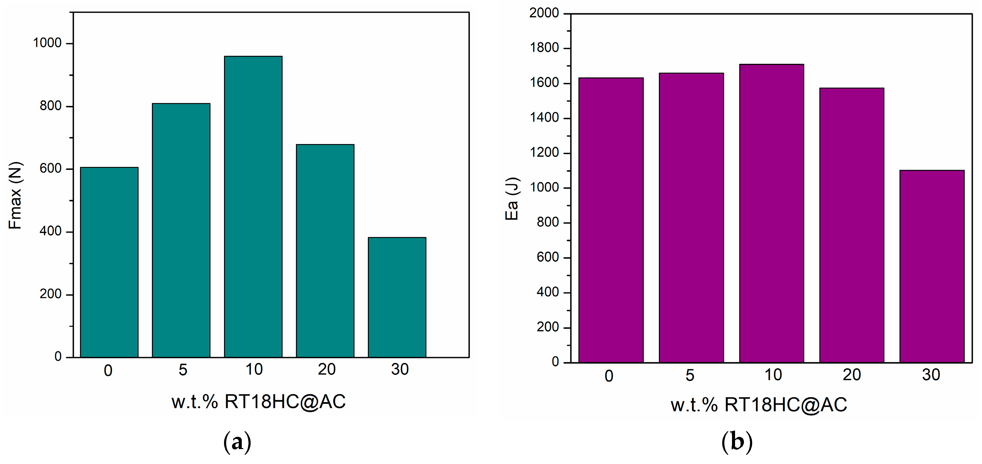
2.10.1. Low-Velocity Impact Testing
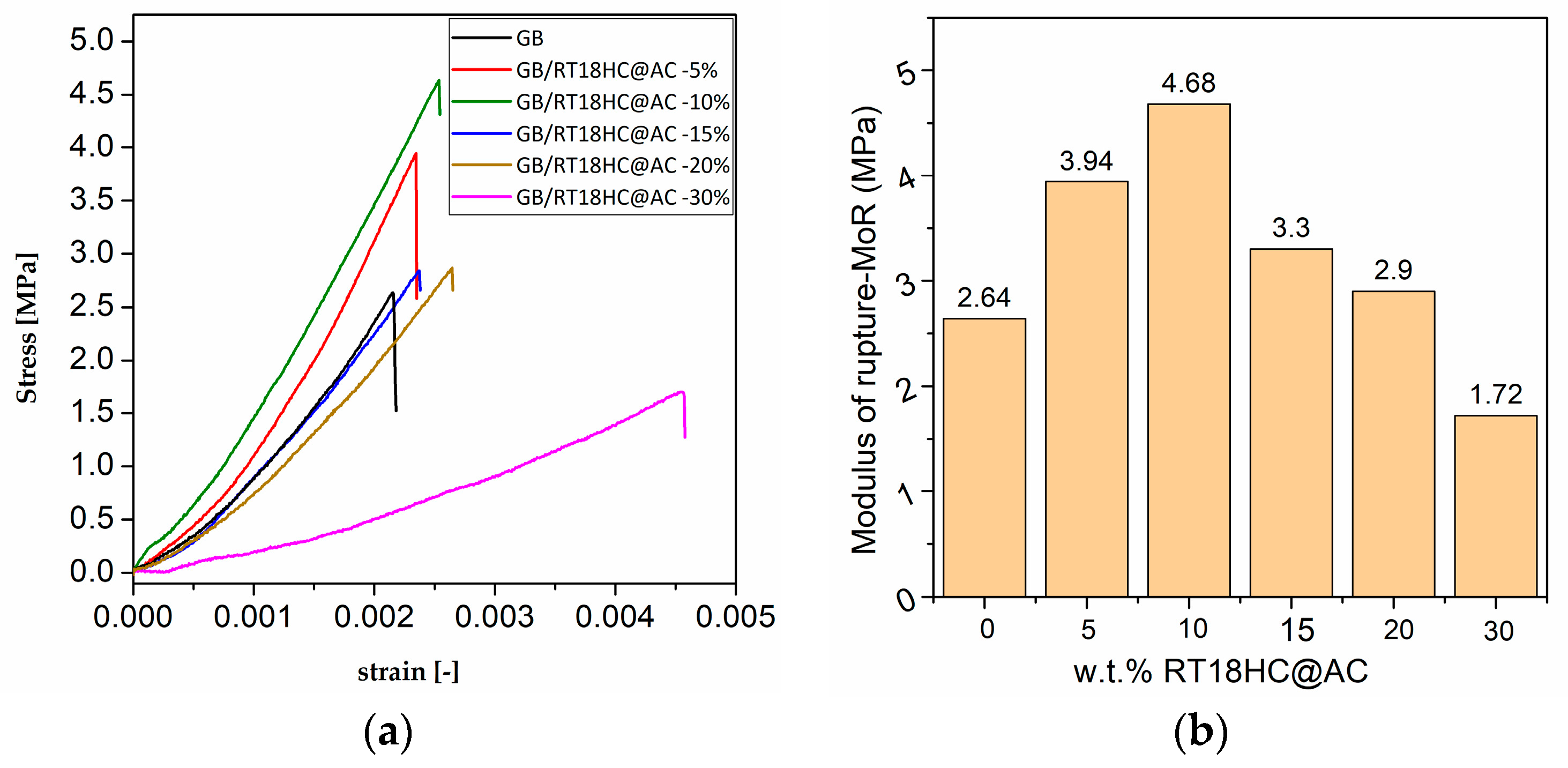
2.10.2. Modulus of Rupture, MOR
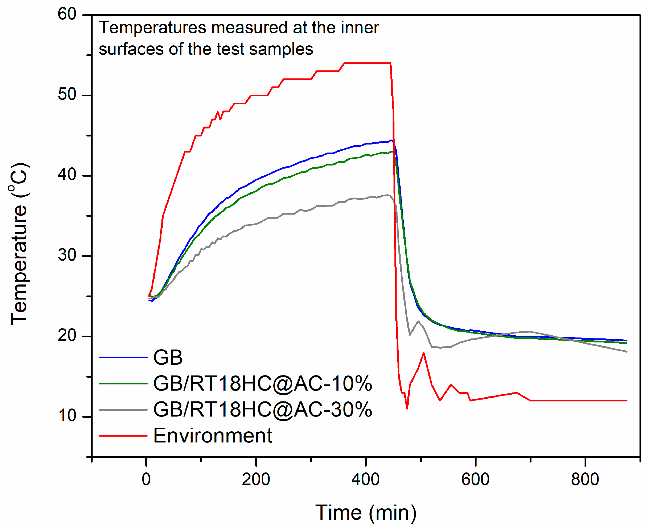
2.11. Thermal Performance Measurements
2.12. Electromagnetic Interference (EMI) Shielding Properties
3. Results and Discussion
3.1. Characterization of RT18HC@AC Filler
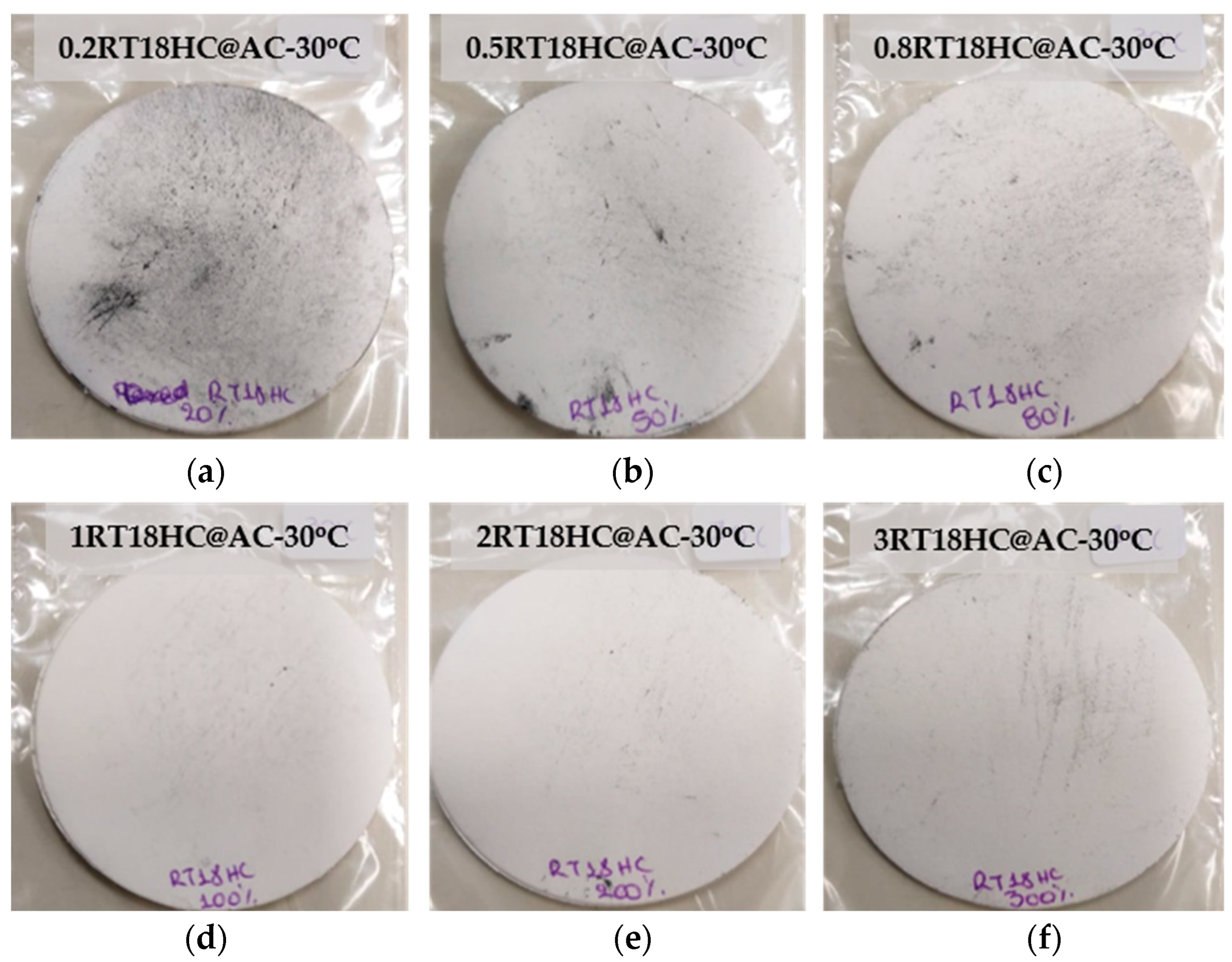
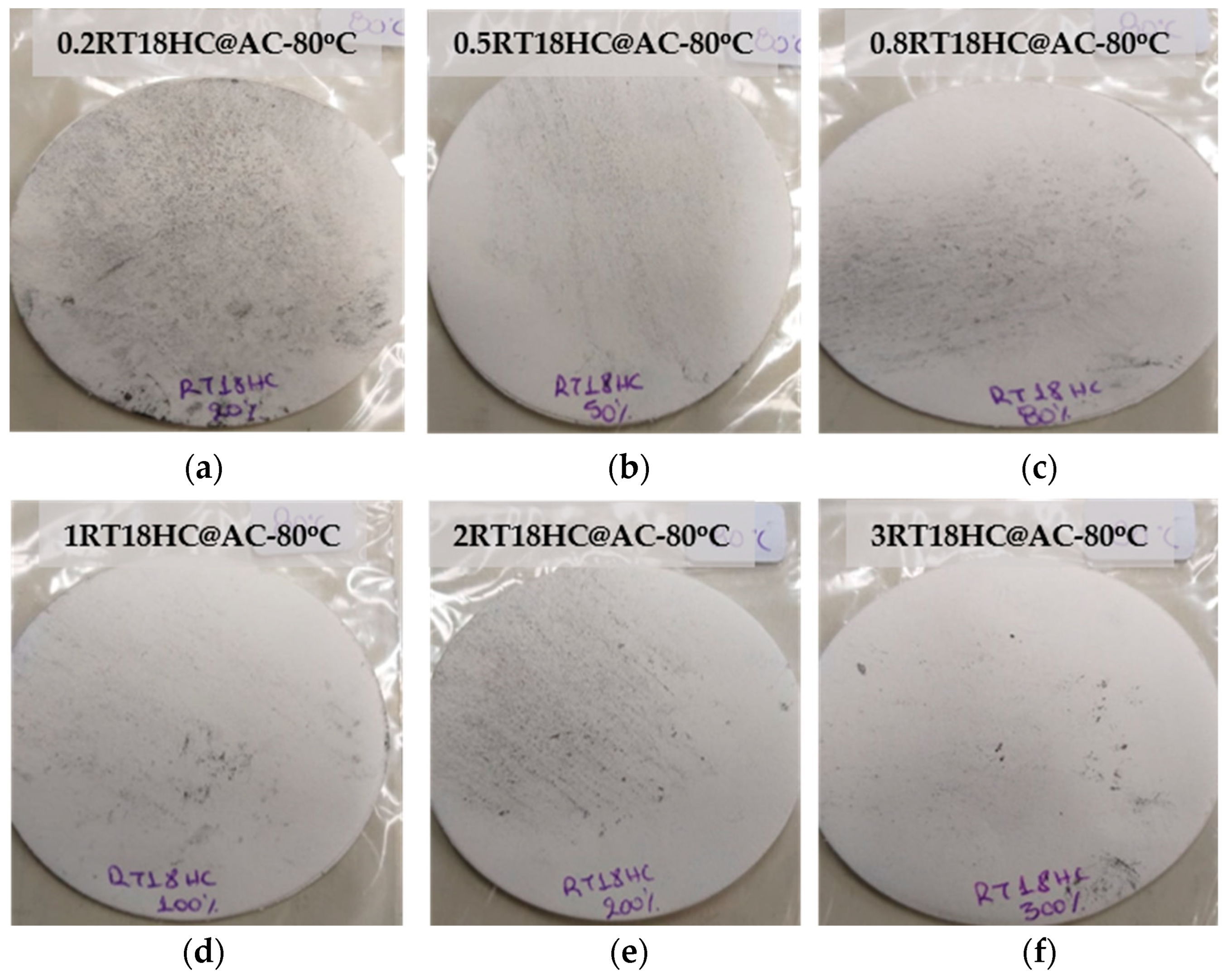
3.1.1. Leaching Tests for RT18HC@AC Filler
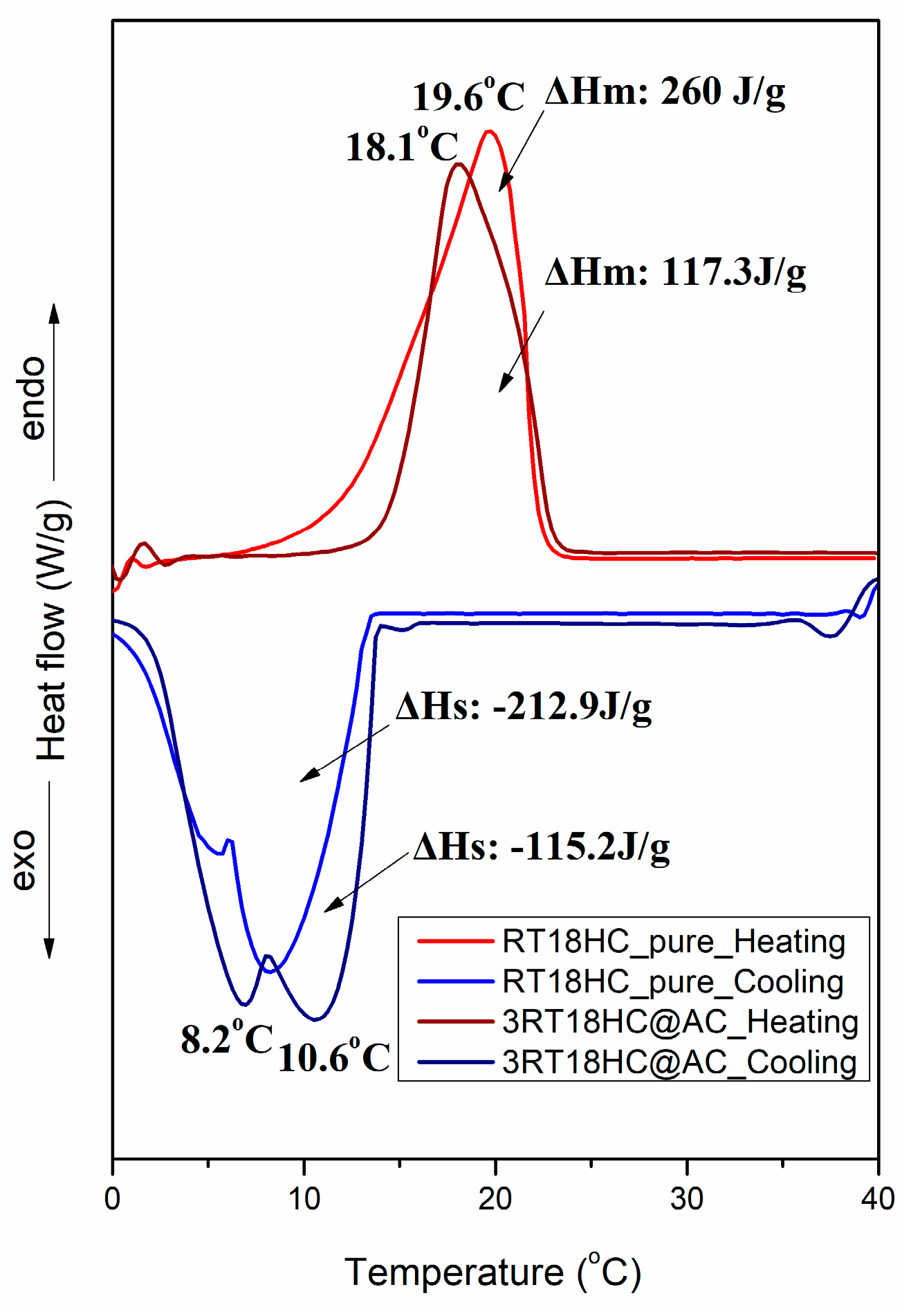
3.1.2. Thermal Properties of AC-RT18HC Filler
3.2. Characterization of Gypsum/RT18HC@AC Composite Boards
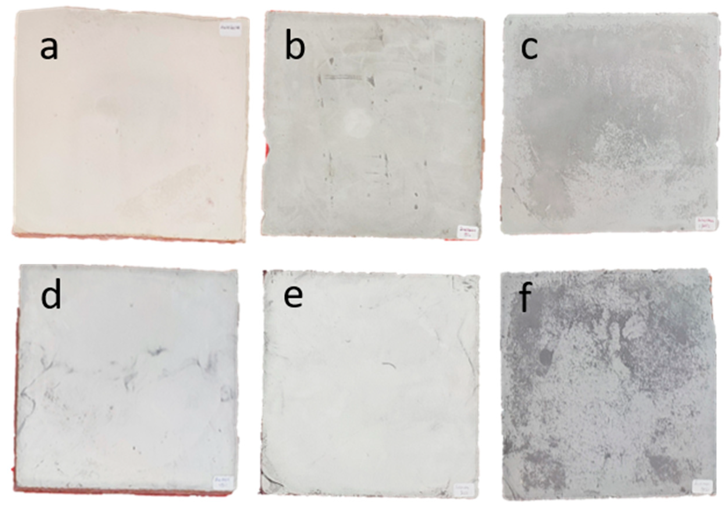
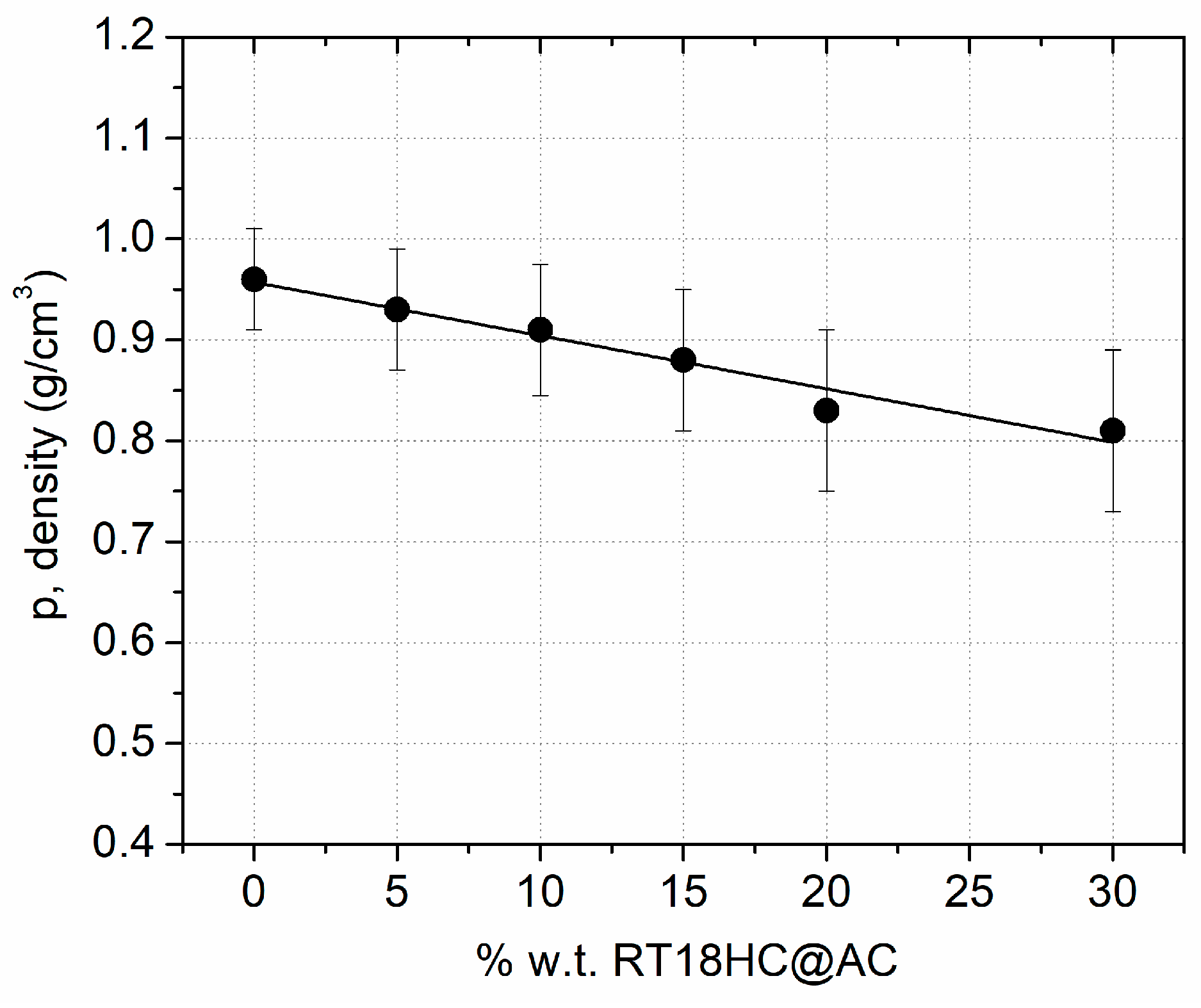
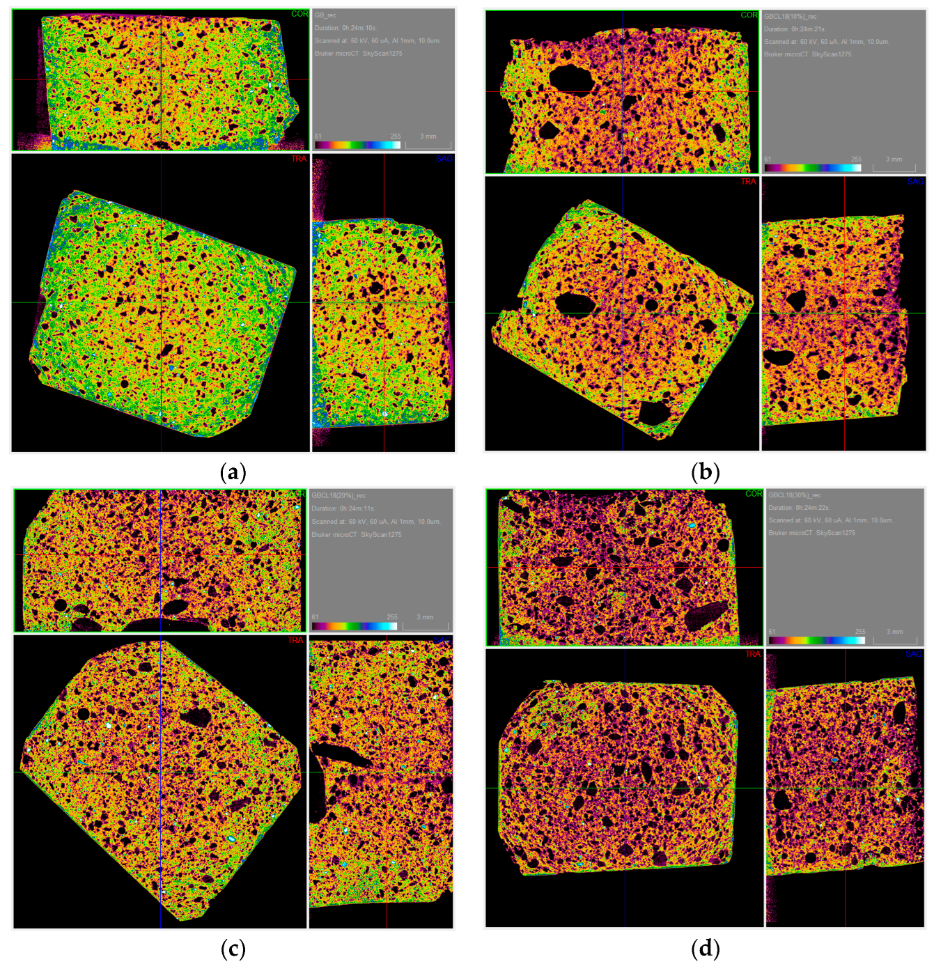
3.2.1. Density and Microtomography Results for GB/RT18HC@AC Composite Boards
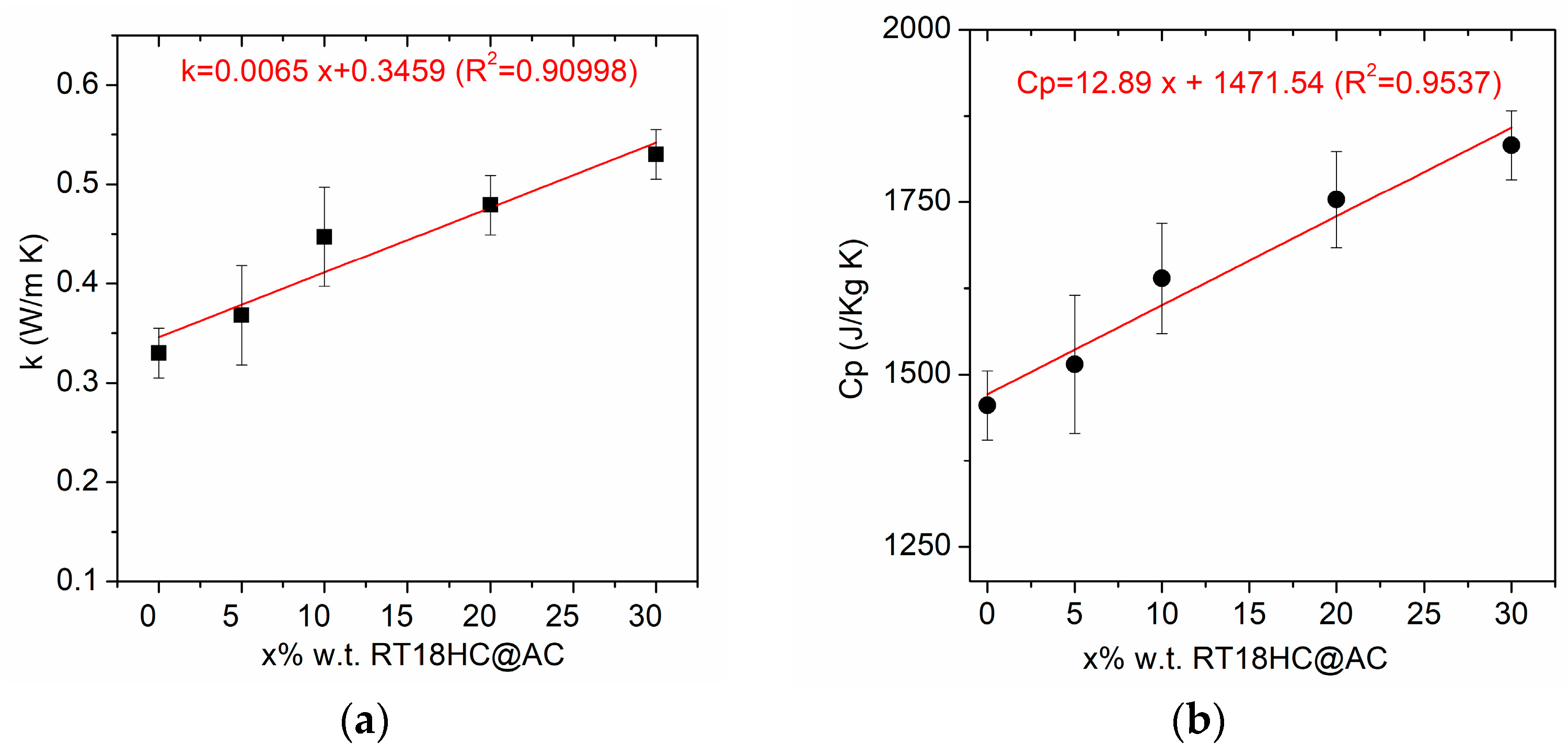
3.2.2. Thermal Properties of GB/RT18HC@AC Composite Boards
3.2.3. Mechanical Properties of GB/RT18HC@AC Composite Boards
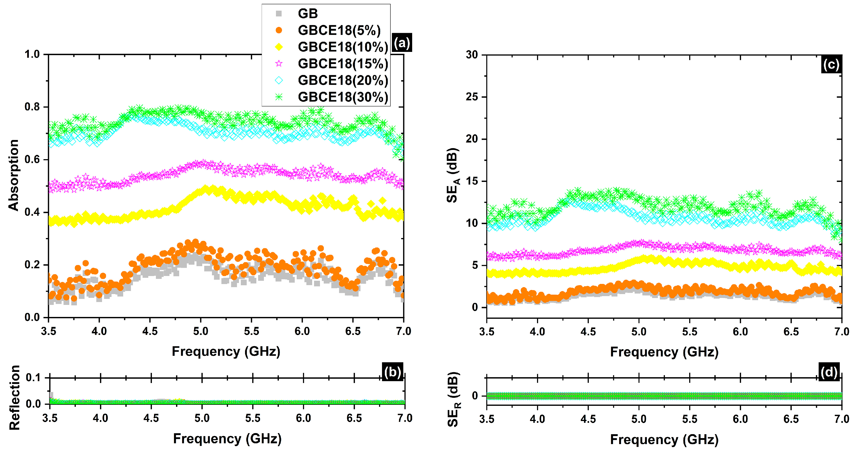
3.2.4. EMI Shielding Properties for GB/RT18HC@AC Composite Boards
3.2.5. Thermal Performance Measurements
4. Conclusions
Supplementary Materials
Author Contributions
Funding
Data Availability Statement
Conflicts of Interest
References
- Al-Absi, Z.A.; Mohd Isa, M.H.; Ismail, M. Phase Change Materials (PCMs) and Their Optimum Position in Building Walls. Sustainability 2020, 12, 1294. [Google Scholar] [CrossRef]
- da Cunha, S.R.L.; de Aguiar, J.L.B. Phase Change Materials and Energy Efficiency of Buildings: A Review of Knowledge. J. Energy Storage 2020, 27, 101083. [Google Scholar] [CrossRef]
- Zachariah, S.M.; Antony, T.; Grohens, Y.; Thomas, S. From Waste to Wealth: A Critical Review on Advanced Materials for EMI Shielding. J. Appl. Polym. Sci. 2022, 139, e52974. [Google Scholar] [CrossRef]
- Wu, N.; Hu, Q.; Wei, R.; Mai, X.; Naik, N.; Pan, D.; Guo, Z.; Shi, Z. Review on the Electromagnetic Interference Shielding Properties of Carbon Based Materials and Their Novel Composites: Recent Progress, Challenges and Prospects. Carbon 2021, 176, 88–105. [Google Scholar] [CrossRef]
- Vaishnav, K.; Lazarus, G.P.; Bansal, S.; Hooda, Y. Review on Thermal Energy Efficiency Using Gypsum Integrated Phase Change Materials in Buildings. In Proceedings of the Advances in Construction Materials and Sustainable Environment; Gupta, A.K., Shukla, S.K., Azamathulla, H., Eds.; Springer: Singapore, 2022; pp. 305–319. [Google Scholar]
- Sharifi, N.P.; Shaikh, A.A.N.; Sakulich, A.R. Application of Phase Change Materials in Gypsum Boards to Meet Building Energy Conservation Goals. Energy Build. 2017, 138, 455–467. [Google Scholar] [CrossRef]
- Pasupathy, A.; Velraj, R.; Seeniraj, R.V. Phase Change Material-Based Building Architecture for Thermal Management in Residential and Commercial Establishments. Renew. Sustain. Energy Rev. 2008, 12, 39–64. [Google Scholar] [CrossRef]
- Yang, A.-S.; Cai, T.-Y.; Su, L.; Li, Y.-S.; He, F.-F.; Zhang, Q.-P.; Zhou, Y.-L.; He, R.; Zhang, K.; Yang, W.-B. Review on Organic Phase Change Materials for Sustainable Energy Storage. Sustain. Energy Fuels 2022, 6, 5045–5071. [Google Scholar] [CrossRef]
- Rashid, F.L.; Al-Obaidi, M.A.; Dulaimi, A.; Bernardo, L.F.A.; Eleiwi, M.A.; Mahood, H.B.; Hashim, A. A Review of Recent Improvements, Developments, Effects, and Challenges on Using Phase-Change Materials in Concrete for Thermal Energy Storage and Release. J. Compos. Sci. 2023, 7, 352. [Google Scholar] [CrossRef]
- Liu, X.; Yang, F.; Li, M.; Sun, C.; Wu, Y. Development of Cost-Effective PCM-Carbon Foam Composites for Thermal Energy Storage. Energy Rep. 2022, 8, 1696–1703. [Google Scholar] [CrossRef]
- Gioti, C.; Karakassides, A.; Asimakopoulos, G.; Baikousi, M.; Salmas, C.E.; Viskadourakis, Z.; Kenanakis, G.; Karakassides, M.A. Multifunctional Carbon-Based Hybrid Foams for Shape-Stabilization of Phase Change Materials, Thermal Energy Storage, and Electromagnetic Interference Shielding Functions. Micro 2022, 2, 390–409. [Google Scholar] [CrossRef]
- Rathore, P.K.S.; Shukla, S.K. Enhanced Thermophysical Properties of Organic PCM through Shape Stabilization for Thermal Energy Storage in Buildings: A State of the Art Review. Energy Build. 2021, 236, 110799. [Google Scholar] [CrossRef]
- Abdeali, G.; Bahramian, A.R.; Abdollahi, M. Review on Nanostructure Supporting Material Strategies in Shape-Stabilized Phase Change Materials. J. Energy Storage 2020, 29, 101299. [Google Scholar] [CrossRef]
- Khadiran, T.; Hussein, M.Z.; Zainal, Z.; Rusli, R. Shape-Stabilised n-Octadecane/Activated Carbon Nanocomposite Phase Change Material for Thermal Energy Storage. J. Taiwan Inst. Chem. Eng. 2015, 55, 189–197. [Google Scholar] [CrossRef]
- Feng, L.; Zheng, J.; Yang, H.; Guo, Y.; Li, W.; Li, X. Preparation and Characterization of Polyethylene Glycol/Active Carbon Composites as Shape-Stabilized Phase Change Materials. Sol. Energy Mater. Sol. Cells 2011, 95, 644–650. [Google Scholar] [CrossRef]
- Chen, Z.; Shan, F.; Cao, L.; Fang, G. Synthesis and Thermal Properties of Shape-Stabilized Lauric Acid/Activated Carbon Composites as Phase Change Materials for Thermal Energy Storage. Sol. Energy Mater. Sol. Cells 2012, 102, 131–136. [Google Scholar] [CrossRef]
- Xia, L.; Zhang, P.; Wang, R.Z. Preparation and Thermal Characterization of Expanded Graphite/Paraffin Composite Phase Change Material. Carbon 2010, 48, 2538–2548. [Google Scholar] [CrossRef]
- Zhang, Z.; Zhang, N.; Peng, J.; Fang, X.; Gao, X.; Fang, Y. Preparation and Thermal Energy Storage Properties of Paraffin/Expanded Graphite Composite Phase Change Material. Appl. Energy 2012, 91, 426–431. [Google Scholar] [CrossRef]
- Li, B.; Liu, T.; Hu, L.; Wang, Y.; Nie, S. Facile Preparation and Adjustable Thermal Property of Stearic Acid–Graphene Oxide Composite as Shape-Stabilized Phase Change Material. Chem. Eng. J. 2013, 215–216, 819–826. [Google Scholar] [CrossRef]
- Mehrali, M.; Latibari, S.T.; Mehrali, M.; Metselaar, H.S.C.; Silakhori, M. Shape-Stabilized Phase Change Materials with High Thermal Conductivity Based on Paraffin/Graphene Oxide Composite. Energy Convers. Manag. 2013, 67, 275–282. [Google Scholar] [CrossRef]
- Jiang, T.; Zhang, Y.; Olayiwola, S.; Lau, C.; Fan, M.; Ng, K.; Tan, G. Biomass-Derived Porous Carbons Support in Phase Change Materials for Building Energy Efficiency: A Review. Mater. Today Energy 2022, 23, 100905. [Google Scholar] [CrossRef]
- Li, M.; Mu, B. Effect of Different Dimensional Carbon Materials on the Properties and Application of Phase Change Materials: A Review. Appl. Energy 2019, 242, 695–715. [Google Scholar] [CrossRef]
- Srinivasaraonaik, B.; Singh, L.P.; Sinha, S.; Tyagi, I.; Rawat, A. Studies on the Mechanical Properties and Thermal Behavior of Microencapsulated Eutectic Mixture in Gypsum Composite Board for Thermal Regulation in the Buildings. J. Build. Eng. 2020, 31, 101400. [Google Scholar] [CrossRef]
- Khadiran, T.; Hussein, M.Z.; Zainal, Z.; Rusli, R. Activated Carbon Derived from Peat Soil as a Framework for the Preparation of Shape-Stabilized Phase Change Material. Energy 2015, 82, 468–478. [Google Scholar] [CrossRef]
- Hussain, S.I.; Dinesh, R.; Roseline, A.A.; Dhivya, S.; Kalaiselvam, S. Enhanced Thermal Performance and Study the Influence of Sub Cooling on Activated Carbon Dispersed Eutectic PCM for Cold Storage Applications. Energy Build. 2017, 143, 17–24. [Google Scholar] [CrossRef]
- Chin, C.O.; Yang, X.; Paul, S.C.; Susilawati; Wong, L.S.; Kong, S.Y. Development of Thermal Energy Storage Lightweight Concrete Using Paraffin-Oil Palm Kernel Shell-Activated Carbon Composite. J. Clean. Prod. 2020, 261, 121227. [Google Scholar] [CrossRef]
- Mert, H.H.; Eslek, A.; Mert, E.H.; Mert, M.S. Preparation and Characterization of Shape-Stable Bio-Based Composite Phase Change Materials for Thermal Energy Storage: Coconut Oil/Activated Carbon from Cherry Stones Doped Composites. Energy Sources Part Recovery Util. Environ. Eff. 2022, 44, 5381–5397. [Google Scholar] [CrossRef]
- Atinafu, D.G.; Dong, W.; Wang, C.; Wang, G. Synthesis of Porous Carbon from Cotton Using an Mg(OH)2 Template for Form-Stabilized Phase Change Materials with High Encapsulation Capacity, Transition Enthalpy and Reliability. J. Mater. Chem. A 2018, 6, 8969–8977. [Google Scholar] [CrossRef]
- Lv, L.; Wang, J.; Ji, M.; Zhang, Y.; Huang, S.; Cen, K.; Zhou, H. Effect of Structural Characteristics and Surface Functional Groups of Biochar on Thermal Properties of Different Organic Phase Change Materials: Dominant Encapsulation Mechanisms. Renew. Energy 2022, 195, 1238–1252. [Google Scholar] [CrossRef]
- Sarabandi, D.; Roudini, G.; Barahuie, F. Activated Carbon Derived from Pine Cone as a Framework for the Preparation of N-Heptadecane Nanocomposite for Thermal Energy Storage. J. Energy Storage 2019, 24, 100795. [Google Scholar] [CrossRef]
- Lv, L.; Huang, S.; Zhou, C.; Ma, W. Biochar Activated by Potassium Carbonate to Load Organic Phase Change Material: Better Performance and Environmental Friendliness. Ind. Crops Prod. 2023, 204, 117184. [Google Scholar] [CrossRef]
- Zeng, S.; Huang, Z.; Jiang, H.; Li, Y. From Waste to Wealth: A Lightweight and Flexible Leather Solid Waste/Polyvinyl Alcohol/Silver Paper for Highly Efficient Electromagnetic Interference Shielding. ACS Appl. Mater. Interfaces 2020, 12, 52038–52049. [Google Scholar] [CrossRef] [PubMed]
- Ma, X.; Shen, B.; Zhang, L.; Chen, Z.; Liu, Y.; Zhai, W.; Zheng, W. Novel Straw-Derived Carbon Materials for Electromagnetic Interference Shielding: A Waste-to-Wealth and Sustainable Initiative. ACS Sustain. Chem. Eng. 2019, 7, 9663–9670. [Google Scholar] [CrossRef]
- Bai, Z.; Zhao, B.; Deng, J.; Ren, Y.; Li, Y.; Wang, R.; Zeng, F.; Guo, X.; Zhang, R. Light-Weight and High-Efficiency Electromagnetic Wave Shielding Properties Based on Waste Straw Porous Carbon. J. Mater. Sci. Mater. Electron. 2020, 31, 4963–4971. [Google Scholar] [CrossRef]
- Zhang, Y.; Yang, Z.; Yu, Y.; Wen, B.; Liu, Y.; Qiu, M. Tunable Electromagnetic Interference Shielding Ability in a One-Dimensional Bagasse Fiber/Polyaniline Heterostructure. ACS Appl. Polym. Mater. 2019, 1, 737–745. [Google Scholar] [CrossRef]
- Aslam, M.A.; Ding, W.; ur Rehman, S.; Hassan, A.; Bian, Y.; Liu, Q.; Sheng, Z. Low Cost 3D Bio-Carbon Foams Obtained from Wheat Straw with Broadened Bandwidth Electromagnetic Wave Absorption Performance. Appl. Surf. Sci. 2021, 543, 148785. [Google Scholar] [CrossRef]
- Zhang, Y.; Yang, Z.; Pan, T.; Gao, H.; Guan, H.; Xu, J.; Zhang, Z. Construction of Natural Fiber/Polyaniline Core-Shell Heterostructures with Tunable and Excellent Electromagnetic Shielding Capability via a Facile Secondary Doping Strategy. Compos. Part Appl. Sci. Manuf. 2020, 137, 105994. [Google Scholar] [CrossRef]
- Khasnabis, S.; Jois HS, M.; Bora, P.J.; Ramamurthy, P.C. Comparative Studies on Physical and Chemical Routes for Animal Waste-Derived Activated Carbon for Microwave Absorption in the X-Band. J. Mater. Sci. Mater. Electron. 2022, 33, 3425–3437. [Google Scholar] [CrossRef]
- Borreguero, A.M.; Garrido, I.; Valverde, J.L.; Rodríguez, J.F.; Carmona, M. Development of Smart Gypsum Composites by Incorporating Thermoregulating Microcapsules. Energy Build. 2014, 76, 631–639. [Google Scholar] [CrossRef]
- Yaras, A.; Ustaoglu, A.; Gencel, O.; Sarı, A.; Hekimoğlu, G.; Sutcu, M.; Erdogmus, E.; Kaplan, G.; Bayraktar, O.Y. Characteristics, Energy Saving and Carbon Emission Reduction Potential of Gypsum Wallboard Containing Phase Change Material. J. Energy Storage 2022, 55, 105685. [Google Scholar] [CrossRef]
- Serrano, S.; Barreneche, C.; Inés Fernández, A.; Farid, M.M.; Cabeza, L.F. Composite Gypsum Containing Fatty-Ester PCM to Be Used as Constructive System: Thermophysical Characterization of Two Shape-Stabilized Formulations. Energy Build. 2015, 86, 190–193. [Google Scholar] [CrossRef]
- Li, C.; Yu, H.; Song, Y.; Liu, Z. Novel Hybrid Microencapsulated Phase Change Materials Incorporated Wallboard for Year-Long Year Energy Storage in Buildings. Energy Convers. Manag. 2019, 183, 791–802. [Google Scholar] [CrossRef]
- Zhang, Y.; Tao, W.; Wang, K.; Li, D. Analysis of Thermal Properties of Gypsum Materials Incorporated with Microencapsulated Phase Change Materials Based on Silica. Renew. Energy 2020, 149, 400–408. [Google Scholar] [CrossRef]
- Bake, M.; Shukla, A.; Liu, S. Development of Gypsum Plasterboard Embodied with Microencapsulated Phase Change Material for Energy Efficient Buildings. Mater. Sci. Energy Technol. 2021, 4, 166–176. [Google Scholar] [CrossRef]
- Fei, H.; Wang, L.; He, Q.; Du, W.; Gu, Q.; Pan, Y. Preparation and Properties of a Composite Phase Change Energy Storage Gypsum Board Based on Capric Acid-Paraffin/Expanded Graphite. ACS Omega 2021, 6, 6144–6152. [Google Scholar] [CrossRef] [PubMed]
- Chen, C.; Wang, X.; Ma, F.; Wang, Y.; Jiu, S.; Chen, Y. Preparation and Characterization of Modified Activated Carbon-Based Shape Stabilized Eutectic Phase Change Materials for Gypsum Composites Application. Constr. Build. Mater. 2023, 369, 130551. [Google Scholar] [CrossRef]
- Zhang, H.; Xu, Q.; Zhao, Z.; Zhang, J.; Sun, Y.; Sun, L.; Xu, F.; Sawada, Y. Preparation and Thermal Performance of Gypsum Boards Incorporated with Microencapsulated Phase Change Materials for Thermal Regulation. Sol. Energy Mater. Sol. Cells 2012, 102, 93–102. [Google Scholar] [CrossRef]
- Toppi, T.; Mazzarella, L. Gypsum Based Composite Materials with Micro-Encapsulated PCM: Experimental Correlations for Thermal Properties Estimation on the Basis of the Composition. Energy Build. 2013, 57, 227–236. [Google Scholar] [CrossRef]
- Cui, H.; Tang, W.; Qin, Q.; Xing, F.; Liao, W.; Wen, H. Development of Structural-Functional Integrated Energy Storage Concrete with Innovative Macro-Encapsulated PCM by Hollow Steel Ball. Appl. Energy 2017, 185, 107–118. [Google Scholar] [CrossRef]
- Asimakopoulos, G.; Baikousi, M.; Kostas, V.; Papantoniou, M.; Bourlinos, A.B.; Zbořil, R.; Karakassides, M.A.; Salmas, C.E. Nanoporous Activated Carbon Derived via Pyrolysis Process of Spent Coffee: Structural Characterization. Investigation of Its Use for Hexavalent Chromium Removal. Appl. Sci. 2020, 10, 8812. [Google Scholar] [CrossRef]
- Robert, U.W.; Etuk, S.E.; Agbasi, O.E. Modified Water Displacement Method and Its Use for Determination of Bulk Density of Porous Materials. J. Renew. Energy Mech. REM 2019, 2, 1–16. [Google Scholar] [CrossRef]
- Standard Test Method for Measurement of Thermal Effusivity of Fabrics Using a Modified Transient Plane Source (MTPS) Instrument. Available online: https://www.astm.org/d7984-21.html (accessed on 18 December 2023).
- ASTM Standard C90-15; Standard Specification for Loadbearing Concrete Masonry Units. ASTM International: West Conshohocken, PA, USA, 2015.
- Standard Test Method for Flexural Strength of Concrete (Using Simple Beam with Center-Point Loading). Available online: https://www.astm.org/c0293_c0293m-16.html (accessed on 19 December 2023).
- RT GmbH. RT18HC; RT GmbH: Giessen, Germany, 2020. [Google Scholar]
- Kim, D.; Jung, J.; Kim, Y.; Lee, M.; Seo, J.; Khan, S.B. Structure and Thermal Properties of Octadecane/Expanded Graphite Composites as Shape-Stabilized Phase Change Materials. Int. J. Heat Mass Transf. 2016, 95, 735–741. [Google Scholar] [CrossRef]
- Standard EN 13279-1; Gypsum Binders and Gypsum Plasters. Part 1: Definitions and Requirements. UNE: Madrid, Spain, 2009.
- López Pedrajas, D.; Borreguero Simón, A.M.; Sáenz, I.G.; Ramos, F.J.; Rodríguez Romero, J.F.; Carmona Franco, M. Thermoregulating Gypsums by Using Nanoencapsulated Phase Change Material Slurry. J. Therm. Anal. Calorim. 2022, 147, 9959–9973. [Google Scholar] [CrossRef]
- Verma, M.; Singh, A.P.; Sambyal, P.; Singh, B.P.; Dhawan, S.K.; Choudhary, V. Barium Ferrite Decorated Reduced Graphene Oxide Nanocomposite for Effective Electromagnetic Interference Shielding. Phys. Chem. Chem. Phys. 2014, 17, 1610–1618. [Google Scholar] [CrossRef] [PubMed]
- Zheng, X.; Tang, J.; Cheng, L.; Yang, H.; Zou, L.; Li, C. Superhydrophobic Hollow Magnetized Fe3O4 Nanospheres/MXene Fabrics for Electromagnetic Interference Shielding. J. Alloys Compd. 2023, 934, 167964. [Google Scholar] [CrossRef]
- Zheng, X.; Cao, W.; Hong, X.; Zou, L.; Liu, Z.; Wang, P.; Li, C. Versatile Electronic Textile Enabled by a Mixed-Dimensional Assembly Strategy. Small 2023, 19, 2208134. [Google Scholar] [CrossRef] [PubMed]
- Ameli, A.; Jung, P.U.; Park, C.B. Electrical Properties and Electromagnetic Interference Shielding Effectiveness of Polypropylene/Carbon Fiber Composite Foams. Carbon 2013, 60, 379–391. [Google Scholar] [CrossRef]
- Al-Saleh, M.H.; Saadeh, W.H.; Sundararaj, U. EMI Shielding Effectiveness of Carbon Based Nanostructured Polymeric Materials: A Comparative Study. Carbon 2013, 60, 146–156. [Google Scholar] [CrossRef]
- Al-Saleh, M.H.; Gelves, G.A.; Sundararaj, U. Copper Nanowire/Polystyrene Nanocomposites: Lower Percolation Threshold and Higher EMI Shielding. Compos. Part Appl. Sci. Manuf. 2011, 42, 92–97. [Google Scholar] [CrossRef]
- Viskadourakis, Z.; Vasilopoulos, K.C.; Economou, E.N.; Soukoulis, C.M.; Kenanakis, G. Electromagnetic Shielding Effectiveness of 3D Printed Polymer Composites. Appl. Phys. Mater. Sci. Process. 2017, 123, 736. [Google Scholar] [CrossRef]
- Zheng, X.; Hu, Q.; Wang, Z.; Nie, W.; Wang, P.; Li, C. Roll-to-Roll Layer-by-Layer Assembly Bark-Shaped Carbon Nanotube/Ti3C2Tx MXene Textiles for Wearable Electronics. J. Colloid Interface Sci. 2021, 602, 680–688. [Google Scholar] [CrossRef]
- Liang, C.; Gu, Z.; Zhang, Y.; Ma, Z.; Qiu, H.; Gu, J. Structural Design Strategies of Polymer Matrix Composites for Electromagnetic Interference Shielding: A Review. Nano-Micro Lett. 2021, 13, 181. [Google Scholar] [CrossRef] [PubMed]


| Sample | Before | After | ||
|---|---|---|---|---|
| Loading (% w.t.) | AC (g) | RT18HC (g) | RT18HC/AC (g) | |
| 0.2RT18HC@AC | 20 | 1 | 0.2 | 1.2824 |
| 0.5RT18HC@AC | 50 | 1 | 0.5 | 1.3850 |
| 0.8RT18HC@AC | 80 | 1 | 0.8 | 1.6530 |
| 1RT18HC@AC | 100 | 1 | 1 | 1.9763 |
| 2RT18HC@AC | 200 | 1 | 2 | 2.1460 |
| 3RT18HC@AC | 300 | 1 | 3 | 3.5998 |
| Gypsum Board | RT18HC@AC Additive Loading (w.t. %) | RT18HC@AC Additive (g) | Gypsum (g) | Water (g) | Starch (g) |
|---|---|---|---|---|---|
| GB | 0 | 0 | 550 | 448 | 28.5 |
| GB/RT18HC@AC-5% | 5 | 27.5 | 522.5 | 448 | 28.5 |
| GB/RT18HC@AC-10% | 10 | 55 | 495 | 448 | 28.5 |
| GB/RT18HC@AC-15% | 15 | 82.5 | 467.5 | 448 | 28.5 |
| GB/RT18HC@AC-20% | 20 | 110 | 440 | 448 | 28.5 |
| GB/RT18HC@AC-30% | 30 | 165 | 385 | 448 | 28.5 |
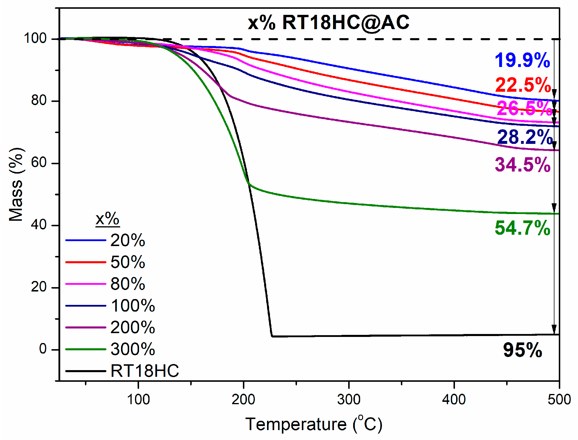
| Sample | Initial Loading (% w.t.) | Weighting Increment (% w.t.) | Mass Loss on TG Curves (% w.t.) | Encapsulation According to TG Curves (% w.t.) |
|---|---|---|---|---|
| 0.2RT18HC@AC | 20 | 28.24 | 19.93 | 24.90 |
| 0.5RT18HC@AC | 50 | 38.50 | 22.48 | 29.00 |
| 0.8RT18HC@AC | 80 | 65.30 | 26.47 | 36.00 |
| 1RT18HC@AC | 100 | 97.63 | 28.24 | 35.80 |
| 2RT18HC@AC | 200 | 114.60 | 34.46 | 52.60 |
| 3RT18HC@AC | 300 | 260.00 | 54.73 | 120.90 |
Disclaimer/Publisher’s Note: The statements, opinions and data contained in all publications are solely those of the individual author(s) and contributor(s) and not of MDPI and/or the editor(s). MDPI and/or the editor(s) disclaim responsibility for any injury to people or property resulting from any ideas, methods, instructions or products referred to in the content. |
© 2024 by the authors. Licensee MDPI, Basel, Switzerland. This article is an open access article distributed under the terms and conditions of the Creative Commons Attribution (CC BY) license (https://creativecommons.org/licenses/by/4.0/).
Share and Cite
Gioti, C.; Vasilopoulos, K.C.; Baikousi, M.; Salmas, C.E.; Ntaflos, A.; Paipetis, A.S.; Viskadourakis, Z.; Ikram, R.; Agathopoulos, S.; Kenanakis, G.; et al. Enhanced Gypsum Boards with Activated Carbon Composites and Phase Change Materials for Advanced Thermal Energy Storage and Electromagnetic Interference Shielding Properties. Micro 2024, 4, 61-79. https://doi.org/10.3390/micro4010005
Gioti C, Vasilopoulos KC, Baikousi M, Salmas CE, Ntaflos A, Paipetis AS, Viskadourakis Z, Ikram R, Agathopoulos S, Kenanakis G, et al. Enhanced Gypsum Boards with Activated Carbon Composites and Phase Change Materials for Advanced Thermal Energy Storage and Electromagnetic Interference Shielding Properties. Micro. 2024; 4(1):61-79. https://doi.org/10.3390/micro4010005
Chicago/Turabian StyleGioti, Christina, Konstantinos C. Vasilopoulos, Maria Baikousi, Constantinos E. Salmas, Angelos Ntaflos, Alkiviadis S. Paipetis, Zacharias Viskadourakis, Rabia Ikram, Simeon Agathopoulos, George Kenanakis, and et al. 2024. "Enhanced Gypsum Boards with Activated Carbon Composites and Phase Change Materials for Advanced Thermal Energy Storage and Electromagnetic Interference Shielding Properties" Micro 4, no. 1: 61-79. https://doi.org/10.3390/micro4010005