1. Introduction
Poly(methylmethacrylate) (PMMA) is a polymer having wide applications in radiation physics. Due to high transparency in the ultraviolet (UV) and visible ranges, PMMA can replace inorganic glasses in optical systems, especially if there is a need to create optics elements of complex shape or large volume. Also, PMMA is used in particle detector elements such as optical fibers, calorimeters, containers, substrates and much more [
1,
2].
Development of nanostructures as quantum dots allows creating scintillators with luminescence duration up to subnanoseconds and required spectrum [
3]. This allows using such structures in high energy physics, dosimetry, etc. In this case, semiconductors [
4] or dielectric [
5] materials can be used as a matrix. One of the frequently used materials for the matrix is PMMA, and it is important to show how this material responds to the charge particle irradiation.
Cherenkov radiation (ChR) is one of the emission mechanisms in PMMA appearing if the speed of a charged particle is higher than the phase light speed in the medium [
6,
7,
8] (
), where
c is the light speed in a vacuum,
n is the refractive index. Since an average value of PMMA refractive index equals to 1.49 [
9], electrons with energy above 178 keV emit ChR.
One more radiation mechanism appearing in PMMA is the scintillation arising due to the transition of electrons between the energy levels in molecules. Authors of the articles [
2,
10] show that even pure PMMA generates optical photons.
We have investigated PMMA samples radiated by the 2.7 electron beam. Such energy allows investigating radiation from absorbed in the PMMA sample beam as well as for a case of the beam energy abates insignificant and to use for it compact radiators.
This paper investigates the influence of ChR and scintillations in the UV and optical ranges of a spectrum for a case of plate PMMA samples, which are generated by the 2.7 MeV electron beam. The article contains three main parts. The experimental setups for PMMA samples irradiation by electron beam is considered in the first part. Simulation results using Monte-Carlo methods for calculating electron beam propagation in PMMA samples of different thicknesses are shown in the second part. The third part is devoted to the investigation of UV and visible photon yield, which is obtained in PMMA targets irradiated by an electron beam.
2. Materials and Methods
We investigated PMMA emission using the experimental setup shown in
Figure 1. The experimental method is similar to described one in the paper [
11] with silica and KBr samples. So, plate PMMA samples with thicknesses of 1 mm and 10 mm have been irradiated with the microtron of Tomsk Polytechnic University [
12] producing the 2.7 MeV electron beam with the duration of 500 ns. The frequency of the beam was equal to 50 Hz. Beam passed through the 50 mcm beryllium foil and stainless steel tube with a diameter of 20 mm. The average current of the beam consisted of ≈
bunches with a duration of 10 ps reached 2.5 mA. The duration of individual electron bunches and the corresponding radiation pulses were less than the time resolution of the registering equipment used in these experiments. The root-mean-square angular deviation of the electron beam after passing through a collimating diaphragm (1) corresponded to
. The collimating diaphragm is the lead tube with an inner diameter of 5 mm, and it was filled by the air. After that, the beam reached the PMMA sample (2), which was fixed on the motorized rotation stage [
13]. The stage could change the angle
between the normal to the PMMA sample and electron beam axis.
Emission was caught by two paths: first of them is to use a converging lens, a fiber, a spectrometer (
Figure 1a); second path showing in the
Figure 1b is the registration with the fiber and a silicon photomultiplier (SiPM). The optical fiber had a length of 1 m and a diameter of 400 mcm and was located under an angle
to the beam axis. The acceptance angle of the fiber is equal to 25.4
. We used
HR2000+ES spectrometer [
14] with a resolution of 0.9 nm and a spectral bandwidth from 190 to 1100 nm. The spectrometer was shielded from the direct hits of electron beam and protected by a lead screen attenuating scattered electrons and X-ray photons. The fiber and the lens were also protected by the lead screen.
The time dependence measurement of optical radiation yield was performed using the SiPM of
MicroFC-SMA-60035 having a time resolution of 3.2 ns and a recovery time of 210 ns. To compare the obtained time distribution with the electron beam current, we used a Faraday cup located just behind the collimating diaphragm. Electrical signals from the Faraday cup and the SiPM was recorded by the GDS-2102 digital oscilloscope (100 MHz, 1 GS/s) [
15].
3. Theory
We will compare experimental spectrum with GEANT4 simulation taking into account only ChR. Scintillations have sufficient narrow spectra comparing with ChR and we can observe discrepancies in the theoretical and experimental spectra caused by scintillations.
The ChR intensity generated by a charged particle at the path of length
L is determined by the Tamm-Frank equation [
6]:
here,
is the photon intensity,
is the fine structure constant,
n is the wavelength-dependent index of refraction. Due to the fact that the electron is losing its energy during its propagation, relative velocity
is decreased and
is become a function
. ChR has a broad spectrum and it is generated if particle velocity exceeds the phase light speed in the medium (
). Model based on Tamm-Frank equation is preprogrammed in the G4Cerenkov class of GEANT4 [
16] and is used by us.
Multiple scattering of the beam electrons is sufficiently influences both the spectra and the angular distribution of the generated optical and UV radiation. The reason is the fact that ChR has main emission direction relative to electron momentum
and radiation angle depends on the module and direction of the electron momentum (
is the ratio of electron velocity
to the speed of light
c). The attenuation of the beam as a function of the PMMA target thickness is shown in the
Figure 2. For obtaining such information, we calculated the energy absorption of 2.7 MeV electron beam using the Monte-Carlo methods in the program GEANT4. We used the class of G4EmStandardPhysics option4 [
17,
18] that allows us to simulate the small energy processes of electron propagation with energy less than 2.7 MeV.
It was supposed that beam with Gauss angular distribution having initial root-mean-square deviation
falls onto the target under a normal angle (
). In this case, PMMA samples with a thickness of
mm absorb half of the beam energy. In order to energy is absorbed completely, the PMMA samples with a thickness of
mm are needed. The root-mean-square deviation of the electron angle regarding its initial moving direction is proportional [
18] to
. Thus, the probability of deviating at large angles increases with increasing sample thickness due to electron energy
E reduces. This fact leads to blurring of the ChR directionality, especially in “thick” samples. Under “thick” samples, we mean PMMA samples with thicknesses in which the beam energy is almost completely absorbed. In contrast, under “thin” samples, we mean PMMA samples which absorb beam energy insignificant.
4. Results
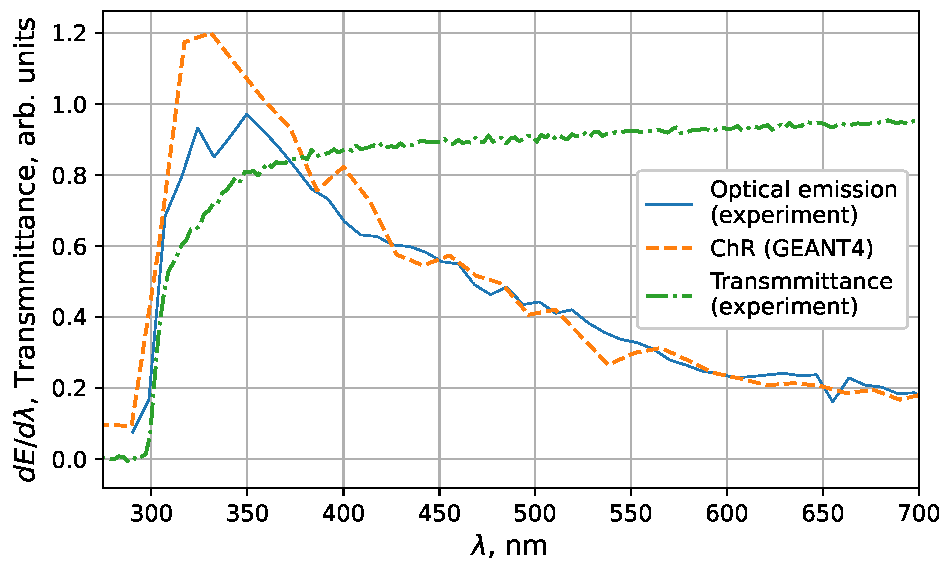
The optical emission obtained by the irradiation of 2.7 MeV electron beam propagating in the 10 mm thick PMMA sample (
Figure 3) coincides with calculated pure ChR for wavelengths longer than 400 nm. The ChR spectrum was normalized in the spectral region where the scintillation yield is small (
nm) [
10] and only ChR influences on the spectra. This relates with the fact, that the maximum of the luminescence spectra for 10 mm PMMA sample is located at 500 nm and has Gauss-like form. Luminescence emission drops to zero at wavelengths close to 350 nm and 700 nm.
We have taken into GEANT4 simulation such medium characteristics as transparency and dispersion dependence of the refractive index
. We measured the spectral transmittance of PMMA samples using the broadband lamp. The model of GEANT4 uses the absorption length of photons instead of transparency. So, the relationship between these values is determined as:
where
T is transmittance. Equation (
2) was obtained from the approximation of exponential photon attenuation.
Presented in database [
9] the dispersion dependence in PMMA provides information about PMMA dispersion for wavelength only longer than 400 nm. Although the articles [
19,
20] describe the methods to refractive index determination in the range less than 400 nm, refractive index values obtained by these methods do not correspond to accepted values for PMMA, which are close to
. So, we used the refractive index from the paper [
21] presented in database [
9] for wavelengths longer than 400 nm, but for shorter wavelengths, we used the refractive index equal to 1.505, which corresponds to
nm.
There is a discrepancy in simulated and experimental results at wavelength range about 300–375 nm (
Figure 3), where influence of luminescence is minimal. We guess, this discrepancy is related to the fact that the refractive index decreases with decreasing wavelength due to the anomalous dispersion. But we do not take this into account and we took refractive index is equal to 1.505 for wavelength range less than 400 nm. Anomalous dispersion arises close to the absorption edge, which strongly affects the spectrum near 300 nm. Despite the existence of a luminescence centers in the optical range and strong absorption in the UV range, the luminescence photons effects weak on the total spectrum.
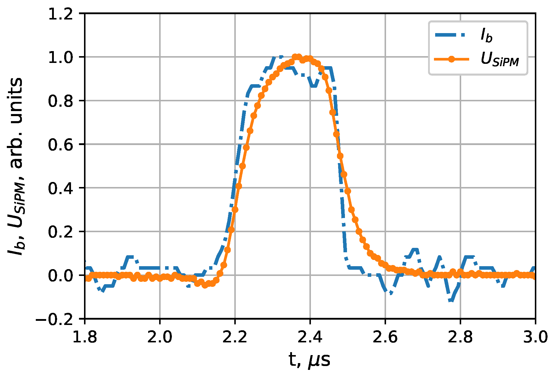
Organic compounds of PMMA have a luminescence decay time of the order of a few nanoseconds [
10,
22,
23], ChR radiates in tens of picoseconds [
7,
22]. Hence, the registered electron beam current is in good agreement with the optical radiation waveform registered by the SiPM, which you can see in
Figure 4. Observed differences in the duration and shape of the beam current and optical radiation in PMMA can be explained by the microcell recovery time of SiPM (210 ns).
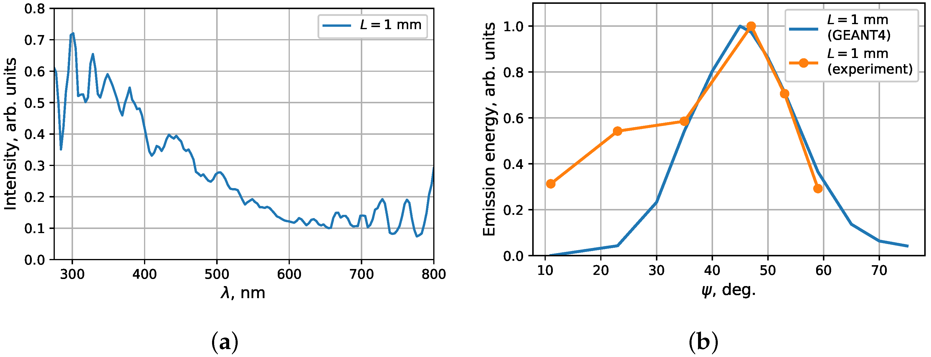
To make sure that we see ChR, we also measured the orientational dependence of the PMMA sample relative to the beam momentum. Electron radiates ChR under angle of
, and scintillations has isotropic angular distribution. We used a “thin” 1 mm PMMA sample (see
Figure 2b) to minimize beam scattering in the PMMA sample. The experimental optical and UV spectra of
Figure 5a corresponds to the ChR spectrum, for which photon energy increases with decreasing wavelength. The orientational dependence of the emission energy in 1 mm PMMA sample on the angle
shows the satisfying coincidence experimental and theoretical curves at angles close to
(
Figure 5b. For smaller angles
, the emission obtained in the experiment exceeds the theoretical calculation. This fact can be related to the roughness of the PMMA sample, which we did not take into account in simulation.
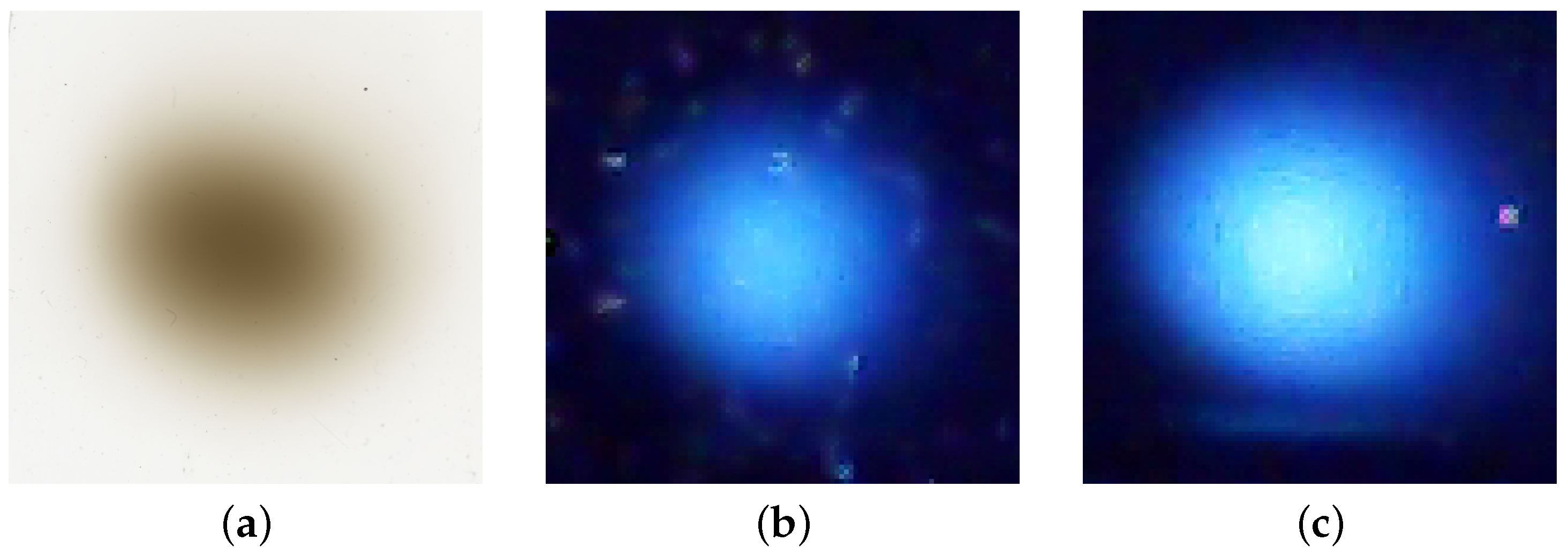
The footprint of the electron beam on the PMMA sample (a) and photographs of the optical radiation of the PMMA samples with thicknesses
(b) and 10 mm (c) are shown in the
Figure 6. Photos were obtained when beam axis was perpendicular to the PMMA sample. Prepotent intensity for the case of the 10 mm PMMA sample compared with 1 mm one in
Figure 6 can be explained by the initial 2.7 electron beam is attenuated just 10 percent of initial energy in 1 mm PMMA sample. A large part of the ChR energy in the visible region is generated in the remaining 9 mm of the PMMA sample.
5. Conclusions
The investigation of PMMA emission excited by an electron beam with an energy of 2.7 MeV shows that ChR makes a main contribution to the optical spectrum. Disagreement in GEANT4 simulated spectra and experimental one can be involved by a mistake in choice of refractive index for wavelengths less than 400 nm. We have taken n is equal to 1.505 but due to the anomalous dispersion the meaning can be significant smaller.
We experimentally obtained, the electron beam current is in good agreement with the optical radiation waveform registered by the SiPM. This means that the main part of the PMMA optical emission is ChR. Also, we have obtained orientational dependence on 1 mm PMMA sample inclination. Angle of maximal emission intensity in good agreement with the calculated one. But at angles less than 35 degrees, experimental data of optical emission energy exceed the calculated values. We assume that this may be caused by the rough surface of the real sample.
The disadvantage of PMMA samples for intense irradiation is their darkening with a radiation dose increase, as well as their destruction due to streamer discharge at a high beam current densities [
10,
23]. The radiation stability of PMMA is significantly lower than that of quartz glass. However, in this experiment, darkening of the PMMA samples was observed, but sample was not destroyed.

 ,
, 


