Article

Rheological and Aesthetical Properties of Polyolefin Composites for Flame Retardant Cables with High Loading of Mineral Fillers

1
Ipool Srl, Spin-Off Company of National Council of Research Institute (CNR), Via Enrico Fermi 75, 51100 Pistoia, Italy
2
Department of Chemistry and Industrial Chemistry, University of Pisa, Via Giuseppe Moruzzi 13, 56124 Pisa, Italy
3
CISUP, Centro per l’Integrazione della Strumentazione dell’Università di Pisa, Lungarno Pacinotti 43, 56126 Pisa, Italy
*
Authors to whom correspondence should be addressed.
Micro 2022, 2(3), 524-540; https://doi.org/10.3390/micro2030034
Submission received: 21 July 2022 / Revised: 23 August 2022 / Accepted: 25 August 2022 / Published: 2 September 2022
(This article belongs to the Special Issue State-of-the-Art Microscale and Nanoscale Researches in Italy)

Abstract

:
It was found that the use of natural magnesium hydroxide (n–MDH) as mineral filler in EVA based composites provided mechanical and rheological properties that did not completely comply with the halogen-free flame-retardant (HFFR) cables parameters. Moreover, the use of n–MDH mostly gave a rough grey surface in the compound extruded by rheometry capillary. In contrast, with the use of synthetic material (s–MDH), a combination of better outcomes was observed. Mechanical and rheological properties were more aligned with the application, and the aesthetics were also improved, i.e., the surface was smooth and whiter. Therefore, with the aim of obtaining good aesthetical quality on the extrudate, we studied formulations by varying the type of polymer matrix and using a mixture of the natural magnesium hydroxide combined with other kind of fillers (in a 3:1 ratio using as main filler n–MDH). On this account, we found a synergistic effect in the mechanical, rheological, and aesthetic properties for the filler blend system containing n–MDH in combination with s–MDH or Böhmite AlO(OH), or using a secondary polymer belonging to the polybutene family combined with EVA.

1. Introduction

Outer sheathing compounds of halogen-free flame-retardant (HFFR) electrical cable require robust mechanical properties, good surface quality, and flame retardancy. These performance attributes are achieved by the incorporation of a high amount of mineral fillers into a polyolefin matrix [1,2]. Our previous work [2] demonstrated that the use of natural magnesium hydroxide Mg(OH)2 (n–MDH, cost-effective and widely available) as filler in a poly(ethylene-co-vinyl acetate) EVA/polyolefin matrix partly complies with the mechanical and flame retardant properties required for cables application due to its irregular particles with wide size distribution and presence of impurities such as carbonates. Higher performances were observed using synthetic magnesium hydroxide Mg(OH)2 (s–MDH) that is characterized by regular particles with hexagonal geometry and narrow size distribution.
Many formulations were studied in the last work [2], which aimed to find the optimal dosage of the selected ingredients and to maximize the mechanical and flame-retardant properties.
The basic formulations, described in Table 1, included the 60 wt.% of the mineral filler, the 3 wt.% of ULDPE-g-MAH as the coupling agent, the 1 wt.% of the processing aid (silicon MB), and the 36 wt.% that consisted of a mixture of the 27 wt.% of poly(ethylene-co-vinyl acetate (EVA) with a content of 28 wt.% of vinyl acetate comonomer and the remaining 9 wt.% of the ethylene α-olefin.
Nevertheless, the major limitation of n–MDH as flame retardant is its use at high concentrations (typically 60–65% by weight, corresponding to approximately 36–42% by volume), which adversely affect some of the properties of the polymer matrix. Attempts to enhance the composite properties were made by changing the polymer matrix and adding n–MDH in combination with other fillers in a 3:1 ratio. Notably, n–MDH combined with Böhmite (AlO(OH)) was found as the most synergic combination for the mechanical and flame retardant characteristics enhancement.
Böhmite, expressed also as Al2O3∙H2O, is a mineral filler obtained by careful control of time and temperature during the process production of alumina trihydrate (ATH, Al(OH)3). It possesses numerous outstanding properties, such as high melting point, low thermal conductivity, high surface area, good chemical stability, low cost, and flame retardancy attributed to the capacity of improving the char formation on the burning materials due to its particle shape [3,4,5]. In the literature, examples are present for the optimization of the filler–matrix interactions to enhance the composite properties [6,7], but only a few of them report on natural fillers [8,9] due to the problematic rationalization of their behaviour within the composite system.
In this study, the same formulations were evaluated regarding the rheological properties and the aesthetical quality of the extrudates prepared using a capillary rheometer. Notably, our aim was to design a new method able to provide reliable indications and predictions on the surface quality of the materials once processed in industrial-scale cable extrusion lines. In this direction, it was decided to test formulations varying in one case the polymer matrix (a blend of an ethylene vinyl acetate copolymer (EVA) and a polymer that can be polyethylene, polypropylene or polybutene) and subsequently the mineral filler.
Notably, the rheology of highly filled composites has a pivotal role since high doping contents are critical in finding the best processing parameters such as temperature, pressure, etc in industrial formulations. High filler contents generally increase shear viscosity over the whole range of shear rates and frequencies [10] and render the rheology of the composites difficult to rationalize since the flow behaviour is also strongly affected by the filler characteristics, such as particle size, morphology, and surface chemistry [11,12]. Therefore, under these conditions, the rheological behaviour of highly filled composites is hardly predicted by the existing theories [13].
The main challenge of this work is to find the optimum trade-off between improvements in the ultimate (mechanical) composite properties provided by fillers and the processing conditions. Specifically, different formulations in terms of both the mineral filler and the polymer composition were selected and tested to obtain the best composite properties that comply with those of the sector regulations and the current production processes. To this aim, the use of a laboratory-scale method based on a capillary rheometer able to study the flow properties at high shear rates and simulate the conditions of large-scale industrial production was introduced.

2. Materials and Methods

The raw materials used for the experiments were:
  • Poly(ethylene-co-vinyl acetate) EVA28, ELVAX 265A, Dow (Dow Europe GmbH, Horgen, Switzerland), containing 28 wt.% of vinyl acetate, Melt Flow Index 190 °C = 3 g/10 min, Density = 0.955 g/cm3.
  • ULDPE-g-MAH, Fusabond N525, Dow (Dow Europe GmbH, Horgen, Switzerland), Ultra Low Density Polyethylene C2-C8 Copolymer, grafted with Maleic Anhydride (0.7–1.1 wt.%), Melt Flow Index 190° C = 3.7 g/10 min, Density = 0.88 g/cm3.
  • Masterbatch of PDMS, Silmaprocess AL1142A by Silma Srl (Prato, Italy), composed by 50 wt.% of high viscosity PMDS and 50 wt.% LLDPE, Silicon MB.
  • Fillers used are described in Table 2:
  • Grades of poly(ethylene-co-α-olefin) used are described in Table 3:
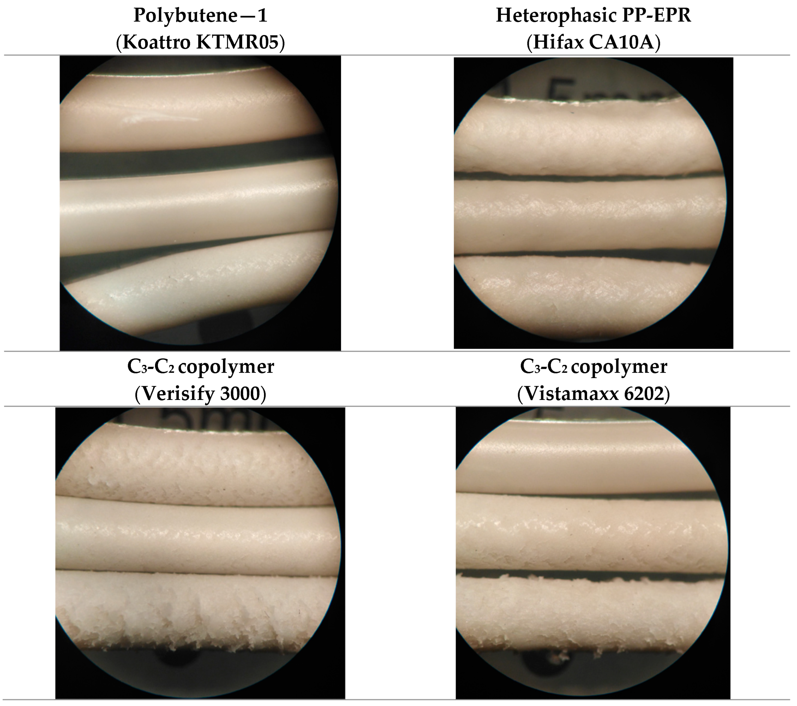
  • Grades of C3-C2 copolymers (propylene-rich) in Table 4:
All the composites were prepared via a twin-roll mixer with rolls of 45 cm × 15 cm at the constant temperature of 140 °C for 10 min. At first, the polymer matrix was melted for 1 min and then the fillers and additives were added as a mixture. After mixing, composites with a thickness of 1.5 mm were recovered.
The flow properties were measured using a Melt Flow Index (MFI) instrument according to the standard ISO 1133:1 and using a capillary rheometer (Gottfert Rheograph 2002) at the constant temperature of 150 °C.
The particle size distribution of the fillers (D50) was evaluated using a laser diffraction method. The analyses were carried out using a Mastersizer 2000 by Malvern Panalytical.
The surface characteristics of the extrudates obtained at different shear rate from the capillary rheometer were observed by using optical microscope (MOTIC B1-220E, Pisa, Italy), and scanning electron microscopy analyses (SEM) were performed to point out morphological properties using a FEI Quanta 450 ESEM FEG.

3. Results

As mineral fillers, natural magnesium hydroxide (n–MDH, Mg(OH)2, Ecopiren 3,5) was compared with the synthetic magnesium hydroxide (s–MDH, Mg(OH)2, Magnifin H5) which was reported to provide significantly higher performances to at the expense of the cost of the formulation [14,15].
Notably, the fillers are characterized by different particles shape and size, due to their production process, i.e., a milling process for n–MDH instead a precipitation process for s–MDH. The n–MDH presents impurities, such as carbonates and irregular needle-like shape particles. Instead, the s–MDH presents hexagonal platy regular particle shapes (Figure 1). The rheological and aesthetical features of the composites filled by the two different fillers were then investigated.

3.1. Capillary Rheometer Analysis

The rheological properties were investigated by means of a capillary rheometer equipped with three kinds of geometry die (Length L—Diameter ∅, in millimetres): 10–1, 10–2 and 30–1, with the aim of developing a laboratory method able to reproduce the extrusion conditions and to have an indication of the surface quality of the extruded material.
Depending on the capillary die, extrudates with different diameters (1 mm and 2 mm) were obtained at various speeds and the rheological properties plotted in Figure 2 and Figure 3 for n–MDH and s–MDH, respectively. In particular, the rheograms show the dependence of apparent shear stress on the apparent shear rate of the different formulations.
Notably, the term “apparent shear rate”, γapp (s−1), defines the shear rate that the melt at the wall would experience at the given volume flow rate if its behaviour were Newtonian (Equation (1)), whereas the “apparent shear stress”, τ (Pa) is defined as the shear stress experienced by the melt in contact with the die wall (Equation (2)).
The velocity with which the piston presses on the material was varied from 2 mm/s (the rightmost point of the curve) to a minimum value of 0.0156 mm/s (the leftmost point). Each point (8 in total) is characterized by a piston speed halved compared to the previous one. All the measurements were conducted at 150 °C to be sure that all the polymer was melted within the chamber.
As shown, the curves obtained with the capillary 10–2, and therefore with double diameter compared to capillaries 10–1 and 30–1, are translated to lower apparent shear rates (γapp), according to the theory (Equation (1)) [16,17]
γ a p p = 4 Q π R 3
Equation (1) Apparent shear rate (s−1)
where:
Q is the flow rate, which is proportional to the speed of the piston pushing the material
R is the die radius
Apparent shear stress (τ), is defined by the Equation (2):
τ = R P 2 L
Equation (2) Apparent shear stress (Pa)
where:
P is the pressure difference and depends on the pressure measured inside the capillary rheometer’s die
R is the die radius
L is the die length
So, with the same capillary geometry, the shear stress is dependent on the pressure measured inside the rheometer die.
An important parameter obtained by using a capillary rheometer is the apparent shear viscosity, η (Pa*s), given by the Equation (3):
η = τ γ a p p
Equation (3) Apparent shear viscosity (Pa*s)
where:
τ is the shear stress
γapp is the shear rate
From both rheograms in Figure 2 and Figure 3 similar trends were observed:
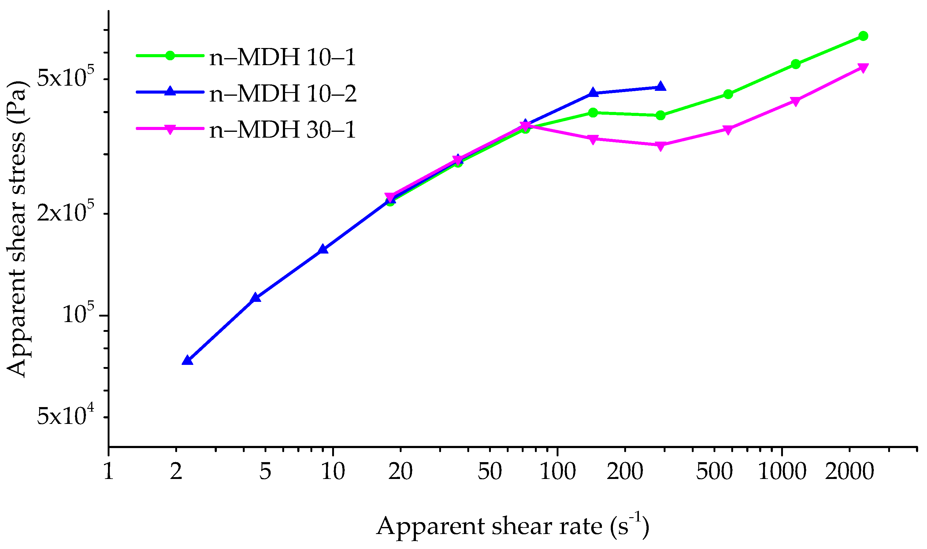
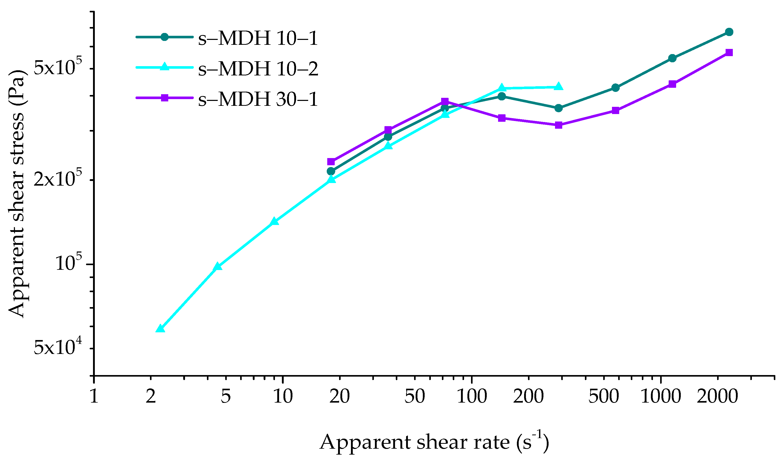
  • In the right part of the rheogram (around 280–2300 s−1), the higher apparent shear rates correspond to the higher apparent shear stress. In this condition Bingham [18] assumed that, during the flow of concentrated suspensions, a “plug flow” system is established and an apparent slip layer is formed. This fact is ascribed to a lack of adhesion between the material and the shearing surface with a thickness that is independent of the flow rate and the nature of the flow mechanism [19]. In this region, the material always comes out smooth thanks to the high pressure that is applied to the surface before the exit from the capillary die. The formation of the apparent slip layer is pivotal for the determination of the rheological parameters, and affects the processing conditions also in terms of the process/product quality control relation. Notably, wall slip reduces the pressurization rate of the single and twin-screw extruders and their mixing capabilities, and the pressure drop in die flows [19].
  • Transition zone (around 150–300 s−1 of apparent shear rate): the phenomenon of sliding overhang (the so-called “slip-stick”) is observed. In particular, during piston lowering there is an increase in pressure until reaching a maximum value. Subsequently, a leakage of the material from the capillary is observed at high speed, thus resulting in a sudden drop of the measured pressure. At this point, the cycle starts again with the decrease of the velocity of exit from the capillary and a new increase of the pressure. Note that under these conditions the measured value of pressure is not accurate, as it follows an oscillatory trend, so the relative value of measured apparent shear stress is to be considered with a greater uncertainty. In this region, the shark-skinned rough extrudate (stick) topology alternates with the smooth glossy extrudate (slip) one. The apparent shear rate increases the intensity of the distortion, which is made less evident by increasing the capillary length [6].
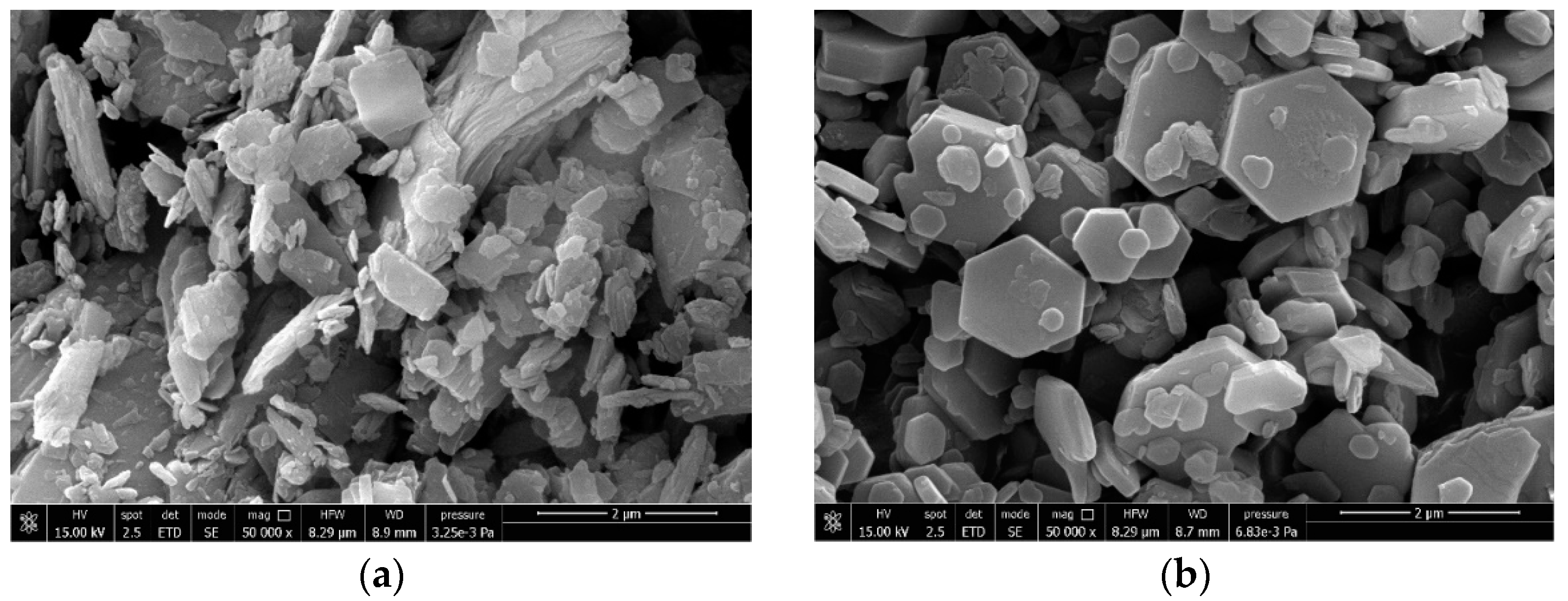
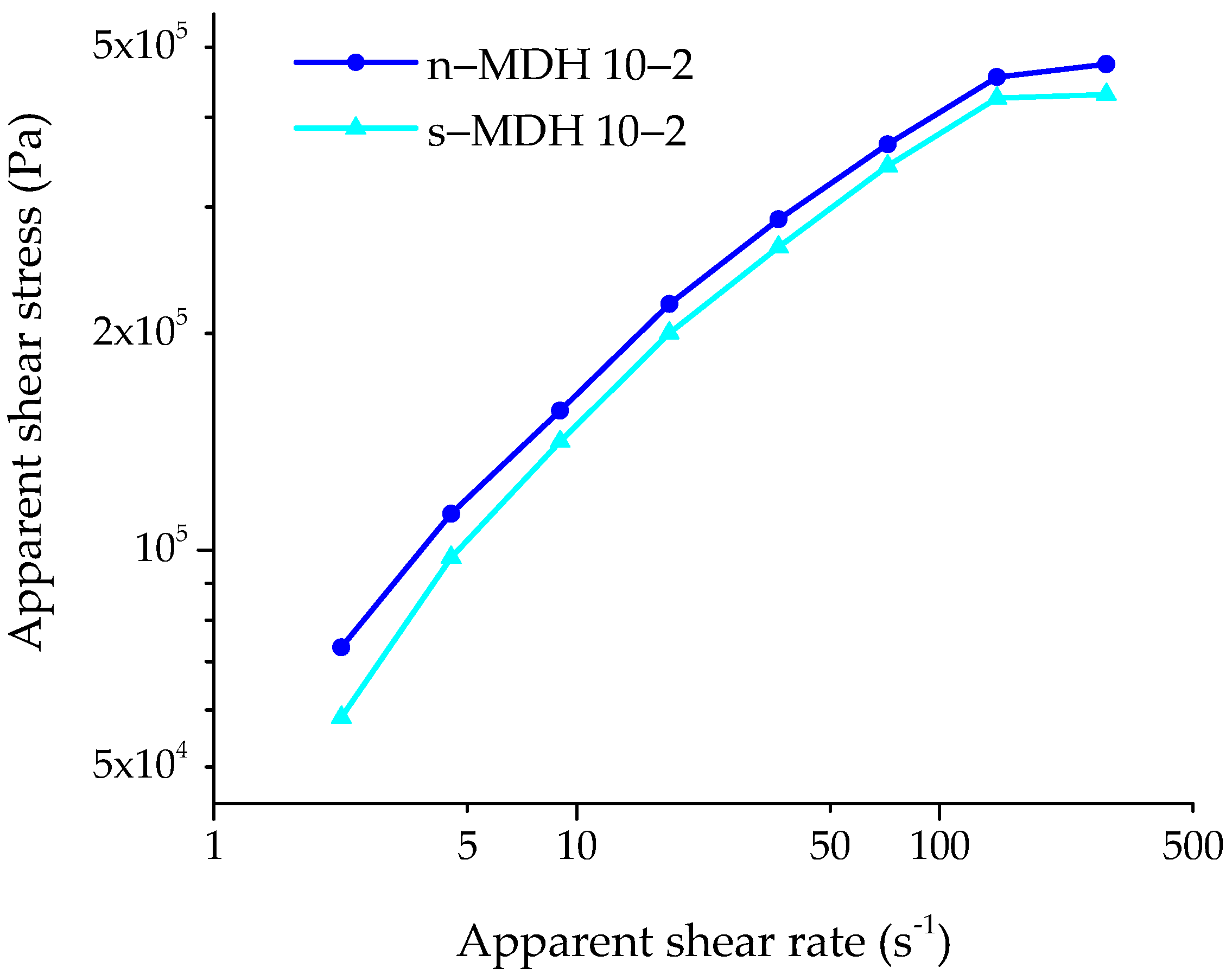
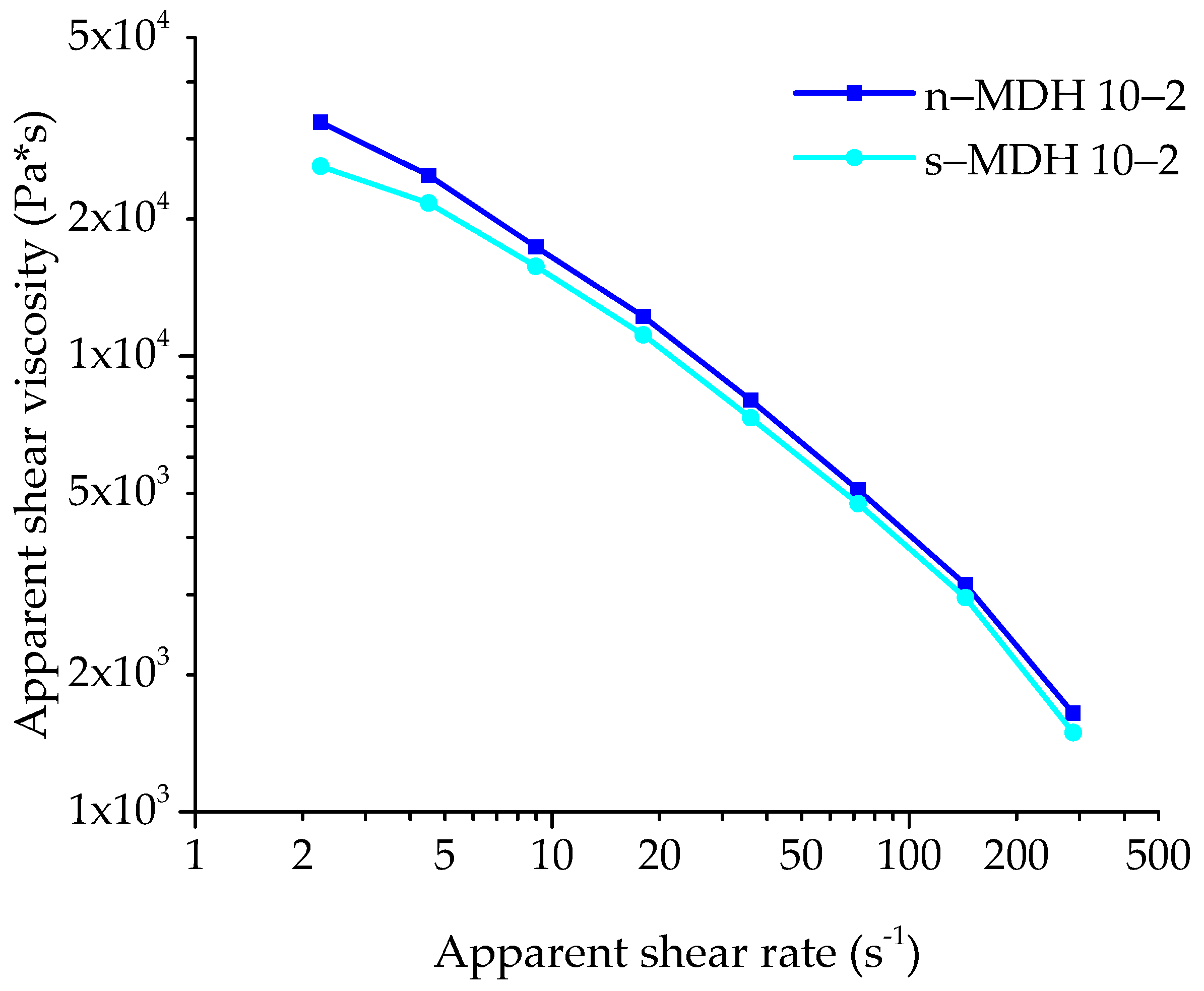
  • In the rheogram of Figure 4, a magnification of the left part of the overlay of the rheograms of n–MDH and s–MDH (2–500 s−1) is reported. Notably, it is possible to notice that there are some differences between the curves obtained using the 10–2 die. This difference could be ascribed to the particle shape as described before: i.e., n–MDH is characterised by an irregular shape (needle-like) that allows the formation of more interactions between the polymer matrix and the filler, thus resulting in a more viscous system (the blue curve is higher than the other one), as also demonstrated by a lower value of MFI observed in literature (9.2 ± 0.5 g/10 min for n–MDH vs. 12.8 ± 0.6 g/10 min for s–MDH) [2].
It is possible to evidence that, since s–MDH particles have a hexagonal platy regular shape, during the capillary measurements, in the melt composite, s–MDH particles should orientate along the flux direction, thus providing a lower obstructing effect of the filler on the plastic flow.
A graph of the apparent viscosity as a function of the apparent shear rate (Figure 5) is presented as well. It is evident that as the shear rate increases, the viscosity decreases, as associated to a shear thinning behaviour typical of pseudoplastic materials [5], as described in the next paragraphs.

3.2. Surface Analysis

After evaluating the mechanical and rheological properties, surface quality of the extrusions obtained from the capillary rheometer was investigated. Flow instability and melt fracture contribute to the formation of surface defect during polymer extrusion, thus enabling the formation of roughness and tearing on the extrudate surface once the material is emerged from the die.
The capillary rheometer allows the analysis of the extrudate morphology can be analysed by capillary rheometry, since different portion of the extrudate can be selected as a function of the shear rate during extrusion. The surface roughness of the extrudates was studied by means of optical and SEM microscopy at the lowest shear rates spanning from 10–20 s−1 to 200–300 s−1, which are typical for cable production [20]. Moreover, under these conditions, the flow and hydrodynamic interaction among composite components are less effective than the intrinsic composite properties.
The surface analysis of the extrudates (n–MDH in Table 5 and s–MDH in Table 6) was first performed on the extrudate obtained from the capillary rheometer using all the capillaries available (10–1, 10–2, and 30–1).
It is possible to observe that at higher shear rate, regardless the geometry of the capillary and the mineral filler (n–MDH or s–MDH), only smooth surfaces were obtained, and corresponding to the plug flow behaviour of the molten compound inside the die. This phenomenon could be explained due to the high pressures, and these could release the material at uniform speeds along the section of the capillary. A polymer film possibly formed on the capillary wall, which favoured the slippage of the melt inside the die, limiting the phenomena of friction as described earlier.
In particular, the incorporation of s–MDH (Magnifin H5) leads to a white, regular, and smooth external morphology at any shear rate, regardless of the geometry of the capillary, confirming that the regularity of the particles shape (hexagonal one, Figure 1b) was also effective on the extrudate surface properties as already reported for mechanical ones [2]. However, the use of this kind of filler makes the compound very expensive, as described in literature [14,15].
From previous studies in our laboratory [5], we know that extruding materials with high n–MDH content presents problems for the surface in addition to producing grey colour composites due to the presence of impurities in the filler resulting from milling process of the brucite [2,15].
As the shear rate decreases it is difficult to clearly classify the n–MDH surface morphology: in this case the pressure involved was much lower and this could cause the presence of inhomogeneous flows responsible for the evident periodic defects causing high surface roughness (sharkskin effect) of the material. This is particularly evident with the use of the capillary die 10–2, confirming those observations from the rheological experiments, where a more evident differentiation is obtained.
SEM analysis (Figure 6) was conducted to evaluate the surface difference among the extrudates with n–MDH at different shear rates.
It is observed that at lower shear rate (Figure 6a), the cohesion between filler and matrix is broken, creating defect points on the surface. Conversely at higher shear rate (Figure 6b), the filler–matrix adhesion is strong enough and the material looks quite homogeneous.
Despite this phenomenon (roughness at lower shear rates) the n–MDH is generally used as flame retardant due to its low cost, its great availability in the world and its natural origin [1].
So, in order to render the surface of n–MDH composite extrudates smoother, the mixing of n–MDH with another filler and the use of a different secondary polymer were taken into account.

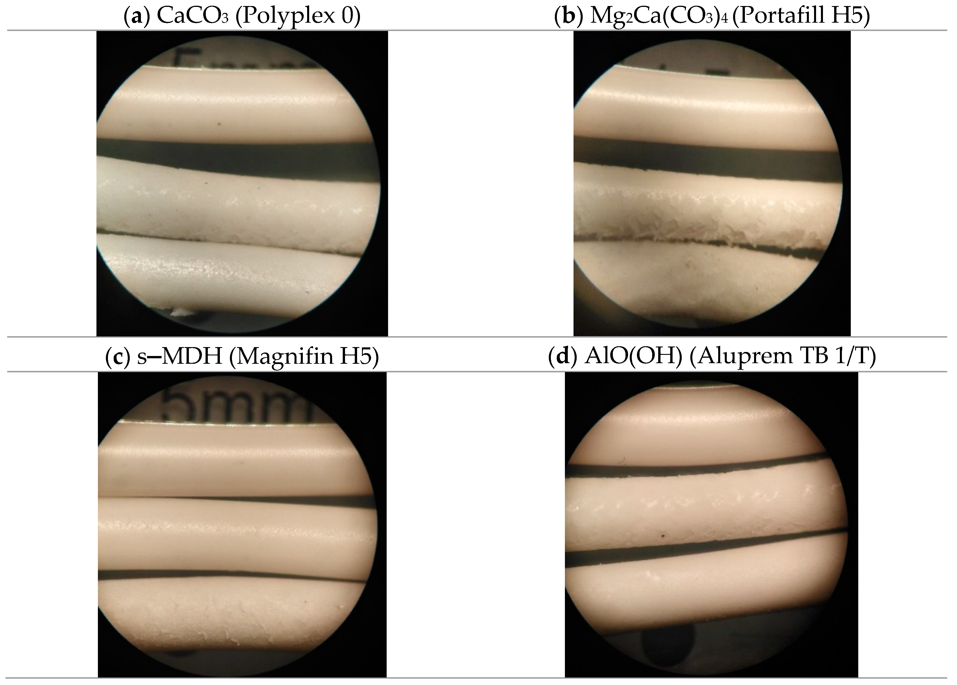
3.3. Variation of Type of Mineral Filler Used in Combination with n–MDH

Natural fillers such as calcium carbonate (CaCO3, Polyplex 0), a mixture of huntite/hydromagnesite (Mg2Ca(CO3)4, Portafill H5), and synthetic fillers, such as Böhmite (AlO(OH), Aluprem TB 1/T), and synthetic magnesium hydroxide (Magnifin H5), were studied.
In particular, CaCO3 (Polyplex 0) presents rounded particles coated with stearic acid while huntite/hydromagnesite (Portafill H5) is characterised by long lamellar with a high BET value of 18 m2/g. Regarding the synthetic fillers, they are characterized by regular shape, i.e., Böhmite (AlO(OH), Aluprem TB 1/T) showing particles almost similar to spheres, while s–MDH (Magnifin H5) presents hexagonal platy shape particles (Figure 7).

3.3.1. Analysis at Capillary Rheometer

The rheological studies shown in Figure 8 were conducted with the capillary die 10–2. Notably, the materials showed viscosity differences at low shear rates, only, and with the typical shear thinning effect at high shear rates. All the composites behave like pseudoplastic materials, i.e., showing viscosity decreasing at higher shearing due to the disentanglement process [21]. Notably, at high shear rates, the presence of filler appears irrelevant for viscosity, since properties are mostly influenced by the hydrodynamic interaction only [21].
In particular, the incorporation of all the types of filler in the polymer matrix (in a 3:1 ratio to n–MDH) causes the increase of the shear stress and the shear viscosity of the materials. Among the curves reported in the graph the presence of natural or synthetic fillers does not lead to evident differences
Therefore, it can be concluded that among all the filler properties, the particle shape seems to be the most influential on the rheological properties of the composites. In fact, differently from fillers with regular shape such as s–MDH, particles characterised by irregular shape such as n–MDH strongly contribute to viscosity enhancement that adversely affects the processability of the filled polymer matrix.
From literature [22,23,24], it is well known that the presence of an organic layer as a surface coating of the particles reduces their tendency to agglomerate, leading to a general reduction in viscosity, as evident from the experiments at lower shear rates for n–MDH combined with stearic acid coated CaCO3 (Polyplex 0).

3.3.2. Surface Analysis

The composites obtained using the natural fillers in combination with the n–MDH were studied in terms of their surface quality. By observing the images embedded in Figure 9, it is possible to see a clear improvement in surface quality compared to the reference compound based only on n–MDH (Ecopiren 3,5) in Table 6.
In particular, calcium carbonate (Polyplex 0) gives a smoother surface than the use of the huntite/hydromagnesite (Portafill H5), possibly due to their different particle size, as described before in Figure 7a,b, respectively. Calcium carbonate presents rounded particles coated with stearic acid that allows an easier dispersion into the polymer matrix generating a good quality of the extrudate surface also at lower shear rate (36 mm/s). Regarding the huntite/hydromagnesite (Portafill H5), the filler is characterised by long lamellar particles that probably agglomerate, thus limiting its wetting by the polymer matrix despite a value of BET of 18 m2/g.
The incorporation of synthetic fillers such as magnesium hydroxide (s–MDH, Magnifin H5) and Böhmite (AlO(OH), Aluprem TB 1/T) leads to regular and smooth external morphology [5], confirming that the regularity of the particle shape of the filler (Figure 7a,d, respectively) is very influential on the extrudate surface properties, as evidenced in Figure 9.
In particular, the mixture of natural magnesium hydroxide (n–MDH) with calcium carbonate (Figure 9a), the mixture of n–MDH with the precipitated one (s–MDH) (Figure 9c), and the mixture of n–MDH with AlO(OH) (Figure 9d) were found to be the best combination of fillers in providing smoothest surface also at very low shear rate (4.5 mm/s) flanked by the lowest viscosity, especially for calcium carbonate as explained earlier. This result is in line also with the mechanical properties obtained in the previous work [2] and is expected particularly for magnesium hydroxide since it gives always smooth surfaces in any extrusion condition [5].

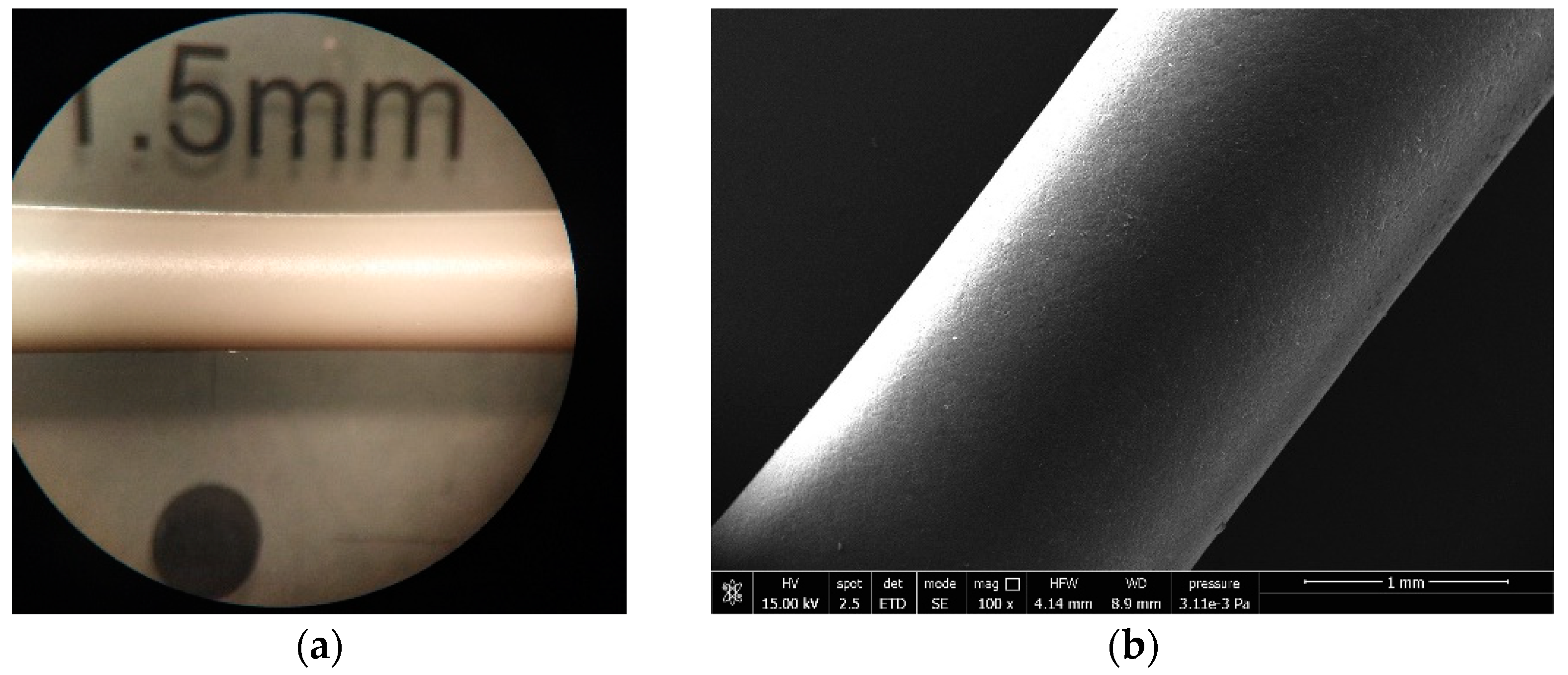
3.4. Variation of Type of Polyoefin Used in Combination with EVA

After evaluating the effect of the filler on the surface quality of the various extrudates, the effect of the secondary polymer was investigated. The filler was kept fixed to 60% of n–MDH and varying the polymer partner of EVA28 to maintain a 3:1 ratio with polymers, such as polyethylene, polypropylene, or polybutene, being common matrices for cable formulations [25].

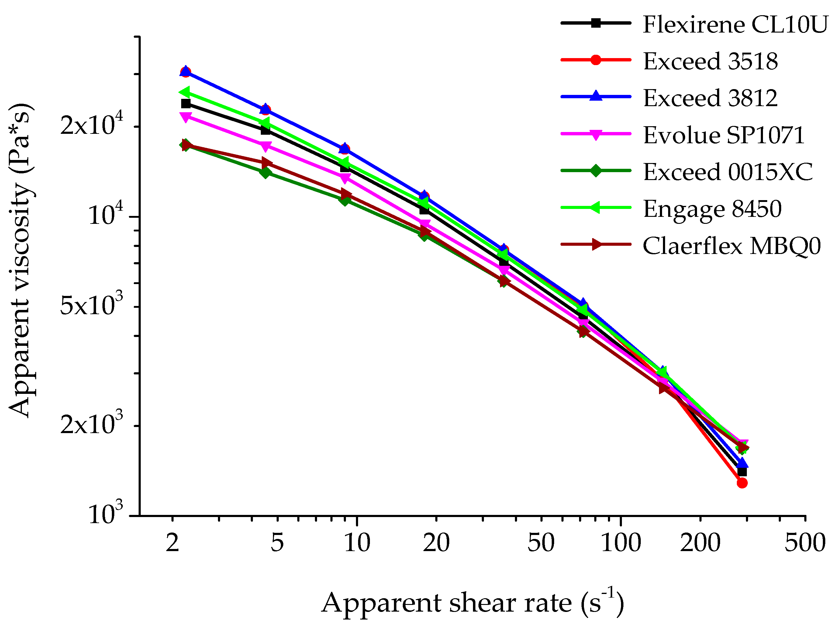
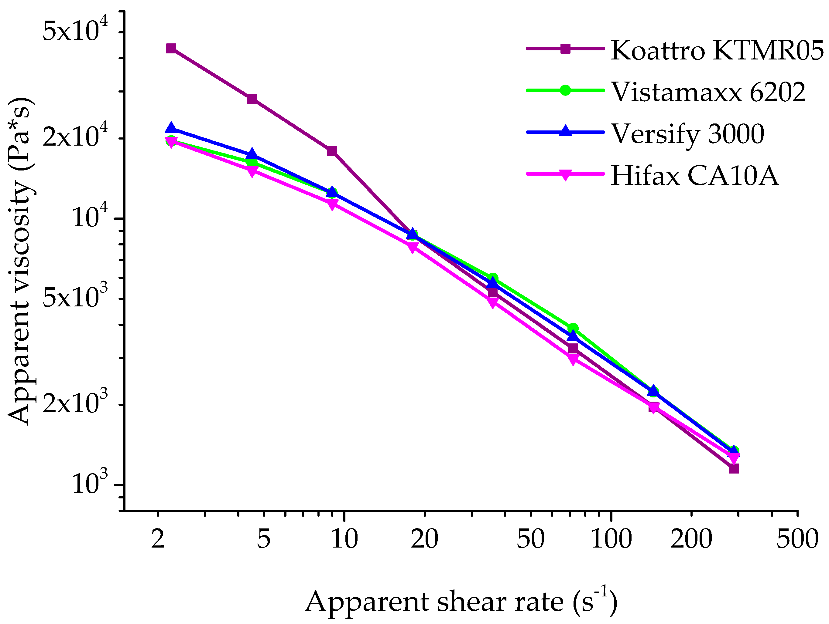
3.4.1. Analysis at Capillary Rheometer

The dependence of viscosity on the shear rate was studied (Figure 10) for the secondary polymer belonging to the polyethylene family and (Figure 11) for polypropylene or polybutene. Again, it can be noted that all the curves show the same trend: the higher difference in viscosity among the materials are more marked at low shear rates (from 2 mm/s to 20 mm/s), while at high shear rates all the systems show nearly the same value and with the typical shear thinning effect.
At low shear rates, it is possible to make a parallelism of the apparent viscosity with the melt flow index value (MFI), since MFI is a rheological measure obtained at low shear values [26]. In particular, it is possible to observe that the composites with the highest viscosity are those with the lowest MFI value [2], both based on a secondary C6-mLLDPE polymer (Exceed 3812 and Exceed 3518 respectively).
The formulation containing polybutene-1 (Koattro KTMR05) as secondary polymer shows a different pattern due to its different compatibility with the polymeric matrix of EVA28 (Figure 11). The poor compatibility of these two polymers with EVA could allow them to behave like external lubricants, thus improving the aesthetic appearance of the composites [27].
As reported earlier, a correlation between the viscosity at low shear rate with the value of MFI can be evidenced: the violet curve (compound based on polybutene-Koattro KTMR05) is characterized by lower MFI value than the other compounds [2].

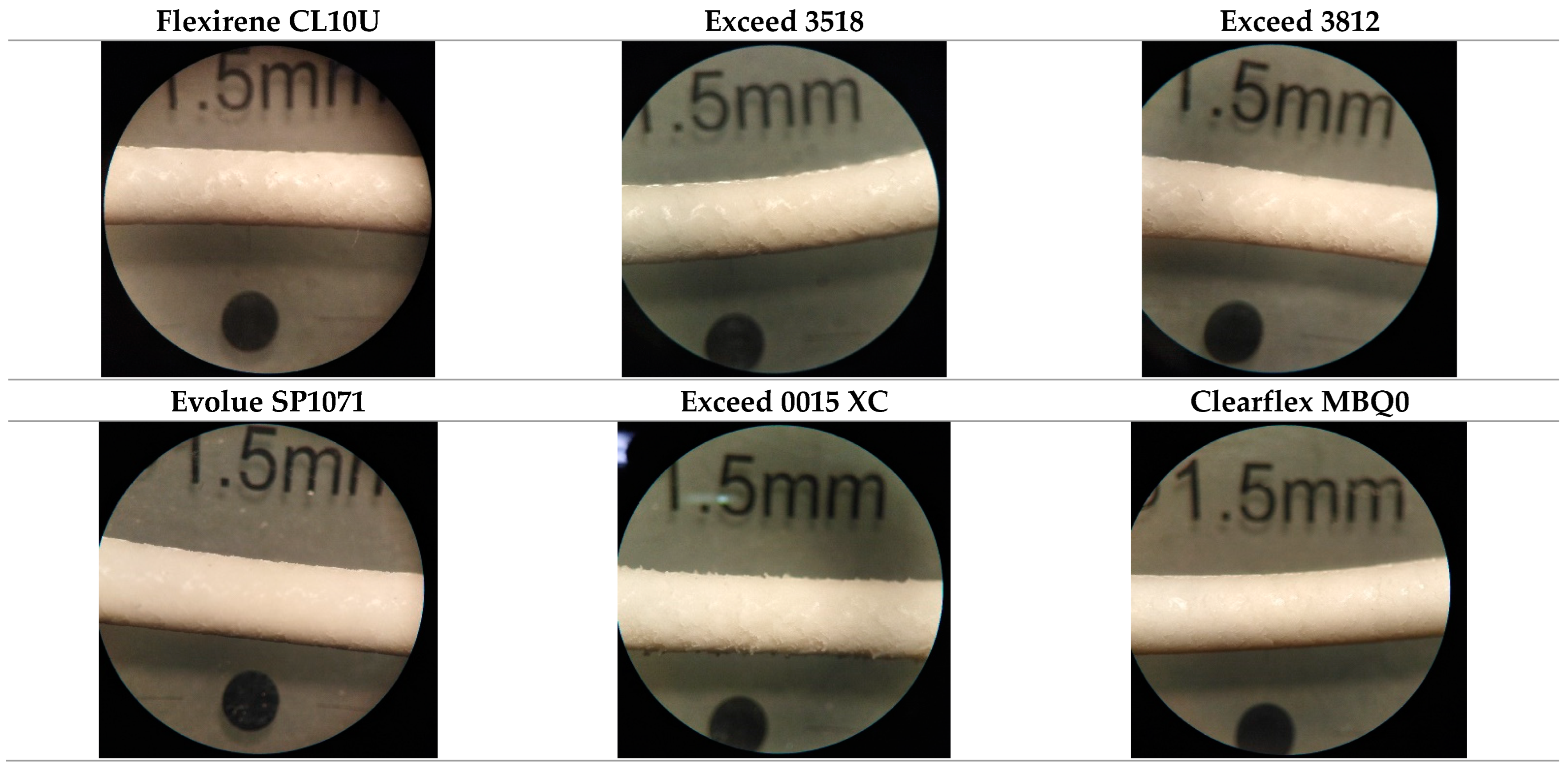
3.4.2. Surface Analysis

The surface quality of the extrudates obtained by varying the secondary polymer was investigated, and a similar behaviour could be found for all the prepared compounds: while the extrudates at higher shear rate show a very smooth and regular surface due to a plug flow effect generated by the high pressure, at lower shear rate the morphology is in general very irregular (Figure 12 and Figure 13). Notably, the use of a polyethylene secondary polymer did not contribute to a smooth surface, despite the fact that Clearflex MBQ0 seemed the best candidate. This behaviour is possibly addressed to the low density of the polymer due to the presence of different content of C4-comonomers (see DSC curve in the Supplementary Materials). The derived branch makes the polymer act as an external lubricant, i.e., going to segregate close to the extrudate, thus conferring smoothness to the composite.
As far as polypropylene or polybutene are concerned as secondary polymers, they are characterized by smoother surfaces also at low shear rate (Figure 14), unlike the compounds made by polyethylene. The reason for this behaviour may be addressed to the low compatibility between EVA and these polymers [27].

4. Conclusions

In this work, several mineral fillers in combination with n–MDH and secondary polymers were tested to investigate their influence on the rheological and aesthetical properties of the final EVA-based composites. The studies showed that using n–MDH as the unique filler gave a rough and grey surface and conferred higher viscosity to the composites. Conversely, s–MDH provided higher performances but the formulation was more expensive. The best synergic combinations were found between n–MDH and natural or synthetic fillers. More specifically, the best results were obtained by using Böhmite, calcium carbonate, or s–MDH, whose regular shape conferred a smoother surface and lower viscosity. Moreover, secondary polymers like polybutene-1 endowed the extrudates with the smoothest surface thanks to the poor compatibility with the main polymer EVA, thus acting as an external lubricant.
Overall, in the present work, an optimized recipe was presented for the formulation of polymer composites with the rheological and aesthetical properties required for electric cable applications. This has been possible thanks to the laboratory-scale method based on a capillary rheometer able to simulate the large scale of extrusion.

Supplementary Materials

The following supporting information can be downloaded at: https://www.mdpi.com/article/10.3390/micro2030034/s1, Figure S1: DSC curves for Clearflex MBQ0.

Author Contributions

Conceptualization, S.H.; formal analysis, S.H. and M.M.; investigation, S.H.; data curation, M.B.; writing—original draft preparation, S.H.; writing—review and editing, A.P.; supervision, A.P.; project administration, C.C. All authors have read and agreed to the published version of the manuscript.

Funding

This research received no external funding.

Institutional Review Board Statement

Not applicable.

Informed Consent Statement

Not applicable.

Data Availability Statement

Data sharing not applicable.

Acknowledgments

CISUP-Centre for Instrumentation Sharing-University of Pisa is kindly acknowledged for SEM measurements. Europiren B.V., Dow Europe, Tor Minerals Europe and Silma S.r.l are kindly acknowledged for supplying the raw materials.

Conflicts of Interest

The authors declare no conflict of interest.

References

  1. Meucci, M.; Haveriku, S.; Badalassi, M.; Cardelli, C.; Ruggeri, G.; Pucci, A. Effect of Polyolefin Elastomers’ Characteristics and Natural Magnesium Hydroxide Content on the Properties of Halogen-Free Flame-Retardant Polyolefin Composites. Micro 2022, 2, 164–182. [Google Scholar] [CrossRef]
  2. Haveriku, S.; Meucci, M.; Badalassi, M.; Cardelli, C.; Ruggeri, G.; Pucci, A. Optimization of the Mechanical Properties of Polyolefin Composites Loaded with Mineral Fillers for Flame Retardant Cables. Micro 2021, 1, 102–119. [Google Scholar] [CrossRef]
  3. Sun, T.; Zhuo, Q.; Chen, Y.; Wu, Z. Synthesis of boehmite and its effect on flame retardancy of epoxy resin. High Perform. Polym. 2015, 27, 100–104. [Google Scholar] [CrossRef]
  4. Li, G.; Liu, Y.; Liu, D.; Liu, L.; Liu, C. Synthesis of flower-like Boehmite (AlOOH) via a simple solvothermal process without surfactant. Mater. Res. Bull. 2010, 45, 1487–1491. [Google Scholar] [CrossRef]
  5. Cardelli, A. Rheological, Mechanical, Thermal and Flame Retardant Properties of EVA Composites Highly Filled with Natural Inorganic Fillers. Ph.D. Thesis, University of Pisa, Pisa, Italy, 2012. [Google Scholar]
  6. Costache, M.C.; Jiang, D.D.; Wilkie, C.A. Thermal degradation of ethylene-vinyl acetate coplymer nanocomposites. Polymer 2005, 46, 6947–6958. [Google Scholar] [CrossRef]
  7. Polansky, R.; Pinkerová, M.; Bartůňková, M.; Prosr, P. Mechanical Behavior and Thermal Stability of EVA Encapsulant Material Used in Photovoltaic Modules. J. Electr. Eng. 2013, 64, 361–365. [Google Scholar] [CrossRef]
  8. Dando, N.R.; Kolek, P.L.; Pearson, A.; Martin, E.S.; Clever, T.R. Aluminum trihydroxide (ATH) as a filler for polymer composites: Comparative evaluation of precipitation and grinding on thermal stability and dehydration kinetics. In Proceedings of the Marketing Technical Sessions of Composites Institutes Annual Conference Composites Institute Society of the Plastic Industry, New York, NY, USA, 5–7 February 1996. [Google Scholar]
  9. Hull, T.; Stec, A. Polymers and Fire. In Fire Retardancy of Polymers: New Strategies and Mechanisms, Proceedings of the 11th Meeting, FRPM’07, Bolton, UK, July 2007; Hull, T.R., Kandola, B.K., Eds.; Royal Society of Chemistry: Cambridge, UK, 2009; p. 433. [Google Scholar]
  10. Malkin, A.Y. Rheology of filled polymers. In Filled Polymers I Science and Technology; Advances in Polymer Science; Enikolopyan, N.S., Ed.; Springer: Berlin/Heidelberg, Germany, 1990; Volume 96. [Google Scholar] [CrossRef]
  11. Bek, M.; Gonzalez-Gutierrez, J.; Kukla, C.; Črešnar, K.P.; Maroh, B.; Perše, L.S. Rheological behaviour of highly filled materials for injection moulding and additive manufacturing: Effect of particle material and loading. Appl. Sci. 2020, 10, 7993. [Google Scholar] [CrossRef]
  12. Mityukov, A.V.; Govorov, V.A.; Malkin, A.Y.; Kulichikhin, V.G. Rheology of highly concentrated suspensions with a bimodal size distribution of solid particles for powder injection molding. Polymers 2021, 13, 2709. [Google Scholar] [CrossRef] [PubMed]
  13. Rueda, M.M.; Auscher, M.C.; Fulchiron, R.; Périé, T.; Martin, G.; Sonntag, P.; Cassagnau, P. Rheology and applications of highly filled polymers: A review of current understanding. Prog. Polym. Sci. 2017, 66, 22–53. [Google Scholar] [CrossRef]
  14. IPOOL. Combination of mineral fillers 3rd phase evolution: Opportunities and drawbacks for the CPR complying cables. In Fire Resistance in Plastic; IPOOL: Cologne, Germany, 2018. [Google Scholar]
  15. Alexander, K. Evolution of natural magnesium hydroxide flame retardants on power and automotive cables. In Past, Present and Future Challenges; Europiren, B.V., Ed.; Cables: Dusseldorf, Germany, 2019. [Google Scholar]
  16. Rahim, N.A.A.; Xian, L.Y.; Munusamy, Y.; Zakaria, Z.; Ramarad, S. Melt behavior of polypropylene-co-ethylene composites filled with dual component of sago and kenaf natural filler. J. Appl. Polym. Sci. 2022, 139, 51621. [Google Scholar] [CrossRef]
  17. Wu, W.; Zeng, K.; Zhao, B.; Duan, F.; Jiang, F. New Considerations on the Determination of the Apparent Shear Viscosity of Polymer Melt with Micro Capillary Dies. Polymers 2021, 13, 4451. [Google Scholar] [CrossRef] [PubMed]
  18. Bingham, E.C. Fluidity and Plasticity; McGraw-Hill: New York, NY, USA, 1922; Volume 2. [Google Scholar]
  19. Kalyon, D.M. Apparent slip and viscoplasticity of concentrated suspensions. J. Rheol. 2005, 49, 621–640. [Google Scholar] [CrossRef]
  20. Gahleitner, M. Melt rheology of polyole®ns. Prog. Polym. Sci. 2001, 26, 895–944. [Google Scholar] [CrossRef]
  21. Samsudin, M.S.F.; Ishak, Z.A.M.; Jikan, S.S.; Ariff, Z.M.; Ariffin, A. Effect of filler treatments on rheological behavior of calcium carbonate and talc-filled polypropylene hybrid composites. J. Appl. Polym. Sci. 2006, 102, 5421–5426. [Google Scholar] [CrossRef]
  22. Osman, M.A.; Atallah, A. Interparticle and particle–matrix interactions in polyethylene reinforcement and viscoelasticity. Polymer 2005, 46, 9476–9488. [Google Scholar] [CrossRef]
  23. Kaully, T.; Siegmann, A.; Shacham, D. Rheology of highly filled natural CaCO3 composites: IV. Effect of surface treatment. Polym. Adv. Technol. 2007, 18, 696–704. [Google Scholar] [CrossRef]
  24. Hornsby, P.R.; Mthupha, A. Rheological characterization of polypropylene filled with magnesium hydroxide. J. Mater. Sci. 1994, 29, 5293–5301. [Google Scholar] [CrossRef]
  25. Polymers For Use in Wire and Cable Compounds. 2019. Available online: https://www.entecpolymers.com/resources/news/polymers-for-use-in-wire-and-cable-compounds#:~:text=THESEPOLYMERSINCLUDE%3A&text=EthyleneAcrylateCopolymers(Methyl%2CEthyl,-1(PB-1) (accessed on 12 July 2021).
  26. Lapasin, R. Reologia Dei Polimeri Fusi; University of Trieste: Trieste, Italy, 2008; pp. 1–16. [Google Scholar]
  27. Available online: http://plasticnotes.blogspot.com/2009/11/pb-1.html (accessed on 10 July 2020).
Figure 1. SEM micrographs of n–MDH (a) and s–MDH (b) (scale bar 2 μm).
Micro 02 00034 g001
Figure 2. Flow curves for the composites containing n–MDH at different size die at 150 °C.
Micro 02 00034 g002
Figure 3. Flow curves for the composites containing s–MDH at different size die at 150 °C.
Micro 02 00034 g003
Figure 4. Flow curves for the composite containing n–MDH (blue curve) and s–MDH (cyan curve) at size die equal to 10–2 at 150 °C.
Micro 02 00034 g004
Figure 5. Apparent viscosity as a function of the apparent shear rate for the composites containing n–MDH (blue curve) and s–MDH (light blue curve) at size die equal to 10–2 at 150 °C.
Micro 02 00034 g005
Figure 6. SEM micrographs of the compound containing n–MDH at different shear rate: (a) 36 mm/s (b) 144 mm/s (scale bar 300 μm).
Micro 02 00034 g006
Figure 7. SEM of the natural/synthetic fillers (scale bar 1 or 2 μm) (a) CaCO3 (Polyplex 0), (b) Mg2Ca(CO3)4 (Portafill H5), (c) s–MDH (Magnifin H5), (d) AlO(OH) (Aluprem TB 1/T).
Micro 02 00034 g007
Figure 8. Apparent viscosity as a function of the apparent shear rate for the composite with different fillers combined with n–MDH in a 3:1 ratio at 150 °C with a size die equal to 10–2.
Micro 02 00034 g008
Figure 9. Extrudates of the composites with a diameter of 2 mm in descending order of shear rate (144 mm/s, 36 mm/s and 4.5 mm/s). Formulation is: 27 wt.% EVA28, 9 wt.% Engage 8450, 3 wt.% ULDPE-g-MAH, 60 wt.% n–MDH in combination with a secondary filler (3:1 ratio), 1 wt.% Silicon MB.
Micro 02 00034 g009
Figure 10. Flow curves at 150 °C for the composites based on ethylene-α-olefin copolymers in combination with EVA.
Micro 02 00034 g010
Figure 11. Flow curves at 150 °C for the composites containing C3-copolymers and C4-copolymer in combination with EVA.
Micro 02 00034 g011
Figure 12. Extrudates obtained by varying the secondary polymer at shear rate of 36 mm/s. Formulation is: 27 wt.% EVA28, 9 wt.% with a secondary polymer polyethylene based, 3 wt.% ULDPE-g-MAH, 60 wt.% n–MDH, 1 wt.% Silicon MB.
Micro 02 00034 g012
Figure 13. Extrudates obtained by varying the secondary polymer at different shear rate (144 mm/s, 36 mm/s and 4,5 mm/s). Formulation is: 27 wt.% EVA28, 9 wt.% with a secondary polymer polypropylene or polybutene based, 3 wt.% ULDPE-g-MAH, 60 wt.% n–MDH, 1 wt.% Silicon MB.
Micro 02 00034 g013
Figure 14. Extrudates obtained by using Koattro KTMR05 as secondary polymer at 4.5 mm/s shear rate (a) optical and (b) SEM micrographs.
Micro 02 00034 g014
Table 1. Basic formulation.
Ingredients% in WeightFunction
EVA 28-327Flexibility, polarity, good behaviour in fire tests (char forming)
Ethylene α-olefin copolymer9Modifier of rheology and surface quality
Mineral filler 60Flame retardant
ULDPE-g-MAH3Coupling agent
Silicon MB1Processing aid
Table 2. Type of Fillers used in this work.
IngredientChemical FormulaOriginTrade nameSupplierD50 *1
(μm)
BET *2
(m2/g)
n–MDHMg(OH)2NaturalEcopiren 3,5Europiren
(Rotterdam, Netherlands)
3.4311–13
CaCO3
stearic coated
CaCO3NaturalPolyplex 0Calcit
(Stahovica, Slovenia)
2.109.5
BöhmiteAlO(OH)SyntheticAluprem TB 1/TTor Minerals
(Hattem, Netherlands)
1.2112
s–MDHMg(OH)2SyntheticMagnifin H5Huber
(Bergheim, Germany)
1.504–6
HuntiteCaMg3(CO3)4NaturalPortafill H5Sibelco
(Maastricht, Netherlands)
3.2718
*1 D50: The portions of particles with diameters smaller and larger than this value are 50%. Also known as the median diameter. Measured by laser diffraction method according to ISO 13320. *2 BET: Determination of the overall specific external and internal surface area of disperse or porous solids measuring the amount of physically adsorbed gas (N2) according to ISO 9277. From TDS.
Table 3. Grades of Poly(ethylene-co-α-olefin) used in this work.
Ingredient *3Trade NameSupplierDensity *1MFI *2Catalysis
C4-LLDPEFlexirene CL10UVersalis
(Mantova, Italy)
0.9182.5Z-N
C6-mLLDPEExceed 3518ExxonMobil
(Machelen, Belgium)
0.9183.5metallocene
C6-mLLDPEExceed 3812ExxonMobil
(Machelen, Belgium)
0.9123.8metallocene
C6-mLLDPEEvolue SP1071CPrime Polymer
(Tembusu, Singapore)
0.91010metallocene
C6-mLLDPEExceed 0015XCExxonMobil
(Machelen, Belgium)
0.91815metallocene
C8-ULDPEEngage 8450Dow
(Horgen, Switzerland)
0.9023metallocene
C4-VLDPEClearflex MBQ0Versalis
(Mantova, Italy)
0.91113Z-N
*1 ASTM D792/ASTM D1505 (g/cm3). *2 MFI (2.16 kg@190 °C) ASTM D1238/ISO 1133 (g/10 min). *3 C4-VLDPE = Very Low Density Polyethylene (comonomer butene), C4-LLDPE = Low Linear Density Polyethylene (comonomer butene), C8-ULDPE = Ultra Low Density Polyethylene (comonomer octene), C6-mLLDPE = metallocenic Linear Low Density Polyethylene (comonomer 1-hexene).
Table 4. Grades of C3-C2 copolymers used in this work.
IngredientTrade NameSupplierDensity *1MFI *2Catalysis
Heterophasic PP-EPRHifax
CA10A
Lyndell-Basell
(Ferrara, Italy)
0.8800.6Z-N
C3-C2 copolymerVistamaxx 6202Exxon-Mobil
(Machelen, Belgium)
0.8629.1metallocene
C3-C2 copolymerVersify
3000
Dow
(Horgen, Switzerland)
0.8918metallocene
*1 ASTM D792/ASTM D1505. *2 MFI (2.16 kg@190 °C) ASTM D1238/ISO 1133.
Table 5. Surface analysis of the extrudates at various size die at different shear rate of the piston for n–MDH composite.
n–MDH (Ecopiren 3,5)
Capillary
Die
High Shear
(2 mm/s)
Low Shear
(0.0156 mm/s)
10–1
L = 10 mm
∅ = 1 mm
Micro 02 00034 i001 Micro 02 00034 i002
10–2
L = 10 mm
∅ = 2 mm
Micro 02 00034 i003 Micro 02 00034 i004
30–1
L = 30 mm
∅ = 1 mm
Micro 02 00034 i005 Micro 02 00034 i006
Table 6. Surface analysis of the extrudates at various size die at different shear rate of the piston for s–MDH composite.
s–MDH (Magnifin H5)
Capillary
Die
High Shear
(2 mm/s)
Low Shear
(0.0156 mm/s)
10–1
L = 10 mm
∅ = 1 mm
Micro 02 00034 i007 Micro 02 00034 i008
10–2
L = 10 mm
∅ = 2 mm
Micro 02 00034 i009 Micro 02 00034 i010
30–1
L = 30 mm
∅ = 1 mm
Micro 02 00034 i011 Micro 02 00034 i012
Publisher’s Note: MDPI stays neutral with regard to jurisdictional claims in published maps and institutional affiliations.

