All articles published by MDPI are made immediately available worldwide under an open access license. No special
permission is required to reuse all or part of the article published by MDPI, including figures and tables. For
articles published under an open access Creative Common CC BY license, any part of the article may be reused without
permission provided that the original article is clearly cited. For more information, please refer to
https://www.mdpi.com/openaccess.
Feature papers represent the most advanced research with significant potential for high impact in the field. A Feature
Paper should be a substantial original Article that involves several techniques or approaches, provides an outlook for
future research directions and describes possible research applications.
Feature papers are submitted upon individual invitation or recommendation by the scientific editors and must receive
positive feedback from the reviewers.
Editor’s Choice articles are based on recommendations by the scientific editors of MDPI journals from around the world.
Editors select a small number of articles recently published in the journal that they believe will be particularly
interesting to readers, or important in the respective research area. The aim is to provide a snapshot of some of the
most exciting work published in the various research areas of the journal.
This paper offers a novel view for managing and controlling the movement of driverless, i.e., autonomous, vehicles by converting this movement to a simulated train movement moving on a rail track. It expands on the “virtual track” theory and creates a model for virtual track autonomous vehicle management and control based on the ideas and methods of railway train operation. The developed model and adopted algorithm allow for large-scale autonomous driving vehicle control on the highway while considering the temporal-spatial distribution of vehicles, temporal-spatial trajectory diagram optimization, and the management and control model and algorithm for autonomous vehicles, as design goals. The ultimate objective is to increase the safety of the road traffic environment when autonomous vehicles are operating in it together with human-driven vehicles and achieve more integrated and precise organization and scheduling of these vehicles in such mixed traffic conditions. The developed model adopted a “particle swarm” optimization algorithm that is tested in a hypothetical network pending a full-scale test on a real highway. The paper concludes that the proposed management and control model and algorithm based on the “virtual track” theory is promising and demonstrates feasibility and effectiveness for further development and future application.
With the advent of autonomous driving and its interaction with connected intelligent transportation systems, the promotion of an “intelligent” road vehicle network with an efficient management and control strategy for autonomous vehicles has become an essential part of autonomous mobility research. Higher requirements and challenges are put forward for future autonomous transportation infrastructures, the autonomous vehicle management and control systems, the vehicle-infrastructure cooperated autonomous driving (VICAD) services, and safety rules. The existing autonomous driving technologies are mainly focused on single vehicle intelligence and tend to ignore the wider network-related problems and challenges related to the overall movement of autonomous vehicles on the network, i.e., the macro-level. There are still problems and issues associated with autonomous driving when dealing with these challenges. Basically, there are two main areas of consideration:
The safety and stability of autonomous vehicles as seen at the micro-level, i.e., the processing of the individual vehicle movement in the road network, and
The safety and stability of the traffic stream at the macro-level, which includes the movement of the autonomous vehicles in the traffic stream together with other human-driven vehicles.
The research reported in this paper focuses on both these areas, but primarily on the second, as it considers the movement and control of autonomous vehicles within a full network at mixed traffic conditions. It is doing so by presenting a novel methodology for converting the autonomous road vehicle movement to a railway-like system in which the road travel scene of autonomous vehicles is transformed into a railway travel scene. In this way, conditions are created for the application of railway train operation and control ideas onto the autonomous road transport operation. In doing so, the proposed “virtual track” theory application is based on simulating the movement of a batch of autonomous vehicles on the road network to the movement of a train on the rail network, and then applying train management and control strategies and algorithms. This idea can be a game changer since autonomous vehicles do use an extensive array of various sensors, network controllers, cloud-based services and resource databases, etc., that make their movement subject to—or particularly suited—to a “guided” way of operation, similar to that of railway vehicles. Data perception, data transmission, and independent decision-making are the main characteristics of smart rail vehicles that can eliminate security risks at the vehicle end. New technologies and business models, such as the use of artificial intelligence, big data, cloud computing, and the features of the open Internet can better be applied to a concept that resembles rail vehicle movement, i.e., movement following a track, rather than that of a free moving road autonomous vehicle.
The strengthening of the safety and stability of the operation of autonomous vehicles, and the lessening of the risks involved in the operation of autonomous road vehicles by simulating their movement to match that of a rail vehicle is strengthened by the following further considerations. The inner software of a road autonomous vehicle has a congenital safety hazard itself in that, at the beginning of its design, the vehicle’s safety decisions vis a vis the hazards it can face cannot be manifested clearly, and they cannot be compared to those perceived by an independent driving individual at present. These decision rules will be improved with the continuous deepening of vehicle intelligence, networking, and the interaction with external data. All this, together with the tendency of vehicles to become more intelligent and more connected, will make automobiles increasingly complex and more computer-like with software codes that exceed hundreds of millions of lines and a great number of sensors and Electronic Control Units (ECUs). The issues of successfully resolving the safety hazards of the vehicle under a large number of situations (application scenarios) will become increasingly prominent and, at the end, may perhaps be the main concern of autonomous vehicles manufacturers. The emergence of certain specific scenarios will always cause a potentially fatal safety hazard for the operation of autonomous vehicles, and this danger is reduced when equating the movement of road autonomous vehicles with that of trains moving on a rail track.
Existing autonomous driving technologies primarily focus on the individual vehicles and the use of advanced sensors (radar, camera), controllers, actuators, and vehicle-mounted sensing systems and information terminals to convert them to autonomous driving. These technologies will need to be complemented with network-wide applications of intelligent information exchange between the users (people), the vehicles, the roads, and the control centers to further enable autonomous vehicles to move safely within the traffic stream and acquire intelligent environmental perception and other capabilities. The ultimate goal is to make them able to face the many dangerous situations and states that can arise in a free and unchecked by a human driver movement in accordance with the user’s wishes. The method of autonomous traffic control at the macro-level proposed in this paper addresses the above considerations and enables full and effective control of their movement by virtually converting the autonomous road vehicle movement to an equivalent movement of a railway convoy of vehicles (train). So, the research questions to which this paper will attempt to answer, are:
Can we transform the autonomous road vehicles’ operation into a railway-like one?
Is the “virtual track” theory and its related mathematics a practical tool for converting road autonomous vehicles to a train-like process?
How can we optimize and control the movement of the “virtual track” autonomous vehicles?
How feasible and practical is such a transformation?
1.1. Literature Review
The focus of this paper is the macro-scale management and control of autonomous vehicles circulating in the traffic stream together with other human-driven vehicles. The basic concept is to replicate (simulate) the movement of autonomous vehicles with that of railway wagon formations, and then apply railway train operation control techniques to guide highway autonomous driving. The literature review therefore involves a wide range of fields which have been grouped in four categories starting with the initial basic vehicle routing problems, then moving on to the more recent work on vehicle formation, traffic control, dynamic traffic allocation simulation, and finally, to the vehicle following theories and vehicle trajectory optimization models. At the end, the relevant literature about the theory and methods of rail transport and train operation control, which are the most relevant issues to the virtual track theory application used in this paper, are reviewed.
1.1.1. Vehicle Routing, Path Planning and Dispatching
The Vehicle Routing Problem (VRP) is a classic network flow problem. It refers to the selection of a set of routes that satisfy the demand for movement between an origin (O) and a destination (D). The original research dates to about 40 years ago, and it was initiated by trying to solve vehicle path problems for the distribution of goods in urban areas. It was enhanced later with the need to observe time windows. Dumas et al. [1] were among the first to put forward a precise algorithm for the routing of multiple vehicles with multiple destinations (distribution points–warehouses, etc.). This algorithm was based on the shortest path but with road capacity, time window, priority and coupling constraints. Psaraftis et al. [2] proposed a dynamic planning solution for a single vehicle, then developed an algorithm that solved this problem using polynomial time algorithms by using the O-value (n23n). Ropke et al. [3,4] proposed a different approach using “branches” and a pricing algorithm in which the basic, non-basic and shortest paths were regarded as pricing sub-problems in the generation algorithm. Savelsbergh et al. [5], Baldacci et al. [6], and Visentin et al. [7] made comprehensive reviews and proposed algorithmic solutions to solve the multiple vehicles, multiple destinations, and the rescheduling problems, as well as the vehicle formation operation which is examined in the following section.
1.1.2. Vehicle Formation, Traffic Control and Dynamic Traffic Allocation
The vehicle formation problem, which refers to forming a linear group composed of several vehicles running on the road along the same path with a small distance between them, has the closest proximity to the research focus of this paper. Through vehicle formation control, road traffic capacity and vehicle density can be effectively improved, and road capacity increased. Alvarez and Horowitz [8] developed an early prototype for vehicle formation in highways. For single lane scenes, their research has designed a safe area for the two-vehicle formation based on the distance, relative speed, and maximum acceleration and deceleration rates. Horowitz and Varaiya [9] described the design of the “automatic highway” system (AHS) that was developed in the PATH (California Partners for Advanced Transportation Technology of UC Berkeley) research center and evaluated related vehicle formation methods in both the simulation and physical testing environments. Lioris et al. [10] verified a fleet of connected vehicles can double the capacity of urban roads by analyzing three queuing models and other simulation research on road networks, with a total of 16 intersections and 73 sections. They found that vehicle convoys composed of platooned vehicles can double the urban road traffic capacity. Several advanced adaptive traffic signal control systems have been developed in the last three decades within the scope of network traffic control. They use dynamic programming and predictive optimization methods to solve platooning traffic control issues, including commercial vehicle platoon systems. Quite typical of these are the SCOOT system developed by Hunt et al. [11], the SCATS developed by Lowrie et al. [12], the OPAC by Gartner et al. [13,14], the RHODES system by Mirchandani et al. [15,16], and the PAMSCOD system by He et al. [17]. The Rhodes traffic control system can use dynamic programming and predictive optimization methods in the optimal control framework based on “rolling fields”, while the PAMSCOD considers vehicle formation arrivals when setting a traffic signal. Other notable developments from the same period were the ALINEA system developed by Papageorgiou et al. [18] and the MILOS system developed by Gettman et al. [19]. Zhou et al. [20] unveiled the effect of maximum CAV platoon size in terms of road capacity and traffic flow stability by developing the analytical formulations of the capacity and flow stability. Ma et al. [21] addressed the robust optimal control problem for connected and automated vehicle platoons that are subject simultaneously to uncertain parasitic actuation lag and input delays by formulating robust optimal control problem as a min–max optimization problem. Shen et al. [22] developed distributed optimization-based, platoon-centered connected and autonomous vehicle (CAV) car-following schemes under the linear vehicle dynamics via the model predictive control approach with a general prediction horizon. Wang et al. [23] proposed a robust cooperative control (RCC) strategy which is developed as a min–max problem to ensure the safe and efficient maneuvering of a CAV platoon in the worst-case situation due to uncertainties in the vehicle dynamics. Zhang et al. [24] developed a platoon-based cooperative lane-change control (PB-CLC) using a hybrid model predictive control (MPC) system.
The use of dynamic traffic allocation (DTA) models and simulation of user equilibriums and optimization through minimization of traffic congestion costs, is another group of relevant DTA models. They are used to predict the time-varying traffic flow due to road capacity constraints and the resulting spatio-temporal congestion changes. The DTA models use traffic flow theory to spread traffic flow within discrete time periods. This category includes the VISTA model developed by Ziliaskopoulos et al. [25], the DYNASMART by Mahmassani et al. [26], the DYNAMIT by Ben-Akiva et al. [27], and the DTALITE model developed by Zhou et al. [28]. Ziliaskopoulos et al. [29], Gao et al. [30], and Unnikrishnan et al. [31] have adopted the user equilibrium model with system optimization to evaluate and design traffic management measures. At the same time, Lin et al. [32] and Peeta [33] have studied system optimization by using marginal costs to minimize traffic congestion costs.
1.1.3. Vehicle following Models
Vehicle following (VF) behavior is the vehicle driving behavior mostly studied in the literature. It describes the interaction between two adjacent vehicles in a convoy on a one-way road where overtaking is restricted. The vehicle following model uses dynamic methods to study the corresponding behavior of the following vehicle caused by changes in the motion behavior and state of the leading vehicle. The traffic flow characteristics of single lanes as derived by the VF model analyses have been widely used in fields such as road capacity analysis, microscopic traffic simulation, and vehicle behavior analysis. The earliest vehicle following models were proposed and constructed by Reuschel [34] and Pipes [35] in the 1950s. Later, Chandler et al. [36] proposed the GM (General Motor) mechanism based on the stimulus-response theory of the vehicle in front and the vehicle behind, adding reactivity and stimulation to the VF model. Komentani & Sasaki [37] proposed the collision avoidance models (CA), trying to define a specific vehicle-following distance through Newton’s classical mechanics laws to deal with the situation ahead of possible vehicle emergencies, while an effort that was similar but better oriented to overcoming the complexity of the nonlinear vehicle following models was completed by Newell [38,39], who proposed and constructed a simplified vehicle-following model. Due to its simplicity and flexibility, the Newell simplified vehicle following model has been widely used. Many researchers have calibrated this model using real trajectory data. For example, Ahn et al. [40] used real vehicle trajectory data to calibrate the Newel simplified vehicle following model in a signal-controlled road intersection scene. Zhou et al. [41] developed a family of MPC models based on Newell’s CF model, labeled Newell MPCs, which are safe and can reduce traffic congestion.
The study of the autonomous vehicle following model began in the 1990s when some researchers began to study and analyze the driving behavior of autonomous vehicles and their potential impact. A research report from the US National Automatic Highway System Consortium (NAHSC) in 1996 [42] showed that the perception and response time of ordinary vehicle drivers is about 2.0–2.5 s, while the more sensitive vehicle driver perception and response time is about 1.0–1.5 s. According to Bose & Ioannou [43], the perception and response time of autonomous vehicles are shorter than those of human drivers and can reach 0.7 s. Short perception and response time indicates that autonomous vehicles can drive on the road at smaller intervals between vehicles, which further improves the traffic capacity of the road. Ward [44] proposed in 1997 that the trusted vehicle sensors and actuators have paved the way for autonomous vehicles to enter the actual road conditions testing stage. In addition, as showed by Horowitz and Varaiya [9] in the late 1990s, the response speed of autonomous vehicles will be higher than that of human drivers; based on this, Talebpour & Mahmassani [45] proposed in 2015 a nonlinear acceleration framework for autonomous vehicles and evaluated changes in road traffic stability based on this. Finally, Milanés et al. [46] tested, in different road traffic scenarios, adaptive cruise control strategies and smart driver control models to calculate the actual response behavior of the vehicle.
1.1.4. Vehicle Trajectory Optimization Models
In terms of vehicle trajectory optimization and control, we can distinguish two streams of research work, with one referring to the problem of single-vehicle trajectory optimization and the other to multi-vehicle trajectory optimization. The solution method for single-vehicle trajectory optimization problems—according to Betts [47]—involves nonlinear planning, dynamic planning, and optimal control theory utilization as the basic modeling methods to describe vehicle dynamics with various constraints. Egestt and Hu [48] proposed a method to address the issue of multi-user path tracking. This method specifies the virtual guidance track as the reference trajectory and avoids obstacles by following the reference trajectory. Flint et al. [49] proposed an approximate dynamic planning algorithm based on multi-vehicle collaborative search targets, while Schouwenaar et al. [50] proposed, in response to the collaborative optimization of multi-vehicle trajectory, a mixed integer linear planning model that directly uses linear or integer planning tools (such as CPLEX) to solve the algorithm. Guo and Parker [51] proposed an optimal sports planning model based on path search and speed mode with security boundaries. This model covers all states of the system, including the starting point, the target location, and communication interaction.
In more recent times, McNaughton [52] proposed a five-dimensional search algorithm that can identify kinematic and dynamic constraints in the clearly defined virtual-time dimension and uses a graphical processing unit (GPU) to complete the parallel search algorithm. Gon et al. [53] proposed and constructed a convex planning model to optimize the trajectory of the vehicle and uses a dual distribution algorithm to iterate the trajectory to solve the difficulty of calculation. Bang and Ahn [54] proposed a “group intelligent” model that systematically described the formation and evolution of the autonomous driving platoon under low-load traffic conditions. Zhou et al. [55] proposed an “inspiration algorithm” that can achieve smooth processing of autonomous vehicle trajectories. This algorithm combined the Newell simplifying vehicle and the time and space-oriented method to solve the “safety border” problem in the driving process of the vehicle. Wei et al. [56] proposed a new type of control method for autonomous vehicles and constructed a series of effective optimization models and algorithms to embed vehicle kinematics and minimum safety distance between autonomous vehicles by using an extended Newell simplified vehicle following model. Unlike similar control methods to deal with closed boundary conditions, this model can effectively solve related problems under semi-open boundary conditions by using the integer planning and dynamic planning models that use the itinerary time, throughput, and fuel consumption as the optimization target.
1.1.5. Optimization of Train Operation Diagram
As this paper adopts the method of transforming an autonomous vehicle highway scene into a corresponding railway scene, known as “highway virtual track”, it is of interest to also review some literature from the theory and methods of rail transport and train operation control. The train operation diagram is a technical document that describes the train movement as it runs on the railway track as well as the time stopping or passing at the stations. It is the basis for organizing train operation and constitutes an essential starting point for railway train operation control. When studying the temporal-spatial trajectory optimization and system-related functional modules, the relevant references are those referring to the optimization of the train operation diagram and the applicability of the results of such optimizations.
Wang and Zhou [57] proposed an integrated system to compile the highspeed railway train timetabling problem and studied the relevant theories and methods. Brännlund et al. [58] used the Lagrangian relaxation algorithm to optimize the train time at the station. Caprara et al. [59,60] adapted the method of graphics to model the train timetabling problem, in which a line segment represents the arrival of the train. On this basis, an integer planning model was built that used the Lagrangian relaxation algorithm for its solution. Peeters [61] used the FCB (fundamental cycle basis) algorithm, which is designed based on the PESP (periodic event scheduling problem) model, to achieve a rapid solution to the periodic train running model and obtain the final train timetable. D ’Ariano et al. [62], based on ensuring the station and interval capacity, improved the train’s accuracy rate by flexibly adjusting the time of the train, and the “greedy” algorithm and the branch boundary algorithm were used to solve the model. Zhou et al. [63] used, for a single-line railway, the total running time of the train as the optimization goal based on considering the various constraints. The train timetable problem was solved using the branch boundary method. Liu and Kozan [64] divided the train into multiple “grades” and optimized and solved from high-level trains to low-level trains according to the grade. Petersen et al. [65] built an integer planning mathematical model and used the method of “searching in the field” to find a balance in the train running plan and the running cost of the train by adjusting the train running diagram. Sun et al. [66] proposed a multi-layer planning model to optimize the average operation time, energy consumption, and passenger satisfaction in the train operation system, while Meng and Zhou [67] have built a model to optimize the multi-line railway and the whole train traffic operation based on the time-space diagram and reduce the total operating time of the train. Finally, Yang et al. [68] proposed the overall optimization model of the train running diagram and the traffic solution by using the running time of the train as the optimization target, and then using the ILOG Cplex tool to solve the model.
2. The Need for “Safety of Life” Security Level of Autonomous Vehicle Operation
The previous section has demonstrated that a large body of research exists on the various operational aspects of autonomous vehicle movement and traffic optimization strategies. This covers the operational efficiency part of the autonomous transport “equation”, but an equal amount of work must be devoted to securing the required safety level (of “zero-level” tolerance) for autonomous transport operation. Until today, the operation of autonomous transport applications in various Operational Design Domains (ODD) around the world has demonstrated that safety issues do exist and are cause for significant concerns. Table 1 shows some characteristic incidents of failed safety of autonomous vehicle operation during the four years 2016–2020.
The “fail safe” operation required for autonomous vehicle movement can only be secured by implementing rigorous movement control systems aided by rigorous vehicle to infrastructure (V2I) and (V2X) communication and cooperation protocols as well as strict safety standards. As regards the safety standards, the second edition of the American National Standards Institute’s—ANSI/UL 4600 Standard for Safety for the Evaluation of Autonomous Products was published in March 2022; it provides a way to assess the safety case of autonomous vehicles and is one of the few comprehensive standards for public road autonomous vehicle safety that covers both urban and highway use cases. Other notable relevant safety standards are the ISO 26262—Road Vehicles Functional Safety Package, and the ISO 21448 road vehicles safety of the intended functionality standard of 2022 (SOTIF) that refers to hazards caused by functional insufficiencies.
As regards the vehicle to infrastructure (V2I) and (V2X) communication/cooperation, the “virtual track” operation suggested in this paper is a most notable advance; its feasibility and technical characteristics are analyzed in the following sections.
3. Presentation of the Virtual Track Theory
3.1. The Need for Vehicle-Road Collaboration in Autonomous Driving
Vehicle-road collaborative autonomous driving (V2I) is a three-in-one automated driving technology, i.e., one that combines the capabilities of three new generations of telecommunications, i.e., 5G or 6G, the physical Internet, and artificial intelligence (AI) technologies. Through real-time dynamic information and data exchange between the vehicles and the infrastructure (roads and control centers), the collection and analysis of temporal-spatial dynamic traffic information is achieved, as well as its integration in the active safety control of autonomous vehicles and the management of their movement. Implementation of the concept of virtual track further enhances and realizes the effective cooperation between the infrastructure and vehicles, ensures traffic safety, improves traffic efficiency, and forms an intelligent, safe, and efficient road traffic system.
The above considerations apply primarily to the macro-scale, i.e., road traffic situations such as urban road networks or highways, and not to single vehicle considerations.
3.2. The Virtual Track Concept
The core idea of the virtual track theory is to transform the road travel scene of autonomous vehicles into railway travel scenes, and then control the operation of autonomous road vehicles like railway trains. To do this, the movement of autonomous vehicles on a road traffic situation (scenarios), needs to be converted into a railway-like track convoy level. The virtual track method can be used to do this and enable the effective and, above all, safe control of any large-scale autonomous vehicles’ circulation in complex road traffic scenarios.
The virtual track provides data and information to autonomous vehicles through the roadside communication infrastructure, allowing autonomous vehicles to better coordinate with other vehicles and the road environment. In this way the operational safety of autonomous vehicles is improved as they operate on complex physical road networks and, overall, achieve more precise positioning and navigation of autonomous vehicles. Urban roads or intercity highways can be virtually tracked by making one lane to correspond to a virtual track. On the virtual lane-track, multiple autonomous vehicles are queued to form a vehicle formation similar to a train and controlled to follow a planned trajectory to further improve the operation safety of autonomous vehicles in road traffic environments.
3.3. Virtual Track Construction Process
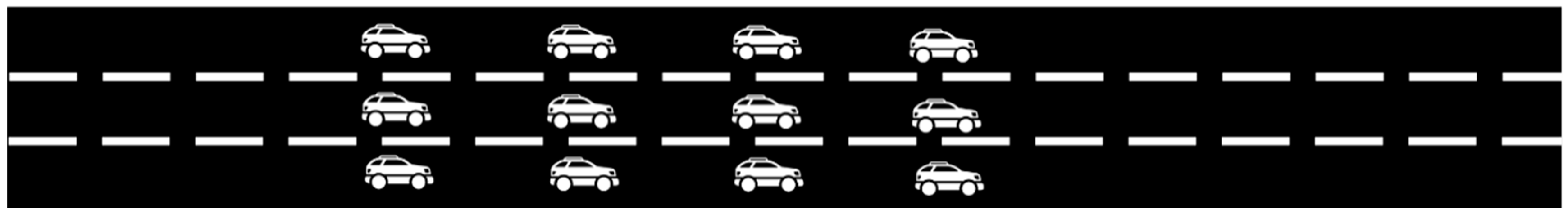
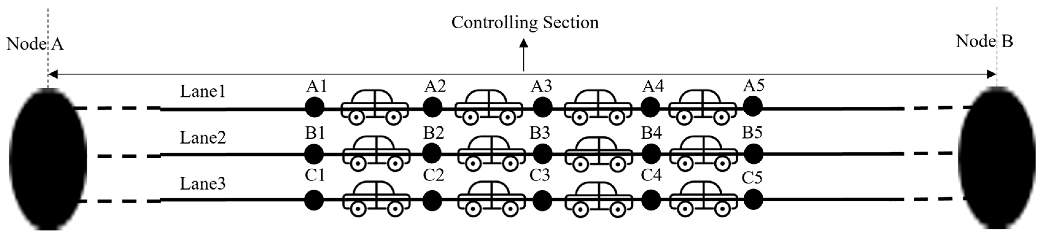
The specific construction process of a virtual track is as shown in Figure 1 and Figure 2 [69]. Any given lane of a section of a highway is divided into sections of 5–10 m long each. The specific value of the interval depends on the traffic characteristics in each region (the denser the traffic flow, the smaller the interval). Each of these intervals is called the “controlling cell”, and so the highway section is divided into several controlling cells. Each controlling cell is occupied by an autonomous vehicle (vehicles with a body length of more than 5 m–10 m can occupy two controlling cells), and at any given time, only one autonomous vehicle is allowed to occupy a controlling cell. In traditional railway control operation, each cell is either occupied or free. For the railway control logic to be followed, we could assume that one cell has to be free between two occupied ones. This may be something to consider in future versions of the work suggested here. The two ends of the controlling cell are marked as “virtual signal machines” (Nodes A1-C5), meaning that once a certain controlling cell is occupied by an autonomous vehicle, a message is transmitted, and the controlling cell is “closed”. This virtual signal machine information transmission is carried out through V2I interactive communication, which is a fundamental operation in the operation of a “virtual track” system.
At the two ends of the highway section that has thus been subdivided into controlling cells, we hypothesize the existence of two “scheduling or dispatching nodes” as shown in Figure 3 (Nodes A and B). The highway section between two scheduling nodes is called the “controlling section”. As new autonomous vehicles drive into the controlling section or others are leaving it, the controlling cells are “occupied” or “freed” and information about the location of the front and the rear of the respective autonomous vehicles is automatically adjusted. Using advanced V2X and V2I communication (through technologies such as satellite positioning, 5G communication, and automatic control technologies), a certain fixed distance interval is maintained between the vehicle ahead and the one behind in the same lane, and also, there is no vacant cell.
The scheduling or dispatching nodes play the role of the (rail) stations and are usually taken to coincide with the highway service areas that are distributed at unequal intervals on the highway network. These play the role of hubs and traffic flow nodes similar to the train stations in a railway system. Therefore, node processing for the virtual track transformation is performed on the highway based on the service area locations.
3.4. Combining Controlling Sections into a Network
In order to control and dispatch autonomous vehicles safely and accurately over a whole network, we have to combine the controlling sections so that we build a virtual network of controlling sections that are connected to each other, and together, they reflect the actual road network. In this way, autonomous vehicles can be better tracked to perform straight driving, turning, changing lanes, and other driving behaviors. For example, the virtual turnout settings at the intersections in the hypothetical highways of Figure 4 can be represented by a total of four controlling sections, with seven service areas (that, based on our previous convention, we consider as “rail stations” and dispatching nodes in our virtual track network). Interval allocation (controlling cells) and node processing are performed on this highway simplified network as described earlier and is shown diagrammatically in Figure 5.
When there is a turn to be taken (turnout point) the virtual representation of the turn is as shown in Figure 6. As shown there, the adjacent controlling cells of different lanes in the two merging highway sections are connected through the form of “virtual turnout” connectors. During the connection process, a new control range called “virtual turnout” is formed to virtually realize the turn through controlling the corresponding cells in the path. For example, if the autonomous vehicle in the control cell “D1-D2” wants to turn and occupy the corresponding cell in another lane, e.g., cell A3-A4 (it might also join B2-B3 if so wanted, or any other cell) the following sequence has to be followed: D1-D2 “-” D2-C1 “-” C1-B2 “-” B2-A3 “-” A3-A4.
Before this sequence starts to be implemented, the system needs to determine the “occupancy locking” situation of the receiving controlling cells through signal information exchange and V2X and V2I information exchange communication. The autonomous vehicle control system collects and processes the necessary data. If the receiving controlling cell is not occupied by another autonomous vehicle, that is if it is not “locked”, the turning autonomous vehicle can enter this cell and corresponding section, otherwise a delay occurs, and the path needs to be readjusted.
After the interval distribution, the node processing, and the virtual turnout settings are completed, the virtual-track scene of the whole highway is set, and the transformation of the road travel scene to a railway travel scene has been completed. At that stage, the railway train operation control ideas and methods can be used to manage and control the autonomous vehicles movement on the highway. Because, in the virtual track, the lanes of the highway are composed of the controlling cells, that is of multiple units, the timetable plan and the method of running graphs of railway train operation control can be used. Under the movement operation in virtual tracks, the safety of autonomous vehicles no longer relies only on the perception, planning, and decision-making of the individual vehicle, but also relies on the overall organizational scheduling and control of a railway-like control center.
In addition, through the signal control and vehicle queue mechanism under the virtual track conditions, the autonomous vehicles running on the highway can be grouped into formations and use integrated autonomous vehicle control system algorithms and accident safe controls.
3.5. “Virtual Track” Autonomous Vehicle Management and Control
After the construction of the virtual tracks network, the autonomous vehicles are converted to virtual train wagons running on a railway track and network. The management and control of their movement can now be studied and solved in terms of the thinking and methods of railway train operation control and scheduling. Wei et al. [56], Lu et al. [70], and Lu et al. [71] have made useful research and analysis work in suggesting such rail control and management algorithms based on methods of railway centralized organizational dispatching with good results. They have respectively used Newell’s simplified car-following model and specialized algorithms based on the “rolling horizon” approach and hierarchical modeling framework to solve the problem of trajectory optimization of autonomous vehicles or platoons considering the thinking of railway train operation control.
This paper uses another method, the spatio-temporal trajectory diagram, to optimize the method of controlling the autonomous vehicles’ movement as they are running in the virtual trackway scene. The temporal-spatial trajectory diagram is an adaptive improvement method of the virtual train movement as it runs in each controlling section of the highway by use of a two-dimensional line diagram that represents the operation of autonomous vehicles in various sections of the highway and the state of stopping or passing at a certain node. The temporal-spatial trajectory preparation is an important implementation tool for introducing the virtual railway train operation control ideas and methods into the field of autonomous driving. In essence, it is an extension of the railway train diagram method in the field of autonomous driving [69]. The temporal-spatial trajectory diagram accurately represents the time and space relationship of autonomous vehicles running on highways and provides a tool for supporting the control of autonomous vehicles running on virtual-tracked highways, as well as visual means and soft support for the organization and scheduling process of large-scale autonomous vehicles movement in highway environments.
Considering that autonomous vehicles on the road form an autonomous vehicle fleet according to the queue arrangement, the total operating cost of the vehicle will be reduced, and the stability, flexibility, and traffic efficiency of the whole autonomous fleet system will be improved [56]. Therefore, in this paper, in the process of controlling large-scale autonomous vehicles by adopting the virtual track and the temporal-spatial trajectory diagram methods, autonomous vehicles will be combined into vehicle formations according to certain queue rules and then efficiently controlled as they are moving like trains on tracks. This is the extension of the applicability of the railway train timetable and train diagram method in the field of autonomous driving on a road network.
4. Model Construction and Testing Based on Virtual Track Concept
4.1. Symbol Definition
The parameters and variables involved in the virtual track model that was built according to the above are shown in Table 2. The application of the relevant parameters and variables is shown in detail in the next section.
4.2. Construction of the Model
4.2.1. Constraint Conditions
The autonomous vehicle management and control model that is constructed for the optimization of the virtual track-based movement of autonomous vehicle platoons on a road network has to respect the following constraints:
(1) Flow balance constraints (relative to the vehicle (or group of vehicles) flows in and out of a controlling cell). The value of the left part (difference between entering and leaving flows) will be −1 when all vehicles arriving at point (i) are less than all vehicles leaving, and +1 when all vehicles arriving are more than all vehicles leaving it. It will be zero otherwise.
(2) Vehicle-following safety constraints (to ensure a safe distance between the vehicle (or group of vehicles) ahead and the one behind in the same lane).
(3) The single vehicle (or group of vehicles) occupancy constraint (it ensures that no two different vehicles (or group of vehicles) occupy the vertex of the same cell (space-time arc) at the same time.
(4) Binary decision variable constraints (to ensure that the decision variable is a 0-1 variable).
(5) Virtual track scene constraints (to ensure that no matter which level of automation the autonomous vehicle (or group of vehicles) belongs to, whether it is manual driving, semi-autonomous driving or fully autonomous driving, as long as the autonomous vehicle runs on the virtual track road network, there will always be a certain safety distance for the front and rear vehicles to avoid vehicle collisions).
By introducing the above constraints, the proposed model ensures that the application of the virtual track theory is in full alignment with the safety and effectiveness of autonomous vehicle movement and control.
4.2.2. Model Formulation and Objective Function Confirmation
By formulating the objective function of the model, the main aim was to minimize the total running time cost of autonomous vehicles on the road network. Therefore, the objective function and the constraints (i.e., the suggested model as a whole) was formed as follows:
Subject to:
This model is an integer programming model, and optimization software such as the CPLEX solver from IBM ILOG can be used to solve it. This is a high performance solver for Linear Programming (LP), Mixed Integer Programming (MIP) and Quadratic Programming (QP/QCP/MIQP/MIQCP) problems. However, solution difficulties may arise when the number of relevant variables is large.
4.3. Model Verification and Solution in a Simplified Network
The SIMLite software V2.0 developed by Zhou et al. on the basis of DTALite [28] and C# programming were used to verify the model. SIMLite software adopts a macro–micro two-layer network structure, which can evaluate the traffic system from different angles and can be applied to the optimization of autonomous vehicle operation trajectories. This section first uses a road network test case containing 5 nodes and 8 direction sections for testing. The sample graph of the macro-level test road network and the schematic diagram of virtual-tracked micro-level road network are shown in Figure 7 and Figure 8, respectively.
After virtual tracking, as shown in Figure 8, the road network has a total of 1064 nodes (like those numbered A1, A2, etc., in Figure 2) and 2500 intervals (controlling cells). However, this road network after converted to virtual track may have local connection interruptions, which will lead to errors in the final solution results or cause a situation where some vehicles have no feasible paths. Therefore, the SIMLite software is first used to verify the connectivity of the virtual tracked road network. To do this, we provide a set of simple initial OD matrices and road network data files, then run the SIMLite software to perform a road network traffic distribution and analyze the traffic distribution results to check whether the connectivity of the road network is intact.
As shown in Figure 9, these output results show that there is no situation where autonomous vehicles fail to find a feasible path, i.e., all autonomous vehicles have completed the movement process from any starting point to any destination one. This illustrates that in the virtual track network that was created and shown in Figure 8, there are no connectivity problems.
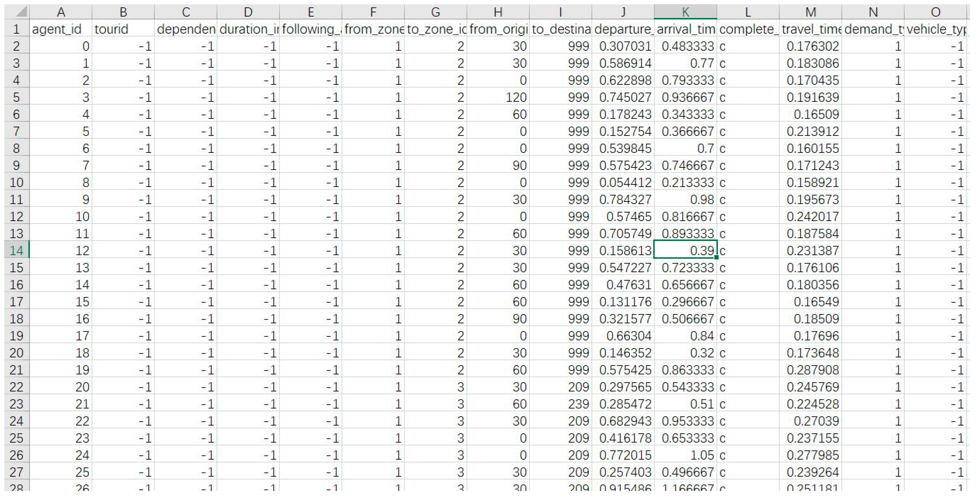
We can now demonstrate the use of the optimization model on a small section of the network in Figure 7 (or its corresponding virtual track one in Figure 8). Let’s consider a section with five controlling cells (depicted as, for example, the four cells in Figure 2). These five cells are delineated by six start and end points which are named points A, B, C, D, E, and F (corresponding to points A1, A2, etc., in Figure 2). Let us now assume that there are 16 autonomous vehicles in the queue to enter the section. We group these vehicles in small platoons of two by two as a demonstration of the platooning that can be done in these cases. Every two vehicles are considered as one unit (platoon of two vehicles). We have eight platoons of autonomous vehicles that want to enter the section. Some of the initial operating schedule data of this autonomous vehicles platoon fleet are shown in Table 3. In this table, the first column indicates the vehicle platoon number, the second column is the entry or exit point number, and the last two columns show the arrival time and departure time of each vehicle platoon in the respective point.
Figure 10 and Figure 11 show the results from the running of the model and the optimization process. Figure 10 shows the temporal-spatial trajectory diagram before and after optimization in a similar way in which we construct these diagrams for the railway tracks. The spatio-temporal trajectories are optimized and solved through the SIMlite software and C# programming. In Figure 10, the temporal-spatial trajectory diagram before optimization is shown in red, and the temporal-spatial trajectory diagram after optimization is shown in green. In order to optimize the function of the algorithm and improve the solution speed, the particle swarm optimization (PSO) method, which was proposed by Kennedy and Eberhart in 1995 [72], was also used.
Figure 11 shows the curve that results when we plot the number of iterations (horizontal axis) and the resulting total travel time cost for the platoons as they move on the section (vertical axis). This curve shows that the total time cost is decreasing from 56,340 secs to 50,258 secs as the number of iterations increases and stabilizes at that number (50,258) after about 50 iterations. This is 6082 secs lower than before, i.e., an optimization ratio of 10.8%.
5. Conclusions and Further Work
This paper has investigated the case of safe and efficient operation of autonomous road vehicles moving on an urban or interurban road network on the basis of virtual track theory. The proposed methodology transforms the autonomous road vehicles’ operation into a railway-like one by converting the road space into “cells” occupied by one vehicle at the time and then grouping these cells into virtual train-like formations that are then managed and controlled like a train scheduled to go from origin point to a destination passing through intermediate “stations” that are the so-called dispatching nodes that, in this paper, are suggested to coincide with the service stations along a highway. The preceding analysis has demonstrated that such transformation is feasible, and there are practical software tools, supported by the proper mathematics, for effecting this conversion from a road movement scene to a railway one. It also demonstrated how one can optimize the whole process and, in this way, provide an efficient and, above all, safe management and control process for the movement of autonomous vehicles on the road networks of the future. The demonstration of the application of the proposed method has—for this case—been made on a hypothetical small-scale network pending a bigger full-scale demo on a real highway network that is to be performed at a next stage.
The full-scale application of the proposed methodology is therefore the first item of future work that must be stressed. There are, however, other improvements that can be mentioned here. In this paper, we used the minimum operating cost of an autonomous vehicle as the target function to minimize when the model is constructed. In the current phase of building the model, the setting of this target function is relatively simple. In the future practical applications in real world situations, this may not be enough, and more target functions could be necessary to be considered. These may include more complicated factors such as the utilization rate of road capacity or overall delays and congestion costs, or generalized costs, etc. Diverse issues like road maintenance time windows would also have to be considered. In future research in this area, therefore, one would need to comprehensively consider multiple factors for inclusion into the optimization process to further improve and supplement the model.
Also, as regards the constraint conditions that were used, the emphasis was given here to constraints that focused on the safety of the vehicles on the virtual-tracked highway. Other constraints that could be tested include the adaptability of the road controlling cells formations to the running control of railway trains, or to the macro-level organizational management and scheduling control of large-scale autonomous vehicle formations. In this way, the application of the virtual track theory will not only ensure the safety but also the effectiveness of the autonomous vehicles’ movement and their management and control through better and more versatile models and algorithms.
Another possible improvement for the future of virtual track theory could be the application of a three-layer conversion of the road network to “macro–meso–micro” levels instead of the current dual-layer. The virtual track theory applied in this paper can carry out macro and micro two-layer transformation of road network, but there is a lack of a layer of transition between macro and micro transformation of road network, which is not conducive to improving the controlling accuracy of autonomous vehicles. In future research, the virtual track theory will be further developed to achieve the goal of “macro–meso–micro” three-layer transformation of the road network, so as to make the autonomous vehicle control scheme more accurate and of high-precision.
Our overall conclusion is that the case of the virtual track theory is a promising avenue for research, offering a convenient railway travel scene in the place of road one by way of simple transformation steps that also include the possibility of (road) vehicle formation into platoons as a way/tool to form something like a train. Once the road movement of autonomous vehicles in the traffic stream has been transformed into a railway-like movement on a track, the use of railway scheduling and solution tools can be used, as demonstrated in this paper. This approach may offer a new angle for autonomous vehicle movement research in the future which, together with the expected progress in high power cloud-computing, super-computing and super-fast information communication (V2X), can make the train-like management and control of the autonomous vehicles (even those running on a mixed traffic scene) both feasible and effective. This paper has focused on methodological issues rather than on models and algorithms as an introduction of the thinking of autonomous driving from the perspective of railway train control. Its preliminary results are encouraging and convincing enough to secure further development and a first real world and larger scale application. This research will be continued, and the theory of virtual tracks will be further developed to hopefully provide an easy and accurate tool for the management and control of autonomous vehicles in our road networks.
Author Contributions
Conceptualization, K.H.; methodology, K.H. and G.G.; software, K.H.; validation, K.H. and G.G.; formal analysis, K.H. and G.G.; resources, K.H. and G.G.; data curation, K.H.; writing—original draft preparation, K.H.; writing—review and editing, K.H. and G.G.; visualization, K.H.; supervision, K.H. and G.G.; project administration, G.G. All authors have read and agreed to the published version of the manuscript.
Funding
This research received no external funding.
Institutional Review Board Statement
Not applicable.
Informed Consent Statement
Not applicable.
Data Availability Statement
No new data were created or analyzed in this study. Data sharing is not applicable to this article.
Acknowledgments
This research was conducted with the support of China Association of Productivity Promotion Centers (CPPC) in China and profited from discussions and experience from the EU funded project SHOW (Shared automation Operating models for worldwide adoption).
Conflicts of Interest
The authors declare no conflicts of interest.
References
Dumas, Y.; Desrosiers, J.; Soumis, F. The pickup and delivery problem with time windows. Eur. J. Oper. Res.1991, 54, 7–22. [Google Scholar] [CrossRef]
Psaraftis, H.N. A dynamic programming approach to the single-vehicle, many-to-many immediate request dial-a-ride problem. Transp. Sci.1991, 14, 130–154. [Google Scholar] [CrossRef]
Ropke, S.; Cordeau, J.-F.; Laporte, G. Models and branch-and-cut algorithms for pickup and delivery problems with time windows. Networks2007, 49, 258–272. [Google Scholar] [CrossRef]
Ropke, S.; Cordeau, J.-F. Branch and cut and price for the pickup and delivery problem with time windows. Transp. Sci.2009, 43, 267–286. [Google Scholar] [CrossRef]
Savelsbergh, M.W.P.; Sol, M. The General Pickup and Delivery Problem. Transp. Sci.1995, 29, 17–29. [Google Scholar] [CrossRef]
Baldacci, R.; Mingozzi, A.; Wolfler-Calvo, R. An exact method for the capacitated location-routing problem. Oper. Res.2011, 59, 1284–1296. [Google Scholar] [CrossRef]
Visentini, M.S.; Borenstein, D.; Li, J.Q.; Mirchandani, P.B. Review of real-time vehicle schedule recovery methods in transportation services. J. Sched.2013, 17, 541–567. [Google Scholar] [CrossRef]
Alvarez, L.; Horowitz, R. Safe platooning in automated highway systems part I: Safety regions design -Vehicle System Dynamics. Veh. Syst. Dyn.1999, 32, 23–55. [Google Scholar] [CrossRef]
Horowitz, R.; Varaiya, P. Control design of an automated highway system. Proc. IEEE2020, 88, 913–925. [Google Scholar] [CrossRef]
Lioris, J.; Pedarsani, R.; Tascikaraoglu, F.Y.; Varaiya, P. Platoons of connected vehicles can double throughput in urban roads. Transp. Res. Part C Emerg. Technol.2017, 77, 292–305. [Google Scholar] [CrossRef]
Hunt, P.B.; Robertson, D.I.; Bretherton, R.D.; Winton, R.I. SCOOT-a Traffic Responsive Method of Coordinating Signals. In the Proceedings of the TRB Annual Meeting. Available online: https://trid.trb.org/view/179439 (accessed on 2 February 2024).
Lowrie, P.R. SCATS: Sydney Co-Ordinated Adaptive Traffic System: A Traffic Responsive Method of Controlling Urban Traffic. Available online: https://trid.trb.org/view.aspx?id=488852 (accessed on 2 February 2024).
Gartner, N.H. OPAC: A demand-responsive strategy for traffic signal control. Transp. Res. Rec.1983, 906, 75–81. [Google Scholar]
Gartner, N.H.; Stamatiadis, C. Arterial-Based Control of Traffic Flow in Urban Grid Networks. Math. Comput. Model.2002, 35, 657–671. [Google Scholar] [CrossRef]
Mirchandani, P.B.; Head, K.L. A Real-Time Traffic Signal Control System: Architecture, Algorithms, and Analysis. Transp. Res. Part C2001, 9, 415–432. [Google Scholar] [CrossRef]
Dell’Olmo, P.; Mirchandani, P.B. REALBAND: An approach for real-time coordination of traffic flows on networks. Transp. Res. Rec.1995, 1494, 106–116. [Google Scholar]
He, Q.; Head, K.L.; Ding, J. PAMSCOD: Platoon-based arterial multi-modal signal control with online data. Transp. Res. Part C Emerg. Technol.2012, 20, 164–184. [Google Scholar] [CrossRef]
Papageorgiou, M.; Haj-Salem, H.; Blosseville, J.-M. ALINEA: A Local Feedback Control Law for On-Ramp Metering. Transp. Res. Rec.1991, 1320, 58–64. [Google Scholar]
Gettman, D. A Multiobjective Integrated Large-Scale Optimized Ramp Metering Control System for Freeway/Surface-Street Traffic Management. Ph.D. Thesis, University of Arizona, Tucson, AZ, USA, 1998. [Google Scholar]
Zhou, J.; Zhu, F. Analytical analysis of the effect of maximum platoon size of connected and automated vehicles. Transp. Res. Part C2021, 122, 102882. [Google Scholar] [CrossRef]
Ma, G.; Wang, B.; Ge, S.S. Robust optimal control of connected and automated vehicle platoons through improved particle swarm optimization. Transp. Res. Part C2022, 135, 103488. [Google Scholar] [CrossRef]
Shen, J.; Kammara, E.K.H.; Du, L. Fully distributed optimization-based CAV platooning control under linear vehicle dynamics. Transp. Sci.2022, 56, 381–403. [Google Scholar] [CrossRef]
Wang, J.; Lu, L.; Peeta, S. Real-time deployable and robust cooperative control strategy for a platoon of connected and autonomous vehicles by factoring uncertain vehicle dynamics. Transp. Res. Part B2022, 163, 88–118. [Google Scholar] [CrossRef]
Zhang, H.; Du, L.; Shen, J. Hybrid MPC system for platoon based cooperative lane change control using machine learning aided distributed optimization. Transp. Res. Part B2022, 159, 104–142. [Google Scholar] [CrossRef]
Ziliaskopoulos, A.; Waller, S.T. An Internet-based geographic information system that integrates data, models and users for transportation applications. Transp. Res. Part C2000, 8, 427–444. [Google Scholar] [CrossRef]
Mahmassani, H.S.; Qin, X.; Zhou, X. DYNASMART-X Evaluation for Real-Time TMC Application: Irvine Test Bed; US DOT/FHWATREPS Phase 1.5B Final Report; Maryland Transportation Initiative, University of Maryland: College Park, MA, USA, 2004. [Google Scholar]
Ben-akiva, M.; Bierlaire, M.; Koutsopoulos, H.N.; Mishalani, R. Real Time Simulation of Traffic Demand-Supply Interactions within DynaMIT. In Transportation and Network Analysis: Current Trends; Gendreau, M., Marcotte, P., Eds.; Kluwer Academic Publishers: New York, NY, USA, 2002; pp. 19–36. [Google Scholar]
Zhou, X.; Taylor, J.; Pratico, F. DTALite: A Queue-Based Mesoscopic Traffic Simulator for Fast Model Evaluation and Calibration. Cogent Eng.2014, 1, 1. [Google Scholar] [CrossRef]
Ziliaskopoulos, A.K.; Waller, S.T.; Li, Y.; Byram, M. Large Scale Dynamic Traffic Assignment: Implementation Issues and Computational Analysis. J. Transp. Eng.2004, 130, 585–593. [Google Scholar] [CrossRef]
Gao, S.; Chabini, I. The best routing policy problem in stochastic time-dependent networks. Transp. Res. Part B2002, 14, 93–122. [Google Scholar] [CrossRef]
Unnikrishnan, A.; Waller, S.T. User Equilibrium with Recourse. Netw. Spat. Econ.2009, 9, 575–593. [Google Scholar] [CrossRef]
Lin, D.Y.; Unnikrishnan, A.; Waller, S.T. A Dual Variable Approximation Based Heuristic for Dynamic Congestion Pricing. Netw. Spat. Econ.2011, 11, 271–293. [Google Scholar] [CrossRef]
Peeta, S.; Ziliaskopoulos, A. Foundations of dynamic traffic assignment: The past, the present and the future. Netw. Spat. Econ.2001, 1, 233–266. [Google Scholar] [CrossRef]
Reuschel, A. Vehicle movements in a platoon with Uniform Acceleration or Deceleration of the Lead Vehicle. Oesterreichisches Ing.-Arch.1950, 4, 193–215. [Google Scholar]
Pipes, L.A. An operational analysis of dynamics. J. Appl. Phys.1953, 24, 274–287. [Google Scholar] [CrossRef]
Kometani, E.; Sasaki, T. Dynamic behaviour of traffic with a nonlinear spacing-speed relationship. In Proceedings of the Symposium on Theory of Traffic Flow held at General Motors Research Laboratories; Elsevier Science Publishers: Amsterdam, The Netherlands, 1959; pp. 105–119. [Google Scholar]
Newell, G.F. A simplified vehicle-following theory: A lower order model. Transp. Res. Part B Methodol.2002, 36, 195–205. [Google Scholar] [CrossRef]
Newell, G.F. A simplified theory of kinematic waves in highway traffic, part I: General theory. Transp. Res. Part B Methodol.1993, 27, 281–287. [Google Scholar] [CrossRef]
Ahn, S.; Cassidy, M.J.; Laval, J. Verification of a simplified vehicle-following theory. Transp. Res. Part B Methodol.2004, 38, 431–440. [Google Scholar] [CrossRef]
Zhou, H.; Zhou, A.; Li, T.; Chen, D.; Peeta, S.; Laval, J. Congestion-mitigating MPC design for adaptive cruise control based on Newell’s car following model: History outperforms prediction. Transp. Res. Part C2022, 142, 103801. [Google Scholar] [CrossRef]
Stevens, W.B. The Automated Highway System Program: A Progress Report. IFAC Proc. Vol.1996, 29, 8180–8188. [Google Scholar] [CrossRef]
Bose, A.; Ioannou, P. Analysis of traffic flow with mixed manual and semi-automated vehicles. IEEE Trans. Intell. Transp. Syst.2003, 4, 173–188. [Google Scholar] [CrossRef]
Ward, J.D. Step by Step to an Automated Highway System—and Beyond. In Automated Highway Systems; Springer: Boston, MA, USA, 1997; pp. 73–91. [Google Scholar]
Talebpour, A.; Mahmassani, H.S. Influence of autonomous and connected vehicles on stability of traffic flow. In Proceedings of the Transportation Research Board 94th Annual Meeting, Washington, DC, USA, 11–15 January 2015. [Google Scholar]
Milanés, V.; Shladover, S.E. Modeling cooperative and autonomous adaptive cruise control dynamic responses using experimental data. Transp. Res. Part C Emerg. Technol.2014, 48, 285–300. [Google Scholar] [CrossRef]
Betts, J.T. Survey of numerical methods for trajectory optimization. J. Guid. Control Dyn.1998, 21, 193–207. [Google Scholar] [CrossRef]
Flint, M.; Polyvehiclepou, M.; Fernandez-Gaucherand, E. Cooperative Path-Planning for Autonomous Vehicles Using Dynamic Programming. In Proceedings of the IFAC 15th Triennial World Congress, Barcelona, Spain, 21–26 July 2002; pp. 1694–1699. [Google Scholar]
Schouwenaars, T.; De Moor, B.; Feron, E.; How, J. Mixed Integer Programming for Multi-Vehicle Path Planning. In Proceedings of the Control Conference (ECC), Porto, Portugal, 4–7 September 2001; pp. 2603–2608. [Google Scholar]
Guo, Y.; Parker, L.E. A Distributed and Optimal Motion Planning Approach for Multiple Mobile Robots. In Proceedings of the Robotics and Automation, Washington, DC, USA, 11–15 May 2002; pp. 2612–2619. [Google Scholar]
McNaughton, M. Parallel Algorithms for Real-Time Motion Planning. Ph.D. Dissertation, Vehiclenegie Mellon University, Pittsburgh, PA, USA, 2011. [Google Scholar]
Gong, S.; Shen, J.; Du, L. Constrained optimization and distributed computation-based vehicle following control of a connected and autonomous vehicle platoon. Transp. Res. Part B Methodol.2016, 94, 314–334. [Google Scholar] [CrossRef]
Bang, S.; Ahn, S. Platooning strategy for connected and autonomous vehicles: Ransition from light traffic. Transp. Res. Rec.2017, 2623, 73–81. [Google Scholar] [CrossRef]
Zhou, F.; Li, X.; Ma, J. Parsimonious shooting heuristic for trajectory design of connected automated traffic part I: Theoretical analysis with generalized time geography. Transp. Res. part B Methodol.2017, 95, 394–420. [Google Scholar] [CrossRef]
Wei, Y.; Avcı, C.; Liu, J.; Belezamo, B.; Aydın, N.; Li, P.T.; Zhou, X. Dynamic programming-based multi-vehicle longitudinal trajectory optimization with simplified vehicle following models. Transp. Res. Part B Methodol.2017, 106, 102–129. [Google Scholar] [CrossRef]
Wang, J. High Efficiency and High Precision Research on the Integration of High-Speed Railway Train Timetabling Problem. Ph.D. dissertation, Beijing Jiaotong University, Beijing, China, 2020.
Brännlund, U.; Lindberg, P.O.; Nõu, A. Railway Timetabling Using Lagrangian Relaxation. Transp. Sci.1998, 32, 358–369. [Google Scholar] [CrossRef]
Caprara, A.; Fischetti, M.; Toth, P. Modeling and solving the train timetabling problem. Oper. Res.2002, 50, 851–861. [Google Scholar] [CrossRef]
Caprara, A.; Monaci, M.; Toth, P.; Guida, P.L. A Lagrangian heuristic algorithm for a real-world train timetabling problem. Discret. Appl. Math.2006, 154, 738–753. [Google Scholar] [CrossRef]
D’Ariano, A.; Pacciarelli, D.; Pranzo, M. Assessment of flexible timetables in real-time traffic management of a railway bottleneck. Transp. Res. Part C2007, 16, 232–245. [Google Scholar] [CrossRef]
Zhou, X.; Zhong, M. Single-track train timetabling with guaranteed optimality: Branch-and-bound algorithms with enhanced lower bounds. Transp. Res. Part B Methodol.2007, 41, 320–341. [Google Scholar] [CrossRef]
Liu, S.Q.; Kozan, E. Scheduling trains with priorities: A no-wait blocking parallel-machine job-shop scheduling model. Transp. Sci.2011, 45, 175–198. [Google Scholar] [CrossRef]
Petersen, H.L.; Larsen, A.; Madsen, O.B.; Petersen, B.; Ropke, S. The Simultaneous Vehicle Scheduling and Passenger Service Problem. Transp. Sci.2013, 47, 603–616. [Google Scholar] [CrossRef]
Sun, Y.; Cao, C.; Wu, C. Multi-objective optimization of train routing problem combined with train scheduling on a high-speed railway network. Transp. Res. Part C Emerg. Technol.2014, 44, 1–20. [Google Scholar] [CrossRef]
Meng, L.; Zhou, X. Simultaneous train rerouting and rescheduling on an N -track network: A model reformulation with network-based cumulative flow variables. Transp. Res. Part B Methodol.2014, 67, 208–234. [Google Scholar] [CrossRef]
Yang, L.; Qi, J.; Li, S.; Gao, Y. Collaborative optimization for train scheduling and train stop planning on high-speed railways. Omega2015, 64, 57–76. [Google Scholar] [CrossRef]
Tang, J.; Hou, K. An autonomous driving technology based on highway virtual track. C.N. Patent ZL 201910074327, 18 December 2020. [Google Scholar]
Lu, G.; Nie, Y.M.; Liu, X.; Li, D. Trajectory-based traffic management inside an autonomous vehicle zone. Transp. Res. Part B Methodol.2019, 120, 76–98. [Google Scholar] [CrossRef]
Lu, J.; Zhou, X. Virtual track networks: A hierarchical modeling framework and open-source tools for simplified and efficient connected and automated mobility (CAM) system design based on general modeling network specification (GMNS). Transp. Res. Part C Emerg. Technol.2023, 153, 104223. [Google Scholar] [CrossRef]
Kennedy, J.; Eberhart, R. Particle Swarm Optimization. In Proceedings of the ICNN’95—International Conference on Neural Networks, Perth, WA, Australia, 27 November–1 December 1995; Volume 4, pp. 1942–1948. [Google Scholar] [CrossRef]
Figure 1.
Schematic diagram of the highway section.
Figure 1.
Schematic diagram of the highway section.
Figure 2.
Highway cell allocation for the virtual track preparation.
Figure 2.
Highway cell allocation for the virtual track preparation.
Figure 3.
Highway node processing.
Figure 3.
Highway node processing.
Figure 4.
Schematic diagram of partial highway network.
Figure 4.
Schematic diagram of partial highway network.
Figure 5.
Cell allocation and dispatching node processing for the highway network of Figure 4.
Figure 5.
Cell allocation and dispatching node processing for the highway network of Figure 4.
Figure 6.
Highway virtual turnout setting.
Figure 6.
Highway virtual turnout setting.
Figure 7.
Schematic graph of macro-level road network.
Figure 7.
Schematic graph of macro-level road network.
Figure 8.
Schematic diagram of virtual-tracked micro-level road network.
Figure 8.
Schematic diagram of virtual-tracked micro-level road network.
Figure 9.
The partial display of SIMLite output file for the simple “virtual track” converted network of Figure 8.
Figure 9.
The partial display of SIMLite output file for the simple “virtual track” converted network of Figure 8.
Figure 10.
Display of temporal-spatial trajectory diagram before and after optimization.
Figure 10.
Display of temporal-spatial trajectory diagram before and after optimization.
Figure 11.
Results of the optimization runs for the five cell 2-vehicle platoon case.
Figure 11.
Results of the optimization runs for the five cell 2-vehicle platoon case.
Table 1.
Road traffic accidents caused by autonomous driving in recent years.
Table 1.
Road traffic accidents caused by autonomous driving in recent years.
NO.
Company
Time
Location
Description of Accident
Severity
1
Tesla
20 January 2016
Handan section of Beijing-Hong Kong-Macao Highway, Hebei Province, China
The autonomous vehicle, which had the “autopilot” function activated, rear-ended a road sweeper in the first lane while it was working
Autonomous vehicle driver killed
2
Google
14 February 2016
Mountain View, CA, USA
The autonomous vehicle changed lanes and collided with a bus during operational tests
The left side of the autonomous vehicle was damaged, and there were no casualties
3
Tesla
May 2016
A no-signal control intersection in Williston, FL, USA
The autonomous vehicle was in the active state of “autopilot” function and collided with a trailer that was traveling in a vertical direction
Autonomous vehicle driver killed
4
Google
23 September 2016
Mountain View, CA, USA
The autonomous vehicle was hit by a van that ran a red light at an intersection during operational tests
Both vehicles were badly damaged
5
Uber
17 July 2017
Tempe, AZ, USA
The autonomous vehicle collided with a vehicle turning left in a vertical direction at an intersection during operational tests
Two vehicles were damaged
6
Google
26 August 2017
Palo Alto, CA, USA
The vehicle in front of the autopilot suddenly changed lanes to avoid obstacles on the road, and the autopilot vehicle then changed lanes to the right and scratched the vehicle behind it
Two vehicles were damaged
7
Uber
19 March 2018
Tempe, AZ, USA
The autonomous vehicle hit a pedestrian crossing the road during an operational test
Pedestrian death
8
Tesla
23 March 2018
Us Highway 101
The autonomous vehicle was in the active state of “autopilot” function and hit the center barrier
The autonomous vehicle caught fire and the driver was killed
9
Google
4 May 2018
Chandler, AZ, USA
The autonomous vehicle traveling in the opposite direction entered the lane of the autonomous vehicle and collided with it
Two vehicles were damaged, and passengers suffered minor injuries
10
Google
16 June 2018
Mesa, AZ, USA
The autonomous vehicle was hit by a vehicle running a red light, and a multi-vehicle pileup occurred
Multiple vehicles were damaged
11
Apple
24 August 2018
Sunnyvale, CA, USA
The autonomous vehicle was rear-ended when it merged into traffic on the road
Two vehicles were damaged
12
Tesla
20 January 2020
Pleasanton, CA, USA
Autonomous vehicles collided with traffic lights and concrete walls
Autonomous vehicle driver killed
Table 2.
Notation used for parameters and variables of the virtual track model.
Table 2.
Notation used for parameters and variables of the virtual track model.
Parameter
Definition
Index of physical node
Index of the physical path from node i to node j
Index of vehicle
Index of Time interval
Set of nodes in a physical network
Set of paths in a physical network
Set of vertices in a time-space network
Set of arcs in a time-space network
Set of vehicles
Set of Vehicle automation class, G= {0, 1, 2, 3, 4, 5}
Set of arcs occupying vertices (k,p)
Starting node of the vehicle of
Target node of the vehicle
Departure time interval of the vehicle
Automation level of the vehicle , G()∈G
Safe distance between front and rear vehicles
A large real number, the value depends on the specific traffic scenario
Range of time interval
The cost of the vehicle traveling on arc (i,j), arrival time t, and departure time s
A binary variable indicating whether the vehicle is traveling on an arc (i,j) with arrival time t and departure time s
A binary variable indicating whether vehicle occupies the vertex of space-time (k,p)
A binary variable indicating whether vehicle are operating on a Virtual-tracked road network
Table 3.
Operating/scheduling data of the virtual vehicle platooning (Part of data).
Table 3.
Operating/scheduling data of the virtual vehicle platooning (Part of data).
Vehicle Platoon Number
Node
Arrival Time
Departure Time
1
A
12:01:30
12:02:05
1
B
12:03:40
12:04:15
1
C
12:05:30
12:06:12
1
D
12:07:32
12:08:27
1
E
12:09:39
12:10:14
1
F
12:11:24
12:12:02
2
A
12:05:55
12:06:30
2
B
12:08:05
12:08:40
2
C
12:09:55
12:10:37
2
D
12:11:57
12:12:52
2
E
12:14:04
12:14:39
2
F
12:15:49
12:16:27
3
A
12:10:20
12:10:55
3
B
12:12:30
12:13:05
3
C
12:14:20
12:15:02
3
D
12:16:22
12:17:17
3
E
12:18:29
12:19:04
3
F
12:20:14
12:20:52
4
A
12:14:45
12:15:20
4
B
12:16:55
12:17:30
4
C
12:18:45
12:19:27
4
D
12:20:47
12:21:42
4
E
12:22:54
12:23:29
4
F
12:24:39
12:25:17
5
A
12:19:10
12:19:45
5
B
12:21:20
12:21:55
5
C
12:23:10
12:23:52
5
D
12:25:12
12:26:07
5
E
12:27:19
12:27:54
5
F
12:29:04
12:29:42
6
A
12:23:35
12:24:10
6
B
12:25:45
12:26:20
6
C
12:27:35
12:28:17
6
D
12:29:37
12:30:32
6
E
12:31:44
12:32:19
6
F
12:33:29
12:34:07
7
A
12:28:00
12:28:35
7
B
12:30:10
12:30:45
7
C
12:32:00
12:32:42
7
D
12:34:02
12:34:57
7
E
12:36:09
12:36:44
7
F
12:37:54
12:38:32
8
A
12:32:25
12:33:00
8
B
12:34:35
12:35:10
8
C
12:36:25
12:37:07
8
D
12:38:27
12:39:22
8
E
12:40:34
12:41:09
8
F
12:42:19
12:42:57
Disclaimer/Publisher’s Note: The statements, opinions and data contained in all publications are solely those of the individual author(s) and contributor(s) and not of MDPI and/or the editor(s). MDPI and/or the editor(s) disclaim responsibility for any injury to people or property resulting from any ideas, methods, instructions or products referred to in the content.


