Article

Multi-Task Vehicle Platoon Control: A Deep Deterministic Policy Gradient Approach

by
Mehran Berahman
1,
Majid Rostami-Shahrbabaki
2,* and
Klaus Bogenberger
2
1
Department of Electrical and Computer Engineering, Shiraz University, Shiraz 51154-71348, Iran
2
Chair of Traffic Engineering and Control, Technical University of Munich, 80333 Munich, Germany
*
Author to whom correspondence should be addressed.
Future Transp. 2022, 2(4), 1028-1046; https://doi.org/10.3390/futuretransp2040057
Submission received: 25 October 2022 / Revised: 27 November 2022 / Accepted: 8 December 2022 / Published: 12 December 2022

Abstract

:
Several issues in designing a vehicle platoon control system must be considered; among them, the speed consensus and space/gap regulation between the vehicles play the primary role. In addition, reliable and fast gap-closing/opening actions are highly recommended for establishing a platoon system. Nonetheless, the lack of research on designing a single algorithm capable of simultaneously coping with speed-tracking and maintaining a secure headway, as well as the gap-closing/opening problems, is apparent. As deep reinforcement learning (DRL) applications in driving strategies are promising, this paper develops a multi-task deep deterministic policy gradient (DDPG) car-following algorithm in a platoon system. The proposed approach combines gap closing/opening with a unified platoon control strategy; as such, an effective virtual inter-vehicle distance is employed in the developed DRL-based platoon controller reward. This innovative new distance definition, which is based on the action taken by the ego-vehicle, leads to a precise comprehension of the agent’s actions. Moreover, by imposing a specific constraint on a variation of the ego-vehicle’s relative speed with respect to its predecessor, the speed chattering of the ego-vehicle is reduced. The developed algorithm is implemented in the realistic traffic simulator, SUMO (Simulation of Urban Mobility), and the performance of the developed control strategy is evaluated under different traffic scenarios.

1. Introduction

The evolution of transportation systems has brought convenience to daily life, allowing goods and passengers to be quickly transported domestically and internationally. Consequently, this development has led to a considerable number of vehicles in the transportation systems. This causes transportation systems to encounter enormous challenges in the 21st century, namely, the increasing number of highway accidents, commuting hours, and energy consumption in traffic congestion.
The advent of connected and automated vehicles (CAVs) could mitigate the issues mentioned above in the current transportation systems. CAVs offer the possibility of introducing new traffic control and management approaches, thanks to their highly precise sensors and intelligent technologies for fast and reliable vehicle-to-vehicle (V2V) and vehicle-to-infrastructure (V2I) communication. Given that CAVs could share their measurements and variables using V2V communication, they could form platoons, in which the vehicles drive with a very short headway and a similar speed. Platooning results in fuel savings and increased road capacity [1]. In a CAV platoon, the vehicles move at a consensual speed while maintaining the desired space between adjacent vehicles [2]. Platooning paves the way for many other use cases, including vehicle-to-vehicle charging [3]. It is also noteworthy that, by receiving extra information such as downstream traffic conditions, it is possible to plan the trajectory of a platoon optimally, e.g., the occurrence of smooth deceleration as downstream congestion is detected [4], or to minimize fuel consumption based on a given road inclination [5].
Adaptive Cruise Control (ACC) is the most straightforward platoon controller to maintain a safe distance for a vehicle from its preceding counterpart. Platoon control is usually designed based on a distributed controller called Cooperative Adaptive Cruise Control (CACC) [6], which requires information from the preceding vehicles to achieve a global consensus in terms of vehicle movement. Five principal approaches are the most recommended approaches for designing a platoon controller, including linear [7], h1-based [8], optimal [9], model predictive [10], and the sliding mode [11]. Recently, autonomous vehicle driving strategies based on learning approaches have received much attention, due to the merit of exploring complex and unknown state spaces. One such learning approach is reinforcement learning based on the Markov decision process (MDP), where the agent’s goal is to learn a state-action mapping policy to maximize the long-term cumulative reward [12]. Applying reinforcement learning in driving strategies, such as car-following, demonstrates significant improvement in their performance [13,14].
Combining deep (multi-layer) neural networks with the decision-making capabilities of reinforcement learning establishes the deep reinforcement learning (DRL) algorithm. DRL approximates the optimal state-action policy based on trial and error, as the agent interacts with the environment during training [15]. In order to utilize DRL in a multi-dimensional continuous state and action space, a deep deterministic policy gradient (DDPG) is proposed [16]. In a platoon system, gap-closing/opening manoeuvres are unavoidable, which occur between a merging vehicle and an in-platoon vehicle, or at the end of a splitting scenario; thus, a vehicle should be able to close or open an inter-vehicle distance gap. Even though gap closing/opening is one of the requirements in platoon creation, the lack of research on designing a specific algorithm that could concurrently cope with speed-tracking and maintaining a secure headway, as well as gap-closing/opening issues, is evident.
Given the mentioned research gap and the capability of the DDPG algorithm in solving control problems, this study designs a platoon control strategy based on the DDPG algorithm. The proposed control algorithm encompasses the three aforementioned main aspects of a platoon, namely, speed-tracking, inter-vehicle constant gap-keeping, and the gap-closing/opening capability in one controller as the main contributions of this research. As such, in the definition of the reward function, a constant distance gap to be maintained during the platoon movement is considered. Moreover, an effective inter-vehicle distance is introduced, based on the actual longitudinal distance of two consecutive vehicles and their speeds. This innovative new distance definition is considered in the definition of the reward function, based on the action taken by the ego-vehicle, and leads to a precise comprehension of the effect of the agent’s actions, i.e., the ego-vehicle’s acceleration/deceleration, on the environment. It is worth mentioning that, by imposing a specific constraint on a variation of the ego-vehicle relative speed, with respect to its predecessor, the speed chattering of the ego-vehicle during the gap-closing/opening manoeuvres, or in the speed-tracking of the leading vehicle, is reduced. This restriction is considered in the training of the DDPG algorithm by defining an extra feature in its reward function. The proposed platoon driving strategy is then conducted in different traffic scenarios, implemented in Simulation of Urban MObility (SUMO) [17], to evaluate its performance.
The outline of this paper is as follows: The related works are documented in Section 2. Section 3 describes the different component frameworks of a platoon system and its control problems. Section 4 introduces the proposed DRL algorithm and its reward function. Then, the results of the introduced DDPG algorithm employed in the platoon system and its performance evaluation are given in Section 5. Finally, Section 6 concludes this paper.

2. Related Work

In recent years, a varied range of RL approaches have been employed as far as CAVs’ control issues are concerned, which can be categorized within three main groups [18]. The first group concentrates on the enhancement of the driving circumstances, established by training automated vehicle agents to learn an efficient and smooth driving policy in terms of car-following and or lane-change manoeuvres [19,20]. In the second category, data-driven methods are deployed to achieve appropriate driving policies for CAVs through existing V2V and vehicle-to-infrastructure communications; human car-following models are formulated by means of the actor–critic-based RL algorithms [14,21]. The last but not least group addresses the CAV’s movement in complex urban scenarios, namely, the automated vehicle’s decision on stop/go at a traffic light, training of the self-driving agents in such cases as parking lot exploration and object-avoidance, and navigating occluded intersections, with the autonomous vehicles using the development of an efficient driving strategy [22,23,24].
In [25], a neural network approximation approach is employed to deal with the inherent nonlinearity in the longitudinal dynamic model of the throughput vehicles. With the aim of coping with the problem of secure distributed adaptive platooning control of automated vehicles over vehicular ad hoc networks (VANETs) in the presence of intermittent denial-of-service attacks, a logical processor was designed, and secure platooning control was achieved. Moreover, in [26], also by considering both lateral and longitudinal dynamics of each vehicle, an adaptive control strategy based on a neural network is presented to compensate for the detriments of unknown data falsification attacks on driving commands in the platooning.
The use of the DDPG algorithm for driving strategies shows advantages, specifically in complex and unknown traffic environments [27]. In [28], a car-following controller is developed through a DDPG by learning from naturalistic human-driving data. In [29], a hybrid car-following strategy is proposed that not only guarantees the basic performance of car-following through CACC but also makes full use of the advantages of exploration of complex environments via a DDPG. In [30], a driving strategy based on an artificial ellipsoid safety border and a DDPG network is developed for the movement of CAVs in a lane-free environment. Its result depicts a considerable improvement in traffic throughput. The platoon control of automated vehicles based on a DDPG is also carried out in [31], in which the ego-vehicle can track the speed of the leading vehicle with a secure longitudinal space gap.
In the case of the platoon splitting and merging, in [32], a CACC, as the main functionality of vehicle-following, is equipped with the additional features of collision avoidance and gap-closing by means of an adopted artificial potential function; a designed controller in this paper integrates a vehicle-following mechanism, gap-closing, and collision-avoidance functionalities in a single controller.
In this work, we introduce a platoon control strategy based on the DDPG algorithm, a control methodology that meets three required functionalities of a vehicular platoon: speed-tracking, inter-vehicle constant gap-keeping, and gap-closing/opening. Therefore, the main contribution of this study is as follows:
  • This study constructs a multi-task approach based on a DDPG framework to control vehicles in a platoon. The main contribution of this work is defining a reward function that allows the implementation of such control tasks.
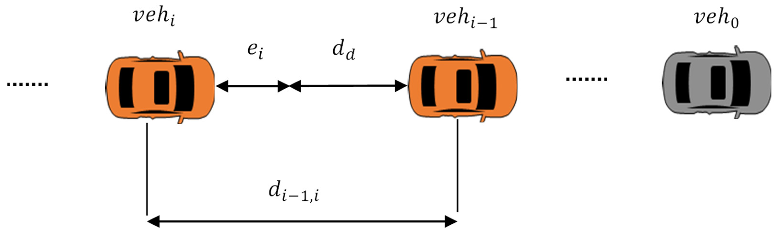
  • Introduction of an effective inter-vehicle distance based on the actual longitudinal distance of two consecutive vehicles and their speed;
  • Imposing a specific constraint on a variation in the ego-vehicle’s relative speed with respect to its predecessor and including that in the developed single reward function; as a result, the speed chattering of the ego-vehicle during the gap-closing/opening manoeuvres, or in the speed-tracking of the leading vehicle, is reduced.
The details of the proposed methodology are described in the following sections.

3. Vehicular Platoon Architecture and Control Problem Statement

A platoon system can be regarded as a combination of four main features: node dynamics (ND), information flow topology (IFT), distributed controller (DC), and formation geometry (FG) [33]. ND describes the longitudinal behaviour of each vehicle. The IFT describes how a vehicle acquires the information about its surrounding vehicles, which has an important impact on the stability of vehicular platooning; the IFT applied in the proposed platoon system is predecessor–follower–leader. In more detail, each ego-vehicle takes the longitudinal speed and position of its preceding and leading vehicles into account to compute its next acceleration. The third feature, i.e., DC, implements a custom controller to achieve the global coordination of the platoon through the neighbour vehicles’ information. This specific controller should meet two internal and string stability requirements of a platoon [33]; in this study, a developed DDPG algorithm plays the role of the platoon DC.
The last feature of a platoon, i.e., the FG, defines the desired inter-vehicle distance while platooning. The FG aspect for a vehicular platoon consists of three major approaches: the constant distance, constant time headway, and nonlinear distance approaches, based on a nonlinear function of the ego-vehicle’s velocity [34]. The constant distance method is used in this research. Since the vehicle’s velocity is not involved in the definition of the desired distance between two consecutive vehicles, deployment of this approach could lead to high traffic-capacity achievement
As mentioned in the previous section, the gap-closing/opening functionality of the vehicle participants in a platoon system is also critical, in addition to the vehicular platoon’s features mentioned above. Therefore, this aspect is included in the distributed control by being involved in the reward function of the introduced DDPG algorithm described in the next section.
The vehicular platoon architecture considered in this study is shown in Figure 1. This platoon system comprises a leading vehicle (named as the leader, with index 0) and N following vehicles (called followers, with indices i = 1 ,   2 ,   .   ,   N ). Additionally, given that the constant distance gap is utilized as the FG facet in this research, a fixed d d (bumper-to-bumper distance) is considered for all the vehicles in the developed platoon system. In the mentioned platoon system, a fundamental car-following control problem is considered; wherein the principal goal of each following vehicle is to maintain its predefined inter-vehicle gap set point, d d , while tracking the leading vehicle’s speed.
To this end, the gap-keeping error for vehicle i is derived as
e i , k = d ( i 1 , i ) , k L d d
where d ( i 1 , i ) , k and L denote the actual longitudinal distance between vehicles i 1 and i at time step k (measured from the centre point of the vehicles) and the length of each vehicle, respectively. Note that, in this study, all the vehicles are assumed to have the same physical shape.
The required actual speed of each vehicle at each time step, v i , k , is computed by considering the acceleration, a i , k 1 , achieved from the proposed DDPG algorithm as follows:
v i , k = v i , k 1 + a i , k 1 + Δ T
where Δ T denotes the sampling time period.

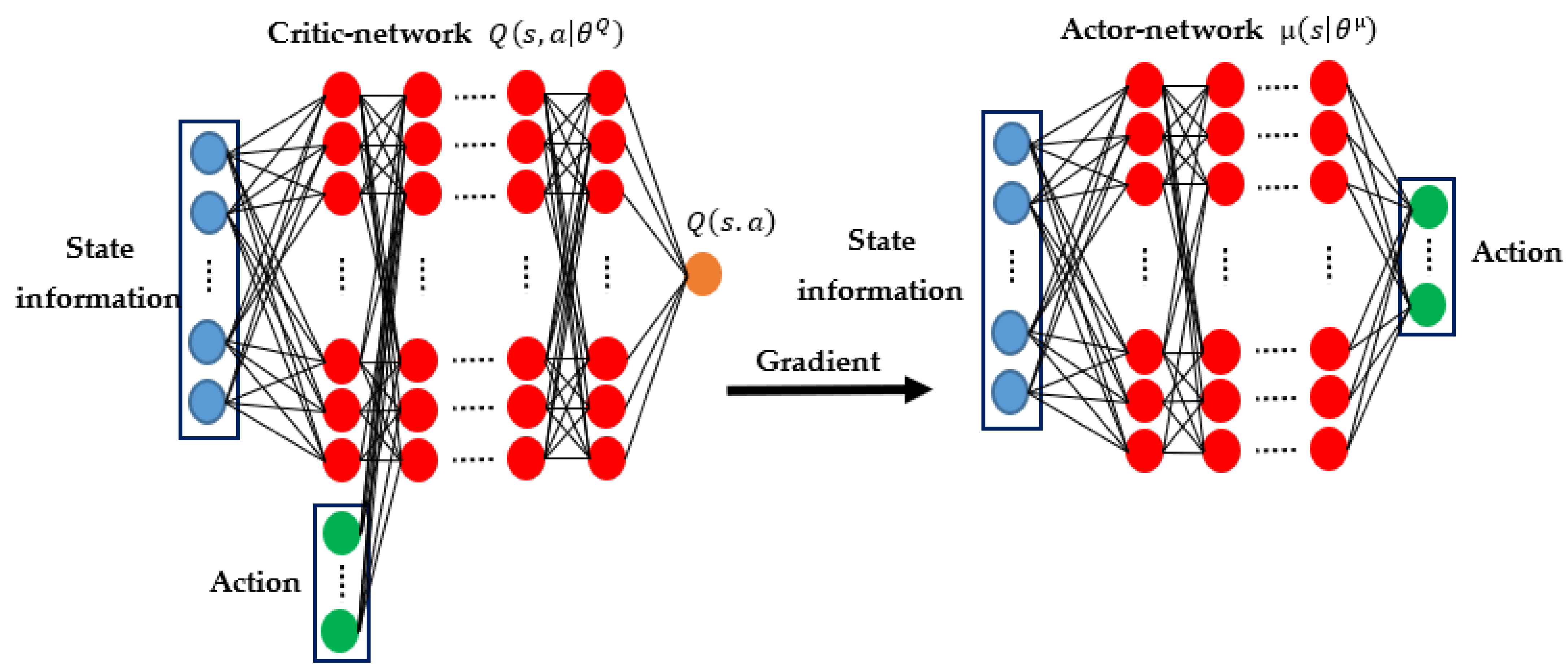
4. Deep Reinforcement Learning Algorithm

This section describes a specific DRL algorithm, called DDPG, for platooning. To this end, the acceleration of each vehicle in a platoon system is computed to satisfy the predefined major objectives of a platoon, including the leading vehicle’s speed-tracking, constant longitudinal gap-keeping, and proper gap-closing/opening manoeuvres.

4.1. DDPG Algorithm

DDPG is a model-free off-policy DRL method that utilizes an actor–critic architecture to address continuous control problems with a deterministic policy gradient [16]. The overall structure of the neural network used to construct the DDPG network is depicted in Figure 2.
The actor–critic architecture is created by two neural networks: the actor–network µ ( s | θ µ ) , which is a policy to map the state space to the action space, and the critic–network Q ( s . a | θ Q ) , which estimates the action-value function Q ( s . a ) ; θ μ and θ Q denote the network weighting parameters for the actor– and critic–networks, respectively. The critic–network takes both the current state s k and the actor–network’s selected action a k as its inputs and approximates the value of Q function (cumulative discounted reward). The learning of the actor– and critic–networks occur concurrently in the DDPG algorithm. In more detail, Bellman’s principle of optimality is defined to minimize the root-mean-squared loss (3), which utilizes the gradient descent optimization algorithm.
( r ( s k . a k ) + γ Q ( s k + 1 . μ ( s k + 1 ) | θ Q ) Q ( s k . a k | θ Q ) ) 2
where r ( s k . a k ) is the output of the agent’s reward function at time step k by taking action a k , which is described in more detail in the following section. The actor–network’s output (action a k ) is based on its weight parameters θ μ . The weight parameters of the actor–network learn their policy in a direction that maximizes the Q value by performing the gradient ascent optimization algorithm; they are updated through (4) [16].
θ μ Q ( s . a | θ Q )
Furthermore, it is worth mentioning that the DDPG also utilizes two extra actor– and critic–neural networks as target networks to stabilize the training process [16]; the weight parameters of the target networks are updated as
θ μ = τ θ μ + ( 1 τ ) θ μ
θ Q = τ θ Q + ( 1 τ ) θ Q
where θ μ and θ Q denote the weight parameters of the actor– and critic– target networks, respectively, and τ in (5) and (6) is the update rate defining the effect of the actual actor– and critic–networks on their target counterparts.
In the defined DRL algorithm, it is possible to forecast the effect of a selected following action on the environment space and involve this prediction in the design and training of the DRL algorithm. This objective in DRL is fulfilled through the n-step temporal difference (TD) learning algorithm [35]. Thus, in the design of the DDPG used in this research, we employed a TD learning algorithm with three steps to enhance the DRL performance. Consequently, the TD algorithm will be conducted and updated based on the upcoming three rewards and the estimated values of the corresponding states (three steps ahead) by using the following equation:
L ( θ Q ) = ( r ( s k . a k ) + γ r ( s k + 1 . a k + 1 ) + γ 2 r ( s k + 2 . a k + 2 ) + γ 3 Q ( s k + 3 . μ ( s k + 3 ) | θ Q ) Q ( s k . a k | θ Q ) ) 2
where γ represents the discount factor.
It should be said that, in order to reduce the correlation between the samples used to train the DDPG networks, the DDPG algorithm utilizes the experience replay buffer [15] containing a collection of experience tuples ( s k . a k .   r k . s k + 1 ) , which are gradually added to the buffer as the results of the agent interaction with the environment. Afterward, a random subset (mini-batch) of this experience replay buffer is used to update the DDPG networks at each training step; regarding the three-step temporal difference used in this study, each sample in the replay buffer is in the form of ( s k . a k .   r k . r k + 1 . r k + 2 . s k + 3 ) .

4.2. Definition of DDPG State Space

In the training phase of the DRL network, the DDPG algorithm acts as a car-following controller in a custom traffic environment consisting of one pair of follower–leader vehicles. This is intended to train an actor policy to reduce (1) the gap error between two consecutive vehicles, and (2) the speed difference from its preceding vehicle. Therefore, the environment state space observation of the proposed DRL algorithm consists of the distance-gap error, e i , k , defined in (1), d ( i , i 1 ) , k shown in Figure 1, as well as their current speed. Thus, the environment state vector at time step k is s k = [ d ( i 1 , i ) , k ,   e i , k , v i , k ,   v i 1 , k ] .
It is noteworthy to mention that, in the implementation phase of the developed DRL algorithm, in order to reduce the speed difference between the following vehicles and the leading vehicle, the leading vehicle’s speed v 0 , k is used instead of v i 1 , k in the state space. Thus, the reaction of the following vehicles to the leading vehicle’s speed variation is improved. Furthermore, with the aim of collision avoidance, if the gap-keeping error between the ego-vehicle and its preceding vehicle becomes higher than the predefined value (1.5 m in this study), for example, due to the drastic break action of its preceding vehicle, it is required to regard the preceding vehicle’s speed as the value of v i 1 , k . Thus, the ego-vehicle’s reaction time to this event and the probability of any collision reduce.

4.3. Proposed Reward Function

Different designs of a reward function considerably affect the DDPG-based car-following performance. Hence, the reward function should be designed appropriately pertaining to the actual vehicle’s situation to meet the requirement of our control objectives. Given that the gap error and the speed of vehicles play prominent roles in a car-following controller, they are considered in the definition of the reward function.
Basically, any action (change in the vehicle acceleration) is regarded as a proper action if it leads to having less gap error, i.e., | e i , k | | e i , k 1 | . In other words, the proper action is an acceleration in the case of e i > 0 and is a deceleration otherwise. However, in two particular cases, the proper action does not result in a gap error reduction and thus may mislead the learning process. The first case happens in the initial stage of gap-closing, when a slower vehicle is permitted to join a platoon with Δ v ( i 1 , i ) , k 0 , where Δ v ( i 1 , i ) , k = v i 1 , k v i , k . In such a case, even by taking a positive acceleration, the actual gap error increases since the condition of Δ v ( i 1 , i ) , k 0 may still be valid. A similar situation might occur in the gap-opening manoeuvre, wherein a faster vehicle (ego-vehicle) takes a deceleration action to increase its gap distance from its predecessor. This action may still lead to the increment in the gap error since it still has a higher relative speed with respect to the preceding vehicle, i.e., Δ v ( i 1 , i ) , k < 0 . As the DRL algorithm learns its optimal policy based on the evaluation of previous actions and their effect on the environment, the consequence of the proper ego-vehicle action under the above two situations might be misunderstood, as it leads to an increment of the gap error. Therefore, in such cases, an effective distance measure d ˜ ( i 1 , i ) , k is introduced and used instead of d ( i 1 , i ) , k in Equation (1), assisting the DDPG algorithm to precisely comprehend the environment state by interpreting the actions correctly.
d ˜ ( i 1 , i ) , k = m a x ( 0 , d ( i 1 , i ) , k Δ v i , ( k , k 1 ) * Δ T )
where Δ v i , ( k , k 1 ) = v i , k v i , k 1 . Then, the gap error deviation defined as
G E D k = | e i , k | | e i , k 1 |  
leads us to achieve the first reward value, which is called the percentage of error deviation (PED).
PED k = | G E D k ( | e i , ( k 1 ) | + ε ) |    
where ε is a real small number to prevent the denominator from being zero, in case the value of e i , ( k 1 ) is equal to zero. PED k denotes the effectiveness of the ego-vehicle’s action in decreasing the gap error.
Additionally, the value of the speed difference between two consecutive vehicles should always be proportional to their actual distance-gap error. As such, the following relative time gap (RTG) affecting the value of the reward function is introduced to prevent acceleration chattering, reduce collision probability, and decrease the learning time of our DRL algorithm.
RTG k = m a x ( | e i , k | , ε ) m a x ( | Δ v ( i 1 , i ) , k | , ε )
A large value of RTG indicates that, even with a relatively large gap error, the ego-vehicle does not have the proper speed with respect to its follower, leading to a long gap-closing time. In contrast, a small RTG shows that, even with very small gap error, the speed difference is relatively high, resulting in speed chattering and a collision. Therefore, an action leading to an RTG k bigger than the defined maximum value ( R T G m a x ) and smaller than the defined minimum values ( R T G m i n ) should be punished by a negative reward. On the other hand, a positive reward is given for moderate RTG values, requiring the ego-vehicle to have an appropriate speed difference from its predecessor at all times.
To recapitulate what are described as the aspects of the reward function, it should be said that G E D k > 0 denotes the ego-vehicle action ended up in a gap error increment; therefore, the computed reward should be negative as a punishment for taking inappropriate action. Moreover, if G E D k < 0 (and the derived RTG k ) is within its bounds, the reward value would be PED k . Otherwise, RTG e is regarded as reward punishment, which is calculated as RTG e = RTG k Δ RTG Δ RTG and Δ RTG = 0.5 * ( RTG m a x RTG m i n ) .
Therefore, the reward function, r k , relative to the distance-gap error and speed difference of the vehicles is determined as
r k = { 1             ,                 G E D k > 0           {   PED k ,     RTG m i n RTG k RTG m a x RTG e                           ,                 e l s e   , e l s e
Furthermore, to involve the aspect of passenger comfort in the design of the DRL algorithm, an extra variable, i.e., jerk reward R j e r k , k   , defined in [19], is added to r k , to incentivize smooth trajectories.
R j e r k , k = α * Δ T * | J e r k k | Δ a m a x
where α is a positive coefficient determining the intensity of the jerk effect on the reward computation and Δ a m a x = a m a x , a c c a m a x , d e c . The jerk value at simulation step k in (13) is defined as J e r k k = ( a k a k 1 ) / Δ T .
Finally, the total reward function R k is computed as
R k = r k + R j e r k , k .
It is worthy of note that, if any collision occurs during training, the current computed value of the reward function (14) is ignored, and the constant value of −10, called major punishment, will be considered as the reward value. With this high negative reward, the DRL algorithm is intended to learn a collision-avoidance strategy.
The prescribed reward function is employed to train a DDPG algorithm, which is then utilized in a platoon system as a car-following controller. In the next section, several scenarios are designed to assess the performance of the developed approach.

5. Results and Discussion

The proposed methodology is evaluated under different scenarios, and the achieved results are given here. In the following, first, the simulation setup is explained, and then the results and discussion are presented.

5.1. Simulation Setup

The traffic scenarios used to train and evaluate the DDPG-based car-following algorithm are implemented in the traffic simulator, SUMO [17]. An interface for in-line communication with SUMO is required to manipulate the vehicles’ speeds in the proposed DRL algorithm. This necessity is satisfied via the Traffic Control Interface (TraCI), an API allowing access to the values of the simulated vehicles and manipulating their behaviour [36]. The parameters related to the traffic simulation and the developed DDPG algorithm are given in Table 1. Note that the hyperparameters affect the training process and the convergence behaviour of the algorithm; therefore, a proper selection of them is crucial.
In this study, the actor–network is composed of six layers, including input and output layers, and four hidden layers; the 2nd to 5th layers consist of 400, 300, 200, and 50 neurons, respectively. The neurons use the rectified linear unit (ReLU) function. It is worth mentioning that the activation function of the output layer in the actor–network is a hyperbolic tangent function, and its output value is always in the range of [−1, 1]. Therefore, the acceleration/deceleration of the ego-vehicle is obtained by mapping the output value of the actor–network to the range of the predefined maximum acceleration/deceleration values.
Moreover, the critic–network, in addition to the input and output layers, has four hidden layers with the ReLU activation function, comprising 400, 300, 200, and 50 neurons, respectively. Note that the actor–network output is concatenated with the output of the first hidden layer of the critic–network, and the result of this concatenation is used as the input to the next hidden layer. It is also worth mentioning that PyTorch [37], which is a python API, is used to train the proposed DDPG algorithm.
For the DRL training algorithm, two vehicles with different random initial speeds and random inter-vehicle space-gaps are spawned on a single-lane road. The rear vehicle (ego-vehicle) takes continuous actions by changing its acceleration to decrease its inter-vehicle gap error and speed difference (from its preceding vehicle). This process is defined as an episode and ends once the running simulation reaches the defined simulation step or a collision occurs; afterward, the learning process resumes in the next episode with different random initial values.
Once the learning phase is terminated, the trained DDPG network is used and evaluated as the platoon controller in a platoon system composed of eight vehicles (a leading vehicle and seven following vehicles).

5.2. Simulation Results

By implementing the explained simulation setup, the DRL network is trained. The average reward of the DDPG training process for each episode is demonstrated in Figure 3. Initially, as the ego-vehicle is not trained, its actions are mostly random and therefore receive low rewards. A low reward indicates that there are either collisions or improper speed or gap regulations. Over time, the ego-vehicle learns how to take the actions, leading to higher reward values. After many episodes, 3000 in our case, the accumulated rewards tend to converge, showing that the training process of the agent has been done. It is fair to say that the accumulated reward in each episode is the sum of rewards, R k , that the agent receives at each time step, K , of that episode. The value at which the DDPG algorithm converges depends on the rewards function and the selected hyperparameters. The former affects the reward value for each proper action, whereas the latter influences the frequency of such proper action within an episode due to the training mechanism. The fact that the reward values increase over time and converge well indicates that the DRL algorithm has successfully learned actions to maximize the predefined reward.
As mentioned earlier, the aim of a platoon controller is to ensure the consensual speed movement of the same group of vehicles while maintaining the desired distance gap between adjacent vehicles. Thus, to evaluate the capability of the proposed DDPG algorithm in achieving the platoon objectives, three different traffic scenarios are considered: (1) a gap-closing/opening manoeuvre, (2) speed and space gap control, and (3) the string stability of the platoon system.

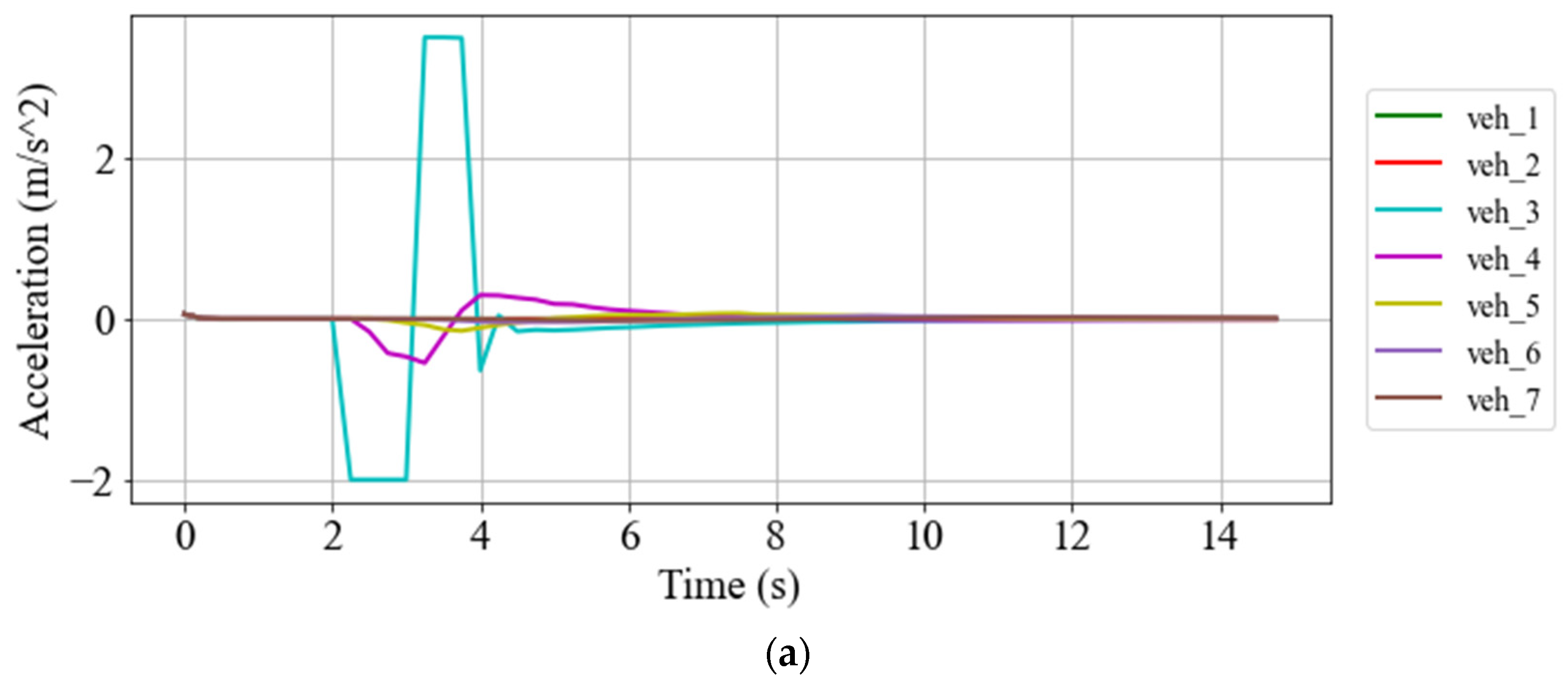
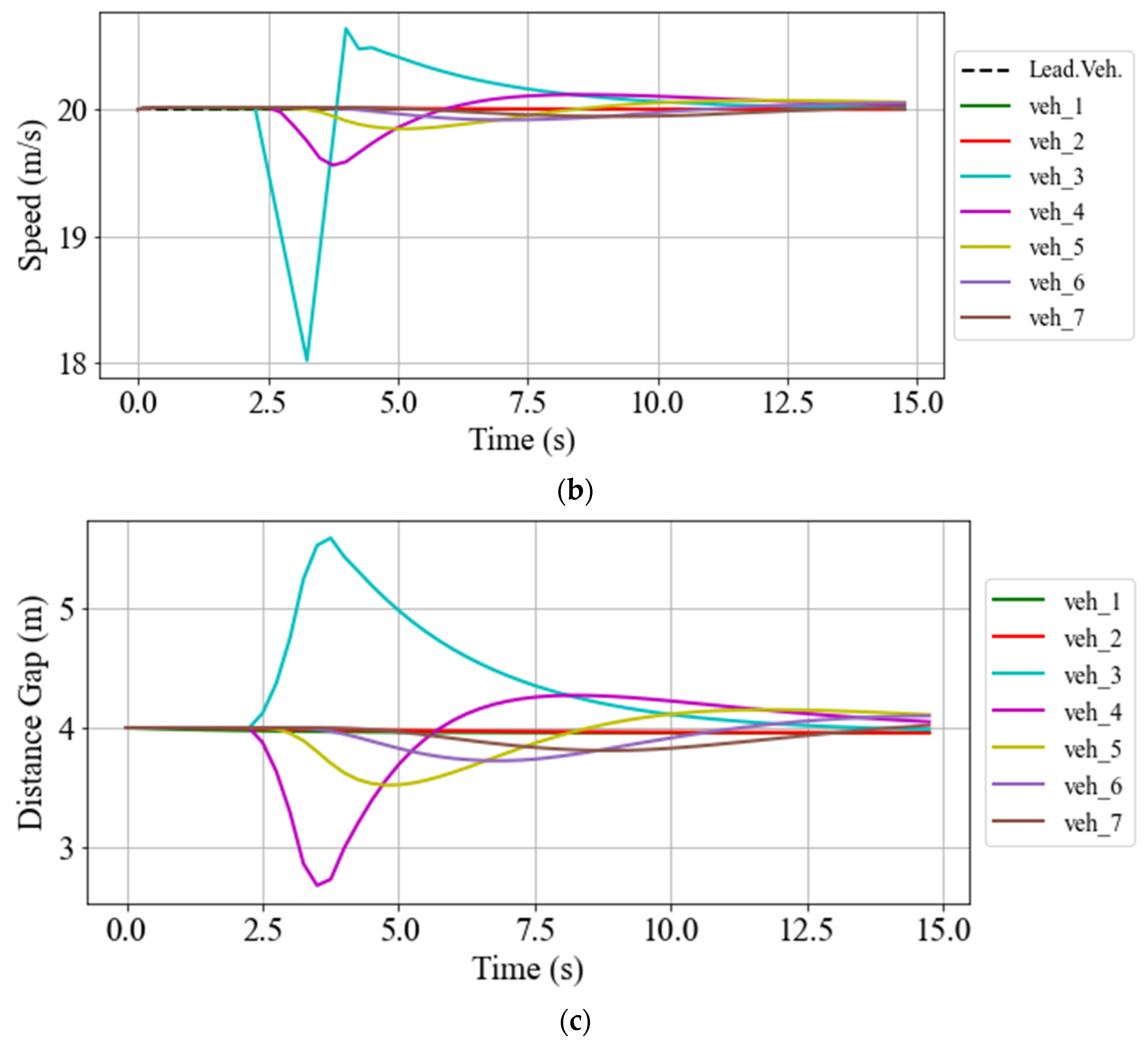
5.2.1. Gap-Closing/Opening

To investigate the performance of the proposed DDPG controller in the case of the gap-closing/opening scenario, the ego-vehicle is located more than 70 m away from the last platoon’s vehicle. The ego-vehicle aims to join the platoon in the shortest possible time. The acceleration, speed, and distance gap of the ego-vehicle compared to its predecessor are illustrated in Figure 4.
Figure 4a shows that the ego-vehicle takes its maximum allowed acceleration at the beginning of the gap-closing manoeuvre to decrease its distance gap from its predecessor, which is the primary goal reflected in the reward function. However, this acceleration leads to high-speed values, and, therefore, the vehicle needs to brake once the space gap is considerably reduced. It is worth noting that, by the deployment of the relative time gap (RTG) in the reward function defined in (12), once the distance gap of the ego-vehicle decreases, its speed also asymptotically approaches the platoon speed (Figure 4b), and the acceleration becomes zero. Figure 4c shows that, after 15 s, the distance-gap setpoint is reached. This speed-change policy of the proposed control algorithm in the gap-closing manoeuvre helps the ego-vehicle to conduct gap-closing manoeuvres in a shorter time without raising any risk of collision.
Additionally, as can be seen in Figure 4c, at the time of 19 s, a gap-opening manoeuvre is triggered by increasing the distance-gap set point of the ego-vehicle from 4 m to 12 m . Consequently, the ego-vehicle decelerates to increase its distance gap or, equivalently, decreases the induced gap error resulting from the new gap set-point. Since this leads to a speed reduction, further acceleration is required, allowing the ego-vehicle to reach the leading vehicle’s speed again while maintaining a new inter-vehicle distance gap. Such changes in vehicle speed and acceleration, depicted in Figure 4, note that, since the reward function is defined in such a way that reduces the required time for the gap opening manoeuvre, the ego-vehicle takes the possible deceleration value to reduce the gap error in a shorter time. Finally, after seven seconds, the ego-vehicle reaches its new equilibrium point with a distance gap of 12 m . Therefore, the acceleration is zero afterward, and its speed follows the speed of the leading vehicle.

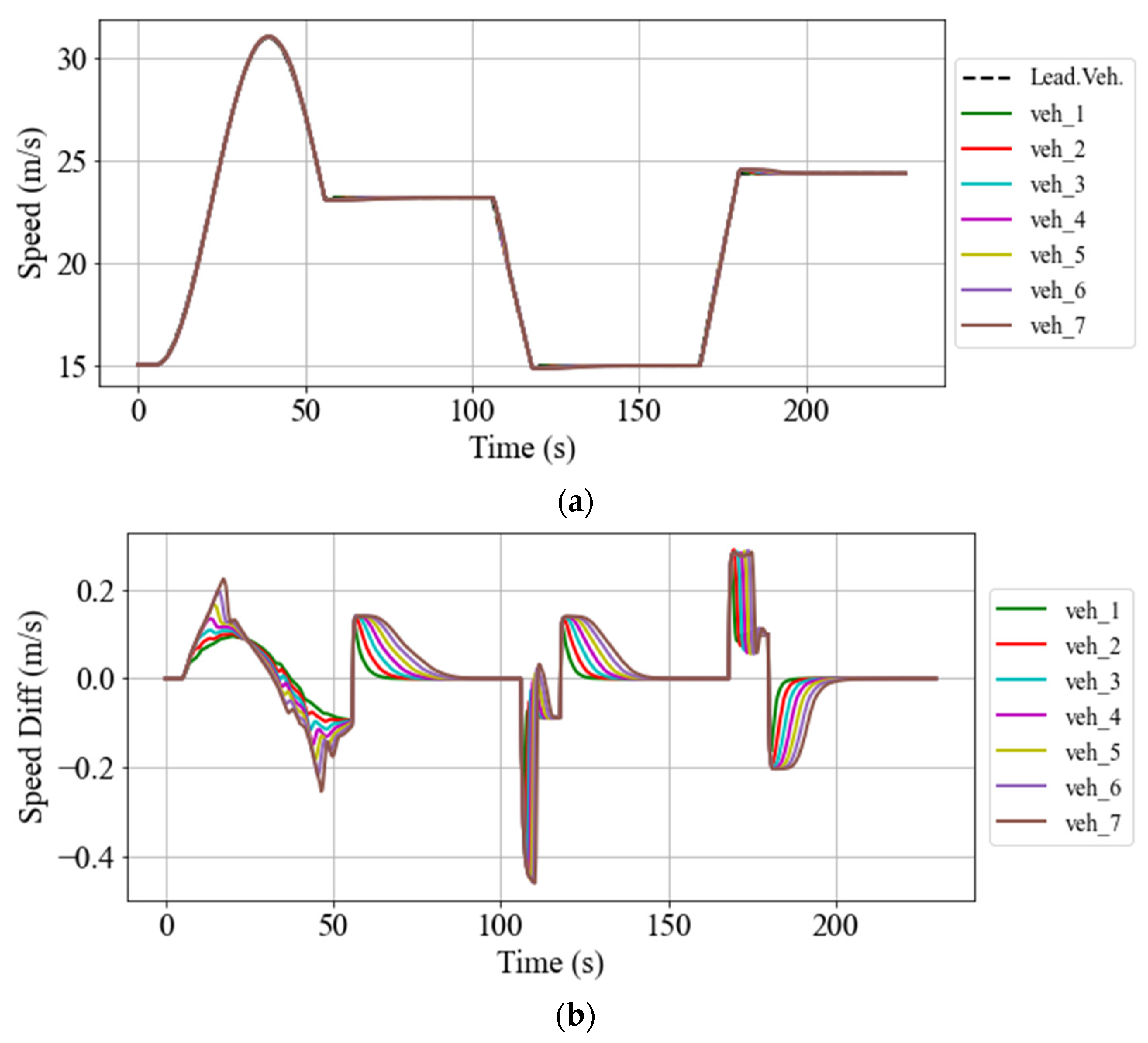
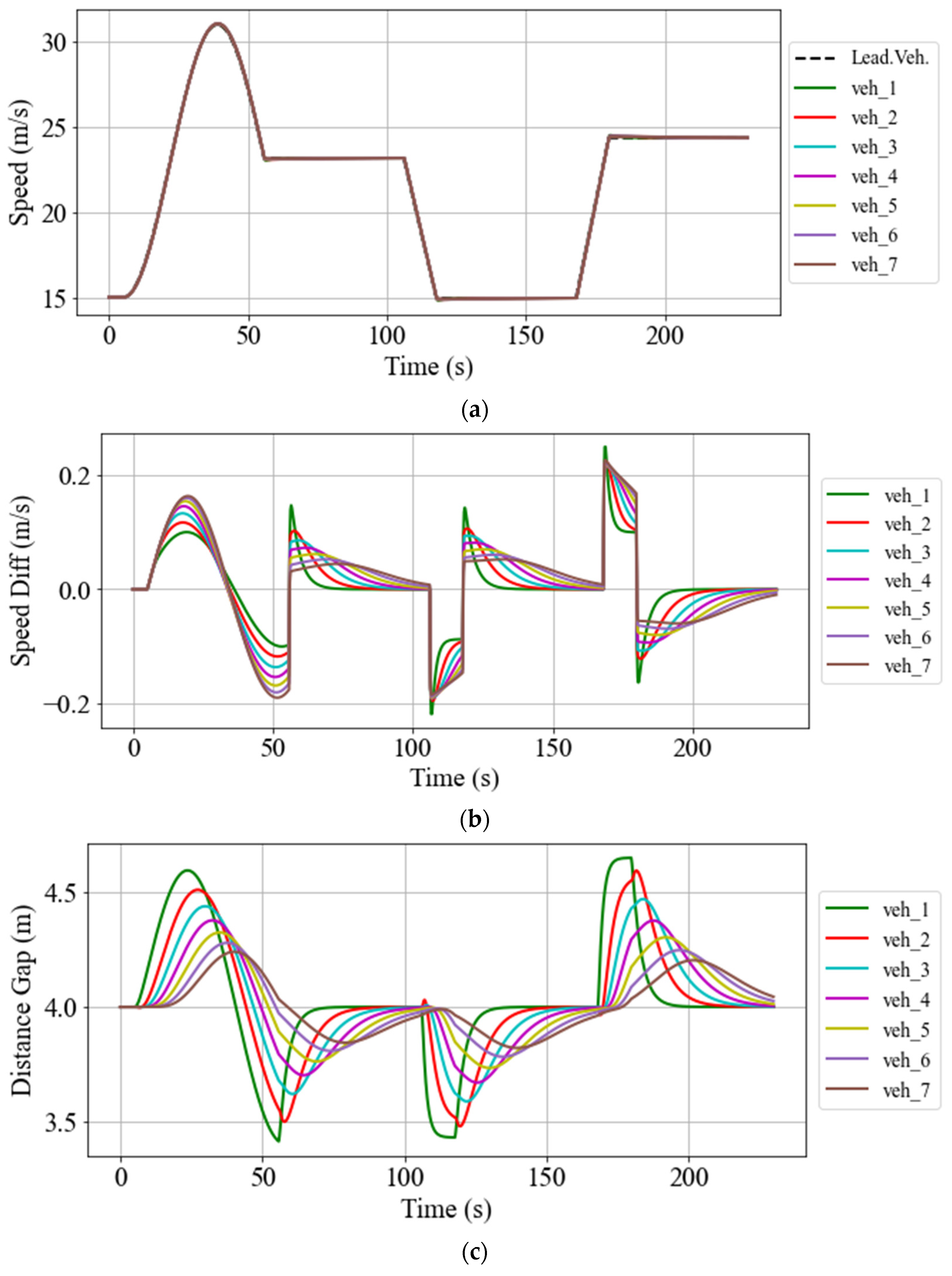
5.2.2. Speed and Space Gap Control

This section evaluates the performance of the developed DDPG algorithm in the behaviour of the platoon vehicles. To this end, a specific speed trajectory of the leading vehicle to be followed by the platoon vehicles is considered (see Figure 5a). It is worth mentioning that, in order to evaluate the performance of the DDPG-based platoon system in speed-tracking mode under a challenging situation, a relatively drastic speed profile for the leading vehicle is considered. However, we are aware that this might constitute an infeasible behaviour in a realistic situation for the required acceleration and induced jerk on the leading vehicle. At the initial time, the platoon system is at its steady-state mode with a speed of 15 m / s and a space-gap of 4 m between two consecutive vehicles. Then, the leading vehicle starts to change its speed by following the predefined speed trajectory, as illustrated in Figure 5a. This figure shows how fast the platoon vehicles follow the speed profile of the leading vehicle with considerably lower errors.
The speed differences between the leading vehicle and each following vehicle are demonstrated in Figure 5b. Such low-value speed errors highlight the superiority of the proposed controller in tracking the leading vehicle’s speed. Comparing Figure 5b with Figure 5a shows the fact that the speed difference is high only once there are abrupt changes in the leading vehicle’s speed. After those abrupt changes, the controller matches the speeds in a relatively short time. In addition to the speed-tracking, Figure 5c demonstrates that the space gap between the vehicles is well maintained, and the maximum distance-gap error between two consecutive vehicles is less than 40 cm . In addition, Figure 5c indicates that, once the speed of the leading vehicle remains constant, e.g., between 60 and 110 s, the distance gaps between the vehicles converge to the predefined value with relatively low errors. This finding depicts the capability of this controller in maintaining a constant inter-vehicle gap, even during the speed change manoeuvres of the platoon leader.
In order to evaluate passenger comfort, the acceleration and jerk of all the following vehicles for the manoeuvres shown in Figure 5 are also illustrated in Figure 6a,b, respectively. The acceleration values for all the vehicles fall between the desired values and, as we might expect, they change abruptly when required due to abrupt changes in the speed of the leading vehicle. Even with such abrupt changes in acceleration, the jerk value during all the manoeuvres for all the following vehicles remains under the maximum value defined in the reward function in Equation (13), again demonstrating an acceptable performance of the DDPG algorithm regarding passenger comfort. Moreover, the maximum jerks in Figure 6b occur when there is a drastic change in the leading vehicle’s speed profile. This implies that the occurrence of a jerk by these values is inevitable if we aim to have perfect speed-tracking in the aforementioned platooning.

5.2.3. String Stability Assessment

As mentioned earlier, string stability is one of the prominent aspects of a platoon system; and, thus, fulfilment of this property in a platoon control system ensures that any perturbation of the velocity or position of the leading vehicle will not result in amplified fluctuations of the following vehicles’ velocity and position [38].
To evaluate the string stability of the developed DDPG-based control, a deceleration of −2 m / s 2 at the time of 2 s is applied to the third vehicle for 1 s. The consequences of this perturbation on the following vehicles are illustrated in Figure 7. The results shown in Figure 7a reveal the fact that, once the perturbation signal is released from the third vehicle, it takes the maximum possible acceleration (3.5 m / s 2 ) to reach the leading vehicle’s speed and minimize its distance-gap error from its preceding vehicle. It is clear that the effect of the induced shock is damped on the vehicles following the third vehicle, and they encounter less variation in their speed (Figure 7b) and the inter-vehicle distance gap (Figure 7c). The mitigated fluctuations in the following vehicles indicate the stability of the platoon under the developed control algorithm. Figure 7b,c indicates that, for the platoon vehicles, it takes about 10 s after the release of the disruption to go back to their steady-state situations.

5.2.4. Comparison Between the Proposed DDPG Method and CACC

In order to highlight the superiority of the proposed approach compared to the traditional CACC method, a CACC method is also employed to control the longitudinal behaviour of each vehicle in a platoon system composed of the same number of vehicles as controlled by the proposed DDPG. Furthermore, the same speed trajectory of the leading vehicle, the same number of vehicles, and a similar space gap set-point are considered to provide the same setup for the CACC platoon system as the DDPG one.
A typical CACC similar to [39,40] is employed in this subsection. Thus, v i , k , the required actual speed of vehicle i at time step k , is defined as:
v i , k = v i , k 1 + Δ T ( K 1 e i , k + K 2 Δ v ( i 1 , i ) , k + K 3 e ( 0 , i ) , k + K 4 Δ v ( 0 , i ) , k )
where Δ v ( i 1 , i ) , k = v i 1 , k v i , k , Δ v ( 0 , i ) , k = v 0 , k v i , k . Moreover, in (15), e ( 0 , i ) , k is defined as
e ( 0 , i ) , k = d ( 0 , i ) , k i ( L d d )
where d ( 0 , i ) , k denotes the actual longitudinal distance between the leading vehicle and vehicle i at time step k . Additionally, the values of K 1 to K 4 in (15) are given in Table 2.
The results of the CACC implementation as a main controller in the aforementioned vehicular platoon are demonstrated in Figure 8. Regarding Figure 8, it can be seen that the required time for the inter-vehicle distance-gap convergence in the CACC platoon system is much higher than in the DDPG platoon system. However, in the CACC platoon system, the inter-vehicle distance gap is expected to converge ultimately to zero (if there is enough time), while, in the DDPG platoon system, there is a minimum gap error between the vehicles. In the case of the speed convergence of the following vehicles in the CACC platoon system, the required time for reducing the speed gap between the vehicles is also much higher than in its DDPG counterpart, which shows the superiority of the proposed method compared to the CACC platoon system. In addition, Figure 8c shows much higher gap errors compared to the DDPG case (Figure 5c).
To further compare the performance of the proposed DDPG algorithm with the mentioned CACC method, four key performance indicators (KPI) are considered: T D G _ e r r o r = i = 1 N k = 1 T | e i , k | (total absolute distance-gap error of all vehicles), T s p e e d _ d i f f = i = 1 N k = 1 T | Δ v ( 0 , i ) , k | (total absolute speed difference of all vehicles related to the platoon leading vehicle), T J e r k = i = 1 N k = 1 T | J e r k i , k | (total absolute jerk of all vehicles related to the platoon leading vehicle), and Max_gap_error (maximum inter-vehicle distance-gap error among all the platoon vehicles). It should be noted that N and T in all of the aforementioned criteria denote the number of following vehicles in a vehicle platoon and the total time elapsed during the speed trajectory manoeuvre, respectively. The results of this comparison are depicted in Table 3. According to Table 3, the proposed DDPG algorithm has better performance as far as T D G _ e r r o r , T s p e e d _ d i f f , and Max_gap_error are concerned; however, in the case of the jerk criterion, the performance of CACC is better than the DDPG algorithm.

6. Conclusions

In this work, a novel car-following strategy for controlling CAVs in a vehicular platoon system based on a machine learning approach is designed and implemented. The main contribution of this work is proposing a single but multi-task controller using a DDPG algorithm. The developed methodology encompasses three major control aspects of a platoon system, including space gap and speed control, and gap-closing and gap-opening manoeuvres. To this end, in the reward function of the DDPG algorithm, we introduced and deployed an effective inter-vehicle distance and relative time gap that allows the mentioned control algorithm to also perform the gap-closing and gap-opening manoeuvres.
The performance of the developed DRL algorithm is evaluated with an eight-vehicle platoon using different scenarios in SUMO. The simulation results show that the gap-closing and gap-opening manoeuvres are performed smoothly in a short time. In addition, the platoon vehicles follow the speed profile of the leading vehicle with negligible speed and gap errors. In the end, by imposing a speed perturbation on one of the platoon vehicles, the string stability of the proposed platoon controller is showcased, and the proposed platoon control system is stable under the speed perturbations. In future works, we will extend the algorithm for vehicular flocking in lane-free environments, where the lateral space gap of the vehicles must also be taken into account.
Another criterion that should be considered during the creation of a vehicular platoon system is the robustness of the platoon controller in terms of unknown data falsification attacks on driving commands; hence, this required aspect should also be considered in the definition of the proposed DDPG reward functions. Therefore, in future work, we aim to design a DRL-based platoon controller that also regards the aforementioned requirement.

Author Contributions

The authors confirm the contributions to the paper as follows. Study conception: M.B. and M.R.-S.; methodology development: M.B. and M.R.-S.; implementation and simulation: M.B.; analysis and interpretation of results: M.B., M.R.-S. and K.B.; draft manuscript preparation: M.B., M.R.-S. and K.B.; All authors have read and agreed to the published version of the manuscript.

Funding

This work at the Technical University of Munich is based on the project “Simulation and organization of future lane-free traffic”, funded by the German research foundation (DFG) under the project number BO 5959/1-1.

Institutional Review Board Statement

Not applicable.

Informed Consent Statement

Not applicable.

Conflicts of Interest

The funders had no role in the design of the study; in the collection, analyses, or interpretation of the data; in the writing of the manuscript; or in the decision to publish the results.

References

  1. Zhang, J.; Wang, F.Y.; Wang, K.; Lin, W.H.; Xu, X.; Chen, C. Data-driven intelligent transportation systems: A survey. IEEE Trans. Intell. Transp. Syst. 2011, 12, 1624–1639. [Google Scholar] [CrossRef]
  2. Horowitz, R.; Varaiya, P. Control design of an automated highway system. Proc. IEEE 2000, 88, 913–925. [Google Scholar] [CrossRef]
  3. Rostami-Shahrbabaki, M.; Haghbayan, S.A.; Akbarzadeh, M.; Bogenberger, K. On the Technical Feasibility of Vehicle to Vehicle Charging for Electric Vehicles via Platooning on Freeways. In Proceedings of the 2022 European Control Conference (ECC), Bucharest, Romania, 13–16 June 2022; pp. 530–537. [Google Scholar] [CrossRef]
  4. Johansson, I.; Jin, J.; Ma, X.; Pettersson, H. Look-ahead speed planning for heavy-duty vehicle platoons using traffic information. Transp. Res. Procedia 2017, 22, 561–569. [Google Scholar] [CrossRef]
  5. Wang, M.; van Maarseveen, S.; Happee, R.; Tool, O.; van Arem, B. Benefits and Risks of Truck Platooning on Freeway Operations Near Entrance Ramp. Transp. Res. Rec. 2019, 2673, 588–602. [Google Scholar] [CrossRef]
  6. VanderWerf, J.; Shladover, S.; Kourjanskaia, N.; Miller, M.; Krishnan, H. Modeling Effects of Driver Control Assistance Systems on Traffic. Transp. Res. Rec. 2001, 1748, 167–174. [Google Scholar] [CrossRef]
  7. Chehardoli, H.; Homaeinezhad, M.R. Third-order leader-following consensus protocol of traffic flow formed by cooperative vehicular platoons by considering time delay: Constant spacing strategy. Proc. Inst. Mech. Eng. Part I J. Syst. Control. Eng. 2018, 232, 285–298. [Google Scholar] [CrossRef]
  8. Gao, F.; Li, S.E.; Zheng, Y.; Kum, D. Robust control of heterogeneous vehicular platoon with uncertain dynamics and communication delay. IET Intell. Transp. Syst. 2016, 10, 503–513. [Google Scholar] [CrossRef] [Green Version]
  9. Fardad, M.; Lin, F.; Jovanović, M.R. Sparsity-promoting optimal control for a class of distributed systems. In Proceedings of the 2011 American Control Conference, San Francisco, CA, USA, 29 June–1 July 2011; pp. 2050–2055. [Google Scholar] [CrossRef] [Green Version]
  10. Dunbar, W.B.; Caveney, D.S. Distributed receding horizon control of vehicle platoons: Stability and string stability. IEEE Trans. Automat. Contr. 2012, 57, 620–633. [Google Scholar] [CrossRef]
  11. Wu, Y.; Li, S.E.; Zheng, Y.; Hedrick, J.K. Distributed sliding mode control for multi-vehicle systems with positive definite topologies. In Proceedings of the 2016 IEEE 55th Conference on Decision and Control (CDC), Las Vegas, NV, USA, 12–14 December 2016; pp. 5213–5219. [Google Scholar] [CrossRef]
  12. Aradi, S. Survey of Deep Reinforcement Learning for Motion Planning of Autonomous Vehicles. IEEE Trans. Intell. Transp. Syst. 2022, 23, 740–759. [Google Scholar] [CrossRef]
  13. Lin, Y.; McPhee, J.; Azad, N.L. Comparison of Deep Reinforcement Learning and Model Predictive Control for Adaptive Cruise Control. IEEE Trans. Intell. Veh. 2021, 6, 221–231. [Google Scholar] [CrossRef]
  14. Zhou, Y.; Fu, R.; Wang, C. Learning the Car-following Behavior of Drivers Using Maximum Entropy Deep Inverse Reinforcement Learning. J. Adv. Transp. 2020, 2020, 4752651. [Google Scholar] [CrossRef]
  15. Mnih, V.; Kavukcuoglu, K.; Silver, D.; Rusu, A.A.; Veness, J.; Bellemare, M.G.; Graves, A.; Riedmiller, M.; Fidjeland, A.K.; Ostrovski, G.; et al. Human-level control through deep reinforcement learning. Nature 2015, 518, 529–533. [Google Scholar] [CrossRef] [PubMed]
  16. Lillicrap, T.P.; Hunt, J.J.; Pritzel, A.; Heess, N.; Erez, T.; Tassa, Y.; Silver, D.; Wierstra, D. Continuous control with deep reinforcement learning. arXiv 2015, arXiv:1509.02971. [Google Scholar]
  17. Lopez, P.A.; Behrisch, M.; Bieker-Walz, L.; Erdmann, J.; Flotterod, Y.P.; Hilbrich, R.; Lucken, L.; Rummel, J.; Wagner, P.; Wiebner, E. Microscopic Traffic Simulation using SUMO. In Proceedings of the 2018 21st International Conference on Intelligent Transportation Systems (ITSC), Maui, HI, USA, 4–7 November 2018; pp. 2575–2582. [Google Scholar] [CrossRef] [Green Version]
  18. Haydari, A.; Yilmaz, Y. Deep Reinforcement Learning for Intelligent Transportation Systems: A Survey. IEEE Trans. Intell. Transp. Syst. 2022, 23, 11–32. [Google Scholar] [CrossRef]
  19. Zhu, M.; Wang, Y.; Pu, Z.; Hu, J.; Wang, X.; Ke, R. Safe, efficient, and comfortable velocity control based on reinforcement learning for autonomous driving. Transp. Res. Part C Emerg. Technol. 2020, 117, 102662. [Google Scholar] [CrossRef]
  20. Li, M.; Li, Z.; Xu, C.; Liu, T. Deep Reinforcement Learning-Based Vehicle Driving Strategy to Reduce Crash Risks in Traffic Oscillations. Transp. Res. Rec. 2020, 2674, 42–54. [Google Scholar] [CrossRef]
  21. Zhu, M.; Wang, X.; Wang, Y. Human-like autonomous car-following model with deep reinforcement learning. Transp. Res. Part C Emerg. Technol. 2018, 97, 348–368. [Google Scholar] [CrossRef]
  22. Zhou, M.; Yu, Y.; Qu, X. Development of an Efficient Driving Strategy for Connected and Automated Vehicles at Signalized Intersections: A Reinforcement Learning Approach. IEEE Trans. Intell. Transp. Syst. 2020, 21, 433–443. [Google Scholar] [CrossRef]
  23. Isele, D.; Rahimi, R.; Cosgun, A.; Subramanian, K.; Fujimura, K. Navigating Occluded Intersections with Autonomous Vehicles Using Deep Reinforcement Learning. In Proceedings of the 2018 IEEE International Conference on Robotics and Automation (ICRA), Brisbane, QLD, Australia, 21–25 May 2018. [Google Scholar]
  24. Kim, M.; Lee, S.; Lim, J.; Choi, J.; Kang, S.G. Unexpected collision avoidance driving strategy using deep reinforcement learning. IEEE Access 2020, 8, 17243–17252. [Google Scholar] [CrossRef]
  25. Xiao, S.; Ge, X.; Han, Q.L.; Zhang, Y. Secure Distributed Adaptive Platooning Control of Automated Vehicles Over Vehicular Ad-Hoc Networks Under Denial-of-Service Attacks. IEEE Trans. Cybern. 2021, 52, 12003–12015. [Google Scholar] [CrossRef]
  26. Xiao, S.; Ge, X.; Han, Q.L.; Zhang, Y. Secure and collision-free multi-platoon control of automated vehicles under data falsification attacks. Automatica 2022, 145, 110531. [Google Scholar] [CrossRef]
  27. Kiran, B.R.; Sobh, I.; Talpaert, V.; Mannion, P.; Sallab, A.A.A.; Yogamani, S.; Perez, P. Deep Reinforcement Learning for Autonomous Driving: A Survey. IEEE Trans. Intell. Transp. Syst. 2022, 23, 4909–4926. [Google Scholar] [CrossRef]
  28. Wei, S.; Zou, Y.; Zhang, T.; Zhang, X.; Wang, W. Design and Experimental Validation of a Cooperative Adaptive Cruise Control System Based on Supervised Reinforcement Learning. Appl. Sci. 2018, 8, 1014. [Google Scholar] [CrossRef] [Green Version]
  29. Yan, R.; Jiang, R.; Jia, B.; Huang, J.; Yang, D. Hybrid Car-Following Strategy Based on Deep Deterministic Policy Gradient and Cooperative Adaptive Cruise Control. IEEE Trans. Autom. Sci. Eng. 2021, 19, 2816–2824. [Google Scholar] [CrossRef]
  30. Berahman, M.; Rostmai-Shahrbabaki, M.; Bogenberger, K. Driving Strategy for Vehicles in Lane-Free Traffic Environment Based on Deep Deterministic Policy Gradient and Artificial Forces. IFAC-PapersOnLine 2022, 55, 14–21. [Google Scholar] [CrossRef]
  31. Luo, X.; Chen, T.; Li, M.; Li, S. Platoon Control of Automatic Vehicles Based on Deep Deterministic Policy Gradient. In Proceedings of the 2021 40th Chinese Control Conference (CCC), Shanghai, China, 26–28 July 2021; Volume 2021, pp. 6154–6159. [Google Scholar] [CrossRef]
  32. Semsar-Kazerooni, E.; Verhaegh, J.; Ploeg, J.; Alirezaei, M. Cooperative adaptive cruise control: An artificial potential field approach. In Proceedings of the 2016 IEEE Intelligent Vehicles Symposium (IV), Gothenburg, Sweden, 19–22 June 2016. [Google Scholar]
  33. Li, S.E.; Zheng, Y.; Li, K.; Wang, J. An overview of vehicular platoon control under the four-component framework. IEEE Intell. Veh. Symp. Proc. 2015, 2015, 286–291. [Google Scholar] [CrossRef]
  34. Swaroop, D.; Hedrick, J.K.; Chien, C.C.; Ioannou, P. A Comparision of Spacing and Headway Control Laws for Automatically Controlled Vehicles1. Veh. Syst. Dyn. 2007, 23, 597–625. [Google Scholar] [CrossRef]
  35. Arulkumaran, K.; Deisenroth, M.P.; Brundage, M.; Bharath, A.A. Deep reinforcement learning: A brief survey. IEEE Signal Process. Mag. 2017, 34, 26–38. [Google Scholar] [CrossRef] [Green Version]
  36. Wegener, A.; Piórkowski, M.; Raya, M.; Hellbrück, H.; Fischer, S.; Hubaux, J.P. TraCI: An interface for coupling road traffic and network simulators. In Proceedings of the 11th Communications and Networking Simulation Symposium, Ottawa, ON, Canada, 14–17 April 2008; pp. 155–163. [Google Scholar] [CrossRef]
  37. Paszke, A.; Gross, S.; Chintala, S.; Chanan, G.; Yang, E.; DeVito, Z.; Lin, Z.; Desmaison, A.; Antiga, L.; Lerer, A. Automatic differentiation in PyTorch. In Proceedings of the NIPS 2017 Autodiff Workshop: The Future of Gradient-based Machine Learning Software and Techniques, Long Beach, CA, USA, 9 December 2017. [Google Scholar]
  38. Xiao, L.; Gao, F. Practical string stability of platoon of adaptive cruise control vehicles. IEEE Trans. Intell. Transp. Syst. 2011, 12, 1184–1194. [Google Scholar] [CrossRef]
  39. Li, S.E.; Zheng, Y.; Li, K.; Wu, Y.; Hedrick, J.K.; Gao, F.; Zhang, H. Dynamical Modeling and Distributed Control of Connected and Automated Vehicles: Challenges and Opportunities. IEEE Intell. Transp. Syst. Mag. 2017, 9, 46–58. [Google Scholar] [CrossRef]
  40. Shaout, A.K.; Jarrah, M.A. Cruise control technology review. Comput. Electr. Eng. 1997, 23, 259–271. [Google Scholar] [CrossRef]
Figure 1. Configuration of a vehicle platoon with a constant distance gap.
Futuretransp 02 00057 g001
Figure 2. Actor–critic neural network structures for DDPG.
Futuretransp 02 00057 g002
Figure 3. Average accumulated reward in the total training phase.
Futuretransp 02 00057 g003
Figure 4. Acceleration (a), speed (b), and distance-gap (c) variations in the ego-vehicle during gap-closing and gap-opening manoeuvres.
Futuretransp 02 00057 g004aFuturetransp 02 00057 g004b
Figure 5. Variations in speed (a), speed difference (b), and distance gap (c) of participant vehicles in the platoon system with respect to speed trajectory followed by the leading vehicle.
Futuretransp 02 00057 g005aFuturetransp 02 00057 g005b
Figure 6. Variations in acceleration (a) and jerk (b) of participant vehicles in the platoon system with respect to speed trajectory followed by the leading vehicle.
Futuretransp 02 00057 g006aFuturetransp 02 00057 g006b
Figure 7. Acceleration (a), speed (b), and distance-gap (c) variations in platoon vehicles relative to the drastic braking of the third vehicle.
Futuretransp 02 00057 g007aFuturetransp 02 00057 g007b
Figure 8. Variations in speed (a), speed difference (b), and distance gap (c) of participant vehicles in the CACC platoon system with respect to speed trajectory followed by the leading vehicle.
Futuretransp 02 00057 g008
Table 1. Simulation settings and DDPG hyperparameter.
ParameterValueParameterValue
Actor & Critic learning rates10−4 (10−2)Highway length (width)5 km (3.2 m)
γ 0.99Vehicle length (width)3.2 m (1.6 m)
τ0.005 Δ t 0.25 s
Batch size256Initial vehicle speed[10, 50] m/s
Experience replay buffer size1,000,000 R T G m a x   ( R T G m i n )4 s (2 s)
Maximum acceleration
(deceleration)
3.5 (−3.5) m/s2dd4 m
α 0.1Maximum simulation step at each episode100
Table 2. Parameters of CACC.
Parameter K 1 K 2 K 3 K 4
Value0.150.010.020.9
Table 3. Result comparison between CACC and DDPG in case of speed and space gap control.
KPICACCDDPG
T D G _ e r r o r 25,846 m25,627 m
T s p e e d _ d i f f 369.31 m/s334.13 m/s
T J e r k 171.08 m/s2226.62 m/s2
Max_gap_error65 cm40 cm
Publisher’s Note: MDPI stays neutral with regard to jurisdictional claims in published maps and institutional affiliations.

