Article

An Experimental Investigation on the Pool Boiling Heat Transfer of R-134a on Microporous Cu-MWCNT Composite Surfaces

1
Department of Mechanical Engineering, Pimpri Chinchwad College of Engineering, Pune 411044, India
2
Department of Mechanical Engineering, National Institute of Technology Agartala, Agartala 799046, India
3
Department of Mechanical Engineering, Birla Institute of Technology and Science Pilani, Pilani 333031, India
*
Author to whom correspondence should be addressed.
Thermo 2024, 4(1), 16-28; https://doi.org/10.3390/thermo4010002
Submission received: 15 December 2023 / Revised: 6 January 2024 / Accepted: 15 January 2024 / Published: 17 January 2024

Abstract

:
Multiwalled carbon nanotubes (MWCNTs) exhibit outstanding physical properties, including high thermal conductivity, excellent mechanical strength, and low electrical resistivity, which make them suitable candidates for a variety of applications. The work presented in this paper focuses on the pool boiling performance of refrigerant R-134a on microporous Cu-MWCNT composite surface layers. A two-stage electrodeposition technique was used to fabricate Cu-MWCNT composite coatings. In order to achieve variation in the surface properties of the Cu-MWCNT composite surface layer, electrodeposition was carried out at various bath temperatures (25 °C, 30 °C, 35 °C, and 40 °C). All surfaces coated with the Cu-MWCNT composite demonstrated superior boiling performance compared to the uncoated surface. Heat transfer coefficient (HTC) values for Cu-MWCNT composite surface layers, prepared at bath temperatures of 25 °C, 30 °C, 35 °C, and 40 °C, exhibited improvements of up to 1.75, 1.88, 2.06, and 2.22, respectively, in comparison to the plain Cu surface.

1. Introduction

In the past few decades, awareness about the importance of reducing energy use and protecting the environment has increased in response to the greenhouse effect generated by the burning of fossil fuels [1,2]. The Intergovernmental Panel on Climate Change’s (IPCC) sixth assessment report emphasizes the urgency of taking action to reduce greenhouse gas emissions and limit global warming [3]. Greenhouse warming can be reduced by improving the efficiency of energy conversion devices. To achieve this objective, the performance of heat transfer in air-conditioning and refrigeration equipment has to be increased. Because of the high heat removal capacity, boiling heat transfer (BHT) has been used in several thermal management systems [4]. Recently, BHT has been proposed as a solution for systems with extremely high heat flux in a very compact volume. Therefore, boiling heat dissipation is extensively employed in various industrial sectors, including batteries for electric vehicles, electronic gadgets, boilers, nuclear power plants, and reactors [5].
In recent years, there has been a significant amount of research on methods for improving passive pool BHT with microscale surface cavities, porous coatings, and the growth of dendrite structures [6]. Active cavities are those cavities containing trapped non-condensable gases that usually generate bubbles [7]. A microporous coating is one of the best ways to improve pool BHT because it has more active cavities on the heating surface [8]. Microporous surfaces have been extensively researched in the literature. Anderson et al. [9] fabricated a microporous surface by vapor blasting on the Cu test surface, yielding a 170% increase in critical heat flux (CHF) with FC-87. Bergles et al. [10] used a proprietary method to fabricate porous surfaces on the bronze substrate, yielding 250% enhancement in heat transfer coefficient (HTC) with water and up to 8 times enhancement with refrigerants. Sugiyama et al. [11] examined the pool BHT performance of R-114 on various surfaces. They discovered that the augmentation with porous heat transfer surface was only significant at low values of heat flux.
Numerous techniques, such as spray coating [12], RF sputtering [13], electrodeposition [14], PVD [15], e-beam evaporation [16], CVD [17], and dip coating [18], have been used to fabricate microporous coatings. Electrodeposition is preferred over available techniques for the preparation of microporous coatings on metallic heating surfaces because of its simplicity, controllability, and cost-effectiveness [19,20]. Gheitaghy et al. [21] systematically studied nanostructured microporous surfaces fabricated by electrodeposition techniques by varying electrolyte temperatures. Results showed that the HTC of the nanostructured microporous surface was 270% higher than that of the bare copper surface. Gupta et al. [22] prepared Cu-TiO2 nanocomposite coatings by a two-step electrodeposition method. They found a significant augmentation of 185% in HTC and an increase of 86% in CHF compared with the bare copper surface. Protich et al. [23] developed a copper–graphene composite using an electrodeposition technique and reported augmentation of 66% in CHF. Katarkar et al. [19] fabricated microporous Cu-graphene composite coatings and attained a 97% increase in HTC relative to the bare Cu surface. Shakeri et al. [24] created hierarchical pattern heating surfaces using a combination of six-stage electrodeposition and photolithography techniques and achieved an improvement of about 119% in HTC compared to the bare surface. During electrodeposition, the surface roughness and porosity of copper coating can be tailored by varying the process parameters such as temperature, pH, current density, and rate of magnetic stirring [25]. In order to further enhance the pool BHT, the reinforcement of graphene oxide [26], graphene nanoplatelet [19], aluminum oxide [27], and titanium oxide [22] particles into copper matrix coatings have been used. Multiwalled carbon nanotubes (MWCNTs), a member of the carbon group, have extraordinary mechanical, thermal, thermodynamic, and electrochemical properties [28]. This study presents a microporous Cu-MWCNT composite heating surface that synergistically combines the high thermal conductivity of copper with the unique properties of MWCNTs. The reinforcement of MWCNTs into the copper matrix may help in enhancing the pool BHT performance. This advancement could revolutionize fields like electronics cooling, power generation, and thermal management in demanding industrial processes. However, the pool BHT performance on two-stage electro-co-deposited Cu-MWCNT composite coatings with R-134a is not studied yet.
In this research, MWCNT-reinforced Cu matrix (Cu-MWCNT) composite coatings were fabricated by varying bath temperatures (25 °C, 30 °C, 35 °C, and 40 °C) using a two-stage electrodeposition technique, and the pool BHT performance of R-134a on coated surfaces was examined. The effect of bath temperature on surface morphology, elemental composition, roughness, porosity, and wettability of Cu-MWCNT composite coatings was investigated. The microporous Cu-MWCNT composite-coated surfaces are prepared with the aim of reducing the energy loss from thermal systems and demonstrating their suitability for energy-saving applications.

2. Surface Preparation and Characterization

2.1. Materials

Copper sulfate pentahydrate (CuSO4·5H2O) and sulfuric acid (H2SO4) were obtained from Merck Life Science, Bengaluru, India. The MWCNTs (length = 1–10 μm, inner diameter = 2–6 nm, outer diameter = 10–15 nm, and purity = 90%) were received from Sigma-Aldrich, Bengaluru, India.

2.2. Two-Stage Electrodeposition

The copper substrates were ground with 120-, 400-, 800-, 1200-, and 2000-grade waterproof abrasive paper, and subsequently, cleaning was carried out using acetone to remove oil and similar dirt. After that, the copper substrates were washed with deionized (DI) water and dried. The obtained substrate was considered as an uncoated Cu heating surface (surface roughness = 0.08 ± 0.02 µm) and also used to deposit composite coatings in the present work. The Cu-MWCNTs electroplating solution consisted of 100 g/L CuSO4·5H2O, 5–30 g/L H2SO4, 50 mg/L MWCNTs, and 500 mL DI water. The details of the operating conditions employed for the two-stage electrodeposition process are listed in Table 1. The cleaned copper substrate with the dimension of Ø 9.0 mm was employed as a cathode, and a pure copper plate (99.95%) was utilized as an anode. Prior to the deposition process, the plating solution was stirred to disperse the MWCNTs in the plating solution using a magnetic stirrer at 300 rpm for 1 h. After this, ultrasonic oscillation (20 kHz, 500 W) was provided for 45 min to evenly disperse MWCNTs in the electrolyte bath. The pH value of the bath was adjusted to 2 by adding H2SO4. The electrodeposition of Cu-MWCNT composite coatings was carried out at various electrolyte bath temperatures using a two-stage electrodeposition technique, as shown in Figure 1. The higher current density (0.2 A/cm2) was applied in the first stage for 60 s to form a microporous coating, and subsequently, a low current density was used for 0.5 h to provide more strength to the microporous structure. The evaluation of hydrogen bubbles on the surface of the coating was clearly observed during the deposition process.

2.3. Characterization of Cu-MWCNT Composite Coatings

The morphologies and compositions of MWCNT and Cu-MWCNT composite coatings were examined by an FEI-Apreo-S scanning electron microscope with energy-dispersive spectroscopy (SEM/EDS, FEI, Delhi, India). The thicknesses of prepared coatings were gauged using a laser ellipsometer (Sentech, Mumbai, India). The roughness curve for Cu-MWCNT composite coatings was determined by a 2D profilometer (Taylor Habsons, Bengaluru, India). ImageJ software (1.54d) was employed to determine the porosity of the coating surface.

3. Experimental Setup and Procedure

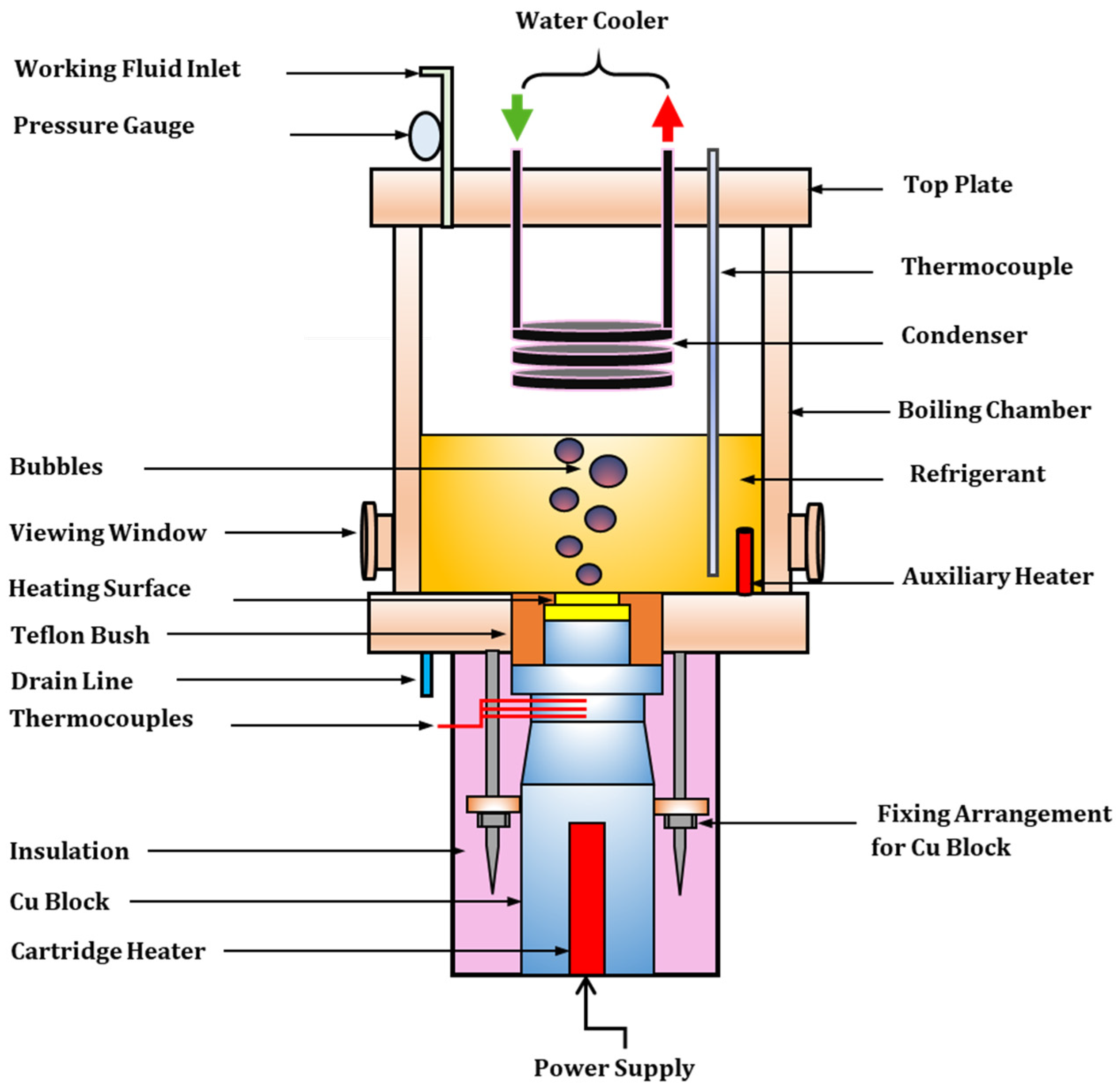
3.1. Pool Boiling Experimental Setup

Figure 2 shows the essential components and apparatus used in the pool boiling experiments. The experimental setup consisted of a condensation unit, thermocouples, an electrical source, a copper block that served as the heater, and a cylindrical boiling vessel. The cylindrical boiling vessel (volume ≈ 4.48 L) was made of steel. It had two circular observation windows on either side, which were covered with Pyrex glass to allow for observation of the internal heating phenomenon. The vessel was sealed with two round steel flanges, one at the top and one at the bottom. A refrigerant injection device was mounted on the upper flange. The condensation coil condenses the evaporated vapor and helps to maintain the boiling vessel at the saturated level. The pressure of the heating vessel was monitored with a pressure gauge. The applied pressure of the saturation fluid was controlled by the electrical pressure limiter and controller, known as the pressure valve, within a specified pressure range. The boiling liquid in the pool was heated to a saturation temperature using a secondary heater. Appropriate exterior insulation made of glass fiber was used on the heating vessel to maintain isothermal conditions. To prevent heat from transferring from the copper blocks to the heating vessel, a Teflon ring was used to seal the joint between the bottom flanges of the heating vessel and the copper block. The cartridge heater was connected to a variac to control the heating power. The copper-heated blocks were placed over the lower portion of the test surface area. Three K-type thermocouples were inserted into the heating element at an angular distance of 120 degrees to monitor the temperature and heat flow of the test surface. To accurately measure the liquid’s saturation temperature, another thermocouple was installed in the liquid.

3.2. Experimental Procedure

Refrigerant R-134a was used to investigate the pool BHT of uncoated copper and coated Cu-MWCNT composite surface layers. The thermophysical fluid properties of R-134a are obtained from Ref. [29]. Acetone was used to rinse the heating boiling chamber before each run of testing. The testing surface was mounted at the lower flange of the heating vessel. After installation, nitrogen gas was introduced into the vessel to check for leaks. Once the unit was confirmed to be leak-proof, R-134a coolant was added to the boiling vessel. The refrigerant R-134a was boiled for two hours using an additional heater to remove any dissolved gases. The pool BHT of R-134a was evaluated at a steady pressure ratio O p e r a t i n g   p r e s s u r e   C r i t i c a l   p r e s s u r e   of 0.102 and an equilibrium temperature of 10 °C. During all the tests, the data points were taken in the order of increasing heat flux ranging from 7 to 60 kW/m2 in the pool of 10 °C. The mass flow rate of the condensing liquid from the water chiller was adjusted for each power input to maintain a constant pressure in the system. The same experimental protocol was followed for each test surface. After each experiment, the test surface and coolant R-134a were removed from the boiling vessel.

4. Data Reduction and Uncertainty Analysis
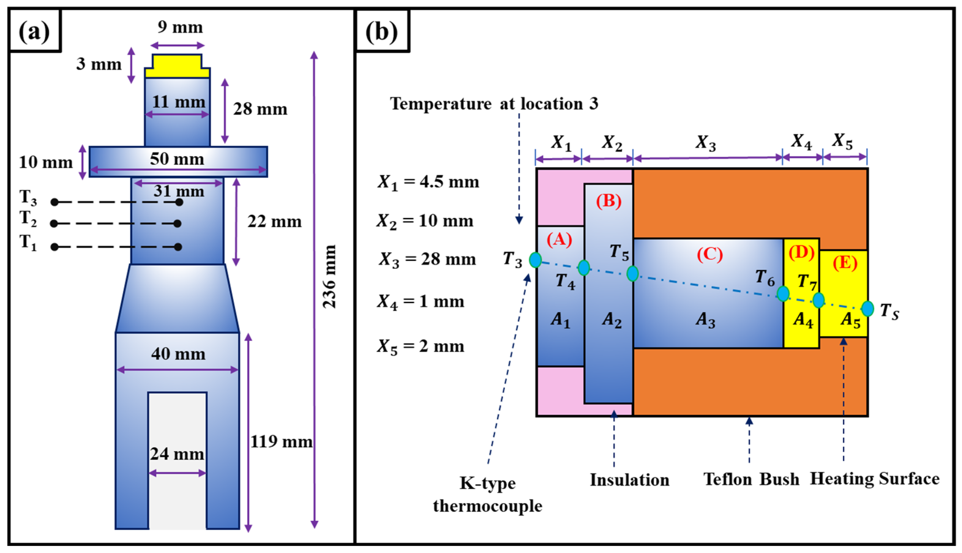
4.1. Data Reduction

The schematic diagram of the heating section to measure the heat fluxes is shown in Figure 3a. In order to minimize heat losses in the radial direction and provision of 1D heat flow, the heating section was insulated with mineral insulation tape, polyethylene foam, and glass wool. To minimize the contact resistance, a thin layer of thermal grease was applied between the heating surface and the copper heating block. The entire assembly is then secured tightly inside a Teflon bush using a nut and bolt locking mechanism. Hence, in the present study, the contact resistance between the heating surface and the copper heating block is assumed to be neglected. The resistance diagram, shown in Figure 3b, was used to calculate the surface temperatures. Please note that Figure 3b is not drawn to scale. The rates of heat transfer (Q) in various sections (A), (B), (C), (D), and (E) were determined using Fourier’s law of heat conduction equation along the axial direction of heating section, represented by Equations (1), (2), (3), (4) and (5), respectively.
Q A = k A A   T 3 T 4 X 1
Q B = k A B   T 4 T 5 X 2
Q C = k A C   T 5 T 6 X 3
Q D = k A D   T 6 T 7 X 4
Q E = k A E   T 7 T S X 5
where k is thermal conductivity, A is the area of the section, and X is the section length.
The surface temperature ( T S ) was determined by Equation (6):
T S = T 3 V I k X 1 A A + X 2 A B + X 3 A C + X 4 A D + X 5 A E
Heat flux ( q ) was determined by Equation (7):
q = Q A E
The BHT coefficient can be obtained by Equation (8):
h = q T s T s a t
where T s a t is the saturation temperature of the working fuid (R-134a).

4.2. Uncertainty Analysis

Uncertainty analysis of the measuring devices and experimental data was performed using the methodology proposed by Schultz and Cole [30].
Mathematically ,   U y = i = 1 n y x i U x i 2 1 2
where U x i is uncertainty associated with x i , and y is the calculated parameter.
The systematic errors for temperature, voltage, length, and current measurements were determined to be ±0.1 °C, ±0.01 V, ±1.0 mm, and ±0.002 A, respectively. The calculated uncertainties for wall superheat (∆T), heat transfer coefficient (h), and heat flux (q) were ±7.8%, ±8.2%, and ±3.2%, respectively.

5. Results and Discussion

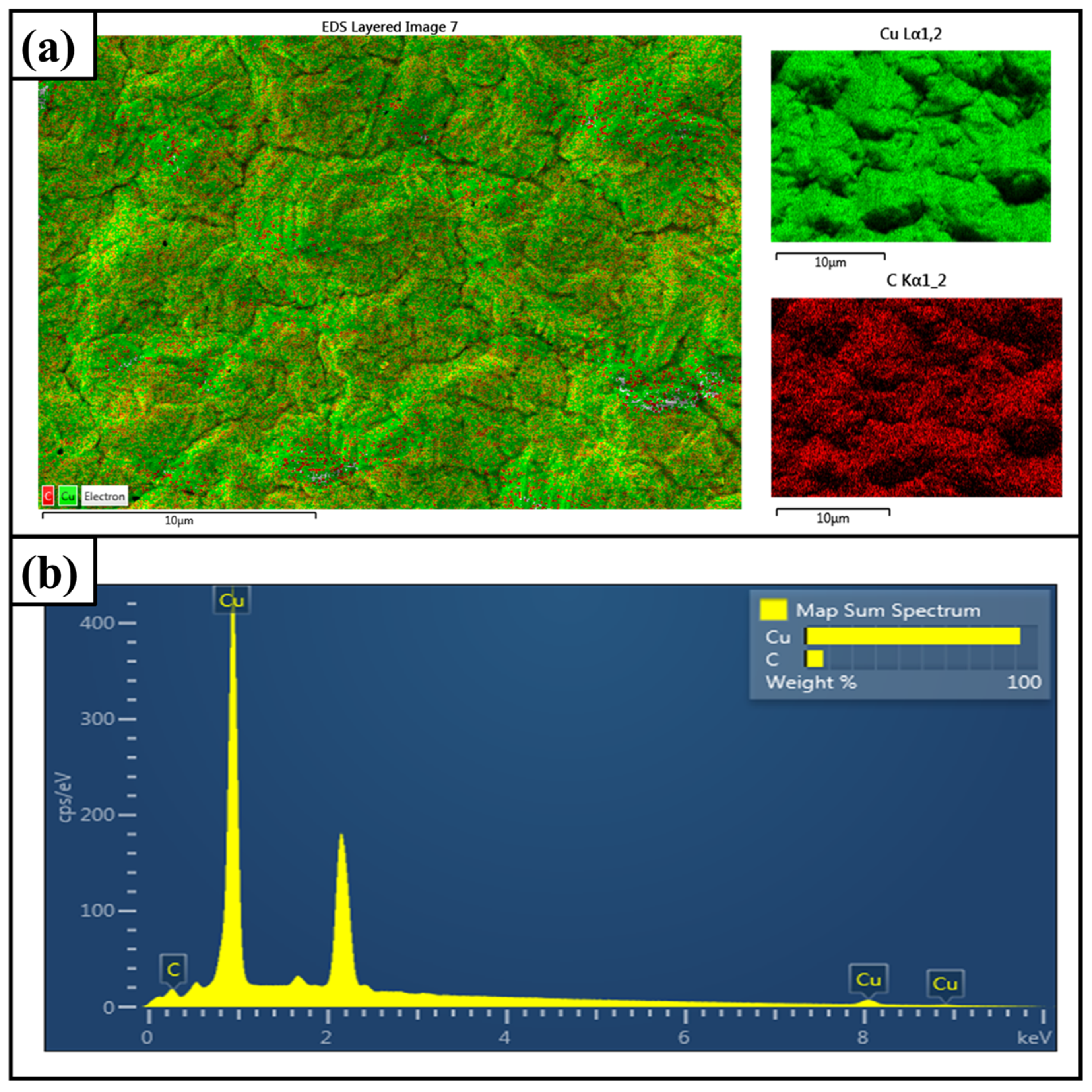
5.1. Surface Characterization of Cu-MWCNT Composite Coatings

The FE-SEM images of the Cu-MWCNT composite surface layers deposited at various bath temperatures are depicted in Figure 4. At low bath temperatures (25 °C and 30 °C), the surface of the Cu-MWCNT composite appears relatively smooth, as seen in Figure 4a–d. With an increase in bath temperature (35 °C and 40 °C), the Cu-MWCNT composite coating grows relatively quickly, resulting in high surface roughness and larger particle size (see Figure 4e–h). The existence of micropores is clearly observed in Figure 4g,h. This is mainly due to the fast crystallization of the composite coating in a high-temperature environment. The EDS element distribution map and corresponding EDS spectrum of Cu-MWCNT composite coating deposited at 40 °C are shown in Figure 5a,b. As shown in Figure 5, Cu and C elements are uniformly distributed in the Cu-MWCNT composite coating, confirming the reinforcement of MWCNTs into the copper matrix. The effect of various bath temperatures on coating thickness and surface properties, such as surface roughness and porosity, is also studied. The porosity, surface roughness, and thickness of Cu-MWCNT composite coatings increase as the bath temperature increases (Table 2). This is mainly due to the rise in the deposition rate of Cu2+ with an increase in bath temperature from 25 °C to 40 °C. The maximum average surface roughness of 36 µm was obtained in the Cu-MWCNT composite coating at 40 °C, as shown in Figure 6.

5.2. Analysis of Pool Boiling Curves

Figure 7 illustrates the variations of the heat flux (q) in relation to the wall superheat (ΔT). The boiling heat transfer curves obtained in the current experimental setup for Cu-MWCNT composite surface layers prepared at different bath temperatures display various shapes, mainly due to the combination of heat transfer surface properties and the thermal properties of the boiling refrigerant. The Cu-MWCNT composite coating electrodeposited at a bath temperature of 40 °C exhibited a higher heat transfer rate than the uncoated Cu surface at the same value of wall superheat. With an increase in bath temperature from 25 °C to 40 °C, the Cu-MWCNT composite surface layer showed a further increase in the boiling performance. The Cu-MWCNT composite coating (40 °C) achieved a wall superheat value of around 4.14 K. This wall superheat value was significantly lower than that of the plain Cu plate, which attained its wall superheat value of about 8.80 K. It was reported that heat transfer performance of microporous coated heat transfer surfaces was significantly affected by factors such as coating thickness, surface roughness, porosity, and the thermo-physical characteristics of the boiling fluid as evidence of previous work [31]. For R-134a, the Cu-MWCNT composite coating (40 °C) demonstrated the lowest wall superheat as compared to all other heating surfaces. This may be because of the larger heat transfer area and the presence of micropores on the surface Cu-MWCNT composite coating (see Figure 4g,h).
The variation of the heat transfer coefficient (h) with respect to heat flux (q) for Cu-MWCNT composite surface layers prepared at different bath temperatures is represented in Figure 8. Compared with the bare Cu heating surface, the Cu-MWCNT composite coatings electrodeposited at different bath temperatures had significantly higher values of the heat transfer coefficient at the same values of heat flux. The Cu-MWCNT composite coating (40 °C) achieved the highest heat transfer coefficient of approximately 8.44 kW/m2·K at a heat flux of 59.46 kW/m2, with a significantly lower wall superheat value (around 7.04 K) compared to the plain Cu plate. The plain Cu plate attained its higher heat flux of 3.96 kW/m2·K at the same heat flux value but with a much higher wall superheat value (around 15 K). The enhanced performance can be attributed to two main factors: the increased heat transfer area of the two-stage electrodeposited composite surfaces and the presence of microporosity. This microporosity facilitates the flow of refrigerant toward the heating surface and the escape of vapor from the coated surface by providing a network of interconnected void spaces.
Figure 9 illustrates the variation in the enhancement ratio h E R = h c o a t e d h u n c o a t e d as a function of heat flux. It can be seen from Figure 9 that the maximum hER values for Cu-MWCNT composite coatings electrodeposited at bath temperatures of 25 °C, 30 °C, 35 °C, and 40 °C are 1.75, 1.88, 2.06, and 2.22, respectively, over the bare Cu surface. However, for composite-coated surfaces, the values of the highest hER were achieved before the test maximum heat flux was reached.

5.3. Comparison of the Present Work with Previous Ones

The comparison of the present work with other previously reported microporous heating surfaces in terms of HTC improvement is listed in Table 3. As observed from Table 3, the experimental results for the prepared Cu-MWCNT composite surface layers were similar to or better than the results for the other heating surfaces. This comparison reveals that the Cu-MWCNT composite surface layer fabricated by the two-stage electrodeposition technique is particularly well suited for real-world boiling heat transfer applications owing to the increased nucleation site density, a larger surface area, and increased capillary-assisted liquid supply.

6. Conclusions

In summary, a Cu-MWCNT composite coating was synthesized by a two-stage electrodeposition technique at various bath temperatures. Serving as the heating surface, the Cu-MWCNT composite surface layer has significantly enhanced the pool BHT of R-134a. The Cu-MWCNT composite coating fabricated at a bath temperature of 40 °C showed the highest surface porosity of 49%, a coating thickness of 27 µm, and a surface roughness of 36 µm among all the prepared coatings. Results demonstrated that modified surfaces fabricated using the two-stage electrodeposition technique exhibit enhanced surface properties, leading to an increased nucleation site density. Compared to the uncoated Cu surface, the wall superheat for the Cu-MWCNT composite surface layer (40 °C) was reduced by 53%. The highest hER values for the Cu-MWCNT composite surface layer electrodeposited at 25 °C, 30 °C, 35 °C, and 40 °C were found to be 1.75, 1.88, 2.06, and 2.22, respectively, over bare Cu surface. Overall, the thicker Cu-MWCNT composite surface layer (40 °C) is a more effective heat transfer material than the thinner coatings. This is due to its larger heat transfer area and higher nucleation site density.

Author Contributions

Conceptualization, A.D.P., A.S.K. and M.M.; methodology, A.D.P., A.S.K. and M.M.; software, A.D.P., A.S.K. and M.M.; validation, A.D.P., A.S.K. and M.M.; formal analysis, A.D.P., A.S.K. and M.M.; investigation, A.D.P., A.S.K. and M.M.; resources, S.U.B. and S.B.; data curation, A.D.P., A.S.K. and M.M.; writing—original draft preparation, A.D.P., A.S.K. and M.M.; writing—review and editing, A.D.P., A.S.K., M.M., S.U.B. and S.B.; supervision, S.U.B. and S.B.; project administration, A.D.P., A.S.K., M.M., S.U.B. and S.B. All authors have read and agreed to the published version of the manuscript.

Funding

This research received no external funding.

Data Availability Statement

The data generated during and/or analyzed during the current study are available from the corresponding author upon reasonable request.

Conflicts of Interest

The authors declare no conflicts of interest.

References

  1. Dey, S.; Sreenivasulu, A.; Veerendra, G.T.N.; Rao, K.V.; Babu, P.S.S.A. Renewable Energy Present Status and Future Potentials in India: An Overview. Innov. Green Dev. 2022, 1, 100006. [Google Scholar] [CrossRef]
  2. Perkins, O.; Alexander, P.; Arneth, A.; Brown, C.; Millington, J.D.A.; Rounsevell, M. Toward Quantification of the Feasible Potential of Land-Based Carbon Dioxide Removal. One Earth 2023, 6, 1638–1651. [Google Scholar] [CrossRef]
  3. Calvin, K.; Dasgupta, D.; Krinner, G.; Mukherji, A.; Thorne, P.W.; Trisos, C.; Romero, J.; Aldunce, P.; Barrett, K.; Blanco, G.; et al. IPCC, 2023: Climate Change 2023: Synthesis Report. Contribution of Working Groups I, II and III to the Sixth Assessment Report of the Intergovernmental Panel on Climate Change; Core Writing Team, Lee, H., Romero, J., Eds.; IPCC: Geneva, Switzerland, 2023. [Google Scholar] [CrossRef]
  4. Petrovic, M.M.; Stevanovic, V.D. Pool Boiling Simulation with Two-Fluid and Grid Resolved Wall Boiling Model. Int. J. Multiph. Flow 2021, 144, 103806. [Google Scholar] [CrossRef]
  5. Liu, B.; Yang, X.; Li, Q.; Chang, H.; Qiu, Y. Enhanced Pool Boiling on Composite Microstructured Surfaces with Microcavities on Micro-Pin-Fins. Int. Commun. Heat Mass Transf. 2022, 138, 106350. [Google Scholar] [CrossRef]
  6. Rainey, K.; You, S.; Lee, S. Effect of Pressure, Subcooling, and Dissolved Gas on Pool Boiling Heat Transfer from Microporous, Square Pin-Finned Surfaces in FC-72. Int. J. Heat Mass Transf. 2003, 46, 23–35. [Google Scholar] [CrossRef]
  7. Mudhafar, M.A.H.; Zheng-hao, W. Optimization of Pool Boiling Heat Transfer on Microporous Metal Coating Surfaces with FC-72 as a Working Fluid. Heat Mass Transf. 2022, 58, 1963–1977. [Google Scholar] [CrossRef]
  8. Jun, S.; Kim, J.; Son, D.; Kim, H.Y.; You, S.M. Enhancement of Pool Boiling Heat Transfer in Water Using Sintered Copper Microporous Coatings. Nucl. Eng. Technol. 2016, 48, 932–940. [Google Scholar] [CrossRef]
  9. Anderson, T.M.; Mudawar, I. Microelectronic Cooling by Enhanced Pool Boiling of a Dielectric Fluorocarbon Liquid. J. Heat Transf. 1989, 111, 752–759. [Google Scholar] [CrossRef]
  10. Bergles, A.E.; Chyu, M.C. Characteristics of Nucleate Pool Boiling from Porous Metallic Coatings. J. Heat Transf. 1982, 104, 279–285. [Google Scholar] [CrossRef]
  11. Memory, S.B.; Sugiyama, D.C.; Marto, P.J. Nucleate Pool Boiling of R-114 and R-114-Oil Mixtures from Smooth and Enhanced Surfaces—I. Single Tubes. Int. J. Heat Mass Transf. 1995, 38, 1347–1361. [Google Scholar] [CrossRef]
  12. Ahmad, S.W.; Lewis, J.S.; McGlen, R.J.; Karayiannis, T.G. Pool Boiling on Modified Surfaces Using R-123. Heat Transf. Eng. 2014, 35, 1491–1503. [Google Scholar] [CrossRef]
  13. Saha, B.; Das, N.S.; Chattopadhyay, K.K. Combined Effect of Oxygen Deficient Point Defects and Ni Doping in Radio Frequency Magnetron Sputtering Deposited ZnO Thin Films. Thin Solid Films 2014, 562, 37–42. [Google Scholar] [CrossRef]
  14. Patil, C.M.; Santhanam, K.S.V.; Kandlikar, S.G. Development of a Two-Step Electrodeposition Process for Enhancing Pool Boiling. Int. J. Heat Mass Transf. 2014, 79, 989–1001. [Google Scholar] [CrossRef]
  15. Karunagaran, B.; Rajendra Kumar, R.T.; Senthil Kumar, V.; Mangalaraj, D.; Narayandass, S.K.; Mohan Rao, G. Structural Characterization of DC Magnetron-Sputtered TiO2 Thin Films Using XRD and Raman Scattering Studies. Mater. Sci. Semicond. Process. 2003, 6, 547–550. [Google Scholar] [CrossRef]
  16. Ray, M.; Bhaumik, S. Structural Properties of Glancing Angle Deposited Nanostructured Surfaces for Enhanced Boiling Heat Transfer Using Refrigerant R-141b. Int. J. Refrig. 2018, 88, 78–90. [Google Scholar] [CrossRef]
  17. Ujereh, S.; Fisher, T.; Mudawar, I. Effects of Carbon Nanotube Arrays on Nucleate Pool Boiling. Int. J. Heat Mass Transf. 2007, 50, 4023–4038. [Google Scholar] [CrossRef]
  18. Lee, J.; Son, G. Numerical Simulation of Liquid Film Formation and Evaporation in Dip Coating. Int. Commun. Heat Mass Transf. 2015, 68, 220–227. [Google Scholar] [CrossRef]
  19. Katarkar, A.S.; Pingale, A.D.; Belgamwar, S.U.; Bhaumik, S. Experimental Study of Pool Boiling Enhancement Using a Two-Step Electrodeposited Cu–GNPs Nanocomposite Porous Surface with R-134a. J. Heat Transfer 2021, 143, 121601. [Google Scholar] [CrossRef]
  20. Rishi, A.M.; Kandlikar, S.G.; Gupta, A. Improved Wettability of Graphene Nanoplatelets (GNP)/Copper Porous Coatings for Dramatic Improvements in Pool Boiling Heat Transfer. Int. J. Heat Mass Transf. 2019, 132, 462–472. [Google Scholar] [CrossRef]
  21. Gheitaghy, A.M.; Saffari, H.; Zhang, G.Q. Effect of Nanostructured Microporous Surfaces on Pool Boiling Augmentation. Heat Transf. Eng. 2019, 40, 762–771. [Google Scholar] [CrossRef]
  22. Gupta, S.K.; Misra, R.D. Effect of Two-Step Electrodeposited Cu–TiO2 Nanocomposite Coating on Pool Boiling Heat Transfer Performance. J. Therm. Anal. Calorim. 2019, 136, 1781–1793. [Google Scholar] [CrossRef]
  23. Protich, Z.; Santhanam, K.S.V.; Jaikumar, A.; Kandlikar, S.G.; Wong, P. Electrochemical Deposition of Copper in Graphene Quantum Dot Bath: Pool Boiling Enhancement. J. Electrochem. Soc. 2016, 163, E166–E172. [Google Scholar] [CrossRef]
  24. Shakeri, H.; Moghadasi, H.; Saffari, H. Experimental Parametric Study of Hierarchical Micro/Nano Electrodeposited (Six-Step) Pattern with Respect to Volcano-Shape Morphology in Pool Boiling Performance Augmentation. Exp. Heat Transf. 2021, 36, 210–233. [Google Scholar] [CrossRef]
  25. Katarkar, A.S.; Pingale, A.D.; Belgamwar, S.U.; Bhaumik, S. Experimental Investigation of Pool Boiling Heat Transfer Performance of Refrigerant R-134a on Differently Roughened Copper Surfaces. Mater. Today Proc. 2021, 47, 3269–3275. [Google Scholar] [CrossRef]
  26. Rishi, A.M.; Kandlikar, S.G.; Gupta, A. Repetitive Pool Boiling Runs: A Controlled Process to Form Reduced Graphene Oxide Surfaces from Graphene Oxide with Tunable Surface Chemistry and Morphology. Ind. Eng. Chem. Res. 2019, 58, 7156–7165. [Google Scholar] [CrossRef]
  27. Gupta, S.K.; Misra, R.D. Experimental Study of Pool Boiling Heat Transfer on Copper Surfaces with Cu-Al2O3 Nanocomposite Coatings. Int. Commun. Heat Mass Transf. 2018, 97, 47–55. [Google Scholar] [CrossRef]
  28. Alshahrani, A.A.; Al-Zoubi, H.; Alotaibi, S.E.; Hassan, H.M.A.; Alsohaimi, I.H.; Alotaibi, K.M.; Alshammari, M.S.; Nghiem, L.; Panhuis, M. in het Assessment of Commercialized Nylon Membranes Integrated with Thin Layer of MWCNTs for Potential Use in Desalination Process. J. Mater. Res. Technol. 2022, 21, 872–883. [Google Scholar] [CrossRef]
  29. Katarkar, A.S.; Pingale, A.D.; Belgamwar, S.U.; Bhaumik, S. Fabrication of Cu@G Composite Coatings and Their Pool Boiling Performance with R-134a and R-1234yf. Adv. Mater. Process. Technol. 2022, 8, 2044–2056. [Google Scholar] [CrossRef]
  30. Schultz, R.R.; Cole, R. Uncertainty Analysis of Boiling Nucleation. In Proceedings of the AIChE symposium series, Los Angeles, CA, USA, 16–21 November 1997; AIChE: New York, NY, USA, 1979; Volume 75, pp. 32–38. [Google Scholar]
  31. Demiray, F.; Kim, J. Heat Transfer from a Single Bubble Nucleation Site during Saturated Pool Boiling of FC-72 Using an Array of 100 Micron Heaters. In Proceedings of the 8th AIAA/ASME Joint Thermophysics and Heat Transfer Conference, St. Louis, MI, USA, 24–26 June 2002; American Institute of Aeronautics and Astronautics: Reston, VI, USA, 2002. [Google Scholar]
  32. Majumder, B.; Pingale, A.D.; Katarkar, A.S.; Belgamwar, S.U.; Bhaumik, S. Enhancement of Pool Boiling Heat Transfer Performance of R-134a on Microporous Al@GNPs Composite Coatings. Int. J. Thermophys. 2022, 43, 49. [Google Scholar] [CrossRef]
  33. Sezer, N.; Khan, S.A.; Koç, M. Amelioration of the Pool Boiling Heat Transfer Performance via Self-Assembling of 3D Porous Graphene/Carbon Nanotube Hybrid Film over the Heating Surface. Int. J. Heat Mass Transf. 2019, 145, 118732. [Google Scholar] [CrossRef]
  34. Jaikumar, A.; Kandlikar, S.G.; Gupta, A. Pool Boiling Enhancement through Graphene and Graphene Oxide Coatings. Heat Transf. Eng. 2017, 38, 1274–1284. [Google Scholar] [CrossRef]
  35. Pialago, E.J.T.; Kwon, O.K.; Park, C.W. Nucleate Boiling Heat Transfer of R134a on Cold Sprayed CNT–Cu Composite Coatings. Appl. Therm. Eng. 2013, 56, 112–119. [Google Scholar] [CrossRef]
  36. Jaikumar, A.; Santhanam, K.S.V.; Kandlikar, S.G.; Raya, I.B.P.; Raghupathi, P. Electrochemical Deposition of Copper on Graphene with High Heat Transfer Coefficient. ECS Trans. 2015, 66, 55–64. [Google Scholar] [CrossRef]
  37. Cao, Z.; Wu, Z.; Abbood, S.; Sundén, B. An Analysis of Pool Boiling Heat Transfer on Nanoparticle-Coated Surfaces. Energy Procedia 2019, 158, 5880–5887. [Google Scholar] [CrossRef]
  38. Song, G.; Davies, P.A.; Wen, J.; Xu, G.; Quan, Y. Nucleate Pool Boiling Heat Transfer of SES36 Fluid on Nanoporous Surfaces Obtained by Electrophoretic Deposition of Al2O3. Appl. Therm. Eng. 2018, 141, 143–152. [Google Scholar] [CrossRef]
  39. Ray, M.; Bhaumik, S. Nucleate Pool Boiling Heat Transfer of Hydro-Fluorocarbon Refrigerant R134a on TiO2 Nanoparticle Coated Copper Heating Surfaces. Heat Transf. Eng. 2019, 40, 997–1006. [Google Scholar] [CrossRef]
  40. Dewangan, A.K.; Kumar, A.; Kumar, R. Experimental Study of Nucleate Pool Boiling of R-134a and R-410a on a Porous Surface. Heat Transf. Eng. 2019, 40, 1249–1258. [Google Scholar] [CrossRef]
Figure 1. Schematic diagram of two−stage electrodeposition.
Thermo 04 00002 g001
Figure 2. The schematic of pool boiling setup.
Thermo 04 00002 g002
Figure 3. Schematic diagram of (a) heating section and (b) resistance diagram.
Thermo 04 00002 g003
Figure 4. Surface characterization of deposited Cu-MWCNT composite coatings at different bath temperatures: (a,b) 25 °C; (c,d) 30 °C; (e,f) 35 °C; (g,h) 40 °C.
Thermo 04 00002 g004
Figure 5. Characterization of Cu-MWCNT composite coating (40 °C). (a) EDS map. (b) Dispersion energy spectrum.
Thermo 04 00002 g005
Figure 6. Roughness curve for Cu-MWCNT composite coating (40 °C).
Thermo 04 00002 g006
Figure 7. Heat flux vs. wall superheat.
Thermo 04 00002 g007
Figure 8. Variation of heat transfer coefficient with heat flux.
Thermo 04 00002 g008
Figure 9. Enhancement ratio vs. heat flux.
Thermo 04 00002 g009
Table 1. Processing parameters employed during two-stage electrodeposition.
Process ParametersRange
pH2
Bath Temperature25 °C, 30 °C, 35 °C, 40 °C,
Ultrasonic treatment20 kHz, 500 W for 45 min
Magnetic stirring300 rpm
Electrodeposition time60 s (1st stage); 30 min (2nd stage)
Current density0.2 A/cm2 (1st stage); 0.05 A/cm2 (2nd stage)
Table 2. Porosity, surface roughness, and thickness of Cu-MWCNT composite coatings.
CoatingPorosity (%)Surface Roughness (µm)Thickness (µm)
Cu-MWCNTs (25 °C)32 ± 40.18 ± 0.0414 ± 4
Cu-MWCNTs (30 °C)38 ± 50.25 ± 0.0418 ± 4
Cu-MWCNTs (35 °C)44 ± 50.29 ± 0.0523 ± 3
Cu-MWCNTs (40 °C)49 ± 40.36 ± 0.0627 ± 4
Table 3. Comparative assessment of this work with published literature.
CoatingBase
Material
Working FluidCoating MethodRemarkRef.
Cu-MWCNTsCuR-134aTwo-step electrodepositionHTC increased by 122%Present work
Al@GNPsAlR-134aMechanical milling, screen printing, and sinteringHTC increased by 143%[32]
Graphene/CNTCuDI waterSelf-assemblingHTC increased by 100%[33]
Cu-GNPsCuR-134aTwo-step electrodepositionHTC increased by 97%[19]
GOCuDI waterDip coatingHTC increased by 47%[34]
CNT-CuCuR-134aMechanical alloying and cold sprayHTC increased by 74%[35]
Cu and grapheneCuDI waterElectrodeposition and dip coatingHTC increased by 82%[36]
Cu-ZincCuHFE-7200Electrophoretic depositionHTC increased by 100%[37]
Al2O3CuSES36 Electrophoretic depositionHTC increased by 76.9%[38]
TiO2CuR134aElectron beam evaporationHTC increased by 87.5%[39]
Cu particlesCuR-134aPowder flame sprayingHTC increased by 100%[40]
Disclaimer/Publisher’s Note: The statements, opinions and data contained in all publications are solely those of the individual author(s) and contributor(s) and not of MDPI and/or the editor(s). MDPI and/or the editor(s) disclaim responsibility for any injury to people or property resulting from any ideas, methods, instructions or products referred to in the content.

