Review

Industrial Technologies for CO2 Reduction Applicable to Glass Furnaces

1
Department of Industrial Engineering, University of Rome Tor Vergata, 00133 Rome, Italy
2
Stazione Sperimentale del Vetro—The Italian Glass Research Centre, 30141 Venice, Italy
*
Author to whom correspondence should be addressed.
Thermo 2023, 3(4), 682-710; https://doi.org/10.3390/thermo3040039
Submission received: 16 October 2023 / Revised: 7 November 2023 / Accepted: 14 November 2023 / Published: 7 December 2023
(This article belongs to the Special Issue Feature Papers of Thermo in 2023)

Abstract

:
In recent years, the European Union’s legislation about sustainable development has promoted the gradual decarbonization of all industrial sectors, pushing towards the final goal of a carbon-neutral European glass industry in 2050. Moreover, the COVID-19 pandemic, the war in Ukraine and the consequent natural gas supply crisis have led to significant increases in the costs of traditional energy commodities and CO2 emission allowances. In this scenario, the European glass industry, which is both an energy-intensive sector and a large emitter of CO2, needs to reduce its specific energy consumption, change its energy sources and decarbonize its production process. In order to understand and support this metamorphosis of the glass industry, the follwing questions must be answered: are the technologies reported in scientific publications merely theoretical exercises, or can they be adopted by the industry? In what timeframe can they be adopted? The aim of this study is to review consolidated and emerging technologies applicable to the glass industry and investigate which ones can be implemented in the short or medium term to reduce energy consumption and CO2 emissions related to the glass production process. This study is based on a review of the literature, the materials presented in technical conferences and the opinions of interviewed experts. This study showed that the literature is not very substantial, lacking detailed information on technologies and their effects in terms of energy savings or emissions. More information can be found in the proceedings of selected specialist conferences. This study found that, on one hand, some technologies are mature and only adopted when economically viable, and appropriate boundary conditions are available; the state of the art regarding these technologies was already extensively covered in past publications (e.g., cullet pre-heating). On the other hand, there are many promising technologies in the research or testing phase (i.e., steam methane reforming, process electrification, use of hydrogen); in-depth studies about them are limited due to the novelty of the solutions that they propose or not available due to industrial secrecy issues. In addition to periodicals and specialized conferences, interviews were carried out with managers and technicians from industry, as well as technicians from the Italian glass research institute and industrial machinery producers (especially melting furnaces). The interviews represent added value of this publication, useful in helping us to truly understand the state of the art and degree of readiness of the technologies identified. In addition, the production values of the glass industry were studied: our research confirmed that the most important sub-sectors are flat and container glass, as well as the largest glass-producing nations/continents. Finally, a review of specific energy consumption and CO2 emissions indexes was carried out.

1. Introduction

One of the European Union’s most important policies covers the focus on fighting climate change. The recent European Green Deal introduced a series of measures aimed at making the Union’s economy sustainable, promoting the efficient use of resources and reducing pollution. The European Union intends to reach climate neutrality in 2050 and, to achieve this goal, it envisages the decarbonization of its industrial sectors [1]. The Commission’s proposal for the first European climate law [2], promoted by the President of the European Commission, Ursula Von Der Leyen, is part of the Green Deal. The proposal aims at making the European Union’s goal of climate neutrality law by 2050, focusing mainly on the reduction in greenhouse gas emissions and investments in “green” technologies. Specifically, the European Commission, on the basis of a global impact assessment, has proposed to raise the emission reduction target for 2030, compared to 1990 levels, from 40% to 55%. The aim is to achieve the above target through the revision of the European Emissions Trading System mechanism [3] and all relevant policy instruments. A new mechanism has also been discussed, namely the Carbon Border Adjustment Mechanism [4], which aims at considering the carbon contained in goods imported from non-European Union countries. The objective is to defend borders and the internal market, thus reducing the risk of carbon leakage for companies. The Carbon Border Adjustment Mechanism’s measure was proposed in 2021 and will become effective in 2023, according to the Commission’s timeline.
In compliance with the Paris Agreement [5], European Union countries are developing long-term strategies [6] consistent with their national energy and climate plans. They must also include total reductions in gas emissions related to the greenhouse effect, long-term investment estimates and related research, development and innovation strategies.
Moreover, in the European Union, the problem of energy costs and CO2 emissions has always been relevant, especially for countries like Italy, which have no large fossil fuel reserves and depend on foreign energy supplies. This issue has recently become even more critical because of the significant increase in energy costs due, on one hand, to the COVID-19 pandemic, and, on the other hand, to geopolitical instability.
The glass industry is highly diverse, both in terms of products and production processes, making articles ranging from artistic handmade glass goblets to large flat glass plates for the construction and automotive sectors. Production processes vary from the small electric furnace used in the glass wool sector to the huge furnaces used for the production of bottles, jars or flat glass, which can melt over 1000 tons of glass per day.
The main environmental challenges for the glass industry are polluting emissions and energy consumption. Glass melting is an “energy intensive” process that reaches high temperatures (around 1550–1600 °C) and emits considerable amounts of CO2, NOx and SOx into the atmosphere. Despite the different types of production and technologies adopted, the most used energy vector is natural gas, followed by electricity. Most of the energy is consumed in the melting furnaces, characterized by very long service lives, which can even reach 20 years for flat glass plants. Due to such long service lives, 2050 is only two to three furnace reconstructions away from the present. Moreover, with present energy prices, even in the short term, the glass industries would strongly benefit from even a partial reduction in their energy consumption and emissions. These reasons determine the current excitement in the scientific world, as well as in the industrial sector. There are very few authoritative publications about the maturity of the technologies/solutions required to decarbonize this sector, especially regarding the in-research or test-phase ones: the main existing solution is the Best Available Techniques (BAT) reference document, or “Glass BREF” [7], in which the various glass sectors and technologies are deeply examined based on a global and impartial vision. However, the aforementioned publication dates back to 2013. Another publication exists on this subject, but it presents a partial geographical vision and little depth relating to technologies in favor of the great development of forecasting and a roadmap for its implementation [8].
The main objective of this study is to update the current state of the art: the most productive—and, therefore, more energy-intensive and emissive—sectors among the subsectors of the glass industry were reconfirmed; recent publications related to specific consumption and emissions were investigated, while well-known technologies and new ones were reported. In addition, a distinction was made between solutions that can be implemented in the short, medium or long term.
It should also be noted that the glass sector is a strategic sector for evaluating the effectiveness of decarbonization technologies.
This study is based on a review of the most up-to-date scientific technical literature, on the materials presented in dedicated conferences and on the knowledge and expertise of interviewed glass experts. The analysis shows that the glass industries can immediately implement a series of measures to decarbonize their productive processes, and there are many innovative and promising technologies being researched at present. For technologies still in development, features that may determine the adoption or not of the same in the future are highlighted. “Theoretical” technologies not yet adopted by industries will also be covered.
The paper is organized into four sections: Section 2 deals with the production processes of the hollow and flat glass sectors, the most important ones in terms of production capacity, in the European Union. Data about European and Italian production are also provided. Section 3 summarizes the available data related to energy consumption and emissions of the glass industries. Section 4 presents technologies and solutions for the decarbonization of the glass industries. Data on the achievable energy and CO2 savings are also provided, together with comments on their real implementation. An overview on the future perspectives for the technologies in the testing phase or researched at present is discussed too. In Section 5, a general comment is reported, distinguishing between technologies/solutions applicable immediately, in the short, medium or long term.

2. Sectors of the Glass Industry

In 2005, the worldwide production of different types of glass was about 130 million tons; the three largest producers were the European Union with about 33 million tons, followed by China with 32 million tons and the USA with 20 million tons [9]. The overall quantity of glass produced in the world has not increased significantly in the last decade, since in 2020, a paper estimated the global production to be still around 130 million tons [10]. Europe is still the world’s largest producer of glass with plants producing different types of glass products. Currently, more than 35 million tons of glass are produced each year and consequently, more than 10 million tons of CO2 are emitted [11]. Glass Alliance declared 39.53 million tons were produced by all sectors in Europe27 + the United Kingdom in 2022. The number of employees for all sectors in 2022 was 181.500, including the processor sector (companies that transform raw flat glass into insulating windows, architectural and structural units, laminated and toughened glass, etc.) [12]. In the European Union, Italy is the second largest producer of glass after Germany.
The glass industry can be divided into eight sectors:
  • Hollow glass, also called “container glass”.
  • Flat glass.
  • Glass fibers.
  • Tableware.
  • Special glass.
  • Mineral wool: glass and rock wool.
  • High-temperature insulation wool.
  • Glass frits.
The most challenging issues for the glass industry are energy consumption and polluting emissions; all the production processes of the eight sectors are highly energy intensive—high temperatures have to be reached to melt the glass mixture—and as a result, nitrogen, carbon and sulfur oxides are emitted. Also, dust is emitted mainly due to volatilization and re-condensation of the volatile materials of the batch [7].
It is important to specify that, for most sectors of origin (obviously excluding extreme cases of special glass such as glass for the conditioning of hazardous or nuclear waste, and the like), glass waste is hardly considered an environmental issue; on the contrary, it is a precious secondary resource. Since glass, being a permanent material, is 100% recyclable countless times, glass cullet (after a pre-treatment that removes impurities coming from non-idealities in post-consumer collection logistics) can typically be returned to the production cycle, in the melting furnace. This is particularly important and extensively exploited for the hollow and flat glass, or glass wool sectors, because it has the advantage, as reported below, of reducing energy consumption and avoiding CO2 emissions from chemical reactions of carbonate raw materials. Alternatively, glass waste can be downcycled to applications that are still environmentally very positive such as the filling of roadbeds [13] or for the production of geopolymers [14].

2.1. The Container Glass Sector

The hollow glass sector is a primary industry, with products sold to other industries (B2B—business to business); glass products are sold to other companies that use them as packaging for their goods, e.g., consumer products such as wine, beer and food, or more valuable goods like perfumes, cosmetics and pharmaceuticals. Glass production is a capital-intensive activity: only large companies with large capital reserves can enter into the market. There is a long investment cycle: container glass furnaces can last up to 15 or more years; after this period, a partial or complete reconstruction of the structure is required. A simple furnace reconstruction can cost around EUR 3–5 million (for a furnace that can produce 250 tons/day); the construction of the entire industrial site dimensioned for a 200 tons/day production, costs around EUR 40–50 million.
In the European Union, the container glass sector is the largest among the various glass sectors, with more than 50–60% of total production. The term “container” refers to all packaging containers: bottles (about 75% of the market, considering tons sold), food jars (20% of the market), and containers for perfumes, cosmetics, and the pharmaceutical and technical sectors (5% of the market). In 2005, production in the European Union-25 was 20 million tons. A single production site typically produces around 300–600 tons per day. Glass Alliance declared 24.50 million tons for the container sector in 2022, produced in Europe27 + the United Kingdom [12].
Although exposed to international competition, especially for alternative materials like plastic or aluminum, the hollow glass industry is typically characterized by a short-range market with the production sites strategically positioned “close” to their largest customers; except for the perfume sector, most of the products are sold within 500 km from the production site. This is due to the high cost of transporting empty containers, linked mainly to the high specific weight of the material; sales prices would not otherwise compensate for such transport costs because of this, imports and exports of empty bottles tend to be limited, unlike glass packaged goods, which are exported in large quantities because of the high added value of their content.
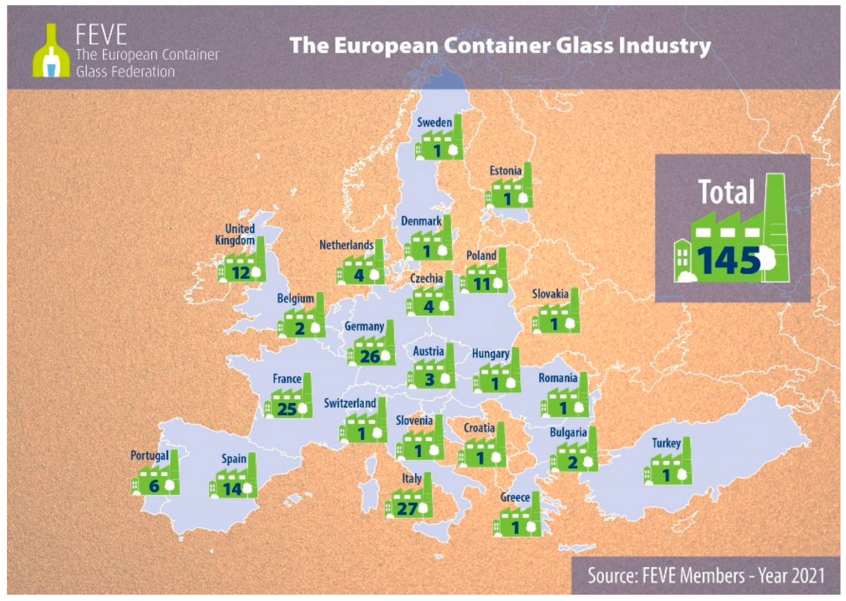
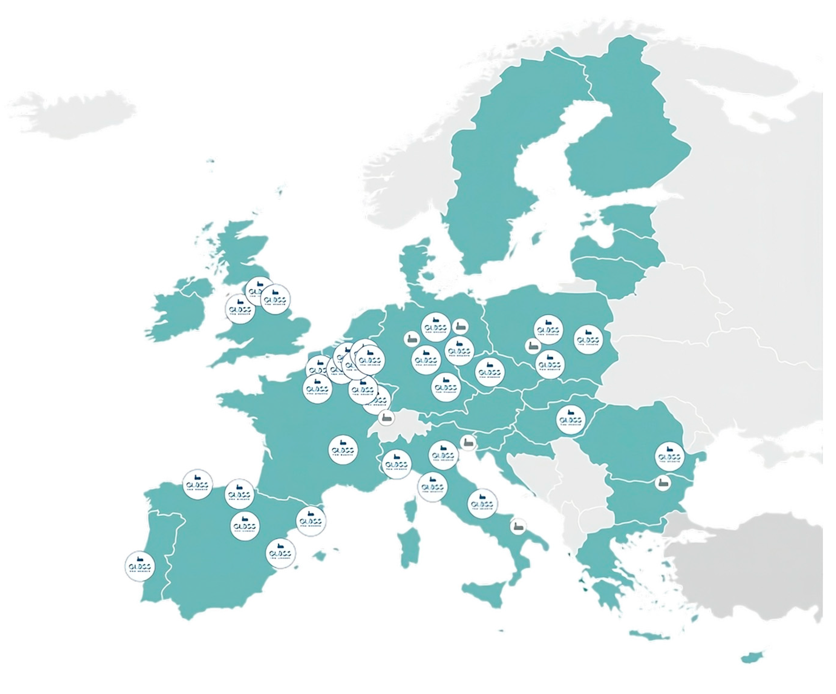
In Europe, there are currently 145 glass production sites for container glass; the highest number of factories is located in Italy, with 27 plants, as shown in Figure 1 [15].
European manufacturers of glass containers for food and beverages, and bottles for perfumery, cosmetics and pharmaceutical markets—members of the European Federation of Glass for Containers (FEVE)—produce 22 million tons, equivalent to over 80 billion containers per year. Their almost 150 production plants are located in 23 European countries. They generate 125,000 jobs across Europe of which 44,000 are direct jobs in the glass industry. For each direct job, 1.9 indirect jobs are created. Glass production generates about 6100 jobs per million tons of glass produced. The industry invests around 610 million euros each year to decarbonize its plants. The European hollow glass industry emits about 11 million tons of CO2 annually out of the total 2 billion tons declared with the European Emissions Trading System, representing 0.5% of all European CO2 emissions.
The glass production process begins with the preparation of the batch mixture, consisting of:
  • a mixture of virgin raw materials consisting of quarry minerals (silica sand, feldspar sand, dolomite, marble) and inorganic chemical synthesis products (soda Solvay, sodium sulfate);
  • glass cullet, partly from the plant’s quality control-rejected production (internal cullet), partly purchased from external suppliers, that acquire raw glass waste coming from the separate collection of municipal solid waste (which cannot be recycled directly in glass plants) and then the main contaminants are removed, such as fragments of ceramics, plastics, metals, lead glass, glass ceramics, etc., in dedicated treatment plants, thus producing a secondary raw material called “furnace ready” cullet.
For both the hollow and flat glass sectors, the so-called soda lime silicate glass is produced. Table 1 gives typical ranges for the various components of its chemical composition, expressed as constituent oxides. Knowing the yield factor, which is the ratio between the weight of the produced glass and the weight of the raw materials and cullet mixture, whose value is lower than 1 due to the release of CO2 from some raw materials (namely soda ash, limestone and dolomite) through the chemical reactions that take place in the melting phase, it is possible to obtain the precise composition for the particular cases [16].
The compositions in terms of element weight percentages, limited to flat glass, are shown in Table 2.
The mixture of minerals and cullet is called “batch” and is prepared on-site in large mixers. It is distinguished between “raw batch”, meaning the mixture of only virgin raw materials, and “mixed batch” when it also includes cullet. The batch can be humidified with water or caustic soda to reduce particle segregation during transport via conveyor belts from the mixer to the furnace. The batch preparation is an all-electric phase that consumes about 4 percent of the total energy required by the plant [18]. In the melting phase, the batch is fed into the so-called melting tank. There, temperatures over 1500 °C are reached by burning fuel and using electric boosting via electrodes submerged in the melt. After the mixture is melted and homogenized, the refining phase takes place (elimination of the gas bubbles trapped inside the melt). The final molten glass comes out of the furnace at a temperature of around 1350 °C from a submerged duct called the “throat”, which connects the melting basin with the “working-end” (or forehearth).
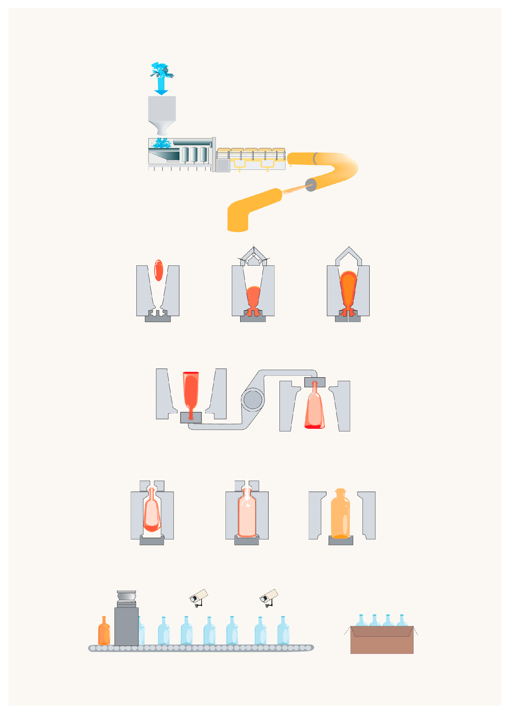
The working end has the task of pre-conditioning the glass before it enters the channels: the molten glass is cooled gradually and homogeneously to achieve the correct working viscosity. To ensure an optimal gradient, the glass temperature is detected with special immersion probes, connected to the automatic regulation system, and several small burners are installed along the walls of the forehearth; submerged electrodes are sometimes also used for heating purposes. Like the working end, channels and feeders are also equipped with burners for heating and air-cooling systems (chimneys with adjustable dampers, fans for forced cooling, etc.) for cooling. In the terminal part of the channels, the system responsible for the formation of the glass gobs is installed, and suspended from above. It consists of a pair of concentric cylindrical components called the tube and plunger, made in refractory material, immersed in the glass bath: the tube is a rotating cylinder driven by an electric motor, which mechanically stirs the molten glass near the outlet orifice (called the spout), making the temperature profile homogeneous; the plungers are refractory punches (one per spout) pushing/extruding the vitreous mass through one or more spouts at the base of the channel. Below the spout, the glass gob is cut by mechanically driven metal shears. The forming process can be blow–blow or press–blow. Currently, the most commonly used automatic forming machines are of the IS type (with independent “individual sections”). The manufacturing process for a single section and each gob in the blow–blow case can be outlined as follows:
  • The gob is cut from the shears and falls into the gob distributor, the lubro-refrigerated system that directs the drops to almost zero friction towards the various sections of the forming machine;
  • The drop falls by gravity to the bottom of the mold;
  • During settling time, the container mouth/finish is formed;
  • A punch opens a first small cavity inside the mouth, then retracts, and compressed air is blown inside, thus forming the blank by blowing;
  • The blank mold opens and the blank is transferred by overturning to the finishing mold;
  • The finishing mold closes, the blank undergoes temperature homogenization and the blowing head is positioned;
  • The blank is blown with compressed air until the final shape is obtained;
  • The mold opens and the container is placed by push-outs onto the exit conveyor.
The blank and the finishing mold are cooled with forced air from a dedicated fan system. To prevent the glass from sticking to the molds, the molds are generally lubricated using an oxyacetylene flame in oxygen defect, which develops carbon black on the contact surface; if necessary, the molds can also be manually lubricated with graphite oil using specific swabbing tools.
Subsequently, the containers undergo a hot-end treatment, annealing and a cold-end treatment: the still red, hot hollow glass products formed by the IS machines pass first through the hot treatment hood. Here, they are invested by a spray of SnCl4 or mono-butyl-tin–tri-chloride, to cover the outer surfaces with a thin film of SnO clusters. It acts as a “primer of adhesion” for the protective anti-friction treatment (cold treatment), deposited later. The hot-end-treated products are then fed by a cross-conveyor inside the annealing tunnel (or lehr), where they are kept for an appropriate period at a temperature regime sufficient to relax the thermal stresses generated by the inhomogeneous and sudden cooling imparted by the molds. Then, they are allowed to cool in a controlled manner up to about 100 °C, the temperature at which they exit the tunnel. The annealing furnace is divided into zones, each one characterized by a specific temperature. The section with the highest temperature is located at the entrance. The annealing furnace is heated by natural gas combustion. Depending on the furnace, the burners are blown air or venturi type. The oxidizing air is taken directly from the working environment. The combustion gases leaving the annealing furnace are dispersed in the environment.
Downstream of the annealing lehr exit, auxiliary cooling fans are installed. Then, the external surfaces of the products are sprayed with an aqueous dispersion of an organic compound (usually polyethylene derivatives), called cold end treatment It clings to the clusters of SnO deposited by the hot treatment and forms an anti-friction film; it has the function of reducing the friction between the products (or with foreign surfaces) in the subsequent stages of the life of the container, with the ultimate aim of preserving the surfaces as much as possible from scratches and cracks, which would impair their mechanical strength. When the product is cold, an accurate automatic in-line quality control is carried out to verify the conformity of the container to the product specifications. The containers not considered suitable are eliminated from the line and consequently recycled in the same production process, to be re-molten as internal cullet. In the end, products are packaged and stored. The process is schematized in Figure 2.
Sources: authors, [7,16,19,20,21,22].
According to data extracted from energy diagnosis by ENEA [19], the process energy consumption is divided as follows:
  • Preparation of the batch mixture: <5%.
  • Melting: >60%.
  • Fabrication (working end, conditioning channels, forming, hot end treatment, annealing and cold end treatment): >10%.
  • Final phases: <5%
  • Auxiliary services (compressors, fans, pumps, chillers, pollution control system, etc.): >10%
  • General services (lighting, winter heating, summer cooling, etc.) <5%.
It is evident how, in order to decarbonize the process, it is necessary to focus on the melting phase, more precisely on the melting furnace.

2.2. The Flat Glass Sector

The flat glass sector is also a primary business-to-business industry. The products are basic glass sheets, that most of the time are transformed into final products through downstream processes: for example, they may be thermally toughened, laminated, or assembled with other products. Flat glass is mainly used in the construction and automotive sectors. Similarly, to the container glass sector, flat glass production is a capital-intensive activity; the same reasoning is valid both for the presence on the market exclusively of large companies with large capital availability and for the long investment cycle. Flat glass furnaces can last up to 20 years; after this period, a partial or complete reconstruction of the structure is required. A simple furnace reconstruction costs EUR 30–50 million, the entire float line with 500 tons per day of production costs EUR 100–150 million. The production sites produce on average between 400 and 700 tons of glass per day. Flat glass also has high transport costs; therefore, it should be processed and sold in the proximity of the production plant. In the European Union, the flat glass sector is the second largest sector in glass production. Currently, about six major companies with over 60 production sites, almost all associated with the Italian Federation Glass for Europe (Figure 3), produce about 10 million tons of flat glass each year. If, in addition to flat glass production plants, processing plants are also considered, the number of companies involved increases to more than 1000, for an equivalent of 100,000 direct employees and over 500,000 indirect employees. Over EUR 100 million are invested in the research and development field of this sector [23]. Glass Alliance Europe declared 11 million tons for the basic flat glass sector in 2022, produced in Europe27 + the United Kingdom [12].
Flat glass is made using the so-called “float process”, invented by Sir. A. Pilkington in the 1950s. After the raw materials are melted in furnaces conceptually similar to those of the container glass sector but typically larger in size and production capability, the melt is poured by a specially designed “lip” onto a molten tin bath, above which it “floats” (having a lower density). It forms a perfectly flat and “polished” ribbon with plane parallel faces and minimum surface defects or textures (mirror-like appearance). The use of molten tin is motivated by the fact that it is the only viable material liquid at a temperature range centered around 600 °C. The tin bath is surrounded by an atmosphere of nitrogen and hydrogen to prevent oxidation of the bath itself. The floating molten glass is distributed on the tin bath by suitable rollers that mechanically pull the glass to ensure that the output glass ribbon achieves the desired thickness and width. Float glass can be made between 3 and 19 mm thick. The glass then enters the annealing phase, which consists of heating and cooling the glass in a controlled manner within a tunnel heated by radiating electrical elements (no burners), to remove the residual stresses that could impair mechanical properties in service life. The glass is cut to the desired sizes at the end of the annealing process. Relative to the energy consumption of the flat glass production process, experts say that the melting phase involves about 80–90% of the total consumption of the production process. Similarly to the hollow glass production, in order to decarbonize the process, it is thus necessary to focus on the melting furnace. The process is showed in Figure 4.
Sources: authors, [7,16,18,19].

2.3. Industrial Production

The global recession of 2008 and the COVID-19 emergency influenced the production volumes of all glass sectors.
Hollow glass is the most important of the eight sectors reported, in terms of production. In 1996, in the European Union (15 Member States), container glass accounted for 60% of total production, followed by the flat glass sector with 22%. Surveys dating back to 2005 on European Union25 confirmed the trend, with values of 53% (20 million tons) and 24.8% (9.37 million tons), respectively. Among the remaining glass sectors, the mineral wool sector is the next most important in terms of production volume [7].
Glass Alliance Europe has reported an updated overview of European production over the years for the various sectors annually. As already reported in the previous paragraph, in 2022, Glass Alliance EU declared for Europe27 + the United Kingdom 11 million tons of production for the flat glass production sector (not accounting for secondary transformation into products such as laminated glass, windows, etc.) and 24.50 million tons for the container sector in 2022 [12].
Regarding Italian production, relying on ISTAT’s data, for 2020, 5.34 million tons of molten glass were produced, equivalent to 15.4% of the European production. The Italian supply chain consists of 32 large production companies, 60 factories and over 300 flat glass secondary processing companies, generating about EUR 6 billion in turnover [24].
According to ISTAT data reported in Assovetro’s annual reports, the trend of Italian production is reported in Table 3:

3. State of Energy Consumption and Pollutant Emissions

Glass production is an energy-intensive activity due to the high temperatures required to melt glass in furnaces; important quantities of CO2 emissions are emitted in the process. Unlike other sectors, consumption and emissions are continuous and more or less constant during the solar year for the whole service life, which can go up to 15 years for the container glass sector and up to 20 years for float glass furnaces, with potential fluctuations only connected to production modulation to follow the market demand (if any), to changes in availability of cullet (that impact fuel consumption) and rare shutdowns of the furnace for extraordinary maintenance (typically once during the service life).

3.1. Energy Consumption

In 2007, around 0.5–0.8 EJ of energy was used worldwide for the production of glass. Considering that in those years, half of the production was realized burning natural gas and the other half using oil, on average 7 GJ per ton of product was necessary. A survey of the same period on 28 float glass furnaces in China, that used 25% of glass cullet, showed an average consumption of 7.8 GJ per ton of glass, 20% above the world average and 32% above the most advanced countries. In addition to the above consumption, it is necessary to consider post-melting transformations, mainly forming and annealing for hollow glass, and annealing for flat glass; these processes require an additional energy consumption of 0.52 GJ of electricity and 0.42 GJ of natural gas per ton for hollow glass and 0.8–1.5 GJ (depending on the final thickness of the ribbon) per ton of flat glass, respectively [9].
ENEA’s (Italian National Agency for New Technologies, Energy and Sustainable Economic Development) “Quaderni dell’efficienza energetica—Settore Vetro” is one of the most recent research documents about energy performance indexes; for flat glass, ENEA found an average plant energy consumption index of 7039 MJ/ton, based on the sample of Italian producers, with a production range between 170,000 and 250,000 tons/year. For the container glass sector, again for plants based in Italy, they found a 6627 MJ/ton plant energy consumption index for production between 30,000 and 124,999 tons/year, and a 5497 MJ/ton plant energy consumption index for production between 124,999 and 400,000 tons/year [19].
The energy cost has a significant impact on the production of glass—more than 20% of total costs—with significant effects on the competitiveness of companies; i.e., Italian companies are at a disadvantage compared to European counterparts due to higher energy costs [34].
The recent study of the Boston Consulting Group notes an even higher importance of the energy component in total production costs, equal to 27% [35].
The main energy vectors used for glass production are natural gas and electricity. Assovetro in Italy estimates the glass sector using about 1.08 billion Sm3 of natural gas and 3 TWh of electricity, emitting 2.5 million tons of CO2eq per year, equal to 0.41 ton CO2 per ton of glass produced [24]. Natural gas is more used than electricity: that is because of the technical difficulties in constructing fully electric furnaces and gas’s cost-effectiveness, purity, ease of control and lack of special requirements for storage. Electricity, however, combined with natural gas, provides part of the heat in the furnace through the Joule effect, delivering the current into the molten glass through electrodes and thus heating it resistively. Electricity is then used in the plant for the operation of various machinery in the post-melting phases (e.g., forming) and for the production of compressed air and cooling air (from fans). Fuel oil in Europe had almost disappeared in recent years for several reasons, first of all environmental ones (mainly to lower SOx emissions); however, in the recent Ukraine war and energy prices crisis, fuel oil has experienced an unexpected “comeback”.
The use of a mixture of gas and hydrogen instead of pure natural gas is currently being researched. The total energy consumption of a glass production plant typically ranges from 85% gas/15% electricity to 65% gas/35% electricity. Still, different proportions can be encountered depending on the production sector, glass color, etc.
The study realized by Assovetro on 17 Italian companies (from both the container and flat glass sectors) sampled, reported specific global consumption of 0.18 ton of oil equivalent/ton molten glass; 0.12 ton of oil equivalent/ton molten glass depended on natural gas, 0.05 on electricity and 0.01 on other sources [34].

Energy Consumption in the Melting Phase

As already reported, the first phase of the production process is the melting step.
The mixture of virgin minerals requires a certain initial energy to achieve melting, consisting of three components:
(1)
Enthalpy required to heat the mixture to the process temperatures;
(2)
Latent heat of reaction: i.e., the heat necessary to carry out the chemical reactions between minerals that transform the mixture of crystalline compounds into a homogenous “molten” amorphous material;
(3)
Enthalpy required to heat the CO2 released by the thermal calcination of limestone, dolomite and soda ash, up to the process temperatures.
The minimum theoretical energy demand for melting a ton of glass is a debated topic: 0.76 MWh/ton (equivalent to 2.74 GJ/ton) [7] or 2.8 GJ/t for soda lime glass and 2.35 GJ/t for borosilicate and crystal [9], or 2.68 GJ/metric ton for a soda–lime–silica glass formulation according to Sinton [36]. The minimum energy for chemical reactions is 0.5 GJ/t, for heating 1.8 GJ/t [1]. According to Sinton [36], the real amount of energy required varies from two to fifteen times (e.g., for very small and not efficient furnaces, such as for artistic glass) the theoretical minimum, typically remaining below 8 GJ/ton for large melting furnaces. According to IEA [9], the real energy required varies between 5.75 GJ/t and 9 GJ/t. The distance between theoretical and actual consumption depends mainly on heat losses. A total of 20–25% of the energy input is lost in structural heat losses from the body of the furnace (0.85 GJ/t), while 25–35% of the energy is lost with exhaust gases (1.18 GJ/t) released into the atmosphere downstream of the heat recovery/air preheating system (regenerator, recuperator, etc.) [9]. The values vary in function of the product to be realized; flat glass must have a quality (minimum imperfections) that is higher than other types of glass products, therefore the residence time of the molten glass in the furnace is longer and consequently the specific energy consumption is higher. The glass industry has invested in reducing the gap between theoretical and real consumption. Compared to other materials and other energy-intensive processes, the specific energy consumption of glass is close to cement (5.4 GJ/ton) and much lower than steel (25.4 GJ/ton) and paper (32.8 GJ/ton).
Energy consumption varies in function of the final product color too; it depends on the different maximum amounts of cullet that can be recycled, with every 10% of cullet added lowering the melting energy consumption by approximately 2–3% [3,37]. The same value of 2.5% in energy savings, for the same cullet-added quantity, is also reported in the Klaassen study [38]. Generally, we can distinguish glass colors between colored glass and white/half white (also called flint/half flint) glass for the hollow sector, and flint or extra clear glass in the case of flat glass (with smaller production also of tinted glass). If the final product has to be colorless, there are much stricter limits as to the amount of external cullet that can be fed to the melting furnace; it depends on the chromophore and refractory impurities that can be present in the cullet coming from the recycling of post-consumer material, and the high level of quality demanded from the final product.
However, there are even more factors involved in energy consumption, such as the “energy mix” that can be used in melting furnaces, with larger shares of electrical boosting increasing the overall efficiency of the furnace: in fact, the efficiency of Joule heating by electrodes can even exceed 90% (only transformation losses and conductor losses). Combustion efficiency is lower, and strongly dependent on the oxidizer nature (pure O2 being intrinsically more efficient than air) and temperature (air is typically preheated recovering the energy of waste gases in heat recovery systems such as refractory regenerators or metallic recuperators, the former being more efficient than the latter), and on the temperature at which waste gases leave the heat recovery systems. In particular, for the production of colored glass, a larger share of electrical boosting is typically used compared to flint glass production; the issue of increased consumption for flint glass is recognized by ENEA, which [19] states that in the case of the prevailing production of flint and half-flint glass, in the evaluation of the overall (efficiency) indices which are specific to the main (production) activities, the reported standard deviation used to determine the confidence interval shall be multiplied by 1.5, to take into account the relatively higher consumption levels.
ENEA’s researchers found in the sample of Italian flat glass energy-intensive companies, with a production range between 480 and 660 tons/day, an average furnace energy consumption index of 6.320 MJ/ton (furnaces are all of the regenerative cross-fired type). For the container glass sector, they found the following average furnace energy consumption indexes (furnaces are for the vast majority of the end-port regenerative type):
  • 5.56 MJ/ton (production between 40 and 149.99 tons/day);
  • 4.83 MJ/ton (production between 150 and 209.99 tons/day);
  • 4.42 MJ/ton (production between 210 and 289.99 tons/day);
  • 3.95 MJ/ton (production between 290 and 500 tons/day).
The study realized by Assovetro on 17 Italian companies (from both the container and flat glass sectors) sample, reports specific furnace consumption of 0.11 ton of oil equivalent/ton molten glass. 0.09 ton of oil equivalent/ton molten glass depends on natural gas, 0.02 on electricity [34].

3.2. Polluting Emissions

According to the latest studies, the IEA studies of 2007, with half of the production of glass made via burning natural gas and the other half with fuel oil, on average 7 GJ per ton of product was needed, which corresponds to an emission factor of 450 kg of CO2 per ton of product. Overall, the energy used for producing flat and hollow glass corresponds, in the study, to 50–60 million tons of CO2 emitted each year. The calcination of soda and other carbonate virgin raw materials contributes up to 200 kg of CO2 per ton of product, depending on the specific composition of the glass, batch formulation and the amount of cullet used [9].
As already reported, the production processes of hollow glass and flat glass are energy-intensive and reach very high temperatures, mainly through fuel combustion. The results are not only the relevant emissions of CO2, NOx and SOx, but also of dust, originated mainly as a result of the volatilization and condensation of the volatile materials of the batch (sulfates, sodium, etc.); there are also traces of chlorides and fluorides and metals, present as impurities in virgin raw materials and cullet. The amount of emissions depends on the type of glass produced, the raw materials, the type of melting furnace and the fuel used.
The great advantage of glass at an environmental level is its ease of reuse and recycling, the very low consumption of water for its production, which is limited to just cooling and cleaning applications, and that can be easily treated and recycled in a closed or quasi-closed loop.
More specifically, the following pollutants are produced in the different phases, as shown in Table 4:

CO2 and Other Pollutant Emissions

Emissions, regulated in Europe by the Industrial Emissions Directive, are reduced through primary and secondary measures. The main pollutants are CO2 emissions. It is essential to distinguish between combustion and process emissions: combustion emissions are related to the use of fossil fuels for heating furnace and glass batch to obtain the final product. To reduce these emissions, there are two approaches: the first consists of making the production process more efficient, therefore consuming less fuel and, consequently, producing fewer greenhouse emissions; the second approach consists of replacing fossil fuels with other CO2 leaner energy vectors: electricity, which also has a higher energy transfer efficiency than natural gas combustion and can also have a lower CO2 footprint if produced from renewable sources (emissions would otherwise only be moved from the factory to the fossil-fuel-fired power plant), biogas and bio-methane, or hydrogen produced from renewable sources.
The overall plant efficiency at the global scale is growing steadily as the best available technologies and best practices for energy efficiency are spreading from Europe, the US, Japan, etc., towards the rest of the world, not only for the melting phase but also for downstream processes. Improvements include increased cullet utilization, recovery of waste gas heat with primary (regenerators, recuperators) and enhanced systems (batch and cullet preheaters, steam or ORC turbines, etc.), and the design and construction of state-of-the-art furnaces. Process emissions derive from the calcination of the carbonate raw materials, mainly Na2CO3 (sodium carbonate), CaCO3 (calcium carbonate) and CaCO3·MgCO3 (dolomite) and can be reduced only via decreasing the input of virgin raw materials (e.g., increasing the amount of cullet in the batch), changing them (e.g., using pre-calcined raw materials), or through CO2 capture actions [39].
Combustion emissions typically account for 80% of total glass plant emissions, while the remaining 20% comes from the decomposition of carbonates [24]. The same values are confirmed by Glass Alliance Europe, which estimates the first between 75% and 85%, and the second between 15% and 25% [39].
The study realized by Assovetro on 17 Italian companies (from both the container and flat glass sectors) sampled, reported specific emissions of 0.334 tons of CO2/ton molten glass, and 0.381 tons of CO2 eq ETS/ton of molten glass [34].
The whole glass sector is considered an approximate intensity of 733 kg CO2/ton of glass produced, 77% of this CO2 is from fuel combustion during the manufacturing process, and the remaining 23% is from electricity production [40].
As already reported, in addition to CO2 emissions, it is important to consider the production of other types of pollutants such as nitrogen oxides (NOx), sulfur oxides (SOx) and dust.
NOx in the process is mostly (95%) produced by direct oxidation at high temperatures of the nitrogen present in the air (T > 1300 °C), with the formation of NO (about 90–95% of the total) and NO2. The remaining share of NOx is generated because of the presence of nitrogen in fuels—generally a very low share, but in fuels from the North Sea, nitrogen can reach 13–15%—or because of the use of NaNO3 for the production of extra clear glass which requires a strong oxidation of the melt.
The SOx derive mainly from the addition in the batch of sodium sulfates with the function of fining agents (200–800 mg/Nm3 of SOx), or from the sulfur present in the fuel; in this case, it is necessary to distinguish between the case of sulfur present as an impurity in the fuel oil, which in the combustion phase is oxidized to SO2 and in lower quantities SO3, and the latter present in natural gas. The concentration of SOx in the combustion fumes is very different depending on the fuel used, going from more than 2000 mg/Nm3 in the case of fuel oil to 300–800 mg/Nm3 of SOx when using natural gas.
Dust derives mainly (typically more than 90%) from the condensation of sodium sulfate Na2SO4, which is formed within the waste gases by a reaction between Na and NaOH evaporated from the melt with the SO2 coming from fining and combustion. The generation of dust in this way depends on the temperature of the melt surface, the angle of inclination of the burners, the amount of water present in the combustion atmosphere and the characteristics of the soda ash. The remaining part of dust is formed by the decrepitation of dolomite (bursting of dolomite grains during calcination, with the production of fine dust) and by carryover (i.e., dragging of the finest particles of the batch by the turbulence of waste gases); also, in this case, the quantity that is formed is a function of the angle of the burners, of turbulence, of the grain size distribution and humidity of the batch, as well as the quality of the dolomite. Finally, other dust generated may be linked to the presence of inorganic substances in the combustion oil, if used.
At a European level, thanks to the introduction of stringent environmental regulations and the consequent spread of primary and secondary measures for emission reductions, these polluting emissions have been significantly lowered in the last few decades: according to the Stazione Sperimentale del Vetro database of experimental emission measurements, on average emissions of nitrogen oxides have been reduced by 44% from 2003 to 2019, and the reduction in dust, from the years before the installation of ESP and bag filters to 2019, exceeded 98%.

4. Current and Developing Technologies/Solutions

Decarbonizing the whole glass sector by 2050 is a titanic endeavor; considering that the average service lifetime of a furnace is about 15 years, from this year to 2050 there will be just two or three furnaces rebuilds before the deadline; this means that in at a maximum three generations of furnaces, the industry must become carbon neutral.
For this reason, researchers in the glass industry are looking for innovative solutions that are at the same time effective, efficient and economically sustainable. Many proposals have been launched recently, and many operational experimentations on a pilot scale or industrial demonstrator scale are currently under way.
Some technologies and solutions aim to reduce energy consumption and, consequently, CO2 emissions. Others act directly on either not producing or abating CO2 emissions.
The technologies that will be described in the following sections are not all mature, or applicable to the various branches of the glass industry; some of them are even mutually exclusive: which means the implementation of one of them does not allow the adoption of others with the same purpose or with a different purpose but relying on the same part of the process (e.g., competition between different waste gases heat recovery solutions). It is, therefore, necessary to be very careful not to consider the gains that can be made from each technology as linearly additive.

4.1. Increased Combustion Efficiency and Reduced Residence Time of the Glass in the Furnace

Combustion efficiency can be improved by adopting suitable burners; “Low NOx” burners for example, by reducing the volume of combustion air close to stoichiometric levels, decrease the amount of inert nitrogen that is heated without participating in the combustion process, and thus increase the energy efficiency.
The residence time of the glass in the melting tank depends on the quality level that it is necessary to achieve in the final product: it is a function of the furnace temperature, batch composition, the size of the grains of virgin raw materials, the size of the glass cullet fragments, of the management of flames’ hot-spots, of electrical boosting and, in general, of the management of convective currents. Due to the low viscosity of the initial eutectics formed during the early stages of batch reactions, the batch may tend not to mix properly, requiring longer homogenization times. To overcome this problem, some batch components have tailored grain sizes. To increase homogenization, it is not always recommended to increase the temperature of the furnace since it reduces the life of the refractory lining; in some cases, bubblers are installed at the bottom of the tank [41], that is, nozzles strategically positioned to inject air to stir and stimulate beneficial convective currents in the melt; in some other cases, a line of electrodes is installed at the bottom in a tailored position; the purpose is the same, creating a rising flow of hot glass that stimulates the formation of a beneficial convective pattern within the tank.
Energy losses through the furnace structure can reach up to 30% of the energy input. The not-perfect adiabaticity of the furnace leads to a heat loss directly connected to the primary energy consumption. These losses are inversely proportional to the size of the furnace due to the change in the ratio of the surface area to the volume of the melt. Beyond the dimensions, the refractory blocks in contact with the melt are typically made of densely fused cast alumina–zirconia–silica (AZS) material, with high thermal conductivity, and therefore they need to be thermally insulated; moreover, not all parts, depending on the furnace area and operating conditions, can be insulated. However, it must be considered that, even if increasing insulation reduces energy losses, it increases the operating temperatures of the refractory lining: this enhances its corrosion by glass and waste gases, reducing its overall service life, so an “equilibrium” must be reached. An overheating of the refractory material can also degrade and fragment the material itself, resulting in the melt and undermining its final quality [36].
Finally, burners must be properly positioned: the angles between the axis of the burner, the combustion air vein and the surface of the glass are carefully set up. This makes significant differences in the amount of natural gas needed to melt a ton of gas and in the production of thermal NOx [42,43,44].
Industry is always looking for greater combustion efficiency by also resorting to sophisticated automated burner control systems, AI-driven expert systems, etc. Residence times tend to be maximized to ensure the necessary glass quality; the bubbling technique is being phased out in favor of barrier boosting due to the engineering problems it entails and to the benefits the energy delivered from barrier electrodes can bring to the melting and fining processes. The furnace structure insulation is already maximally optimized by furnace manufacturers; further insulation may risk impairing furnace service lifetime by enhancing corrosion rates by the melt and combustion atmosphere (due to the higher temperatures that refractories would reach on their inside-facing surfaces). Great attention is paid to the correct angles of inclination of the burners; all these solutions/technologies are well known and, when convenient, adopted.

4.2. Waste Heat Recovery from Fumes

The recovery of waste heat from flue gases to preheat combustion air is already universally applied in air/fuel glass melting furnaces, with air temperatures reaching around 800 °C for metallic recuperator systems and exceeding 1200–1250 °C for refractory regenerators (Glass Alliance Europe [39]). It is estimated that flue gases emitted into the atmosphere are responsible for energy losses, representing 25–30% of the energy used in the furnace [45].
Nowadays, unit-melters (i.e., furnaces with metallic recuperators) are being phased out all around Europe in favor of the more efficient regenerative furnaces; this is a well-known kind of furnace that uses regenerators with a periodic change in flame directions [46]; regenerator design has almost achieved the asymptotic maximum engineering achievable efficiency, with checkers or cruciform new designs usually focused on maintaining good efficiency in the long term and on minimizing fouling and clogging (that would impair energy recovery and even furnace operation).
The frontier of energy saving from waste gases nowadays relies on the recovery of the residual heat of waste gases coming out of the regenerator/recuperator, which still have a usable enthalpic content.
Several technologies have been already proposed to reuse this residual energy, for example, to preheat the cullet and/or the batch, the fuel, to produce electricity or to feed a district heating system.
All these technologies are incompatible with all-electric melting since the off-gases produced by these furnaces (mainly calcination CO2) have a negligible enthalpic content (low flow rate and low temperature) [39].

4.2.1. Cullet and/or Batch Preheating

The installation of systems for preheating cullet and/or batch is a viable technology [47], known since the 1980s and already mentioned in the BREF [7]. The first-generation systems were characterized by the evaporation of the moisture of the batch and the dehydration of the soda, causing problems of agglomeration and blocking the flow of the batch in the preheater [45].
The batch/cullet preheating, currently exploited only for furnaces in the hollow glass sector, can take place directly, with the feed entering in contact with fumes at about 400 °C, or indirectly, by the plate heat exchanger and in counter-current flow. This allows the heating of the material up to 300 °C [43]. Using a clean cullet may partially prevent the fume and odor problems [48].
Energy savings are estimated at 0.8 GJ/ton glass, but electricity needs to increase by 0.02 GJ/ton; generally, fuel savings are estimated at 0.76 GJ/ton, with a 50–60% cullet percentage used [38]. In the case of only pre-heating cullet, the diffusion of the technology is still limited due to logistical problems, the emission of problematic decomposition compounds and management of the incoming material, limiting its application to a few units in Italy [19]. If the energy of the fumes is used for the preheating of the batch and cullet together, the mix must contain more than 40% glass cullet, otherwise problems of clogging and dust deposition tend to arise. Using a pelletized batch would solve the dust problem and remove the limitation of 40%, but the technology is not yet mature [39]. According to BAT, it would be possible to install the system in batch furnaces containing at least 50% cullet and, at the time of publication, there was also a furnace operating with the above system and a percentage of cullet in the batch as low as 30%. In this way, the batch can be heated up to 300 °C while the exhaust gases can be cooled to 200–250 °C. These systems’ energy savings are estimated at 12–20% [43,45].
This type of technology has been known for years. Still, its application is limited to a few units because of the logistical problems presented above, in addition to those of emissions and clogging/loss of efficiency (less severe in new generations of equipment). Moreover, the technology has a large layout footprint, is cumbersome and highly capital intensive. However, it is one of the most thermally efficient ways of recovering waste gas heat directly into the process.

4.2.2. District Heating System

Waste gas’s residual heat can also be recovered outside the glass production process, for example, via district heating [49]. This solution requires several favorable boundary conditions, such as the proximity of clients for the use of such heat, a sufficiently developed infrastructure, easy bureaucratic paths, etc. A concrete example has been realized in Reims, in France, from a plant of O-I Manufacturing, where the residual heat of the furnace is used to heat the houses of the neighboring districts [50].
An application example of this technology in Italy is present in Cuneo where at least 400 utilities are served by the district heating system connected to the AGC plant [51].
This solution is convenient, but is season-dependent (even with absorption chillers installed for summer cooling demand); it requires a district heating infrastructure already in place and a “neighbourhood” that has a strong demand for heat. As already mentioned, there are real situations in which this solution has been successfully implemented.

4.2.3. Electricity Generation through SRC or ORC Turbines

Residual waste gas heat can also be recovered via the electricity production in a turbine exploiting the steam Rankine cycle or an organic Rankine cycle [52,53]. With a heat source at 450–500 °C such as waste gases downstream of the regenerator, the expected electrical efficiency varies between 15 and 19% [45].
Organic Rankine cycle turbines are the most widespread for this application: they are more flexible and less impactful on the glass process upstream. Steam turbines are quite rare due to the risk of formation of wet steam (and consequent destructive corrosion) in rotors/stators in case of fluctuation in the temperatures of the starting fumes [19].
An Italian example already operational includes the 0.5 MWe organic Rankine cycle generator at the OI Glass container plant in Villotta di Chions, Italy [54].
Organic Rankine cycle turbines are mature, but the energy benefit that can be obtained is inferior to other technologies, especially to ones directly recovering the heat into the process; in Italy, the spread of this solution has been facilitated by the possibility of financing it through national incentives for energy efficiency; even in this case, the high capital cost of the technology has prevented its evolution into a mainstream solution.

4.2.4. Steam Methane Reforming: The SUGAR Project

The SUGAR project, whose acronym stands for “SUstainable Glass: Architecture of a furnace heat recovery system including a steam Reformer”, co-funded by the European Union’s LIFE program (LIFE19 CCM/IT/001314), aims to use the residual energy of waste gases of air/fuel furnaces to preheat a part of the natural gas input and to transform it into syngas via a catalytically activated steam-methane reforming reaction. It is expected to save around 15% in terms of energy consumption and avoided CO2 emissions. The technology will be first implemented in a “Centauro”, a hybrid regenerative/recuperative furnace, but applications to oxy-fuel furnaces and regenerative furnaces are under development. The reaction to produce syngas is strongly endothermic so the waste gases are cooled down to 200 °C, which is the minimum temperature to avoid sulfuric acid condensation, by reforming only approximately 1/3 of the fuel input of the furnace.
The Centauro furnace, invented in 2008, has several features that make it ideal for the SUGAR project:
In the regeneration chamber of a regenerative furnace, there are about 8–9 m of medium-low “checkers” that work at relatively low temperatures, compatible with a metallic heat exchanger; in the Centauro furnace, the height of the regenerator is halved, and downstream the “half height” checker works a metallic heat recuperator (similar to unit-melters) is installed. For the SUGAR Centauro, the hybrid heat recovery system has been specifically dimensioned so that in the refractory duct connecting the metallic and refractory sections, there is an ideal temperature regime for a catalytically activated steam reforming reactor.
The objectives of the first testing phase, to be realized on 1:5 scale in the Abbiategrasso (Milan, Italy) plant of Bormioli Luigi by the end of 2024, are:
  • Finding the best catalyst for the process conditions.
  • Defining the optimal layout for the steam methane reformer reactor.
  • Analyzing the behavior of flames and emissions from the combustion of produced syngas.
The project, starting on 1 June 2020 and ending in 2024, is being developed by Stara Glass, Kinetics Technology, Johnson Matthey, Stazione Sperimentale del Vetro and the University of Genoa [11].

4.3. Electrical Boosting State of the Art

Installing electrodes in the bottom or in the sidewalls of furnaces to deliver extra heat (with respect to fuel combustion) to the melt is commonly referred to as “boosting”. Similar to burners, the electrodes must be also well positioned [55].
Boosting is generally used to increase the maximum pull of combustion furnaces (in response to peak demand scenarios), to deliver heat to the bottom of colored glass melts (where heat transfer from the flames towards the bottom of the melt is hindered by the stronger absorption) and to control fining and homogenization convective currents. From 22 to 28 kW of power is required to increase the daily pull rate by 1 ton/day [36].
The electric boosting usually provides from 2% to 20% of the energy requirement of a melting furnace. Generally, however, the contribution in flat and hollow glass furnaces varies between 5% and 15% [43].
This is a very common solution, nowadays adopted in practically all furnaces in Europe.

4.4. Process Electrification and Super-Boosting

Although complete process electrification would eliminate CO2 and other pollutant emissions produced by fossil fuel combustion (leaving only process emissions), the implementation is nowadays limited by the maximum size of the available all-electric furnace designs, by the composition of the glass to be produced (amber and certain green glasses being challenging) and by the relatively low upper limit imposed on cullet.
At present, only small electric melting furnaces (with a capacity of less than 200 tons/day) are in service [56], while only engineering and CFD studies are available for melting furnaces with capacities exceeding 200 and approaching 400 tons per day. It is not clear if this technology can be up-scaled [57] to the production range typical of present-day flat glass furnaces [58]. The Boston Consulting Group study reported a 30% maximum electrification of the process limit due to technological limitations [35].
Cold top all-electric vertical melters would be the most thermodynamically efficient method for glass production, because heat is directly delivered to the melt via the Joule effect, without energy losses to combustion gases; calcination gases pass through the batch blanket, thus preheating it on their way out; and heat dispersions towards the environment are minimized since the only hot parts of the furnace are those in contact with hot glass and batch (no hot superstructure to contain the combustion space, no hot regenerator, etc.).
However, there are also present technology engineering downsides like reduced specific pull rate (tpd per square meter), limits to maximum cullet usage, problems with certain colored glasses (e.g., amber) and, most importantly, at present the maximum pull rate achievable is only 200–250 tons per day, i.e., in the low-medium capacity range for container glass, and well below the minimum capacity of flat glass furnaces (that ranges from 500–600 tpd to above 1000 tpd).
All electric melters also have shorter service lifetimes, reaching a maximum of 8 years versus the 10–15 years of regenerative furnaces; this is not necessarily a downside, since without the huge capital costs of regenerators, the investment is reduced, and more frequent furnace rebuilds may translate in steadier implementation of technology upgrades (smaller, safer “steps” every 8 years instead of huge, riskier “leaps” every 15 years).
To overcome production capacity and color limitations of the present day all-electric melters, several CFD studies have been performed and are underway by many furnace designer companies (e.g., FIC, Sorg, Horne, Fives, etc.), and most converge towards the design of a horizontal electric hybrid furnace, that works approximately with 80% electricity, by exploiting the Joule effect through submerged molybdenum electrodes, and 20% by heating the upper surface from the top through combustion (typically oxygen—natural gas, or even oxygen—hydrogen), or in some cases with electrically powered radiating heating elements.

The Furnace for the Future Project and Other Hybrid Furnaces

Furnace for the Future (F4F) was a project to reduce CO2 emissions from the glass container production process. Altogether, 19 independent European manufacturers of glass containers were cooperating to build together the first large-scale hybrid electric furnace that can operate with 80% of electricity from renewable sources.
The objective was to operate a large-scale furnace (350 ton/day) to produce amber glass that can range from 20% to 80% of its needs with electricity, at the same time increasing the percentage of usable cullet to 70%. Unlike traditional electric furnaces, which are vertical, this new type would be horizontal. Because of its composition, the color of the amber glass is more difficult to achieve with electric melting: amber glass is colored by the so-called amber chromophore, a colloidal complex of ferric iron ions and sulfide ions. This combination of an oxidized and a reduced component is achieved by tight control of the redox state of the glass. The corrections needed to maintain this redox state destabilize the batch blanket of a fully electric furnace. The reaction required between the sulfate components to introduce sulfur and carbon as a reducing agent to transform part of the sulfur into sulfide causes the development of reaction gases that potentially destroy the balance of the batch blanket. Previous tests to melt colored glasses containing the amber chromophore or a combination of chromium (III) oxide and amber chromophore have not been successful. With the combination of electric boost and top firing, these problems will be solved by a batch blanket that can move and release gas into the combustion space of the heated furnace. If this project was successful, it would also be applicable to flint glass and green glass. Therefore, based on commercial demand, the project involved the production of scale amber, flint and green glass.
A reduction in CO2 emissions of 60% compared to traditional plants was expected. Since 80% of emissions come from melting, replacing 80% of natural gas with electricity from renewable sources would result in high CO2 savings, reducing the bottle’s carbon footprint. Furthermore, increasing the possibility of using cullet would also significantly reduce process emissions. This project would need a high-quality glass cullet, separated by colors.
According to FEVE’s LCA studies, the production of a glass bottle releases 0.79 kg CO2eq per kg of formed and finished glass, considering emissions from the factory, raw material producers, conveyors, energy producers and glass cullet carriers, up to the emissions needed to collect, recycle or dispose of the containers at the end of life.
The demonstration project was planned for construction in 2022, with the first results in 2023 [59]. It was to be funded by the EU Innovation Fund; the unexpected price increases brought about by the energy and materials crisis of 2021–2022 to all furnace construction materials (steelworks, refractories, technologies) led to a strong overshooting concerning the available budget, so the project was aborted. The design principle of hybrid furnaces, however, is solid and is being at present implemented by several pioneering plants in the EU; the disclosure of the first results in terms of production quality and energy efficiency by these furnaces is expected in the next few years.

4.5. Pre-Calcination of Raw Materials

As already reported, the decomposition of carbonates in the batch represents an important part, about 20%, of the CO2 emissions of glass companies; these emissions cannot be avoided with energy efficiency measures that reduce only emissions from the combustion of fuel.
The reduction in these emissions using pre-calcined Ca- and Mg-bearing primary raw materials, or even carbonate-free secondary raw materials such as mineral waste from other processes, e.g., slag from the metal industry, instead of virgin materials, is currently being studied in the container glass sector [39]. However, the use of pre-calcined lime (CaO) and dolime (CaO·MgO) is already a proven technological solution for the glass fiber production sector [60].
This is one of the few primary solutions to reduce process emissions of melting furnaces, and is quite effective even in lowering the global CO2 emissions balance (including upstream scope 3 emissions, that are GHG emitted by raw material suppliers), since calcination kilns for limestone and dolomite are much more efficient at pre-calcining minerals than glass furnaces, that need to operate at much higher temperatures and with designs optimized to produce high-quality glass. However, the exploitation of lime and dolime still requires some study before its substantial spread to the container and flat glass sectors; the economic sustainability of this raw material substitution is to be proven in the present-day scenario since it is strongly impacted by the balance between energy and CO2 emission prices.

4.6. Hydrogen

Recently, many countries have been evaluating hydrogen as a strategic CO2 lean fuel/energy vector, preparing national plans for its implementation. In the future electrical power grid, non-programmable renewable sources (photovoltaic and wind) are going to play an ever greater role and hydrogen is considered a possible solution for storage of excess energy (power-to-gas scenario): H2 could be generated by electrolyzers using electricity produced in excess—for example, by photovoltaic (PV) modules fields during the day or by windmill fields in strong wind conditions, and then stored in a compressed state; stored hydrogen could be converted again into electricity via fuel cells in peak electricity demand hours—although this is not recommended given the low net efficiency of the double conversion “power-to-gas-to-power”—or, much more efficiently, be burned directly as a fuel for a high-temperature production process; moreover, it can become a chemical feedstock for the organic or inorganic chemical industry (including iron and steel production).
Using green electricity to produce hydrogen (around 80–90% efficiency) and then burning it to produce glass (likely 50 to 70% efficiency, it has yet to be proven at a full-size industrial scale) would lead to a modest net overall efficiency. Considering the technical limitations of the present day all-electric furnaces, and the need for at least 20% combustion energy in the proposed designs of near-future hybrid furnaces, H2 still looks like one of the most promising CO2 lean fuel solutions available.
Depending on the energy source used to produce it, hydrogen takes a different name and has a different estimated impact on the environment in terms of carbon footprint, shown in Table 5:
Many consider hydrogen one of the most promising solutions towards decarbonization, especially looking at hard-to-abate industries, using natural gas in large quantities [62].
Burning hydrogen instead of traditional fuels allows the production of heat with zero CO2 direct emissions. Several studies and projects are under consideration for the insertion of hydrogen directly into the pipelines already used by natural gas in variable percentages (so-called “blending”), or for the creation of dedicated transport infrastructures.
The glass industry has begun to study how their processes would react to the combustion of a mixture of gas and hydrogen or pure hydrogen.
Some preliminary studies have postulated that fusing hydrogen in melting furnaces would make the heat transfer to the glass melt and batch less efficient, as the hydrogen flames are much less luminous than those from natural gas [39]. However, more recent research works have shown that predicting radiating energy transfer efficiency by flame luminosity alone can be misleading and that the amount of heat delivered by air/hydrogen flames and O2/H2 flames to test rigs simulating glass melting furnaces is substantially comparable to that of conventional air- and oxy-natural gas flames, if not slightly better [20,21,63].
According to some estimates made by Assovetro, a 400 ton/day furnace would need to be fed by about 1 ton/hour of hydrogen, which would correspond, if extended to the whole sector, to a power consumption by electrolyzers of at least 13 GW, all to be supplied by photovoltaic panels or wind turbines, which represents a serious challenge for the power generation and transport grid [9].

4.6.1. The DIVINA Project

In Italy, in 2021, some companies working together launched the DIVINA project “Decarbonisation of the Glass Industry: hydrogen and new equipment”. It aimed to contribute to reducing GHG emissions in the glass industry through using hydrogen as fuel. The working group is composed—in addition to important glass groups—of representatives of the entire supply chain: specialists in the energy sector, players in the field of production and transport of fuel, leading companies in the certification and integration of complex systems, glass melting furnace design companies, universities and research centers. The initiative aims to evaluate, in the short and medium term, the result of introducing an increasing percentage of hydrogen mixed with natural gas, in existing melting furnaces and regular production. The opportunity to test significant quantities of hydrogen on operating furnaces aims to verify the compatibility of hydrogen-based combustion with glass, batch and furnace refractories in real industrial production contexts and after appropriate laboratory trials. In the medium and long term, the project will help to define and optimize new furnace design rules that can guarantee all the necessary performance for ever-increasing added hydrogen percentages [64].

4.6.2. The HyGlass Project

In North Rhine-Westphalia, Germany, the German glass industrial association, BV Glass, has received funding to investigate, in partnership with the GWI Institute in Essen, the effects of replacing natural gas with hydrogen in glass furnaces. The research will be gradual, starting from low percentages of hydrogen in blending until reaching the complete substitution of natural gas; in this case, the German glass industry alone could reduce its carbon footprint by about 3.3 million tons of CO2 a year. Specifically, the aim is to analyze combustion efficiency, heat transfer, pollutants produced (such as NOx), temperatures reached, CO2 produced, safety aspects, product quality, service life of the furnace elements, etc.
The results have been obtained using computational fluid dynamics simulation systems and test facilities.
High-temperature test devices are used: powers (firing rates) up to 1.2 MW, with preheated air up to 1250 °C, furnace temperatures up to 1600 °C and a hydrogen mixture up to 330 m3/h. A first measurement campaign took place in December 2020, where data were collected on the production of CO CO2 NOx O2, varying percentages of hydrogen blending (10, 30, 50 and 100%) and variable momentum burners (variable momentum lance). The tests continue, investigating the effects on the quality of the glass obtainable from different batches (green, brown, white, float) in other operating conditions and different blending percentages.
Computational fluid dynamics simulations performed on a regenerative design furnace in excess air and at a constant preheat air temperature at 1400 °C showed that the temperature distribution remains very similar to natural gas firing. The “Heat Transfer Impact Factor” is reduced with low values of hydrogen blending and then recovers and grows at 50% blending. However, with a 20% volume hydrogen blending, only a 7% reduction in emissions is achieved: this is a limited value, but still significant considering the possibility of rapid adoption and without considerable impact for the end users (no need for changes to the plant) [65,66].
Recent industrial test campaigns that have taken place with hydrogen/natural gas blending or even 100% H2 combustion trials, the most outstanding being the one successfully performed at 15% volume blending in the giant NSG St. Helen’s float glass furnace (usually burning 5000 Sm3/hour of natural gas), have demonstrated that the use of hydrogen as fuel in glass melting furnaces potentially represents one of the most technically straightforward solutions to decarbonize the industry. The most challenging aspect of this solution is not the modifications potentially required to furnace and burner design, which are expected not to be “groundbreaking”, but the availability of green hydrogen in the necessary large amounts for all glass manufacturing plants, and at a price competitive with natural gas (including CO2 emissions costs); this represents a substantial liability for the sector, since the “rate determining step” for this green transition cannot be controlled by glassmakers, but is in the hands of governments and of the renewable power generation and gas distribution industries.

4.7. Biogas/Biomass

Biogas produced from biomass is a possible renewable alternative to natural gas, in the glass industry fields [67,68]; however, its potential is strongly limited by the amount of sustainable biogas producible against the enormous quantities required by the sector. The English study “Biomass in a low-carbon economy” foresees a maximum potential of 15% of the English energy demand by 2050 against 7% today [39].
The BCG study foresees a potential use of up to 30% of biogas, depending on availability [35].
Some energy companies from biomass-fired thermal power plants are using exclusively uncontaminated plant material as fuel from the agricultural and forestry sectors, especially as residues, also from forestry interventions and the maintenance of river beds. One example is the Fossalta di Portogruaro Zignago group plant, where there is an internal combustion thermoelectric plant with a thermal output of 49.2 MWt, for a gross electricity production of about 17 MWe. In this case, the biomass is not used for the production of biogas but for electricity, which can still be used for the supply of the electrodes of the melting furnace, reducing the production of indirect CO2 [69].
Some studies have suggested using biomass ash as a promising alternative raw material, valuable for reducing both energy and emissions [70].
On the subject, the hollow glass producer Encirc and the research and development organization Glass Futures are carrying out a project in Derrylin, Northern Ireland, which aims to make new bottles with 100% recycled glass using only energy from ultra-low-carbon biofuels, reducing the carbon footprint of each bottle by 90% [71].
Recently, for the flat glass sector, Saint Gobain, in its plant in Aniche (in the north of France), for a week successfully produced glass with zero CO2 emissions, using 100% cullet, biogas and green energy from renewable sources [72].

4.8. Oxygen Combustion

In most present-day glass melting furnaces, combustion takes place by burning fuel with preheated air. However, it is possible to use pure oxygen to meet part or all of the oxidizer demand [73].
Therefore, oxy-combustion has been a proven technology since the 1990s, and several oxy-fuel furnaces are at present in operation in the hollow glass sector, although far fewer in the flat glass sector due to the higher amount of oxygen that would be needed and, therefore, the higher operating costs. When adopted, energy savings concerning air/fuel furnaces may range between 20% and a maximum of 45% when replacing a furnace at the end of service life; even in comparison with state-of-the-art regenerative furnaces, fuel savings may range between 5 and 20% [74].
Others estimate an 8–10% CO2 savings compared to a state of art end port regenerative furnace of 4 GJ/t glass specific energy consumption, 220 kg/t glass direct CO2, 76% cullet, and 92% natural gas [49].
This technology also reduces 70–90% of NOx emissions and 25–80% of particulate matter compared to traditional air systems. Other benefits include reduced noise and melting times. Disadvantages are greater wear of the refractory and, therefore, reduced service life of the furnace, and the costs of production of the oxygen (the cost of a plant for on-site production of oxygen amounts to approximately 10% of the costs of investment for the melting tank).
To achieve an additional 10–15% energy saving compared to conventional air/fuel (e.g., regenerative) furnaces, the energy of oxy-fuel combustion waste gases can be exploited to perform a regenerative steam methane reforming reaction in the natural gas feed (Praxair’s Optimelt technology) [75,76].
Moreover, a potential alternative solution has been proposed by Air Liquide with its Heat-Ox technology, developed in the LIFE HotOxyGlass project: in flat glass production, the energy consumption was reduced by approximately 25% (concerning reference regenerative furnaces performance) and the CO2 emissions by 15% by preheating both oxygen and fuel exploiting the heat recoverable from waste gases; also, NOx was reduced by 83% and SOx by 83% [77].
By using only oxygen, exhaust gas flow rates were significantly reduced, from 10.53 to just 3 cubic meters per cubic meter of natural gas introduced; this reduced the heat lost with fumes and saved fuel.
Oxy-combustion is, compared to other solutions, a technology already developed; the behavior of foam, refractory and redox state during melting is well known, NOx emissions are reduced and the quality of the color yield (gloss) is improved, as is the quality of the glass [78].
This solution is well known; the most important limit to its spread is at present the high capital and operative costs of on-site O2 production units. Based on the forecasts for future development of green electricity generation and depending on the spread of solutions involving the simultaneous production of oxygen and hydrogen (i.e., electrolyzers), oxy-combustion, and especially oxy-hydrogen combustion, could see large-scale application in the next few decades.

4.9. Carbon Capture Storage and Carbon Capture Utilization on Site

The capture and storage of CO2 is one of the key strategies for mitigating climate change [79] and it could abate the entirety of GHG emissions of glass manufacturing plants, including process emissions arising from the calcination of raw materials. Today, however, there is a severe lack of infrastructure for both the transport and storage of CO2 to make this technology a viable large-scale solution.
In addition to these “storage” problems, there are also technical issues to be solved in the “capture” stage, such as: the large encumbrance of capturing equipment, the presence of acid compounds in the waste gases hindering capture reactions, low concentration of CO2 in the flue gases, very high off gas flow rates required to reach financial sustainability for the CCS plant with current technologies, etc. [39].
Among the immediate measures to be applied for the decarbonization of the glass sector by 2030, BCG suggests CCUS tests to capture medium-low% process emissions at the most emissive sites in northern Italy [35].
An oxy-combustion furnace with carbon capture storage is estimated to reduce CO2 emissions by up to 75%. However, it is a technology with an estimated market entry starting not before 2030 [80].
There is speculation about the use of low-carbon hydrogen through steam methane reforming coupled with CCUS [81].
Depending on the creation or not of the necessary infrastructure for CO2 transport and storage, this solution could have a bright future in the transition to zero-CO2 production, or never be applied on a large scale. Unfortunately, as in the case of H2, this “rate determining step” is outside the glassmakers’ control, and will need the commitment of politicians and of the oil and gas extraction and transport industry to become reality.

4.10. Other Solutions

There are also other types of technologies: an example is the high-temperature microwave heating, defined often as a promising technology [82,83,84,85]. Some studies report this technology could be used to reduce CO2 emissions [86,87]. This technology is theoretically researched but without specific applications or investments known.
Some researchers mention the use of plasma to melt raw glass powder as a promising technology to also reduce CO2 emissions [73,88,89].
Another solution investigated is submerged combustion melting (SGM), usable also with natural gas; it consists of putting burners on the bottom of the glass furnace, maximizing heat transfer because of direct contact of combustion gases with the molten material and batch [47,90,91].
It is also possible to implement energy-saving measures in other parts of the glass production plant, not only in the melting furnace. Some examples are:
Installation of high-efficiency transformers, replacing the old ones, that are air-cooled (less efficient) and oversized for current needs.
Compressors: optimization of the compressor fleet and search for leaks within the compressed air distribution system; if compressed air is used for cooling, stirring or mixing of glass, compressors can be replaced with blowers or fans; if they are used to create a vacuum, with vacuum pumps. In particular, interventions related to compressed air are typically very effective:, compressed air, used mostly in the hollow glass industry, is one of the most expensive forms of energy vector used within the industrial plant because of its low efficiency [43].
Installation of high-efficiency HVAC systems.
Optimization of cooling systems, with implementation of controls, speed and flow rate balance.
Installation of heat recovery systems on the thermal strengthening, toughening or annealing furnaces.
Motors: it is possible to install variable speed motors, re-establish belt tensioning, rewire them, install inverters and/or replace them with hydraulic motors or gearboxes.
Lighting: installation of LED and lighting control systems in time. Also, the interventions related to the saving of electricity used for lighting, which usually approaches 5% of the total consumption of electricity in the plant, are profitable, both for the ease of construction and for the low cost of intervention.
The identification and the realization of the most promising energy efficiency upgrades depend on the characteristics of the specific productive site, and require an in-depth analysis of feasibility and cost–benefits.

5. Subdivision into Technologies/Solutions Implementable in Short and Medium Term

This paragraph and Table 6 summarize the technologies/solutions reported in the preceding sections, with their feasibility and degree of maturity. Nine main technologies were found, plus several others gathered in the category “other solution” which include the main actions applicable to the entire plant and some technologies only theorized or for which no current industrial application or projects were found. Most of these nine solutions have a high maturity and can be implemented immediately or in the short term. Some have a medium level of maturity. Hydrogen combustion and process electrification have a low maturity, but there are many research projects in that field that are currently active.

6. Conclusions

As an outcome of the deep state-of-the-art analysis carried out by the authors, this paper shows how the global production of glass has not increased substantially on a worldwide scale. This is due to a balancing effect between some regions experiencing an increase in production (like in Europe), while for other regions, the production is nowadays decreasing. The most relevant sectors of the EU glass industry in terms of production are the container and flat glass ones. An in-depth analysis of the Italian situation in terms of volume of production and related energy consumption has also been reported, given the availability of detailed and recent data from Italian studies. There are only a few other recent studies that have investigated to a certain extent the specific energy consumption and emissions of these sectors and their melting furnaces. In addition to the state-of-the-art analysis, the authors have also had the chance to receive direct feedback from interviews with experts, that have given them insights into information not easy to find in the existing literature due to the nature of the confidentiality of the industrial processes. Indeed, energy and CO2 costs have an important relevance on the final product cost, and thus on the market competition: acquiring an innovative technology that allows the reduction in energy consumption or CO2 emissions becomes a strategic element, therefore open disclosure of performance (i.e., efficiency or specific consumptions) data, if not mandated by legislation (as was the case of the recent Italian ENEA studies, based on data deriving from mandatory energy audits), is not seen favorably by glassmakers.
This study also investigated technologies and solutions currently at the R&D level, together with their feasibility, degree of maturity and industrial readiness in the glass industry. The confirmed or estimated savings data were reported, when available.
Analysis and interviews revealed that there are few immediate high maturity technologies/solutions that have been implemented in most plants, such as the combustion efficiency control and increase in electric boosting power share; oxy-fuel combustion is another mature and immediately implementable technology, but its spread at present is limited by the available infrastructure and the high costs of oxygen production (mainly due to high electricity prices). The study also showed some other implementable solutions with a short or medium-term maturity, but they still need some research or testing activities for complete validation. Some of the most promising solutions of this type are hydrogen combustion and process electrification.
Based on the discussed solutions and the present situation in the European Union context, it is recommended for the glass industries to deploy in the short term all of the easily implementable technologies and to invest in R&D for the others, depending on site-specific boundary conditions, especially the presence of adequate infrastructure and costs of energy carriers. Moreover, it is worthy of note that, due to the wide variety of glass applications and production types, melting furnaces vary in sizes and types/technologies. Accordingly, it is very difficult to standardize solutions for energy and emissions savings, and a case-by-case approach needs to be developed. Moreover, some of the technologies discussed are mutually exclusive, so the implementation of one would not allow the adoption of selected others.
Despite all the foreseen difficulties during this transition period, the longer-term outlook is undoubtedly positive.
Indeed, the glass sector has great importance given the magnitude of energy consumption and related emissions, and its decarbonization will become a key-player in the whole journey towards the achievement of 2050 goals. Furthermore, the already proven R&D technologies for reducing CO2 emissions give a positive outlook on a large-scale implementation, making the energy transition for the glass industry promising.
This paper is the starting point for studies able to evaluate and quantify in a techno-economic manner the potential of alternative solutions to reduce CO2 emissions.

Author Contributions

Conceptualization, D.A. and S.T.; methodology, D.A., S.T. and M.V.; validation, S.T., M.V. and M.G.; formal analysis, S.T. and S.M.; writing—original draft preparation, D.A.; writing—review and editing, D.A., S.T., M.V. and S.M.; supervision, M.G. All authors have read and agreed to the published version of the manuscript.

Funding

This research received no external funding.

Data Availability Statement

No new data were created or analyzed in this study. Data sharing is not applicable to this article.

Acknowledgments

The work was completed thanks to Assovetro and Stazione Sperimentale del Vetro. Stazione Sperimentale del Vetro (SSV), the Italian research centre and specialized accredited testing laboratory that provides technical and scientific support to the entire glass industry at the national and international level, supported this publication, due to the great interest in defining the most suitable technologies. Thanks also go to the University of Roma Tor Vergata for supporting the XXXVII Ph.D. program.

Conflicts of Interest

The authors declare no conflict of interest.

References

  1. Un Green Deal Europeo. Available online: https://commission.europa.eu/strategy-and-policy/priorities-2019-2024/european-green-deal_it (accessed on 11 June 2023).
  2. European Climate Law. Available online: https://climate.ec.europa.eu/eu-action/european-green-deal/european-climate-law_en (accessed on 25 October 2022).
  3. Emission Trading Europeo. Available online: https://www.isprambiente.gov.it/it/servizi/registro-italiano-emission-trading/contesto/emission-trading-europeo (accessed on 11 June 2023).
  4. Carbon Border Adjustment Mechanism. Available online: https://taxation-customs.ec.europa.eu/carbon-border-adjustment-mechanism_en (accessed on 11 June 2023).
  5. Accordo di Parigi. Available online: https://climate.ec.europa.eu/eu-action/international-action-climate-change/climate-negotiations/paris-agreement_it (accessed on 21 September 2022).
  6. National Long-Term Strategies. Available online: https://commission.europa.eu/energy-climate-change-environment/implementation-eu-countries/energy-and-climate-governance-and-reporting/national-long-term-strategies_en (accessed on 11 June 2023).
  7. European Commission, Joint Research Centre, Institute for Prospective Technological Studies. Best Available Techniques (BAT) Reference Document for the Manufacture of Glass: Industrial Emissions Directive 2010/75/EU: Integrated Pollution Prevention and Control; Publications Office: Luxembourg, 2013. [Google Scholar]
  8. Griffin, P.W.; Hammond, G.P.; McKenna, R.C. Industrial Energy Use and Decarbonisation in the Glass Sector: A UK Perspective. Adv. Appl. Energy 2021, 3, 100037. [Google Scholar] [CrossRef]
  9. International Energy Agency. Tracking Industrial Energy Efficiency and CO2 Emissions; OECD: Paris, France, 2007; ISBN 978-92-64-03016-9. [Google Scholar]
  10. Sengupta, P. Refractories for Glass Manufacturing. In Refractories for the Chemical Industries; Springer International Publishing: Berlin/Heidelberg, Germany, 2020. [Google Scholar] [CrossRef]
  11. Cattaneo, E. LIFE SUGAR PROJECT—The Idea of Total Recovery Glass Furnace. Hydrogen in Glass Making. 15 June 2021. Available online: https://www.glass-international.com/hydrogen-in-glass-manufacturing/view-the-presentations (accessed on 8 January 2022).
  12. Assovetro. Relazione Annuale Assovetro 2023; Assovetro: Rome, Italy, 2023. [Google Scholar]
  13. Ojovan, M.I.; Yudintsev, S.V. Glass, Ceramic, and Glass-Crystalline Matrices for HLW Immobilisation. Open Ceram. 2023, 14, 100355. [Google Scholar] [CrossRef]
  14. Siddika, A.; Hajimohammadi, A.; Mamun, M.A.A.; Alyousef, R.; Ferdous, W. Waste Glass in Cement and Geopolymer Concretes: A Review on Durability and Challenges. Polymers 2021, 13, 2071. [Google Scholar] [CrossRef]
  15. FEVE Plants. Available online: https://feve.org/feve-plants/ (accessed on 8 January 2022).
  16. Ceola Introductory Training Course for Glass Producers—SSV—1° Day. Venice. Available online: https://www.spevetro.it/corsi-formazione/ (accessed on 24 November 2021).
  17. CEN/TC 129; EN 572 Glass in Building—Basic Soda-Lime Silicate Glass Products. Glass for Europe: Brussels, Belgium, 2012.
  18. Pellegrino, J.; Greenman, M.; Ross, C.P. Energy and Environmental Profile of the U.S. Glass Industry; Office of Industrial Technologies Energy Efficiency and Renewable Energy, U.S Department of Energy: Washington, DC, USA, 2002. [Google Scholar]
  19. ENEA. Quaderni Dell’efficienza Energetica—VETRO; Martini, C., Martini, F., Salvio, M., Toro, C., Eds.; ENEA: Rome, Italy, 2021; p. 170. ISBN 978-88-8286-413-2. [Google Scholar]
  20. Hubert, M. IMI-NFG Course on Processing in Glass: Lecture 3: Basics of Industrial Glass Melting Furnaces; Celsian Glass & Solar: Eindhoven, The Netherland, 2015. [Google Scholar]
  21. Shelby, J.E. Introduction to Glass Science and Technology; Royal Society of Chemistry: London, UK, 2005; ISBN 978-0-85404-639-3. [Google Scholar]
  22. Beerkens, R.G.; van der Schaaf, J. Gas Release and Foam Formation During Melting and Fining of Glass. J. Am. Ceram. Soc. 2006, 89, 24–35. [Google Scholar] [CrossRef]
  23. Key Data—Flat Glass Market. Glass Eur. Available online: https://glassforeurope.com/the-sector/key-data/ (accessed on 10 June 2023).
  24. Assovetro. L’industria Del Vetro in Italia—Sfide Ed Opportunità per Un Materiale al Centro Della Transizione Ecologica; Assovetro: Rome, Italy, 2021. [Google Scholar]
  25. Assovetro. Relazione Annuale Assovetro 2014; Assovetro: Rome, Italy, 2014. [Google Scholar]
  26. Assovetro. Relazione Annuale Assovetro 2015; Assovetro: Rome, Italy, 2015. [Google Scholar]
  27. Assovetro. Relazione Annuale Assovetro 2016; Assovetro: Rome, Italy, 2016. [Google Scholar]
  28. Assovetro. Relazione Annuale Assovetro 2017; Assovetro: Rome, Italy, 2017. [Google Scholar]
  29. Assovetro. Relazione Annuale Assovetro 2018; Assovetro: Rome, Italy, 2018. [Google Scholar]
  30. Assovetro. Relazione Annuale Assovetro 2019; Assovetro: Rome, Italy, 2019. [Google Scholar]
  31. Assovetro. Relazione Annuale Assovetro 2020; Assovetro: Rome, Italy, 2020. [Google Scholar]
  32. Assovetro. Relazione Annuale Assovetro 2021; Assovetro: Rome, Italy, 2021. [Google Scholar]
  33. Assovetro. Relazione Annuale Assovetro 2022; Assovetro: Rome, Italy, 2022. [Google Scholar]
  34. Assovetro. Rapporto Di Sostenibilità; Assovetro: Rome, Italy, 2022. [Google Scholar]
  35. Boston Consulting Group. Industrial Decarbonization Pact: Un’alleanza per la piena decarbonizzazione dei settori Hard to Abate; Boston Consulting Group: Boston, MA, USA, 2022; Available online: https://web-assets.bcg.com/2b/79/89d157b44d9090a549bec316bcf4/working-paper-industrial-decarbonization-pact.pdf (accessed on 11 November 2023).
  36. Sinton, C.W. Glass and Energy. In Encyclopedia of Energy; Cleveland, C.J., Ed.; Elsevier: New York, NY, USA, 2004; pp. 1–10. ISBN 978-0-12-176480-7. [Google Scholar]
  37. Rademaekers, K.; Zaki, S.S.; Smith, M. Sustainable Industry: Going for Growth & Resource Efficiency; ECORYS: Rotterdam, The Netherlands, 2011. [Google Scholar]
  38. Klaassen, G.; Berglund, C.; Wagner, F.; Amann, M. The GAINS Model for Greenhouse Gases—Version 1.0: Carbon Dioxide (CO2); International Institute for Applied Systems Analysis, IIASA: Laxenburg, Austria, 2005. [Google Scholar]
  39. Glass Alliance Europe. The European Glass Sector Contribution to a Climate Neutral Economy; Glass Alliance Europe: Brussels, Belgium, 2021. [Google Scholar]
  40. Industrial Decarbonisation & Energy Efficiency Roadmaps to 2050, Glass; Department of Energy & Climate Change and Department for Business, Innovation & Skills: London, UK, 2015.
  41. Auchet, O.; Riedinger, P.; Malasse, O.; Iung, C. First-Principles Simplified Modelling of Glass Furnaces Combustion Chambers. Control Eng. Pract. 2008, 16, 1443–1456. [Google Scholar] [CrossRef]
  42. D’Antonio, M.; Hildt, N.; Patil, Y.; Moray, S.; Shields, T. Energy Efficiency Opportunities in the Glass Manufacturing Industry. In Proceedings of the ACEEE Summer Study on Energy Efficiency in Industry, Rye Brook, NY, USA, 29 July–1 August 2003. [Google Scholar]
  43. Galitsky, C.; Worrell, E.; Galitsky, C.; Masanet, E.; Graus, W. Energy Efficiency Improvement and Cost Saving Opportunities for the Glass Industry. An ENERGY STAR Guide for Energy and Plant Managers; Lawrence Berkeley National Laboratory: Berkeley, CA, USA, 2008. [Google Scholar]
  44. Laroia, M. Oxy-Fuel Combustion Systems (OCS); LexInnova: Gurgaon, India, 2013. [Google Scholar]
  45. Karellas, S.; Giannakopoulos, D.; Hatzilau, C.-S.; Dolianitis, I.; Skarpetis, G.; Zitounis, T. The Potential of WHR/Batch and Cullet Preheating for Energy Efficiency in the EU ETS Glass Industry and the Related Energy Incentives. Energy Effic. 2018, 11, 1161–1175. [Google Scholar] [CrossRef]
  46. Trier, W. Glass Furnaces: Design, Construction and Operation; Society of Glass Technology: Sheffield, UK, 1987. [Google Scholar]
  47. Levine, E.; Greenman, M.; Jamison, K. The Development of a Next Generation Melting System for Glass Production: Opportunities and Progress. In ACEEE Summer Study on Energy Efficiency in Industry; ACEEE: Washington, DC, USA, 2003. [Google Scholar]
  48. Beerkens, R. Energy Saving Options for Glass Furnaces & Recovery of Heat from Their Flue Gases and Experiences with Batch & Cullet Pre-Heaters Applied in the Glass Industry. Ceram. Eng. Sci. Proc. 2009, 30, 143–162. [Google Scholar] [CrossRef]
  49. Papadogeorgos, I.; Schure, K.M. Decarbonisation Options for the Dutch Container and Tableware Glass Industry; PBL Netherlands Environmental Assessment Agency: The Hague, The Netherlands, 2019. [Google Scholar]
  50. O-I and Dalkia Heat Homes in Reims, France. Available online: https://feve.org/case_study/oi-france-heat-recovery-system-to-heat-homes/ (accessed on 9 June 2023).
  51. City of Cuneo Taps Factory Waste Heat to Warm Residences. Available online: https://www.automatedbuildings.com/news/jan22/articles/tridium/211229122901triduim.html (accessed on 9 June 2023).
  52. Hubert, M. Industrial Glass Processing and Fabrication. In Springer Handbook of Glass; Musgraves, J.D., Hu, J., Calvez, L., Eds.; Springer Handbooks; Springer International Publishing: Cham, Switzerland, 2019; pp. 1195–1231. ISBN 978-3-319-93728-1. [Google Scholar]
  53. Quoilin, S.; Lemort, V. Technological and Economical Survey of Organic Rankine Cycle Systems. In Proceedings of the European Conference on Economics and Management of Energy in Industry, Vilamoura, Portugal, 14–17 April 2009. [Google Scholar]
  54. Waste Heat Recovery Technologies Largely Used in the European Container Glass Industry to Optimize Energy Consumption and reduce CO2 Emissions. Available online: https://feve.org/case_study/waste-heat-recovery-technologies-largely-used-in-the-european-container-glass-industry-to-optimize-energy-consumption-and-reduce-co2-emissions/ (accessed on 7 June 2023).
  55. Hibscher, C.; Davies, P.; Davies, M.; Davis, D. A Designer’s Insight Into All-Electric Melting. In Proceedings of the 65th Conference on Glass Problems: Ceramic Engineering and Science Proceedings, Columbus, OH, USA, 19–20 October 2004; pp. 131–143. [Google Scholar]
  56. Krijgsman, R.; Marsidi, M. Decarbonisation Options for the Dutch Glass Wool Industry; PBL Netherlands Environmental Assessment Agency: The Hague, The Netherlands, 2019. [Google Scholar]
  57. Wesseling, J.H.; Lechtenböhmer, S.; Åhman, M.; Nilsson, L.J.; Worrell, E.; Coenen, L. The Transition of Energy Intensive Processing Industries towards Deep Decarbonization: Characteristics and Implications for Future Research. Renew. Sustain. Energy Rev. 2017, 79, 1303–1313. [Google Scholar] [CrossRef]
  58. Glass Industry Boss: Replacing Old Windows Can Bring Huge Energy Savings—EURACTIV.Com. Available online: https://www.euractiv.com/section/energy/interview/glass-industry-boss-replacing-old-windows-can-bring-huge-energy-savings/ (accessed on 8 June 2023).
  59. The Furnace for the Future. Available online: https://feve.org/about-glass/furnace-for-the-future/ (accessed on 8 January 2022).
  60. Somerhausen, B.; Di Marino, E.; Hunturk, T.; Ceola, S. Benefits for Fiber Glass Producers to Use Calcium Oxide in Their Raw Material. In Proceedings of the ICG Conference 2017, Istanbul, Turkey, 22–25 October 2017. [Google Scholar]
  61. SORG; Schnurpfeil, D. Some Thoughts about Hydrogen Combustion in Glass Melting. In Proceedings of the Hydrogen in Glass Industry, Hydrogen in Glass Manufacturing, Online, 17 June 2021. [Google Scholar]
  62. CGEP. Challenges and Solutions for U.S. Industrial Decarbonization. Available online: https://www.energypolicy.columbia.edu/publications/challenges-and-solutions-us-industrial-decarbonization/ (accessed on 8 June 2023).
  63. Adendorff, M.; Robert (Bob), L. Bell and Hisashi (Sho) Kobayashi Hydrogen Fired Oxyfuel Burners for Glass Melters. In Proceedings of the ICG 2022 Conference, Berlin, Germany, 3–8 July 2022. [Google Scholar]
  64. redazione. Snam, RINA e Bormioli lanciano il progetto ‘Divina’: Idrogeno per decarbonizzare l’industria del vetro. HydroNews, 21 July 2021. [Google Scholar]
  65. BV GLAS; ESSEN HyGlass. Hydrogen Utilization as a Decarbonization Measure for Glass Industry. In Proceedings of the Glass International: Hydrogen in Glass Manufacturing, Online, 16 June 2021. [Google Scholar]
  66. HyGlass—Process Heat for Industrial Applications. H2-Int. 2021. Available online: https://h2-international.com/2021/12/15/hyglass-process-heat-for-industrial-applications/ (accessed on 1 June 2023).
  67. Fiehl, M.; Leicher, J.; Giese, A.; Görner, K.; Fleischmann, B.; Spielmann, S. Biogas as a Co-Firing Fuel in Thermal Processing Industries: Implementation in a Glass Melting Furnace. Energy Procedia 2017, 120, 302–308. [Google Scholar] [CrossRef]
  68. Torrijos, M. State of Development of Biogas Production in Europe. Procedia Environ. Sci. 2016, 35, 881–889. [Google Scholar] [CrossRef]
  69. Impianti|Zignago Power. Available online: http://www.zignagopower.com/impianti (accessed on 4 June 2023).
  70. Deng, W.; Backhouse, D.J.; Kabir, F.; Janani, R.; Bigharaz, M.; Bingham, P.A.; Marshall, M.; Ireson, R. An Ancient Technology Could Help Deliver Decarbonisation. Glass Int. 2019, 42, 47–49. [Google Scholar]
  71. Encirc-Admin World’s Most Sustainable Glass Bottles Created in Ground-Breaking Biofuel Trial. Available online: https://www.encirc360.com/2021/02/05/worlds-most-sustainable-glass-bottles-created-in-ground-breaking-biofuel-trial/ (accessed on 7 June 2023).
  72. Saint-Gobain Glass:—One Week of Carbon-Free Glass Production. Available online: https://www.gw-news.eu/glass/saint-gobain-glass-one-week-carbon-free-glass-production (accessed on 7 June 2023).
  73. Beerkens, R. Analysis of Elementary Process Steps in Industrial Glass Melting Tanks—Some Ideas on Innovations in Industrial Glass Melting. Ceramics-Silikaty 2008, 52, 206–217. [Google Scholar]
  74. BEIS. Glass Sector Joint Industry—Government Industrial Decarbonisation and Energy Efficiency Roadmap Action Plan; BEIS: London, UK, 2017. [Google Scholar]
  75. Available online: https://www.lifeoptimelt.com/ (accessed on 1 June 2023).
  76. Gonzalez, A.; Solorzano, E.; Laux, S.; Iyoha, U.; Wu, K.t.; Kobayashi, H. Operating Experience with OptimeltTM Regenerative Thermo-Chemical Heat Recovery for Oxy-Fuel Fired Glass Furnaces. In Proceedings of the 76th Conference on Glass Problems, Columbus, OH, USA, 2–5 November 2015; John Wiley & Sons, Ltd.: Hoboken, NJ, USA, 2016; pp. 17–25, ISBN 978-1-119-28247-1. [Google Scholar]
  77. HotOxyGlass Life+|HotOxyGlass Life+. Available online: https://www.oxyfuel-heatrecovery.com/ (accessed on 16 June 2023).
  78. De Diego, J. Hydrogen in Glass Manufacturing—Nippon Gases. Online 16 June 2021. Available online: https://www.glass-international.com/hydrogen-in-glass-manufacturing/view-the-presentations (accessed on 16 June 2023).
  79. Tapia, J.F.D.; Lee, J.-Y.; Ooi, R.E.H.; Foo, D.C.Y.; Tan, R.R. A Review of Optimization and Decision-Making Models for the Planning of CO2 Capture, Utilization and Storage (CCUS) Systems. Sustain. Prod. Consum. 2018, 13, 1–15. [Google Scholar] [CrossRef]
  80. Chan, Y.; Petithuguenin, L.; Fleiter, T.; Herbst, A.; Arens, M.; Stevenson, P. Part 1: Technology Analysis; ICF: Reston, VA, USA, 2019. [Google Scholar]
  81. Sutherland, B.R. Sustainably Heating Heavy Industry. Joule 2020, 4, 14–16. [Google Scholar] [CrossRef]
  82. Dorn, C.; Behrend, R.; Uhlig, V.; Trimis, D.; Krause, H. A Technology Comparison Concerning Scale Dependencies of Industrial Furnaces. A Case Study of Glass Production. Energy Procedia 2017, 120, 388–394. [Google Scholar] [CrossRef]
  83. Mandal, A.K.; Sen, R. An Overview on Microwave Processing of Material: A Special Emphasis on Glass Melting. Mater. Manuf. Process. 2017, 32, 1–20. [Google Scholar] [CrossRef]
  84. Kharissova, O.V.; Kharisov, B.I.; Valdés, J.J.R. Review: The Use of Microwave Irradiation in the Processing of Glasses and Their Composites. Ind. Eng. Chem. Res. 2010, 49, 1457–1466. [Google Scholar] [CrossRef]
  85. Acevedo, L.; Usón, S.; Uche, J. Local Exergy Cost Analysis of Cullet Glass Heating by Microwaves. Appl. Therm. Eng. 2019, 152, 778–795. [Google Scholar] [CrossRef]
  86. Mimoso, R.; Albuquerque, D.; Pereira, J.; Pereira, J. Simulation and Control of Continuous Glass Melting by Microwave Heating in a Single-Mode Cavity with Energy Efficiency Optimization. Int. J. Therm. Sci. 2017, 111, 175–187. [Google Scholar] [CrossRef]
  87. Majdinasab, A.R.; Manna, P.K.; Wroczynskyj, Y.; van Lierop, J.; Cicek, N.; Tranmer, G.K.; Yuan, Q. Cost-Effective Zeolite Synthesis from Waste Glass Cullet Using Energy Efficient Microwave Radiation. Mater. Chem. Phys. 2019, 221, 272–287. [Google Scholar] [CrossRef]
  88. Yao, Y.; Watanabe, T.; Yano, T.; Iseda, T.; Sakamoto, O.; Iwamoto, M.; Inoue, S. An Innovative Energy-Saving in-Flight Melting Technology and Its Application to Glass Production. Sci. Technol. Adv. Mater. 2008, 9, 025013. [Google Scholar] [CrossRef] [PubMed]
  89. Watanabe, T.; Yatsuda, K.; Yao, Y.; Yano, T.; Matuura, T. Innovative In-Flight Glass-Melting Technology Using Thermal Plasmas. Pure Appl. Chem. 2010, 82, 1337–1351. [Google Scholar] [CrossRef]
  90. Springer, C.; Hasanbeigi, A. Emerging Energy Efficiency and Carbon Dioxide Emissions-Reduction Technologies for the Glass Industry; Energy Analysis and Environmental Impacts Division, Lawrence Berkeley National Laboratory: Berkeley, CA, USA, 2017. [Google Scholar]
  91. Submerged Combustion Melter. Available online: https://www.combustion-consulting.com/en/SBM-Furnace/ (accessed on 10 June 2023).
Figure 1. Hollow glass industries in the European Union.
Thermo 03 00039 g001
Figure 2. Container glass process.
Thermo 03 00039 g002
Figure 3. Flat glass industries in the European Union.
Thermo 03 00039 g003
Figure 4. Flat glass process.
Thermo 03 00039 g004
Table 1. Range of the components of soda lime silicate glass, used for the production of hollow and flat glass (source: authors).
SiO2Na2OCaOMgOAl2O3K2O
Weight percentage70.0–73.0%12.0–14.0%8.5–12.0%0.0–5.0%1.0–3.0%0.0–1.5%
Table 2. Magnitude of the proportions by mass of the constituents of soda-lime silicate flat glass [17]; the complement to 100% is Oxygen.
Silicon (Si)Calcium (Ca)Sodium (Na)Magnesium (Mg)Aluminum (Al)Others
Constituents32–35%3.5–10.1%7.4–11.9%0.0–3.7%0.0–1.6%<5.0%
Table 3. Italian production for hollow and flat glass [12,25,26,27,28,29,30,31,32,33].
Years
20142015201620172018201920202021
Hollow glass production (ton)3,626,3763,936,8854,061,9314,177,7114,287,2834,485,1904,429,1104,702,984
Flat glass production (ton)793,211838,019887,125870,4401,054,7631,034,244965,8591,190,251
Table 4. Type of pollutant emitted in the different phases.
Phase of the Production ProcessType of Pollutant Emitted
Raw material handling and weighingDust
CombustionCO CO2 NOx SOx
Decomposition CarbonatesCO2
Decomposition SulfatesSOx
Evaporation Batch and meltDust, HCl, HF, Metals
Condensation of fumesDust (sodium sulfate)
Hot End treatmentSn, HCl, SOx
Cold End treatmentOrganic compounds
Table 5. Summary of different types of hydrogen [61].
Hydrogen DenominationTechnologySourceCarbon Footprint
GreenElectrolyzerSun, wind, water, geothermic, tideMinimal
Purple/PinkNuclear
YellowStored energy from mixed originMedium
BlueFossil Fuel + Carbon CaptureFossil fuel (i.e., natural gas/coal)Low
TurquoisePyrolysisFossil fuel (i.e., natural gas)Medium
GreyFossil Fuel
BrownGasificationBrown CoalHigh
BlackBlack Coal
Table 6. Summary of technologies/solutions reported. Source: authors based on interviews.
Solution/TechnologyMaturityTimes of Research/Implementation
Increased combustion efficiency and reduced residence time of the glass in the furnaceHighImmediate
Waste heat recovery from fumesHighShort term
Electric boostingHighImmediate (for working at maximum available power)/short term (for increasing the maximum boosting power installed)
Process electrificationLowMedium term
Pre-calcined raw materialsHigh/Medium (depending on sector)Short term
Hydrogen CombustionLow (needs development of the H2 production and transport grid, as well as substantial development of renewable electricity generation capacity)Short for low percentage blending with natural gas (on-site or in the grid), Medium for 100% hydrogen/air or 100% H2/O2 combustion
Biogas CombustionMedium (subject to availability issues)Short term
Oxygen CombustionHighImmediate
Carbon Capture Storage and Carbon Capture Utilization on siteMedium (needs development of the CO2 transport grid and of sites for geological storage)Medium Term
Other solutionsHigh for plant efficiency improvement solutions outside the melting tank;|Low for othersImmediate|medium term
Disclaimer/Publisher’s Note: The statements, opinions and data contained in all publications are solely those of the individual author(s) and contributor(s) and not of MDPI and/or the editor(s). MDPI and/or the editor(s) disclaim responsibility for any injury to people or property resulting from any ideas, methods, instructions or products referred to in the content.

