Article

Alterations of a CaCl2 Alginate Composite for Thermochemical Heat Storage during the Hydration in a 1 L Packed Bed Laboratory Reactor

1
F. A. Finger-Institute for Building Material Engineering, Chair of Construction Chemistry and Polymer Materials, Bauhaus-Universität Weimar, Coudraystraße 11A, 99423 Weimar, Germany
2
Department of Chemistry, Institute of Inorganic and Applied Chemistry, University of Hamburg, Martin-Luther-King-Platz 6, 20146 Hamburg, Germany
*
Author to whom correspondence should be addressed.
Thermo 2023, 3(4), 593-604; https://doi.org/10.3390/thermo3040035
Submission received: 30 August 2023 / Revised: 26 September 2023 / Accepted: 30 September 2023 / Published: 10 October 2023

Abstract

:
A composite material of alginate and CaCl2 was tested in a laboratory reactor (1 L) for its ability to thermochemically store heat. The material was exposed to air at 25 °C and 25% RH to prevent the salt from dissolving, and the heat evolution was observed over a period of 15 cycles. To evaluate the changes in the material, samples were taken after 5, 10 and 15 cycles and the material properties and calorimetric characteristics were examined. A change of the material in favor of the heat release was determined, so that an increase of the heat storage capacity from 1.28 kJ∙cm−3 to 2.11 kJ∙cm−3 was detected, with a simultaneous steep decrease of the pore volume in the range from 0.01 to 10 μm. The temperature lift of the reactor showed a significant increase, with the first cycle showing the smallest amount.

1. Introduction

Since 2012, the addition of solar thermal systems has declined worldwide, and this trend did not end until 2020, despite the circumstances surrounding the Corona pandemic. With 640,000 m2, the newly installed collector area in 2021 was approximately at the level of the previous year. Despite this trend, due to weather, the heat generation in 2021 from solar thermal systems was 8.4 billion kWh, approximately five percent less than in 2020 (8.9 billion kWh) [1]. To further advance the construction and use of renewable energy, it is essential to develop more effective seasonal thermal energy to take advantage of the discrepancy between the available heat in summer and the required heat in winter [2]. For seasonal heat storage, thermochemical heat stores are of particular interest, as they have much higher theoretical energy storage densities (100–400 kWh/m3) than sensible (20–100 kWh/m3) and latent heat stores (50–150 kWh/m3) and can be stored without losses [3]. In addition to these three forms, there is also purely adsorptive heat storage, using materials such as silica gel, zeolites or activated carbon [4,5,6]. The storage mechanism here is based on exothermic sorption and endothermic desorption of water on the surface of porous hydrophilic materials. In the case of adsorptive heat storage, the literature is not entirely in agreement; in some cases, it is assigned to thermochemical heat storage, but sometimes it is listed separately [7]. The energy storage densities of these materials can be further increased if these materials are used as porous carrier structures for salts. In addition to the sorption processes mentioned above, energy storage is also based on the absorption and release of water and the associated hydration and dehydration processes of the salts [8,9,10,11]. A large number of salts have already been investigated for their properties for thermochemical energy storage. A salt that has been studied many times is MgSO4, which shows a very high volumetric storage density of 2.2 GJ/m3 between MgSO4∙H2O and MgSO4∙7H2O [12,13]. The generally high possible storage densities are limited by the slow kinetics of the salt. The hydration process can be accelerated by exceeding the deliquescence humidity, but this is a hindrance to its use as a storage material since the salt is washed out of the porous matrix. The combination of MgSO4 with MgCl2, which also causes deliquescence and even increases the storage capacity of the storage material, also has an improving effect [14]. Further investigated salts use H2O as sorbate Li2SO4∙H2O (0.9 kJ/cm3), CuSO4∙5H2O (2.07 kJ/cm3) [15] and promising salt hydrates MgCl2∙6H2O (2.5 kJ/cm3) [16], SrCl2∙6H2O (2.51 kJ/cm3) [17] and CaCl2∙6H2O (2.70 kJ/cm3) [18]. In the case of SrCl2 and CaCl2, all hydrate stages can be achieved at temperatures below 150 °C, which makes these salts interesting for their application in the domestic heating sector. It should be noted that with chlorides, there is the possibility of hydrolysis with the formation of corrosive compounds. Since salts in the form of powders are not very suitable to be used as storage material, there are some investigations to combine the salts with a porous carrier. The already mentioned zeolites or silica gels are a popular carrier because they are already hygroscopic. However, more passive carrier materials, such as activated carbon or vermiculite, have also been investigated as carrier material [19,20,21,22]. Another very interesting carrier material is alginate, which can be easily combined with different salts in a bottom-up approach. The salt content and particle size can be easily controlled to form spherical composites that are very suitable for gas–solid reactions. Additionally, a combination of the alginate support structures with graphite in order to exploit the good properties of graphite such as high specific surface area and high thermal conductivity was achieved [23,24]. This work will address the study of a larger scale of the previously reported CaCl2-alginate composites [24] and demonstrate their changes during loading and unloading in a 1 L reactor. The most important aspect to be considered in this work is the prevention of a CaCl2 solution formation in order to minimize the agglomeration of the particles and to avoid salt washout. This, in turn, should lead to a higher cycle stability and make the material permanently well-flowable.

2. Materials and Methods

2.1. Chemicals

The salts used were obtained from the following manufacturers: Anhydrous granular calcium chloride (Grüssing, Filsum, Germany; 10233U) and sodium alginate (AppliChem, Darmstadt, Germany; A3249,0250).

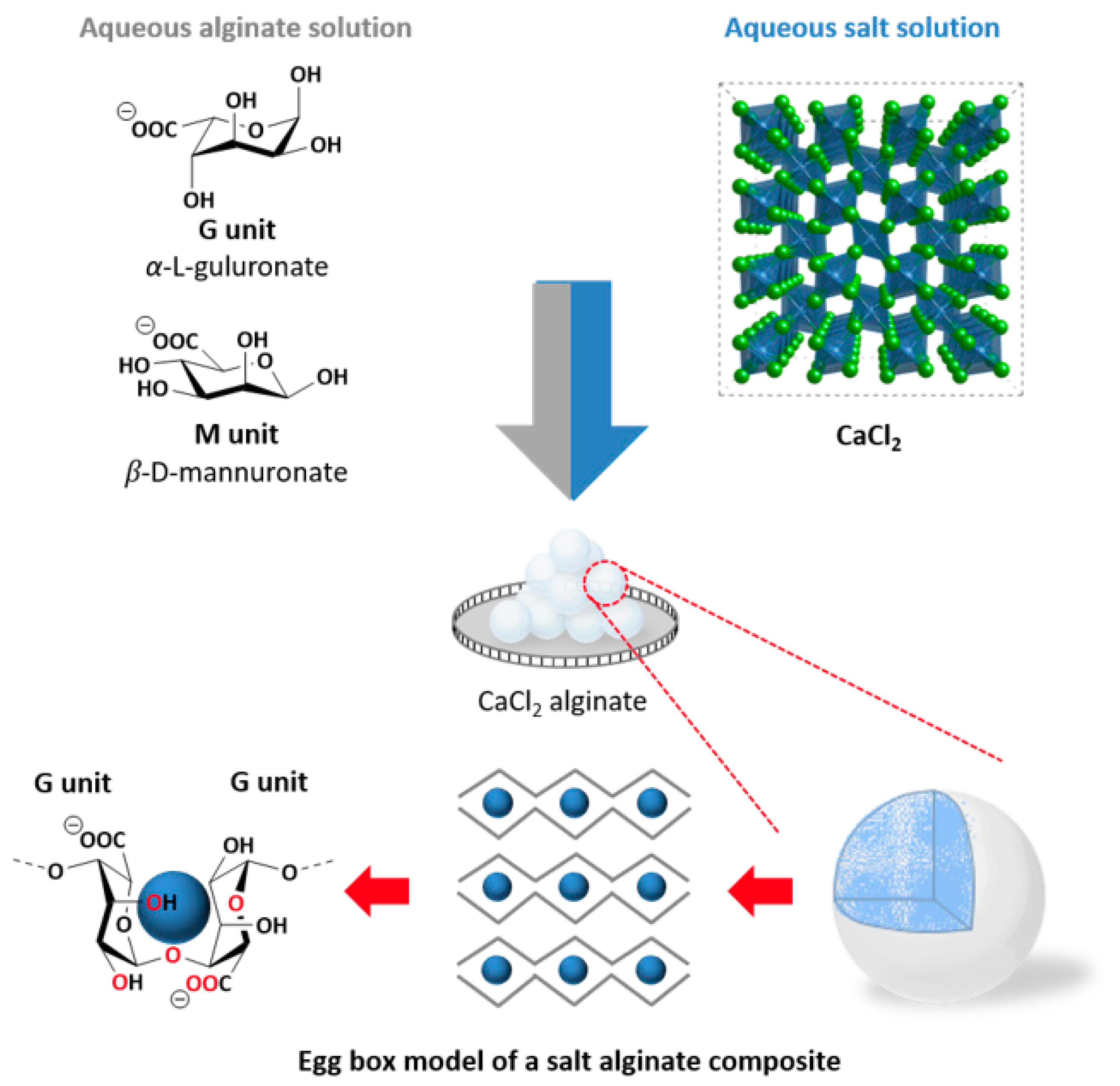
2.2. Preparation of the Calcium Chloride Alginate Composite

For the CaCl2 composite, a homogeneous mixture of water (3.2 L) and sodium alginate (64 g) was added dropwise to an aqueous solution of calcium chloride (4.64 kg CaCl2 and 6.4 L water) via a funnel with a tap. The aqueous CaCl2 solution was filtered for purification prior to the dropping procedure (filter: Macherey-Nagel, MN615 ¼, Ø = 320 mm, REF 531 032). During the dropping process (gravity, rt, 250 rpm), agglomeration of the calcium alginate beads was prevented by stirring the salt solution and locating the droplet site outside the stirring vortex. The CaCl2 alginate beads were left covered in the salt solution for 24 h, decanted and filtrated, washed with 1.25 L water four times and finally dried via a two-step procedure: (1) rotary evaporation (90 °C, 150 mbar) for 2 h; (2) storage in an oven for 30 h at 140 °C. An average of 135 to 160 g of calcium alginate beads per batch was obtained via this synthesis process. Figure 1 shows a graphical summary of the synthesis pathway and the processes involved.

2.3. Characterization of the Material

The chloride content of the composite material was determined by ion chromatography (IC) on an aqueous eluate. From this, conclusions have then been made regarding the salt content of the storage material. The porosity ϕ of the materials used is determined according to the relationship between bulk density ρ and pure density ρ0, expressed in Equation (1).
ϕ = ρ/ρ0,
The pure density was determined using a helium pycnometer of the type “AccuPyc 1330” from “Micromeritics” according to the DIN 66137-2 standard [25]. For this purpose, the storage material was dried at 130 °C for 24 h, finely ground, dried again at 130 °C for 24 h, and measured. The bulk density is determined by means of a geopycnometer of the type “Geopyk 1360” from the company “Micromeritics”. In this method, the bulk density is determined by displacing a solid medium, dry flow. This medium formed a dense packing around the object to be examined without penetrating into the pore spaces. By means of nitrogen adsorption, the specific surface area was determined by the Brunauer, Emmett and Teller (BET) method in a “SA 3100” from the company “Coulter” according to the DIN ISO 9277:2014-01standard [26]. In addition, investigations in an “Autopore IV” mercury porosimeter from “Micromeritics” provided data on pore size distribution, porosity, surface area and mean pore diameter using the ISO 15901-1:2019-03 standard [27]. The storage material was dried in a drying oven at 130 °C for 24 h prior to each test. All IC, pycnometry, MIP and nitrogen adsorption measurements were performed in triplicate. Scanning electron microscope (SEM) images were taken of the raw material as well as after 5, 10 and 15 cycles on a “Hitachi TM3000, Bruker EDX” of some of the particles to visualize possible changes.

2.4. Calorimetric Investigations

The heat release generated by the reaction of the material with water was recorded in a “C80” calorimeter combined with a wet air generator “Wetsys” from “Setaram Instrumentation”. For this purpose, the samples (approximately 50 mg) were heated to a temperature of 130 °C (at 2 K/min) in a reaction cell, while the chamber was purged with a constant volume flow (50 mL/min) of dry nitrogen. At this temperature, the sample can dehydrate well; it can be easily reached with solar thermal systems, and the alginate matrix can withstand it without any problems [24,28]. After a holding time of 2 h, the temperature was lowered to 25 °C at 0.22 K/min; the volume flow of nitrogen remained unchanged. After reaching 25 °C and setting a constant heat flux, the relative humidity was abruptly increased to 20 and 30% RH, respectively. This range between the transition calcium chloride tetrahydrate (CaCl2∙4H2O)/hexahydrate (CaCl2∙6H2O) and the deliquescence line of calcium chloride hexahydrate should ensure that the formation of calcium chloride hexahydrate occurs and no washing out due to solution formation appears [24,29]. Integrating the curve of the heat flux when the material is loaded provides the total heat released from the reaction, i.e., the heat of hydration.

2.5. Thermogravimetry

To determine the amount of water absorbed, the samples were dehydrated in a thermogravimetry following the calorimetry. Previous studies on dehydration of similar composites have shown that CaCl2∙2H2O can be found at temperatures above 75 °C and CaCl2 anhydrate at temperatures above 120 °C [24]. For this purpose, the samples were heated to 130 °C under inert gas and the change in mass was recorded. A simultaneous thermal analysis apparatus “STA 449 F3 Jupiter” from “Netsch” was used.

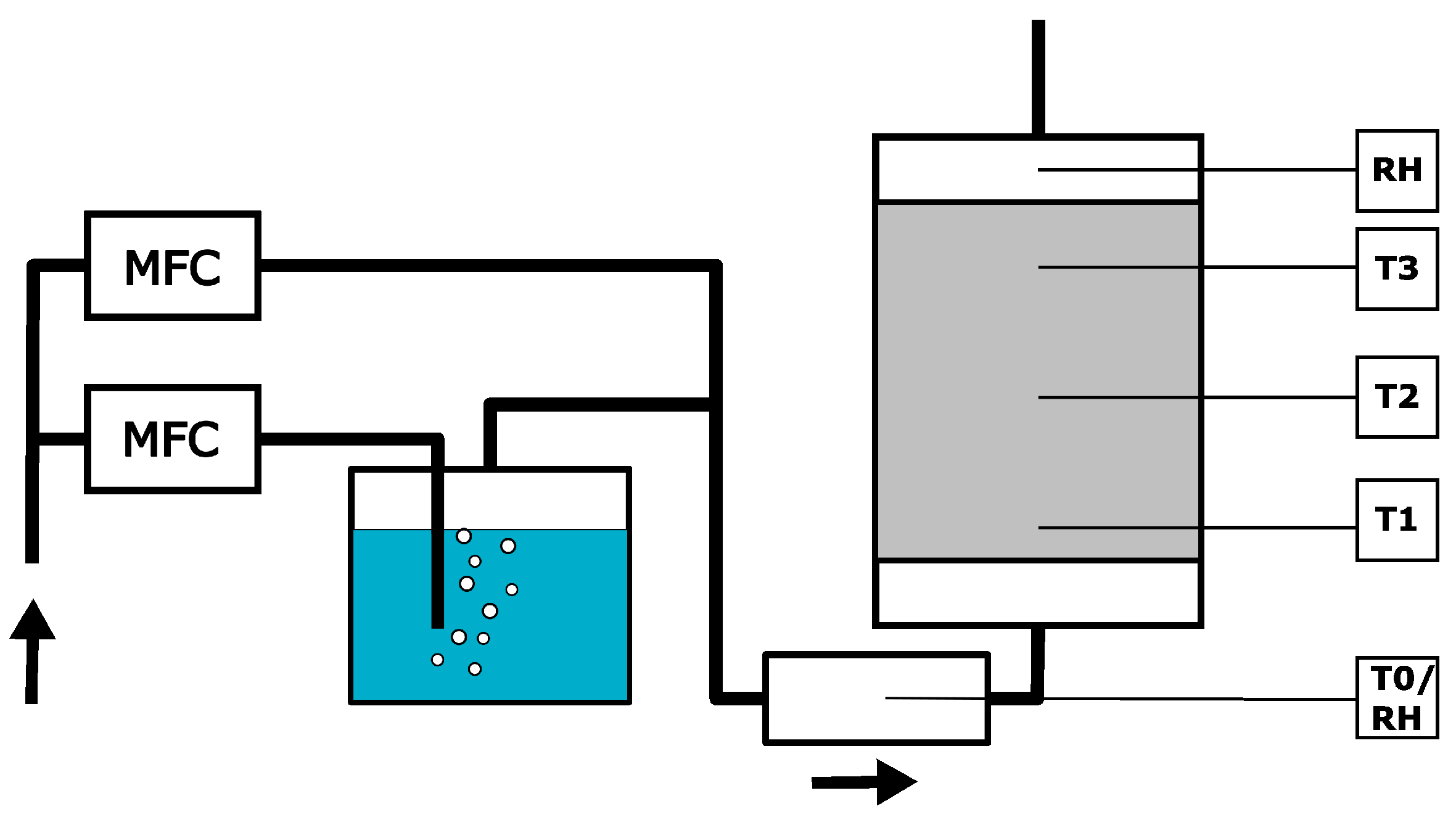
2.6. Experiments in a 1 L Reactor

To investigate the temperature rise of the material in a reactor bed, a laboratory reactor with a capacity of 1 L was designed and constructed. A sketch of the experimental setup with humid air generation and reactor chamber, as well as sensors for measuring temperature and relative humidity, is shown in Figure 2. This is an open-reactor system in which a constant flow of humid air passes through the storage material from below. A cylindrical stainless-steel chamber with a diameter of 101 mm and a height of 155 mm formed the reaction chamber. At the inlet and outlet, the chamber was tapered to 19 mm, which also corresponded to the diameter of the air duct. The storage material was held in place by a stainless-steel mesh screen and the entire system was thermally insulated with a 20 mm fiberglass mat. The humid air was generated by means of two mass flow controllers (MFC), one that controlled dry air and one that controlled the flow of humid air via a bubbler; back pressure valves secured the MFCs. These two air streams were merged, whereupon the humidity and temperature were measured for the first time in a chamber in front of the reactor vessel. This chamber and the area directly below the particle bed were intended to ensure that the airflow was homogeneously mixed and uniform. A second humidity sensor was placed behind the particle bed. The humidity sensors used were “DMTHM8XX” from the company “DM-Sensors”; the temperature sensors in the particle bed were common sheathed thermocouples of type K. An amount of 599 g of composite material was examined, which was dehydrated in a drying oven at 130 °C for 24 h prior to performing the experiment. It was then cooled to room temperature in desiccators and afterwards transferred to the reactor chamber. The temperature of the incoming air depended on the ambient conditions and ranged between 20 and 23 °C. The water content of the air used was between 20 and 23% RH at a volume flow of 10 L/min. Temperatures were recorded over a course of 65 h, and a total of fifteen (energetic) discharge cycles were performed and recorded. After the fifth, tenth and fifteenth cycles, a few grams of material were taken in each case to analyze any changes in the material.

3. Results and Discussion

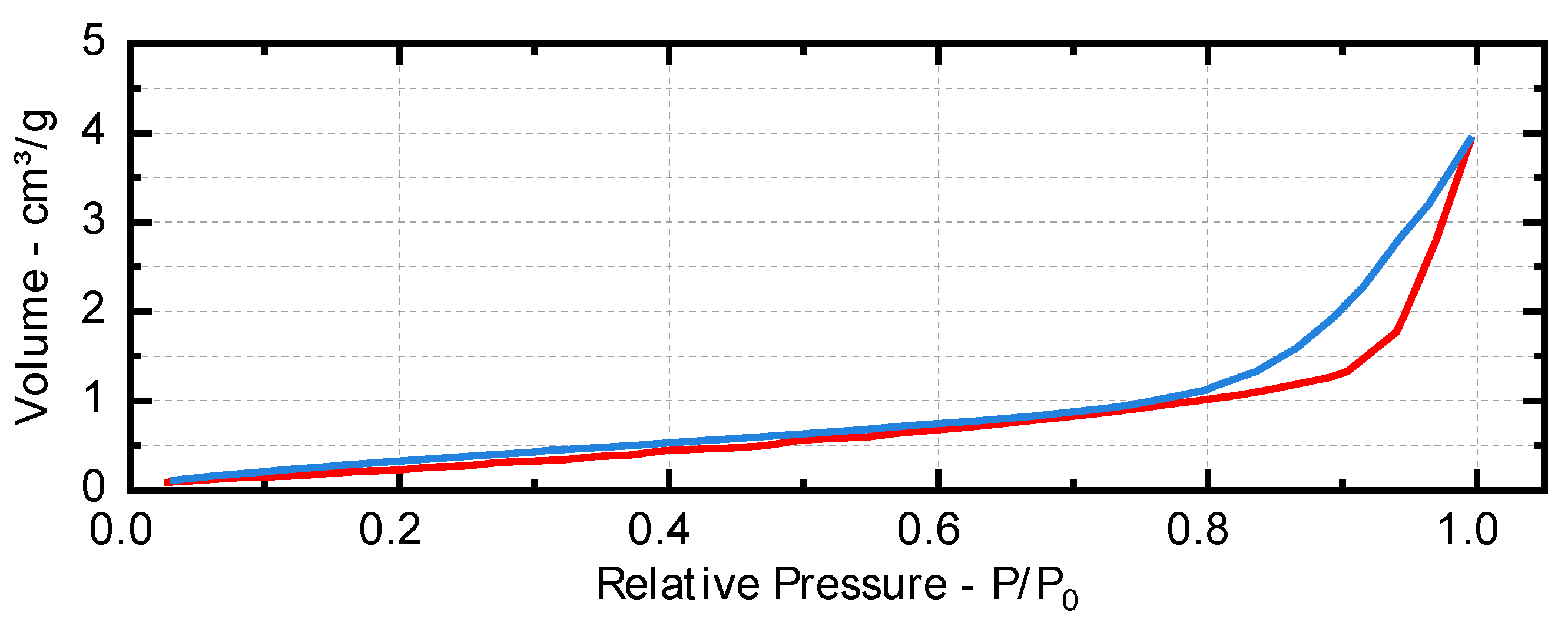
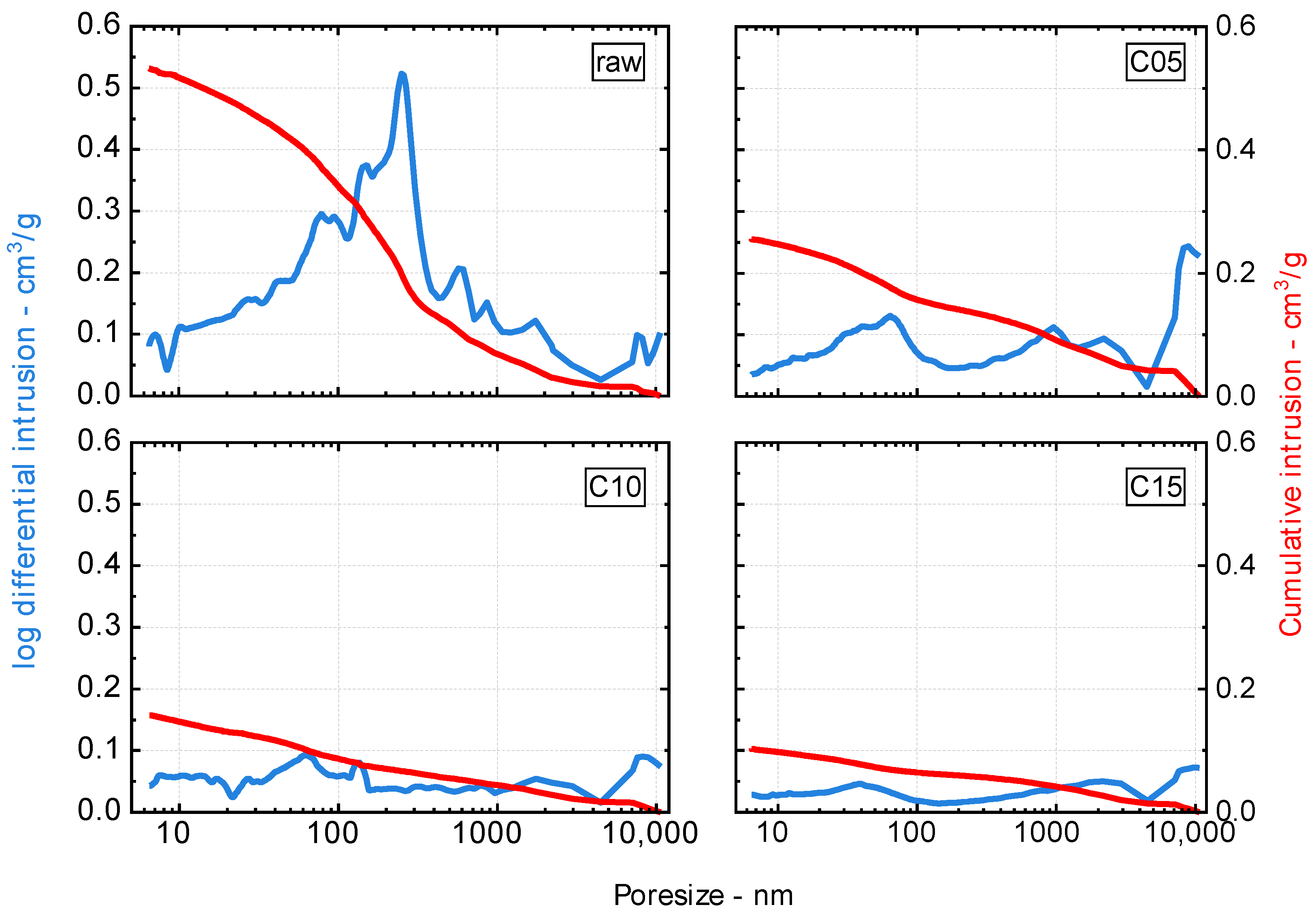
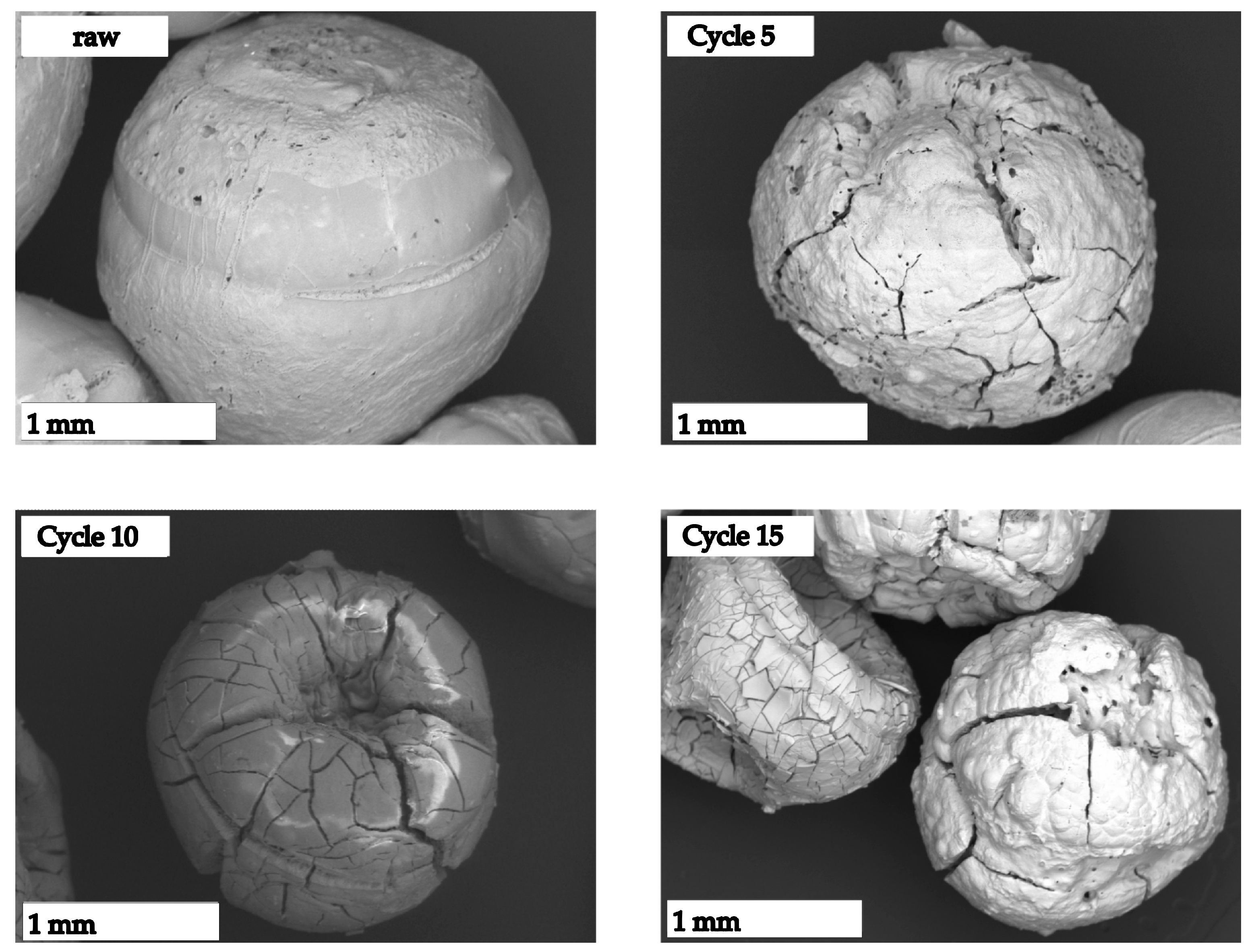
3.1. Material Properties

The values determined by ion chromatography, mercury intrusion porosimetry (MIP), nitrogen adsorption and pycnometry are shown in Table 1. The chloride content was determined by ion chromatography at 44.1 wt%, suggesting a maximum CaCl2 mass fraction of 69 wt%. The average pore diameter dav, total porosity ϕMIP and specific surface area SMIP were determined via MIP. The bulk density ρ was determined via a geo-pycnometer and the pure density ρ0 via helium adsorption. The determined bulk density of the MIP with 0.96 g/cm3 confirms the determined value of ρ0. The calculated total porosity ϕcal of 53% was compared with the open porosity of the MIP ϕMIP of 28%. This resulted in a closed porosity of 25% in a pore range > 6 nm. The value of the specific surface area, which was determined by the BET method from the isotherms of the nitrogen sorption, is not meaningful, since the isotherm suggests that the proportion of micro- and mesopores is extremely low. Figure 3 shows the adsorption and desorption isotherms of nitrogen adsorption of the untreated CaCl2 alginate particles. This assumption is confirmed by MIP measurements, shown in Figure 4 top left, where 79% of the samples were determined to be macroporous. Therefore, the value of the specific surface area determined by MIP seems to be more accurate, despite the assumption of a cylindrical mantle surface [30,31]. In addition, Figure 4 also shows the pore size distribution determined by MIP after cycles five, ten and fifteen.
Evaluations of MIP over the course of 15 cycles show a very strong decrease in the pores in all size ranges. After five cycles, for example, it can be observed that the large proportion of pores in the 250 nm range has disappeared, and a far more homogeneous distribution of pore sizes has occurred. Looking at the next ten cycles, a much less significant decrease in pore size is observed, but the total volume of pores has decreased from 0.53 cm3/g to 0.1 cm3/g. As a result, the densities determined no longer conform to the raw densities determined by pycnometry. In this case, the density of the MIP is considered inaccurate since the calculation basis for the density is also lost as a result of the disappearance of the pore space, and this also applies to the specific surface area and porosity values. This disappearance of pores can be attributed to the density and concomitant volume change from non-hydrated CaCl2 to calcium chloride hexa- and tetrahydrate (CaCl2∙6H2O; CaCl2∙4H2O) as well as solution formation [18]. Images taken with the scanning electron microscope illustrate this in Figure 5. Here, the growing crack structures are clearly visible, which can be attributed to the expansion during water absorption and contraction during drying. In combination with these crack formations, density changes that peak after the 10th cycle at ρ = 1.21 and result in a porosity change to ϕcal = 40% can be observed. After 15 cycles, these values decrease to ρ = 1.09, resulting in a porosity of ϕcal = 45%. Accompanied by this, a decrease in the specific surface area can be observed. The effects of the changing material parameters can be seen above all in the following subsections.

3.2. Calorimetry

The key feature of a heat storage material, the energy storage density, is determined by calorimetric investigations. The results are presented in Table 2 along with the literature values. The determined values refer to the consideration of the materials as a packed bed, as indicated by the authors. The material used is similar to that of Kallenberger except for the salt content, which in his case is between 80 and 90 wt%; in contrast, the value determined for the material studied here is 69 wt%. The salt contents of Kallenberger refer to the lowest available hydrate grade, and the salt content of this work refers to pure salt. To ensure the optimal energy yield and an almost compact material, it is desirable to reach the hydrate stage of CaCl2 6H2O without any formation of solution. This requires safe handling of temperature and humidity since the melting temperature of hexahydrate is about 25 °C at humidities of about 30% RH [32]. The selected parameters of 25 °C and 20% RH are intended to ensure that the optimum energy yield is achieved without solution formation [29,32,33]. The determined storage densities of the raw material of 1.28 kJ/cm3 and 1.39 kJ/cm3 are in the range of those of a similar composite material reported by the literature at 1.50 kJ/cm3 and 1.10 kJ/cm3 [24] and exceed those of storage materials with vermiculite as carrier with 1.2 kJ/cm3 [22]. Although, in the reported material there was dissolution or no formation of the CaCl2 hexahydrate [22,24]. As the number of cycles increases and the material parameters change, in particular porosity and density, an increase in the heat of hydration can be detected. Especially in the experiments with a humidity of 30% RH, an increase of up to 0.84 kJ/cm3 has been analyzed, same as the values of the experiments with lower humidity which also show an increase in hydration heat. In combination with the density changes of the material, the energy storage density thus also increases to its maximum at 2.11 kJ/cm3 at 25 °C and 20% RH and 2.23 kJ/cm3 at 25 °C and 30% RH after the fifteenth cycle.

3.3. Thermogravimetry

The samples loaded in the calorimeter were promptly examined thermogravimetrically after the measurement to determine the amount of water absorbed. The amount of water absorbed during loading can be used to draw conclusions about the hydrate levels in the composite. Thermogravimetric analysis of the material loaded at 25 °C and 20% RH showed a mass loss of 24% and thus a water content of 0.35 gH2O/gsample dry. Assuming that the salt was not hydrated at the beginning of the experiment, this amount would not be enough to completely convert the salt present into the hexahydrate. Thus, it must be assumed that only part of the salt participated in the reaction. Looking at later cycles, it is noticeable that with a slight increase in water uptake, significantly more heat energy is released, so that after 15 cycles the water uptake has increased to 0.47 gH2O/sample dry while the heat yield increased considerably from 1.28 to 2.11 kJ/cm3. This increase in water adsorption is due to the formation of cracks and the “opening” of the pores, which were discussed in Section 3.1. When looking at the material loaded at 30% RH, it is noticeable that the water absorption decreases from 0.64 to 0.48 gH2O/sample dry (after 10 cycles even to 0.32 gH2O/sample dry). This may be related to the disappearance of the small pores; it is possible that part of the water in the raw material is not stored as hydrate water but in capillary pores. Because these account for a smaller and smaller proportion as the number of cycles increases, and at the same time more and more salt becomes accessible via crack formation, a lower or similar water absorption can lead to increased heat release. The lower water absorption compared to the literature value specimens may be due to the lower salt content, the other test parameters of temperature and humidity or a possibly different pore pattern. Exact statements on this cannot be made due to the lack of material parameters.

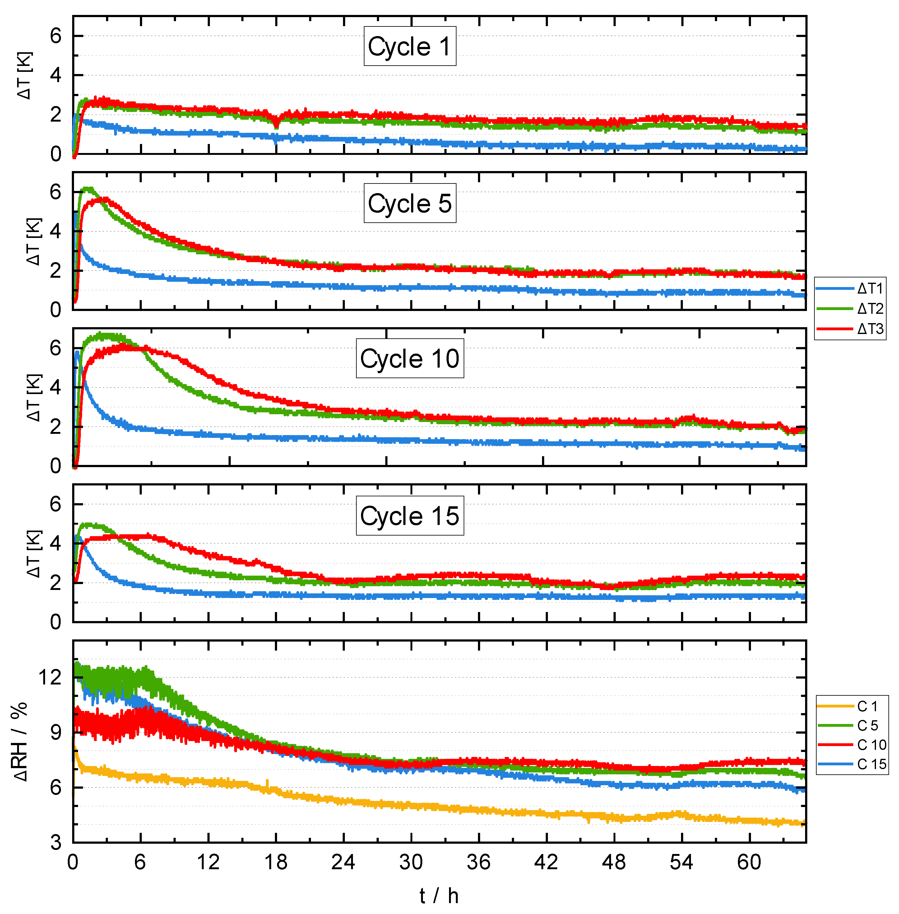
3.4. Reactor Experiments

The temperature gradients of the reactor tests after one, five, ten and fifteen cycles are shown in Figure 6, as are the differences in relative humidity between the inlet and outlet of the reactor chamber. When observing the first cycle, a small temperature deviation of 3 K can be seen, which increases over the period of ten cycles to a maximum of 6.5 K. In addition to the increase in the temperature deviation, a broadening of the temperature peak can be observed, i.e., a higher temperature yield with a constant amount of air fed in. From the tenth cycle on, a decrease in the temperature peak can be observed, which has decreased down to 5 K after the fifteenth cycle. The temperature and humidities of the incoming air were between 20 to 23 °C and 20 to 23% RH, respectively. The humidity difference between the incoming and outgoing air was 6% RH at the end of the experiment, indicating that loading was not yet complete at this point. Furthermore, from the difference in the water content of the air, it can be concluded that the uncycled material can absorb much less water than the storage materials of later cycles, which is finally evident in the increasing temperature yield. In addition to the amount of water absorbed, the reaction rate, i.e., the kinetics of the material, also increases as the number of cycles increases. These two findings are supported by the material properties collected and can be attributed to the “opening” of the pores and the rupturing of the particles, respectively. This leads to the water in the air reaching the salt inside more easily, thus hydrating it further to broaden and increase the temperature peaks, which eventually leads to a higher heat yield. For one application, this would mean an almost threefold temperature output over the course of 12 h, dropping to the value of 2 K in the following 12 h. Under these conditions, the maximum temperature swing is nevertheless a good 50% below the 12 to 21 K already reported [24] and a further 30% lower than the latest findings for alginate/graphite-CaCl2 composites [23]. In the latter, it was also taken into account that the salt goes into the solution. Although fusion of the particles was observed, no significant drawbacks were found during the five cycles. To achieve these temperatures with the material studied in this work, it would have to be accepted that the deliquescence line would be exceeded. In direct comparison with tested zeolite storage tanks, which operated at 40 to 60% RH, it is noticeable that the temperature range is also much lower here, although the CaCl2 alginates compounds operate at only one-third of the humidity [34,35].

4. Conclusions

Large amounts of a CaCl2 alginate composite for thermochemical heat storage were studied in a 1 L reactor. The temperature developments in this particle bed were studied over 15 cycles, and the changes in the material were detected. The material values around porosity, pore distribution, densities, energy storage density and water absorption were collected from the raw material as well as after five, ten and fifteen cycles. Explicit care was taken to avoid dissolution of the salt hydrate to avoid agglomeration and washing out of the salt.
An amount of 599 g of a CaCl2 composite material embedded in an alginate matrix with a salt content of 69 wt% was loaded into a cylindrical reactor chamber with humid air (20 to 23% RH; 20 to 23 °C) at a flow rate of 10 L/min. The temperature evolution during the reaction inside the reactor chamber as well as the changing porosities, densities, water absorption and heat of the reaction between cycles were determined. During loading, care was taken not to exceed the deliquescence moisture content of the CaCl2∙6H2O as well as CaCl2∙4H2O.
The untreated material had an open porosity of 28%, with 79% of the pores being macropores. The total volume of the pores decreased from 0.53 cm3/g to 0.1 cm3/g over 15 cycles and severe crack growth was observed on the particles, with no apparent loss of stability. This cracking goes along with an increase of the bulk density up to 1.09, a decrease of the porosity to 45% and a decrease of the specific surface area. However, as the cracking seems to lead to better accessibility of the salt inside the particles, the water absorption increases from 0.35 gH2O/gsample dry to 0.47 gH2O/gsample dry and results in higher energy storage densities of the composite. These energy storage densities were detected over the course of the cycles, and an increase from 1.28 kJ/cm3 (357 kWh/m3) to 2.11 kJ/cm3 (587 kWh/m could be determined. With further approximation and probable exceeding of the deliquescence moisture, even higher energy storage densities of 1.39 kJ/cm3 (387 kWh/m3) up to 2.23 kJ/cm3 (619 kWh/m3) could be obtained. In contrast to this, in some cases, a higher energy yield with lower water absorption of the storage material was analyzed. A possible explanation for this may be the storage of water in capillary pores, the number of which decreases after a few cycles. This issue needs to be examined in more detail. The simultaneous formation of cracks may mean that salt is easier to reach in the interior.
The investigations show that the storage material by no means exhibits stable properties over 15 cycles but that the energy storage density actually improves over the course of a few cycles. The mechanical stability is not strongly influenced by the investigated cycles. The number of cycles for mechanical stability to be influenced remains to be clarified, but other work in this area reports more than 100 cycles of the same material. The temperature lift is and remains small and further confirms the complications of seasonal heat storage based on CaCl2. However, the increase in heat storage capacity and, in particular, the sharply increasing temperature output as the number of cycles increases may be of interest to other salt-hydrate storage systems.

Supplementary Materials

The following supporting information can be downloaded at: https://www.mdpi.com/article/10.3390/thermo3040035/s1, calorimetric and thermogravimetric measurements of the calcium chloride alginate composite particles.

Author Contributions

Conceptualization, S.H.; methodology, S.H. and T.S.; validation, S.H.; formal analysis, S.H.; investigation, S.H.; resources, A.O.; data curation, S.H.; writing—original draft preparation, S.H. and T.S.; writing—review and editing, A.O. and M.F.; visualization, S.H. and T.S.; supervision, A.O.; project administration, A.O. and M.F.; funding acquisition, A.O. and M.F. All authors have read and agreed to the published version of the manuscript.

Funding

This research was funded by the BMBF (Bundesministerium für Bildung und Forschung), as part of the project AlgiTherm with the project number 03EK3060A-B.

Data Availability Statement

The data presented in this study are available in the present article and in the related Supplementary Materials.

Acknowledgments

We are grateful to our project partners from Hamburg, especially Steiger, and Jens Schneider (Bauhaus-Universität Weimar) for the helpful discussions. Furthermore, we acknowledge support for the publication costs by the Open Access Publication Fund of Bauhaus-Universität Weimar. A special thanks goes to our funder, the BMBF, who made the AlgiTherm project (03EK3060A-B) possible in the first place.

Conflicts of Interest

The funders had no role in the design of the study; in the collection, analyses, or interpretation of data; in the writing of the manuscript; or in the decision to publish the results.

Nomenclature

CCA-rawcalcium chloride alginate composite uncycled
CCA-CXXcalcium chloride alginate composite after XX cycles
CCA-Kcalcium chloride alginate composite uncycled of literature source [24]
davaverage pore diameter
RHrelative humidity
Sspecific surface area
Ttemperature
ttime
wCaCl2mass fraction of CaCl2
Greek symbols
ρbulk density
ρ0raw density
Φporosity
Subscrips
0Raw (0 cycles)
BETBrunauer-Emmett-Teller
calcalculated
MIPmercury intrusion porosimetry

References

  1. Energien-Statistik Arbeitsgruppe Erneuerbare. Erneuerbare Energien in Deutschland Daten zur Entwicklung im Jahr 2021. Available online: https://www.umweltbundesamt.de/publikationen/erneuerbare-energien-in-deutschland-0 (accessed on 29 September 2023).
  2. Imbery, F.; Friedrich, K.; Kaspar, F.; Fleckenstein, R.; Lengefeld, K.; Bissolli, P.; Daßler, J. Klimatologische Einordnung des Jahres 2021. Available online: https://www.dwd.de/DE/klimaumwelt/aktuelle_meldungen/220105/deutschland_klimarueckblick_2021.html (accessed on 29 September 2023).
  3. Rundel, P.; Meyer, B.; Meiller, M.; Meyer, I.; Daschner, R.; Jakuttis, M.; Franke, M.; Binder, S.; Hornung, A. Studie Speicher fuer die Energiewende. Sulzbach-Rosenberg. 2013. Available online: https://www.umsicht-suro.fraunhofer.de/content/dam/umsicht-suro/de/documents/studien/studie_speicher_energiewende.pdf (accessed on 29 September 2023).
  4. Mette, B.; Kerskes, H.; Drück, H.; Müller-Steinhagen, H. Experimental and numerical investigations on the water vapor adsorption isotherms and kinetics of binderless zeolite 13X. Int. J. Heat. Mass. Transf. 2014, 71, 555–561. [Google Scholar] [CrossRef]
  5. Núñez, T.; Mittelbach, W.; Henning, H.-M. Development of an adsorption chiller and heat pump for domestic heating and air-conditioning applications. Appl. Therm. Eng. 2007, 27, 2205–2212. [Google Scholar] [CrossRef]
  6. Kaneko, K. Micropore filling mechanism in inorganic sorbents. Stud. Surf. Sci. Catal. 1996, 99, 573–598. [Google Scholar] [CrossRef]
  7. N’Tsoukpoe, K.E.; Liu, H.; Le Pierrès, N.; Luo, L. A review on long-term sorption solar energy storage. Renew. Sustain. Energy Rev. 2009, 13, 2385–2396. [Google Scholar] [CrossRef]
  8. N’Tsoukpoe, K.E.; Schmidt, T.; Rammelberg, H.U.; Watts, B.A.; Ruck, W.K.L. A systematic multi-step screening of numerous salt hydrates for low temperature thermochemical energy storage. Appl. Energy 2014, 124, 1–16. [Google Scholar] [CrossRef]
  9. Aristov, Y.I.; Tokarev, M.M.; Cacciola, G.; Restuccia, G. Selective water sorbents for multiple applications, 1. CaCl2 confined in mesopores of silica gel: Sorption properties. React. Kinet. Catal. Lett. 1996, 59, 325–333. [Google Scholar] [CrossRef]
  10. Jänchen, J.; Ackermann, D.; Weiler, E.; Stach, H.; Brösicke, W. Calorimetric investigation on zeolites, AlPO4’s and CaCl2 impregnated attapulgite for thermochemical storage of heat. Thermochim. Acta 2005, 434, 37–41. [Google Scholar] [CrossRef]
  11. Tso, C.Y.; Chao, C.Y.H. Activated carbon, silica-gel and calcium chloride composite adsorbents for energy efficient solar adsorption cooling and dehumidification systems. Int. J. Refrig. 2012, 35, 1626–1638. [Google Scholar] [CrossRef]
  12. van Essen, V.M.; Zondag, H.A.; Gores, J.C.; Bleijendaal, L.P.J.; Bakker, M.; Schuitema, R.; van Helden, W.G.J.; He, Z.; Rindt, C.C.M. Characterization of MgSO4 Hydrate for Thermochemical Seasonal Heat Storage. J. Sol. Energy Eng. 2009, 131, 4. [Google Scholar] [CrossRef]
  13. Posern, K.; Kaps, C. Humidity controlled calorimetric investigation of the hydration of MgSO4 hydrates. J. Therm. Anal. Calorim. 2008, 92, 905–909. [Google Scholar] [CrossRef]
  14. Posern, K.; Kaps, C. Calorimetric studies of thermochemical heat storage materials based on mixtures of MgSO4 and MgCl2. Thermochim. Acta 2010, 502, 73–76. [Google Scholar] [CrossRef]
  15. Ferchaud, C.J.; Zondag, H.A.; de Boer, R. Material Research on Salt Hydrates for Seasonal Heat Storage Application in a Residential Environment. In Proceedings of the International Symposium on Innovative Materials for Processes in Energy System (IMPRESS 2013), Fukuoka, Japan, 4–6 September 2013. [Google Scholar]
  16. van Essen, V.M.; Cot Gores, J.; Bleijendaal, L.P.J.; Zondag, H.A.; Schuitema, R.; Bakker, M.; van Helden, W.G.J. Characterization of Salt Hydrates for Compact Seasonal Thermochemical Storage. In Proceedings of the ASME 2009 3rd International Conference on Energy Sustainability collocated with the Heat Transfer and InterPACK09 Conferences, San Francisco, CA, USA, 19–23 July 2009; ASMEDC: Houston, TX, USA, 2009; Volume 2, pp. 825–826. [Google Scholar]
  17. Steiger, M. Thermodynamic properties of SrCl2(aq) from 252 K to 524 K and phase equilibria in the SrCl2–H2O system: Implications for thermochemical heat storage. J. Chem. Thermodyn. 2018, 120, 106–115. [Google Scholar] [CrossRef]
  18. N’Tsoukpoe, K.E.; Rammelberg, H.U.; Lele, A.F.; Korhammer, K.; Watts, B.A.; Schmidt, T.; Ruck, W.K.L. A review on the use of calcium chloride in applied thermal engineering. Appl. Therm. Eng. 2015, 75, 513–531. [Google Scholar] [CrossRef]
  19. Gordeeva, L.G.; Restuccia, G.; Freni, A.; Aristov, Y.I. Water sorption on composites “LiBr in a porous carbon”. Fuel Process. Technol. 2002, 79, 225–231. [Google Scholar] [CrossRef]
  20. Simonova, I.A.; Freni, A.; Restuccia, G.; Aristov, Y.I. Water sorption on composite “silica modified by calcium nitrate”. Microporous Mesoporous Mater. 2009, 122, 223–228. [Google Scholar] [CrossRef]
  21. Gordeeva, L.G.; Tokarev, M.M.; Parmon, V.N.; Aristov, Y.I. Selective water sorbents for multiple application, 6. Freshwater production from the atmosphere. React. Kinet. Catal. Lett. 1998, 65, 153–159. [Google Scholar] [CrossRef]
  22. Gaeini, M.; Rouws, A.L.; Salari, J.W.O.; Zondag, H.A.; Rindt, C.C.M. Characterization of microencapsulated and impregnated porous host materials based on calcium chloride for thermochemical energy storage. Appl. Energy 2018, 212, 1165–1177. [Google Scholar] [CrossRef]
  23. Reynolds, J.; Williams, R.; Elvins, J.; Jewell, E.; Searle, J.; Ke, X. Development and characterisation of an alginate and expanded graphite based composite for thermochemical heat storage. J. Mater. Sci. 2023, 58, 5610–5624. [Google Scholar] [CrossRef]
  24. Kallenberger, P.A.; Posern, K.; Linnow, K.; Brieler, F.J.; Steiger, M.; Fröba, M. Alginate-Derived Salt/Polymer Composites for Thermochemical Heat Storage. Adv. Sustain. Syst. 2018, 2, 1700160. [Google Scholar] [CrossRef]
  25. DIN 66137-2: 2019-03; Bestimmung der Dichte fester Stoffe_-Teil_2: Gaspyknometrie. Beuth Verlag GmbH: Berlin, Germany, 2019.
  26. DIN ISO 9277:2014-01; Bestimmung der spezifischen Oberfläche von Festkörpern mittels Gasadsorption_-BET-Verfahren (ISO_9277:2010). Beuth Verlag GmbH: Berlin, Germany, 2014.
  27. DIN ISO 15901-1: 2019-03; Bewertung der Porengrößenverteilung und Porosität von Feststoffen mittels Quecksilberporosimetrie und Gasadsorption_- Teil_1: Quecksilberporosimetrie (ISO_15901-1:2016). Beuth Verlag GmbH: Berlin, Germany, 2019.
  28. Stach, H.; Mugele, J.; Jänchen, J.; Weiler, E. Influence of Cycle Temperatures on the Thermochemical Heat Storage Densities in the Systems Water/Microporous and Water/Mesoporous Adsorbents. Adsorption 2005, 11, 393–404. [Google Scholar] [CrossRef]
  29. Pátek, J.; Klomfar, J.; Součková, M. Solid−Liquid Equilibrium in the System of CaCl2 −H2O with Special Regard to the Transition Points. J. Chem. Eng. Data 2008, 53, 2260–2271. [Google Scholar] [CrossRef]
  30. Rouquerol, J.; Avnir, D.; Fairbridge, C.W.; Everett, D.H.; Haynes, J.M.; Pernicone, N.; Ramsay, J.D.F.; Sing, K.S.W.; Unger, K.K. Recommendations for the characterization of porous solids (Technical Report). Pure Appl. Chem. 1994, 66, 1739–1758. [Google Scholar] [CrossRef]
  31. Barrett, E.P.; Joyner, L.G.; Halenda, P.P. The Determination of Pore Volume and Area Distributions in Porous Substances. I. Computations from Nitrogen Isotherms. J. Am. Chem. Soc. 1951, 73, 373–380. [Google Scholar] [CrossRef]
  32. Simon, T.; Dohrmann, M.; Steiger, M.; Fröba, M. Calcium Chloride Alginate Composites as Thermochemical Heat Storage Media and the Influence of Different Alginate Species on the Behavior of the Composites. in preperation.
  33. Carlsson, B.; Stymne, H.; Wettermark, G. An incongruent heat-of-fusion system—CaCl2·6H2O—Made congruent through modification of the chemical composition of the system. Sol. Energy 1979, 23, 343–350. [Google Scholar] [CrossRef]
  34. Kerskes, H.; Mette, B.; Bertsch, F.; Asenbeck, S.; Drück, H. Chemical energy storage using reversible solid/gas-reactions (CWS—Results of the research project. Energy Procedia 2012, 30, 294–304. [Google Scholar] [CrossRef]
  35. Kerskes, H.; Sommer, K.; Müller-Steinhagen, H.M. Final Report: Integrales Konzept zur solarthermischen Gebäudeheizung mit Sorptionswärmespeicher. MonoSorp (BWK25006). Stuttgart. 2007. Available online: https://pudi.lubw.de/detailseite/-/publication/77219-Monosorp_-_Integrales_Konzept_zur_solarthermischen_Geb%C3%A4udeheizung_mit_Sorptionsw%C3%A4rmespeicher.pdf (accessed on 29 August 2023).
Figure 1. Illustration of the synthesis pathway used for the CaCl2 alginate composites. The white beads represent the CaCl2 alginate composites, and the blue beads represent the Ca2+ cations responsible for cross-linking the alginate matrix. Egg box model: coordination of the Ca2+ cations by the atoms marked in red.
Thermo 03 00035 g001
Figure 2. Drawing of the experimental setup with the moist air generation on the left and the reactor chamber on the right with four measuring points for temperature (T) and two for relative humidity (RH). The arrow describes the flow direction of the air, and the flow rate is adjusted by two mass flow controllers (MFCs).
Thermo 03 00035 g002
Figure 3. Adsorption (red) and desorption (blue) isotherm of nitrogen adsorption of the uncyclized material.
Thermo 03 00035 g003
Figure 4. Mercury intrusion porosimetry of the raw storage material and after 5, 10 and 15 cycles. The log differential intrusion is the blue line; the cumulative intrusion is the red line.
Thermo 03 00035 g004
Figure 5. SEM images of representative particles of the raw material and after 5, 10 and 15 cycles passed.
Thermo 03 00035 g005
Figure 6. Temperature lift of a laboratory reactor filled with 599 g CaCl2-alginate particles. The temperature lift is represented by three temperature differences from the bottom (∆T1) to the top (∆T3). In addition, the differences in humidity between incoming and outgoing air are shown. The temperatures of the tests were between 20 and 23 °C, and the humidity values were between 20 and 23% RH.
Thermo 03 00035 g006
Table 1. Material properties of the composite determined by ion chromatography (weight percentage of calcium chloride wCaCl2), pycnometry (pure density ρ0, bulk density ρ), nitrogen adsorption (specific surface area SBET) and MIP (bulk density ρMIP, porosity ϕMIP, specific surface area SMIP, average pore diameter dav). The porosity ϕcal was calculated using Equation (1).
CyclewCaCl2
(wt%)
ρ0
(g/cm3)
ρ
(g/cm3)
ρMIP
(g/cm3)
ϕMIP (%)ϕcal (%)SBET (m2/g)SMIP
(m2/g)
dav
(nm)
raw69.02.000.970.9628531.43661
5--0.860.8414571.11760
10--1.211.5214401.01543
15--1.091.5710451.0852
Table 2. Results of the calorimetric and thermogravimetric investigations of the raw storage material and after 5, 10 and 15 cycles of hydration and dehydration. The storage densities are calculated with the density ρ and the measured heat of reaction. The water absorption refers to the dry storage material.
Temperature [°C]/
Relative Humidity [%]
Heat of Reaction [kJ/kg]Storage Density
[kJ/cm³] ([kWh/m³])
Water Uptake
[gH2O/gsample dry]
CCA-raw25/2013241.28 (357)0.35
25/3014781.39 (387)0.64
CCA-C0525/2013431.13 (313)0.39
25/3017901.50 (418)0.61
CCA-C1025/2010361.57 (437)0.33
25/3012711.93 (537)0.32
CCA-C1525/2013472.11 (587)0.47
25/3014192.23 (619)0.48
CCA-K [24]30/2010181.10 (306)0.64
30/3012061.50 (417)0.88
Disclaimer/Publisher’s Note: The statements, opinions and data contained in all publications are solely those of the individual author(s) and contributor(s) and not of MDPI and/or the editor(s). MDPI and/or the editor(s) disclaim responsibility for any injury to people or property resulting from any ideas, methods, instructions or products referred to in the content.

