1. Introduction
Enhancing heat transfer systems can lead to direct and indirect improvements in numerous devices and systems, ultimately helping to reduce greenhouse gas emissions. In this context, small-diameter tube bundle heat exchangers play an essential role, providing better drainage systems, reduced refrigerant charge amounts, and cost-effective solutions for industrial energy plants, air conditioning systems, manufacturing processes, transportation systems, and information systems worldwide [
1].
Heat exchangers, which are essential components in many engineering applications, facilitate the transfer of thermal energy between two or more fluids at different temperatures. The performance of a heat exchanger is influenced by various factors, including the geometry of the tubes, the type of fluid used, and the flow regime (laminar or turbulent). In recent years, considerable research has been directed toward improving the efficiency and compactness of heat exchangers, leading to the development of novel designs and advanced materials. Among these innovations, small-diameter tube bundle heat exchangers have attracted significant attention because of their potential for high thermal performance and reduced material usage.
Many studies have already been conducted to design and augment heat exchangers with tube bundles. Early investigations by Chilton and Genereaux, 1933 [
2] examined existing data on pressure drops across tube banks and recalculated the data, proposing correlations for both staggered and inline tube bundles. A common approach to improve the heat transfer of a tube bundle is to increase the heat transfer area by introducing various types of fins, such as plain fins [
3], wavy fins [
4], louvred fins [
5,
6,
7], and offset fins [
8], in addition to the tube bundle. The addition of fins serves to increase the surface area available for heat transfer to enhance overall heat transfer. Furthermore, the use of different fin geometries and configurations can lead to improvements in both heat transfer and pressure drop performance, ultimately resulting in a more efficient heat exchanger design.
Computational fluid dynamics (CFD) simulations have become essential tools for the analysis and design of heat exchangers, including small-diameter tube bundle heat exchangers. Using commercial software, such as ANSYS FLUENT 2021 R2, the complex fluid flow and heat transfer phenomena that occur in these systems can be observed and predicted.
Sun et al. [
9], who investigated the heat transfer and fluid flow characteristics of a small-diameter fin-and-tube heat exchanger, conducted a notable study using simulations. They proposed a condenser model for simulations to analyze the effects of various fin geometries, tube arrangements, and flow conditions on the heat transfer performance and pressure drop characteristics of heat exchangers. Their findings revealed that optimizing the fin geometry and tube arrangement could significantly enhance heat transfer performance while maintaining acceptable pressure drop levels.
Another study by Liu et al. [
10] used ANSYS FLUENT commercial simulation software to examine the performance of a microchannel heat exchanger with small-diameter tubes. They used a k-ε realizable model (RKE) in their simulation. They analyzed different tube configurations and fin types, including plain fins, wavy fins, and louvered fins, to determine their impacts on heat transfer and pressure drop performance. The results of their simulations revealed that the optimal configuration depended on the specific application and operating conditions, highlighting the importance of using simulations in the design process.
In a more recent study, Lim and Park [
11] used simulations to investigate the thermal-hydraulic performance of a small-diameter tube bundle heat exchanger with novel twisted tape inserts. The twisted tape inserts were found to induce swirl flow within the tubes, significantly enhancing the heat transfer coefficient and overall performance of the heat exchanger. Their CFD simulations also helped identify optimal twisted tape geometries and configurations for various applications.
Furthermore, Abdelaziz et al. [
12] developed a methodology called the parallel parameterized method using a multiscale HX simulation approach, which automated CFD runs for a given parameterized geometry. This approach significantly reduced the engineering time required to complete the simulations and post processing, allowing for a more efficient exploration of design options.
Paitoonsurikarn et al. [
13] proposed a bare-tube micro heat exchanger without conventional fins as an alternative to conventional oversized-diameter tube fin heat exchangers. Their study demonstrated that the bare-tube micro heat exchanger had the potential to improve heat transfer performance and compactness. The key advantage of this design lay in its ability to achieve high heat transfer rates with a smaller hydraulic diameter, which reduced the overall size of the heat exchanger and decreased the amount of material required for construction. Furthermore, the reduced hydraulic diameter promoted turbulent flow, improving the heat transfer coefficient and the overall performance of the heat exchanger.
Previous correlations have been reported for single tubes with diameters greater than 9 mm in the literature. Huge [
14] and Pierson [
15] were the first to present correlated experimental data on heat exchangers involving air-to-refrigerant heat transfer. Žukauskas [
16] further studied the friction and heat transfer properties of different arrangements for tube bundles using different fluids. Various data [
16] were presented and may be the most commonly used for bare-tube thermal exchanges so far. Some theoretical correlations for bare tubes are also available in the literature by Khan et al. [
17]. However, simple fin and tube geometries have a greater number of correlations. McQuiston [
18] proposed the first correlation of this application in 1978, which was later improved by Gray and Webb [
19]. The most recent correlations for plate-and-fin tubes are those of Wang and Chi [
3]
More recently, Bacellar et al. [
20] investigated various geometries for small-diameter bare tubes and presented air-side heat transfer and pressure drop correlations based on simulation results. Their study demonstrated that small-diameter tubes can offer improved heat transfer performance, particularly when combined with advanced fin designs and optimized tube arrangements. Moreover, the use of computational fluid dynamics (CFD) simulations and numerical optimization techniques has enabled the development of more accurate correlations to predict the performances of small-diameter tube heat exchangers, thus facilitating their design and implementation in various applications.
The drainage system is another drawback to contracting a new type of heat exchanger. Normally, these compact heat exchangers consist of flat tubes mounted vertically and fins mounted horizontally. In humid conditions, condensation water accumulates on the fins and leads to a decrease in heat transfer performance and a greater drop in pressure. In winter, the drainage problem of an outdoor unit evaporator is more serious, when the temperature of an evaporator is below 0 °C. Under such conditions, freezing and defrosting occurs periodically on the surface of a heat exchanger. If frozen water accumulates on the fins, subsequent ice production is rapid and significantly reduces a unit’s performance. On the contrary, high drainage performance can be achieved using a heat exchanger without fins, and introducing a new zigzag shape to a tube can be a remedy for the lower heat transfer rate of not using fins.
In this paper, a zigzag-shaped tube air-to-refrigerant heat exchanger is presented and compared with the performances of conventional parallel tube heat exchangers in several design scenarios. Through rigorous numerical simulations and validations, we verify the potential to improve thermal transfer efficiency, reduce material use, and improve the drainage system, and we address the need for innovative and sustainable thermal engineering solutions for many other applications.
2. Finless Zigzag-Shaped Tube Heat Exchanger Design
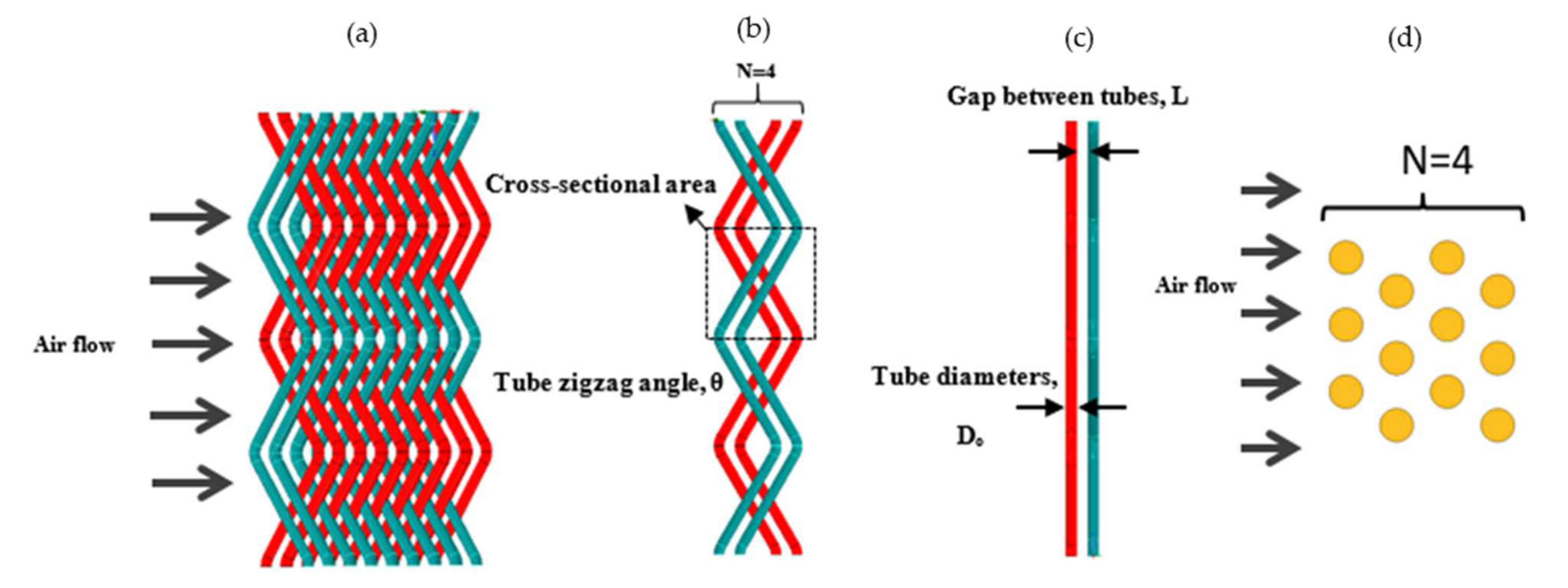
The new finless heat exchanger and parallel tube heat exchanger presented in this study introduce a unique design, as shown in
Figure 1. Unlike conventional heat exchangers that use fins, this design used a very thin diameter (D
o) of tubes arranged in a zigzag pattern at certain intervals, which acted as a tube bundle. The tubes were set side-by-side at different distances, allowing in-depth research into their performances in different configurations. The scope of this study was limited to two rows (N = 2), with air as a working fluid to evaluate the performances of these new heat exchangers across the air flow. To assess the effectiveness of the zigzag shape, several zigzag angles (30°, 45°, and 60°) were examined, while the increase in the tube zigzag angles also increased the tube total heat transfer area significantly. The study included a comparison of the proposed zigzag tube heat exchanger (ZTHX) and a conventional parallel tube heat exchanger (PTHX). To ensure a fair comparison, the configurations of the ZTHX and PTHX had the same parameters, such as the same number of rows (N = 2), the same diameter of tubes, and the same distance between the tubes and the air flow. The primary objective of this study was to explore the potential advantages and disadvantages of the finless ZTHX design and to identify possible improvements to enhance its performance in various applications.
3. CFD Modeling
The computational domain of the ZTHX without fins and the PTHX is shown in
Figure 2, representing a three-dimensional longitudinal cross-section in the direction of the air flow. The numerical simulation used the commercial CFD software ANSYS FLUENT 2021 R2 to examine the design of the ZTHX. The software used the finite volume method to solve a general equation, which included continuity, momentum, and energy equations.
In this simulation, for both the zigzag tube bundle and parallel tube bundle, the tube material was considered as copper. In this particular study, we only checked the cross-flow across the tube bundles (both zigzag tube bundle and parallel tube bundle). To reduce the simulation run time, the grooved surface in the computational domain was considered here as the outer surface at a constant temperature of 313 k.
Although the Reynolds numbers were low, it was expected that turbulence occurred across the boundary layer. This indicated that the Reynolds numbers were not the only factor for the transition of the laminar flow to turbulent flow. The geometry itself could play a vital role in the turbulence, while the laminar flow and turbulent flow regimes both were unknown here. In the current study, from the simulation software two equations for k-ε realizable (RKE) models [
21] were selected, along with the enhanced wall functions enabled in all simulations, to check the flow pattern near the wall. The RKE model provided a higher convergence rate compared to the other models.
All the simulations were conducted in steady-state conditions. A second-order upwind discrepancy scheme was implemented to improve the accuracy of the calculations, minimize numerical dispersion, and ensure accurate prediction of the flow and temperature fields. Air flow was assumed to be incompressible and turbulent. The fluid properties used the ideal gas model for density, and all other properties were assumed to be constant. The convergence criteria were established at 10−3 for continuity, speed, kinetic energy (k), and eddy viscosity (ε) and at 10−6 for energy. These strict criteria ensured that the solutions were numerically stable and accurate. The intensity was taken as 10%.
The governing equations for convective heat transfer were a set of partial differential equations that described the behavior of fluid flow and heat transfer in a turbulent regime. The equations were as follows.
Continuity equation (conservation of mass):
Momentum equation (conservation of momentum):
Energy equation (conservation of energy):
The two equations for the turbulent model (k − ε) are given below.
Turbulent kinetic energy (
k):
Turbulent dissipation rate (
):
The turbulent kinetic energy generation rate
Pk was as follows.
where
= 1,
= 1.3,
= 1.44,
= 1.92, and
= 0.09.
These equations consist of the continuity equation, the momentum equation, and the energy equation. They are derived from the principles of mass, momentum, and energy conservation and are used to model fluid flow and heat transfer problems. ρ is the fluid density, ui and uk are the fluid velocity vector components, p is the pressure, μ is the dynamic viscosity, T is the temperature, k is the thermal conductivity, and cp is the specific isobaric heat.
High-quality meshes are crucial for successful numerical simulations. In this study, the mesh was generated using the FLUENT mesh option. A fine tetrahedral mesh was implemented throughout a 3D domain for both the zigzag tube bundle and the parallel tube bundle with a growth rate of 1.1. Finer mesh elements were utilized near the tube walls to ensure that more detailed and accurate flow structures were captured effectively. This approach was reasonable in cases where the final effect had a minimum effect on overall heat transfer and pressure drop characteristics. Limit conditions were defined as follows: symmetric flow around the wall of the incoming fluid domain had a constant velocity distribution, and the constant pressure at the outlet (0.00 Pa) was the constant pressure.
However, in 3D simulations, the number of elements increases significantly with small changes in the size of the element. This results in a significant increase in computing time. To balance simulation accuracy and CPU time, choosing the optimum mesh size is necessary. In this study, three meshes with different magnitudes of elements in the tube bank zone were generated. These three different mesh levels were called ‘coarse’ mesh, ‘medium’ mesh, and ‘fine’ mesh. The cell numbers for the grid independence test are shown in
Table 1. The deviation in the heat transfer coefficient from the coarse to the fine mesh was 1.17%, and that of the medium mesh to the fine mesh was 0.87%. The deviation in the pressure drop from the coarse to the fine mesh was 4.6%, and that of the medium mesh to the fine mesh was 0.4%.
A total of 48 different geometric patterns covering a wide range of zigzag angles and tube spacings were analyzed. As a sample of mesh quality, with a 45° zigzag angle and a 1 mm spacing between the tubes, the total number of mesh elements was 1,299,505, the skew was 0.21589, and the straightness was 0.86542. These metrics demonstrate the quality of the mesh used in the simulation, ensuring reliable and accurate results when studying the performance of the ZTHX design.
4. Boundary Conditions
The computation domain consisted of a test section having various lengths considering the zigzag tube angle. The upstream flow area was considered 5D, and the downstream flow was considered 20D of the tube diameter to eliminate disturbance. In the inlet, a uniform velocity profile was considered, which was the velocity inlet. Moreover, in the case of the outlet, the pressure outlet was considered, where the pressure was zero (0.0 Pa).
A symmetry boundary condition was considered at the top and bottom of the computational domain. The tube diameter was considered here as 1 mm in all cases. The zigzag angle was considered (30°, 45°, or 60°); the distances between the tubes were 0 mm, 0.5 mm, 1 mm, and 2 mm. The boundary conditions considered were as follows. Air was selected as the working fluid, and four flow rates of water were considered (0.5, 1, 1.5, and 2 m/s).The air inlet temperature was set at 298 k, and the tube wall temperature was set at 313 k, as shown in
Table 2.
5. Data Reduction
In order to compare the zigzag-shaped tube performance, parallel tube data were required. Therefore, to validate the data of the parallel tube in the present work, a correlation was used, which was described by [
20] and is summarized in Equations (9)–(15).
where
j is the Colburn
j factor,
f is the friction factor,
ReDo, C is the Reynolds number,
Do is the outer tube diameter,
Pt is the transverse pitch (mm), and
Pl is the longitudinal tube pitch (mm).
The coefficients of the correlation are listed in the
Table 3.
For the technique of the parallel tube, the CFD data below were considered, which were based on the approach of [
3] and are summarized in Equations (16)–(22) below.
In Equation (19), the tube wall resistance Kw and the refrigerant side resistance Href both are negligible because the tube wall temperature was fixed here. air is the mass flow rate (ks/s), is the heat transfer amount (W), Uair is the heat transfer coefficient (W/m2.K), Afr is the flow cross-sectional area, Ao is the total surface area, umax is the maximum flow velocity, σ is the contraction ratio, ρin is the fluid inlet density, ρout is the fluid outlet density, LMTD is the logarithmic mean temperature difference (K), and A is the total heat transfer area (m2). delta P refers to the pressure difference between the inlet and outlet of the domain.
In the case of zigzag-shaped tube data reduction, the following technique was used, as shown in Equations (16), (17), (23), and (24).
where
cp is the capacity ratio,
Nu is the Nusselt number, and
K is the thermal conductivity (W/m.K).
6. Results and Discussion
6.1. Heat Transfer Area Improvement Percentage
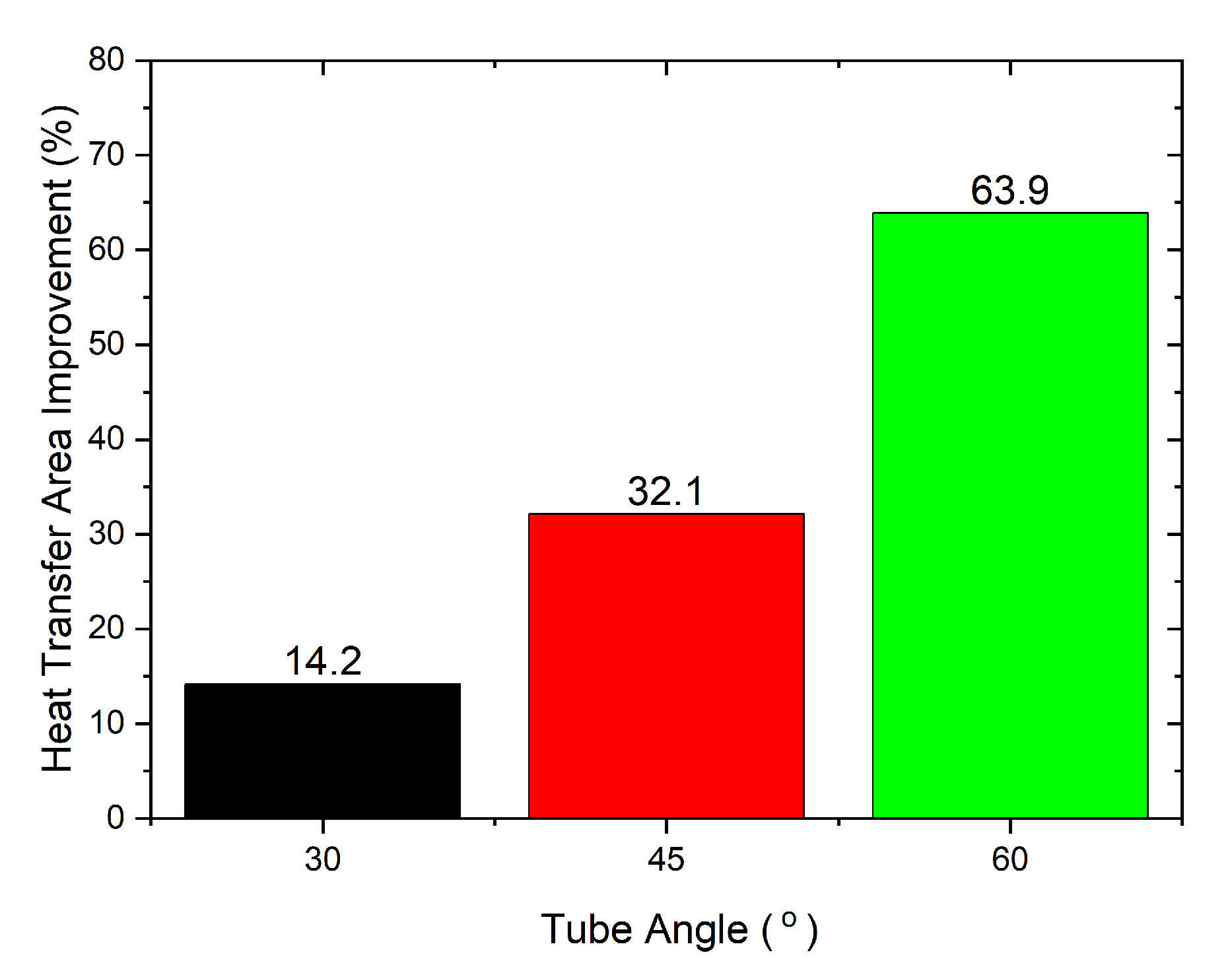
To obtain better heat transfer, increasing the heat transfer area always plays a vital role. In our study, rather than using conventional methods to increase the heat transfer area by using fins, we used a zigzag instead of a parallel tube and created a tube bundle. The introduction of different tube zigzag angles also significantly increased the total heat transfer area. Eventually, this increase in the total heat transfer area also resulted in increased heat transfer of the zigzag tube bundle over the parallel tube bundle.
The increase in heat transfer area was determined by considering a similar frontal area and a similar number of tubes for both the zigzag tube bundles (30, 45, and 60 degrees) and the parallel tube bundle. The percentage of increase in the heat transfer area is shown in
Figure 3. From the figure, the heat transfer area increased by 14.2%, 32.1%, and 63.9% for tube zigzag angles of 30°, 45°, and 60°, respectively, over the parallel tube banks.
6.2. Flow Characteristics
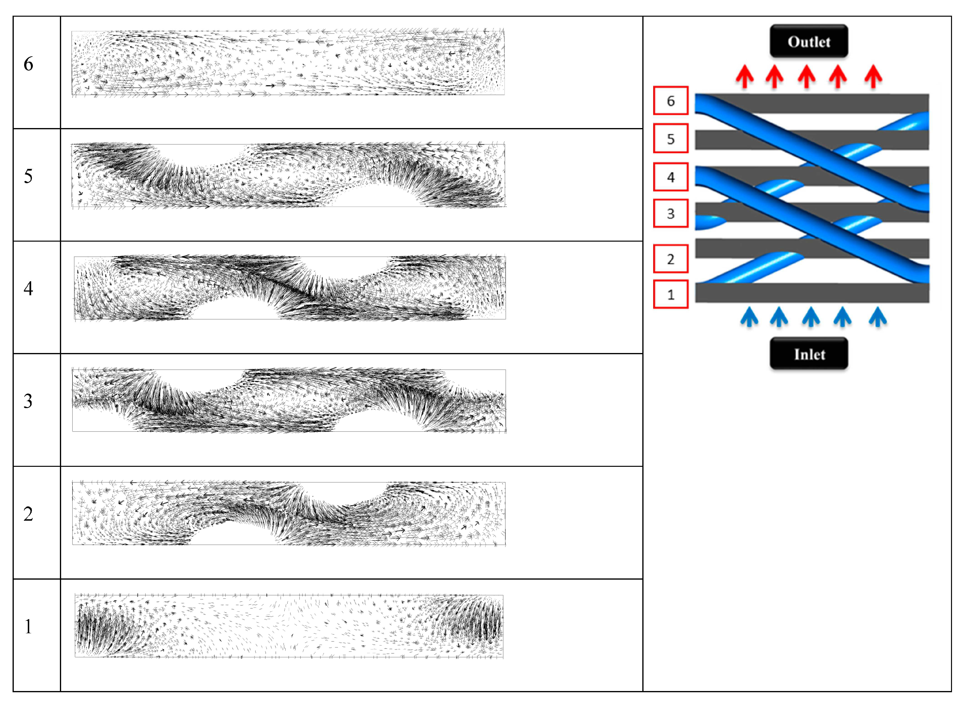
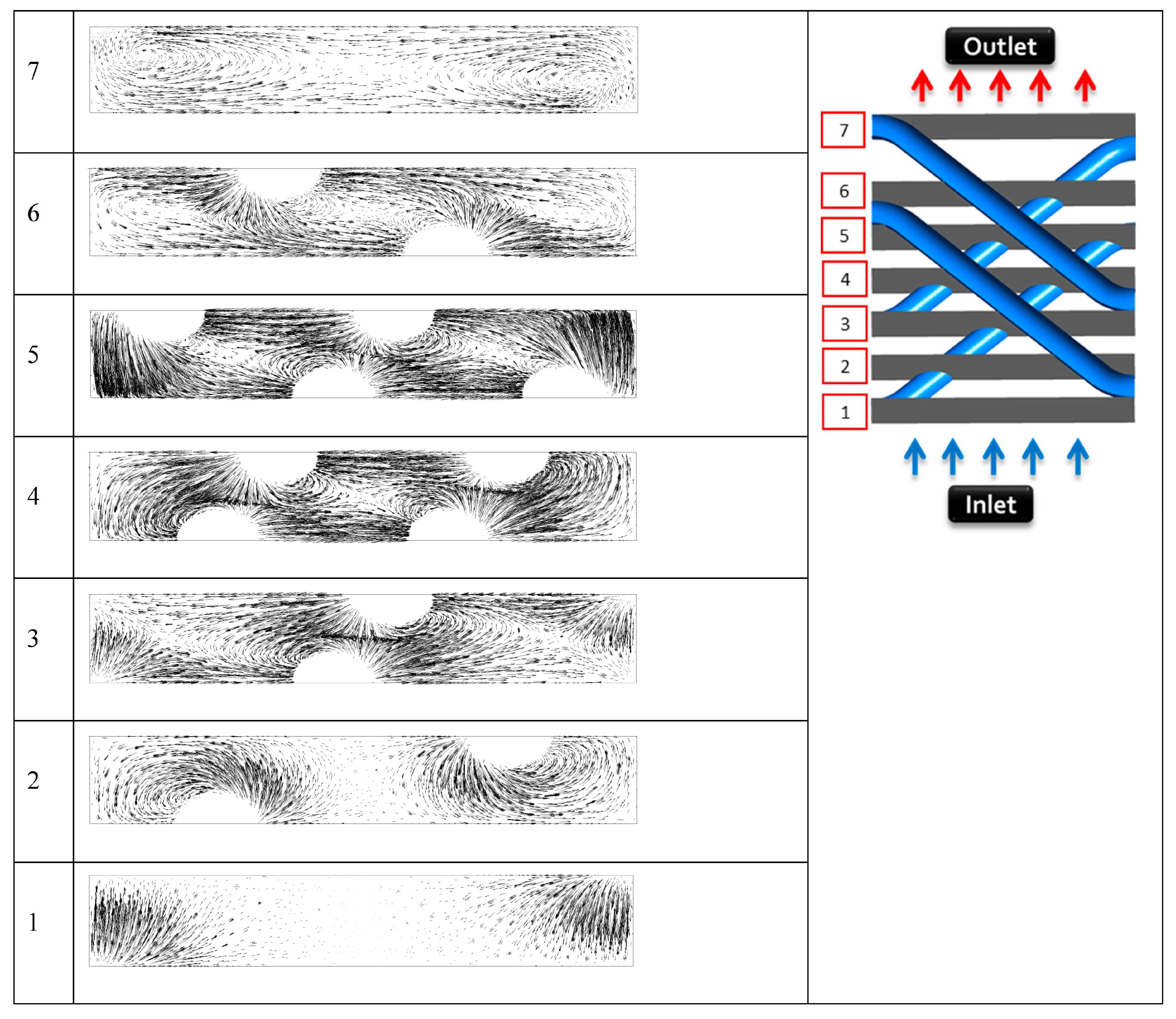
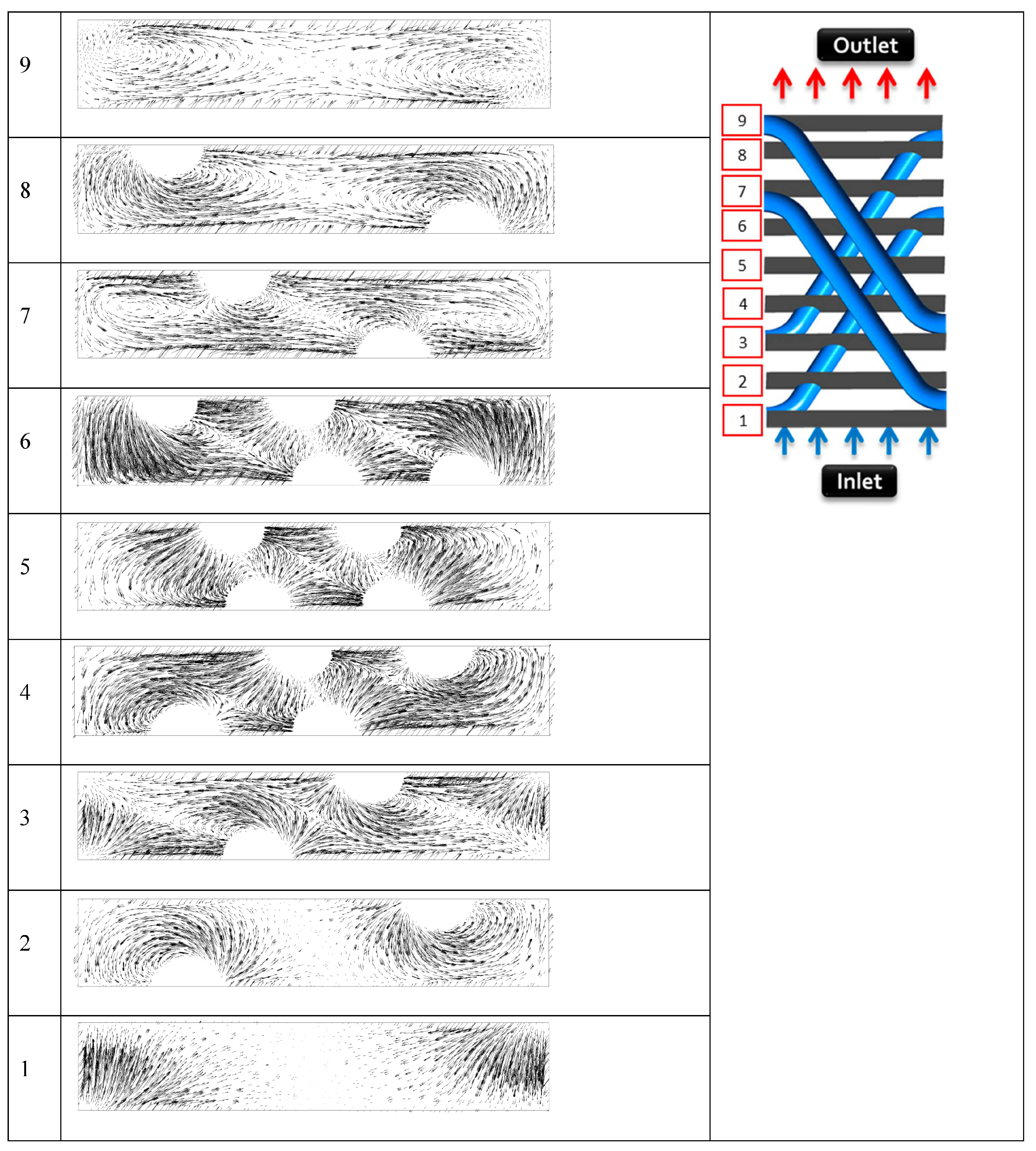
Figure 4,
Figure 5 and
Figure 6 show a comparison of the tangent velocity vector on the cross-sectional surfaces of the computational domains of three tube angles of 30°, 45°, and 60°. The cross-sectional tangent velocity vector is shown from the start of the zigzag tube on the upstream side to the end of the zigzag tube on the downstream side of the computational domain. This investigation was conducted to observe how the air flow behaved while it passed through the computational domain of the zigzag tube. After the air flowed over the three different tube zigzag angles, because of the different tube angles (30°, 45°, and 60°), it created an anticlockwise vortex around the zigzag tube. The shape of the vortex became stronger and larger with the increase in the zigzag angle of the tube.
These vortices broke the thermal boundaries and improved the exchange of hot and cold air. Eventually, these vortices, which were created by using different zigzag tube angles (30°, 45°, and 60°), helped to increase the heat transfer performance. Another important thing to be observed is that, along the air flow direction, the intensity of the vortices increased in the middle of the domain. It occurred for the other two tubes used in places right under the upper two tubes, which created a crossed shape in the middle of the domain. These crossed tubes on the upper side and lower side individually created vortices as soon as air flowed.
Figure 4,
Figure 5 and
Figure 6 show a distance between the upper tubes and the lower tubes of 0.5 mm. The effect and behavior of the vortices was different. The following analysis in this paper demonstrates the behaviors of the different angles of zigzag tubes (30°, 45°, and 60°) and distances between the tubes (0 mm, 0.5 mm, 1 mm, and 2.0 mm).
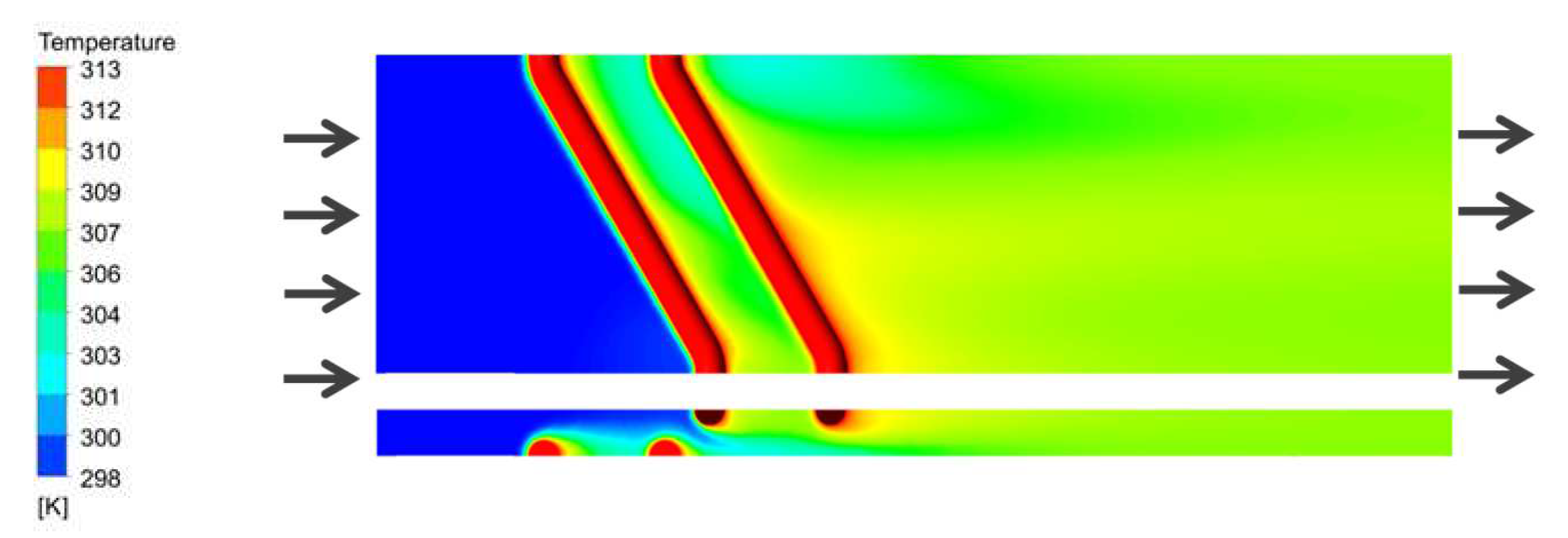
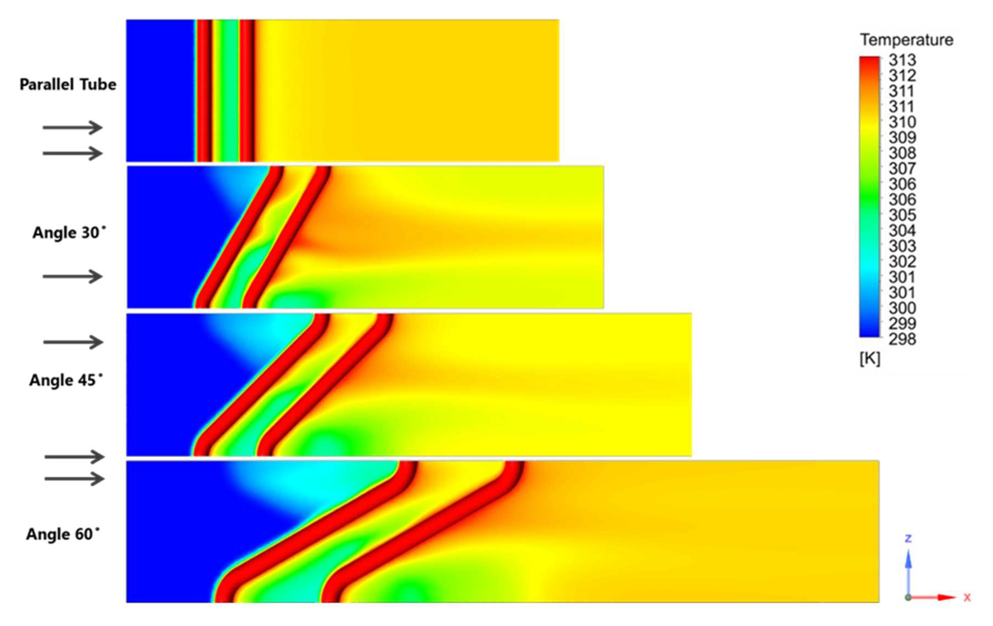
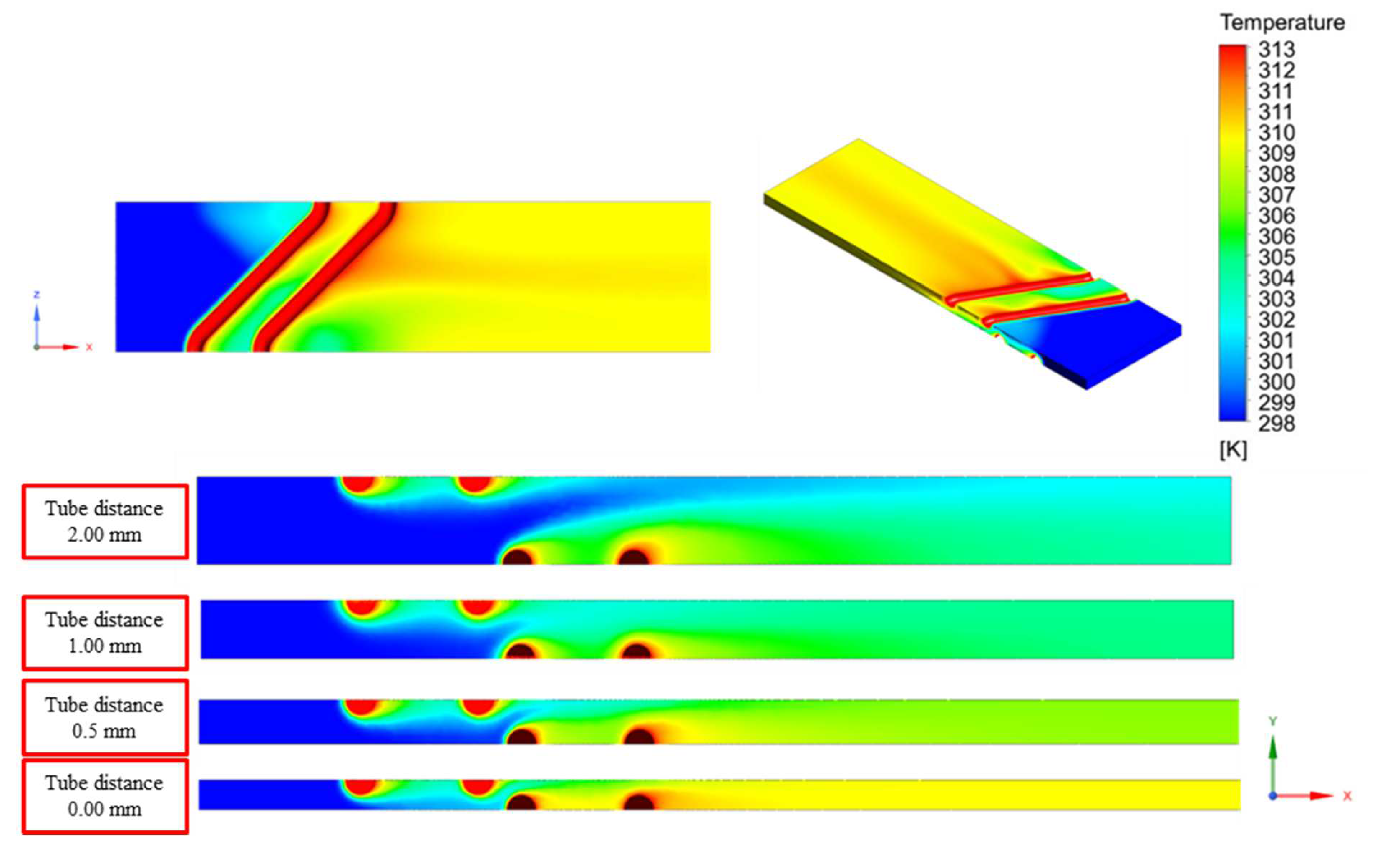
Figure 7 and
Figure 8 show the top view and side view, respectively, of the temperature contours of the three different zigzag tube angles (30°, 45°, and 60°) of the computational domain. It is clearly shown that, in the middle of the zigzag tube domain, the exchange between the hot and cold air increased sharply.
Moreover, in
Figure 7 and
Figure 8 the computational domain was increased compared to the parallel tube computational domain. Therefore, the generated vortices had a longer time to pass through the zigzag tubes in the downstream direction. Eventually, the heat transfer rate increased.
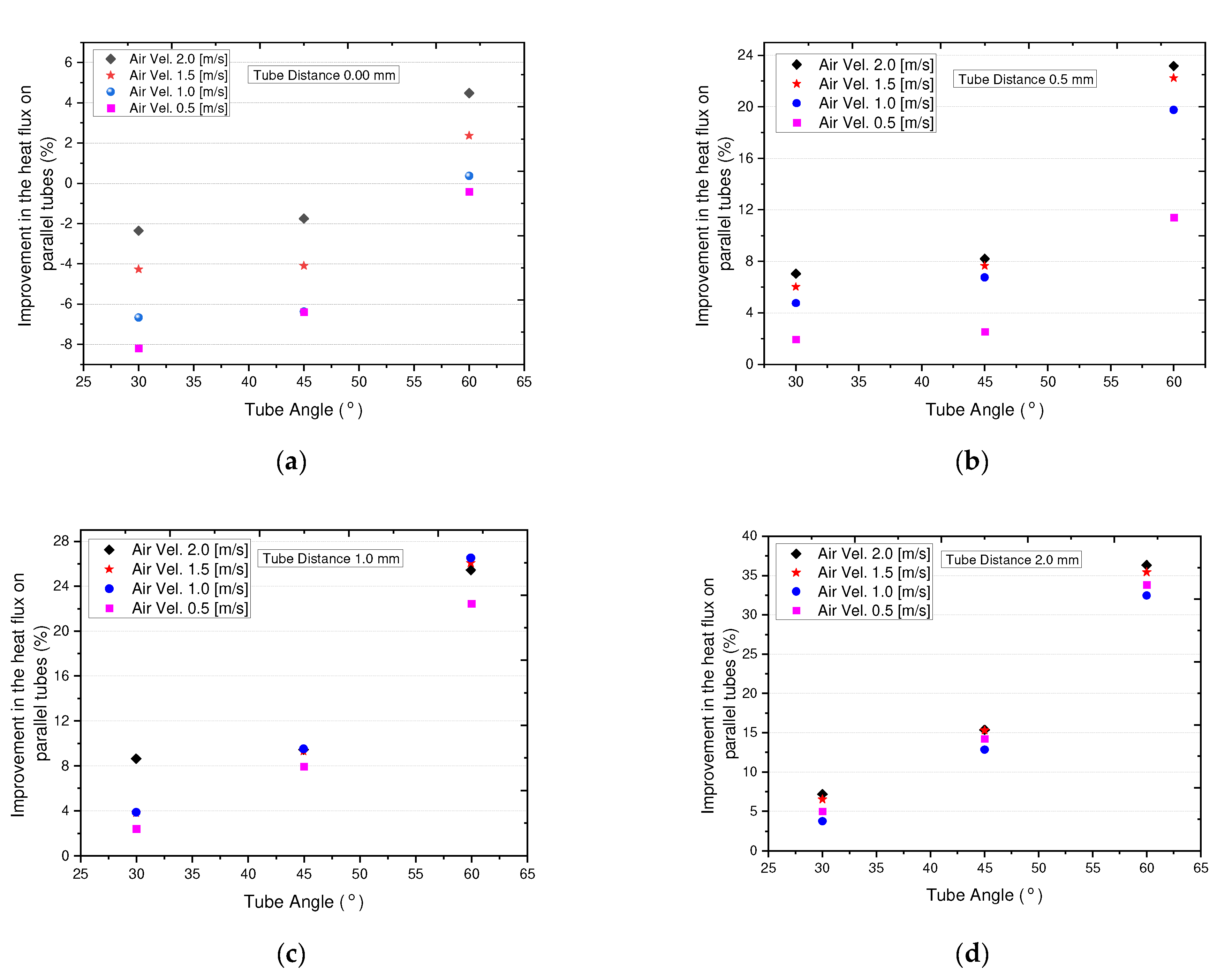
6.3. Heat Flux Percentage Improvement
The percentage of improvement in the heat flux of the ZTHX compared to the PTHX is shown in
Figure 9. Different colors of dots represent different air velocities. Here, we discuss the effects of air velocity, distance between tubes, and zigzag angles on heat flux.
As the air velocity increased, the air-side heat flux percentage increased nonlinearly for all cases, while the increasing rate fluctuated from case to case. Heat transfer showed an incremental trend, except when the distance between the angles of the tubes was 0.0 mm and the zigzag tube was 45° or less. Only in this case did the PTHX show a better performance. Additionally, when the distance between the zigzag-shaped tubes increased, the air-side heat flux increased. Among the angles in the four cases, the zigzag tube had a more considerable influence on the improvement in the heat transfer performance. For example, when the zigzag tube angle was higher at 60°, the improvement in the heat flux was more increased. Additionally, with an increase in the distance between the zigzag tubes, the rate of improvement of the heat flux increased. The influence of the increase in air velocity is also shown by similar increasing trends among the four graphs; as air velocity increased, the improvement in heat flux increased. They indicate that a more significant distance between tubes with larger zigzag angles was preferred for a higher performance of heat flux improvement for the ZTHX.
Among these three factors, the zigzag angle had a significant influence because, among the four data sets, a larger tube zigzag angle showed a better performance every time. The air velocity also had a significant impact when the distance between the tubes was greater. Only in two cases where the distance between the tubes was 0.0 mm and the zigzag tube angle was 45 or less did the PTHX exceed the performance of the ZTHX for heat flux percentage.
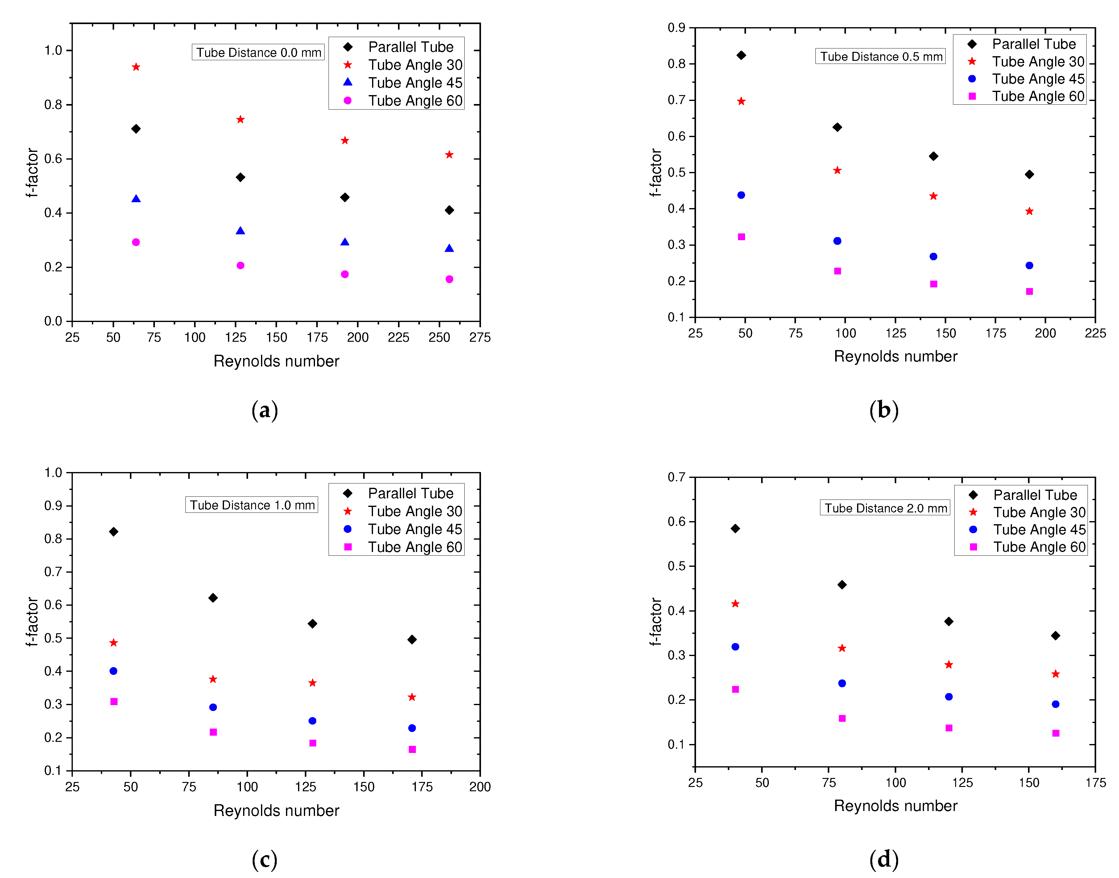
6.4. Calculation of Friction Factor
Figure 10 shows the variation in the f factor with frontal air velocity in the range of 0.5–2.0 m/s, and it is represented in terms of the Reynolds number. For the conversion,
Do was used as the characteristic length scale. The friction factor was calculated from the pressure drop equation proposed by Kays and London 1984 [
22]. In
Figure 10, different colors of dots show other zigzag tubes and bare tubes. Here, we discuss the influences of the Reynolds number, the distance between tubes, and the tube zigzag angles over the air friction factor.
The distance between the zigzag tubes and the parallel tubes played a significant role in the f factor. It is clearly shown that, under all the circumstances, the parallel tube f factor surpassed the zigzag tube f factor. The f factor showed a lower value when the distance between the tubes increased. The Reynolds number also played an important role on the f factor. Among the four data sets, it can be observed that the f factor showed a decreasing trend with increasing Reynolds number. Interestingly, when the angle of the zigzag tube was higher, the f factor decreased in all the cases.
6.5. hA Value Calculation
To find improvements in the heat transfer of the geometry itself, a comparison of hA was required, which is the product of the heat transfer coefficient and the heat transfer area [
23]. The hA values are shown in
Figure 11 with respect to different tube angles. On the graph, it is evident that the hA values of the zigzag-shaped tube heat exchangers were higher than those of the corresponding parallel tube heat exchangers. The hA value increased as the velocity of the air increased and the zigzag angle increased. The increasing zigzag angles of the zigzag tube bundles resulted in a larger total heat transfer area, which explains the upward trend of the hA values compared to the parallel tube bundle. In the current calculation of hA, A is the heat transfer area of the calculation area, and h is the heat transfer coefficient. In addition, the hA values showed a higher value when the distance between the tubes was smaller.
6.6. Parallel Tube Data Validation
To validate the current study, the parallel tube simulation data were first validated with an existing correlation, and then the parallel tube simulation data were again used for comparison with the zigzag-shaped tube simulation. In the case of parallel tube banks, the use of smaller tube diameters is rare. Recently, Bacellar et al. [
20] performed some work on the case of a tube of a smaller diameter.
Table 3 shows the correlation coefficients. Therefore, in this study, the parallel tube heat exchanger was validated with the proposed correlations by Bacellar et al., and then the parallel tube data were compared with the zigzag-shaped tube data. The results gathered are shown in
Table 4. At higher air velocities, the effect of temperature on fluid properties became more pronounced, as observed with the air velocity of 4.0 m/s. The correlation predicted the
j factor more accurately for relatively lower air velocities, such as 2.0 and 3.0 m/s. Ultimately, differences in temperature between the correlations and our study resulted in larger deviations in the j factor. According to the results collected, we can say that the numerical simulation was reliable.
Another correlation was proposed by Žukauskas [
16] for tube banks both in line and staggered in 1972 and is shown in Equation (25).
For staggered tube rows N = 2, 10 ≤ ReDmax ≥ 500, F = 0.76, C = 1.04, n = 0.4, and m = 0.36.
The parallel tube simulation data were also validated with the Žukauskas correlations, but significant discrepancies were obtained for air velocities of 2 m/s and 1.5 m/s of 55% and 69%, respectively. These discrepancies can be attributed to considerable differences in geometric parameters between this study and those underlying Žukauskas’s correlations. In heat transfer calculations for a tube bank, the tube diameter can significantly impact the heat transfer coefficients and, hence, the Nusselt number. The diameter of the tubes in this study was significantly smaller (1 mm) than the tube diameters for which the correlations were originally developed. Most experimental works have relied on validations involving larger-diameter tubes of 7 mm or more. However, the correlations of Bacellar et al. [
20] were a great match with our current study configuration.
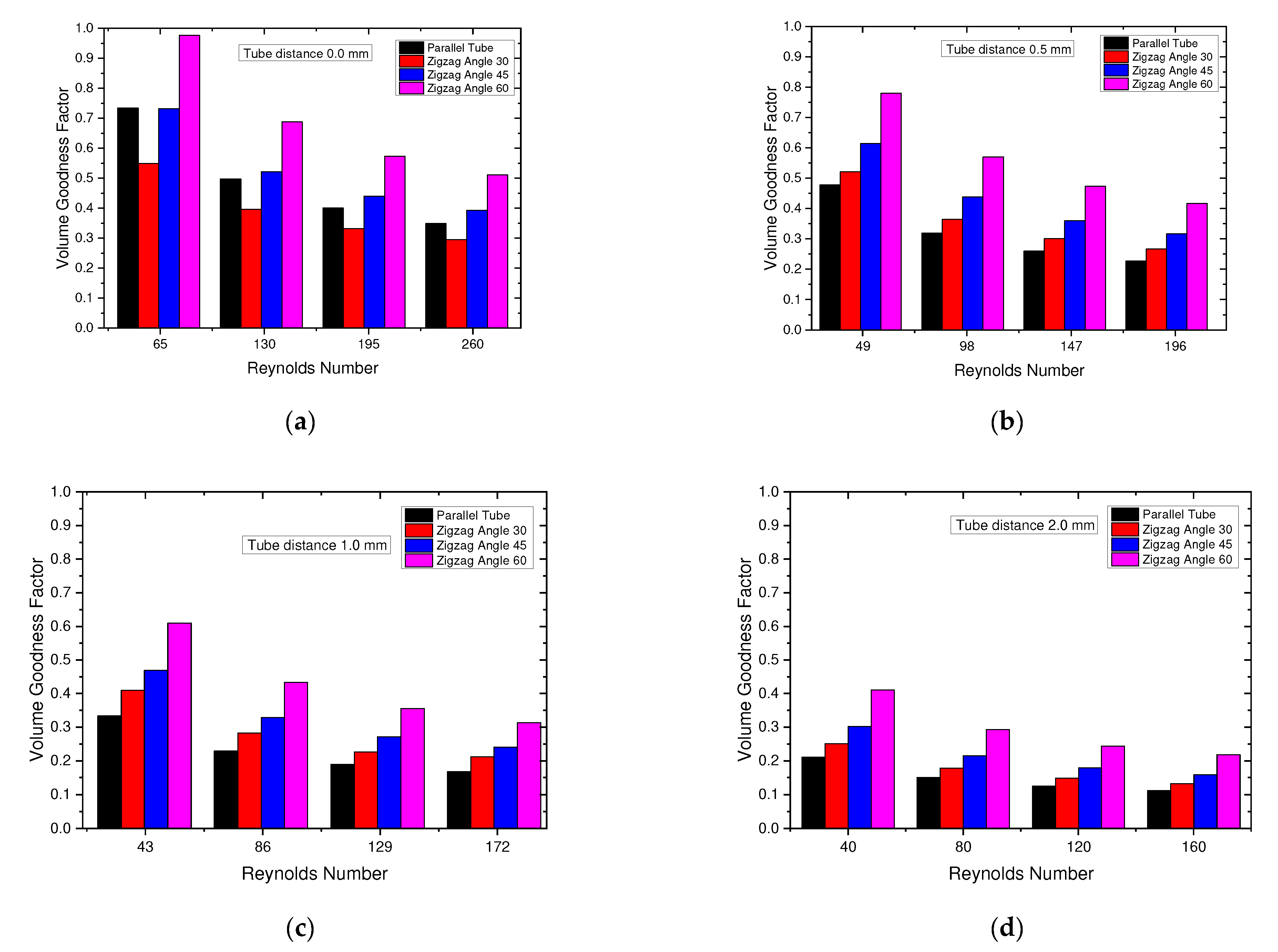
6.7. Volume Goodness Factor
To evaluate the efficiency of increasing the heat transfer improvement, the pressure reduction and heat transfer coefficients should be considered simultaneously. The performance of the newly designed heat exchanger needed to be checked. Using the performance evaluation criterion (PEC), the volume goodness factor
has been widely adopted to evaluate performance [
24,
25,
26,
27,
28]. This relationship is known as the Reynolds–Colburn analogy. Here,
j is the Colburn
j factor, and
f is the friction factor.
A higher volume goodness factor needs a small volume to show the same performance in terms of heat transfer rate. In
Figure 12, we can observe the performance of the volume goodness factor. Here, different colors denote different types of tubes. From the figures, it is clearly shown that the volume goodness factor decreased with increasing Reynolds number. However, when it comes to the volume goodness factor, there is no general consensus on its direct relationship to the Reynolds number. The volume goodness factor is a performance evaluation criterion that is used to assess the efficiency of heat transfer improvement methods. It represents the ratio of heat transfer enhancement to the volume of the heat exchanger. Moreover, in the case of the same Reynolds number, the volume goodness factor showed a better value in the case of the higher-zigzag-angled tube. Therefore, with an increase in the zigzag tube angle, the volume showed a better value.
The influence of the distance between the tubes was also inevitable. On the basis of the figure, it is shown that, when the distance between the tubes was lower, the volume goodness factor value showed a better value. With increasing distances between the tubes, the volume goodness factor gradually showed lower values.
Therefore, it was finally considered that a lower Reynolds number, a higher tube zigzag angle, and a lesser distance between the tubes was desired to obtain a better volume goodness factor value.
7. Conclusions
In this paper, considering the drainage problem of conventional fin-and-tube heat exchangers, we proposed a finless zigzag-shaped heat exchanger to eliminate the drainage problem. Using a zigzag tube bundle with varying angles of 30°, 45°, and 60°, different distances between the tubes (0 mm, 0.5 mm, 1 mm, and 2 mm) and different air flow rates (0.5, 1, 1.5, and 2 m/s) were observed. Using numerical simulations, the performance of the zigzag tube bundle was evaluated and compared with that of a parallel tube bundle. The results are presented below.
Heat transfer enhancement was obtained by increasing the total heat transfer area over that of the parallel tube bundle by incorporating different tube zigzag angles. The heat transfer area increased mainly for the tube zigzag angle of 60° by 63.9%.
Heat flux increased to 37% over the parallel tube bundle for the tube zigzag angle of 60° and at an air velocity of 2 m/s.
The friction factor of the zigzag tube bundle was minimal compared to that of the parallel tube bundle when the air velocity was 2 m/s and the distance between the tubes was 2.0 mm.
To achieve a better performance of the zigzag tube bundle compared to the parallel tube bundle, in this study a zigzag angle of the tube of 60°, a distance between the tubes of 2.0 mm, and maximum air velocity were recommended.
The findings of this paper can be a reference for further study on more tube rows of a zigzag tube bundle, both numerically and experimentally. This paper can be a useful material for designing new tube bundle structures.


