
How Does the Micro-Groove Profile Influence the Mechanics of Taper Junction in Hip Implants? A Finite Element Study

Abstract
:1. Introduction
2. FE Model
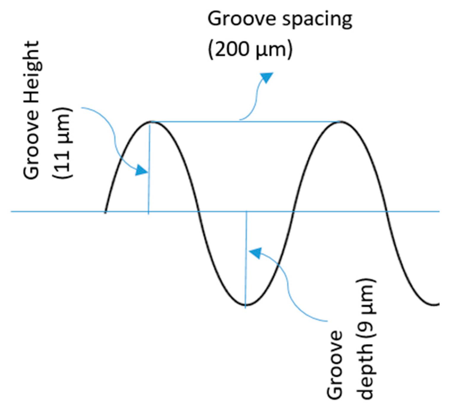
2.1. Model Design
2.2. Material Model
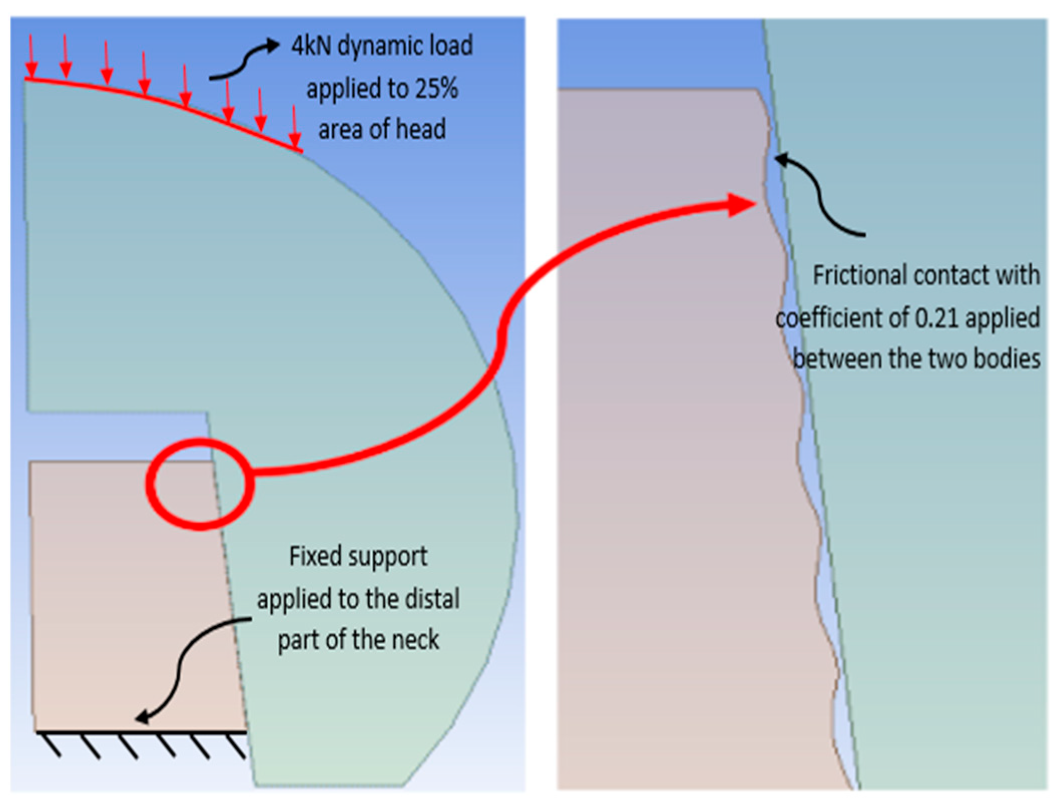
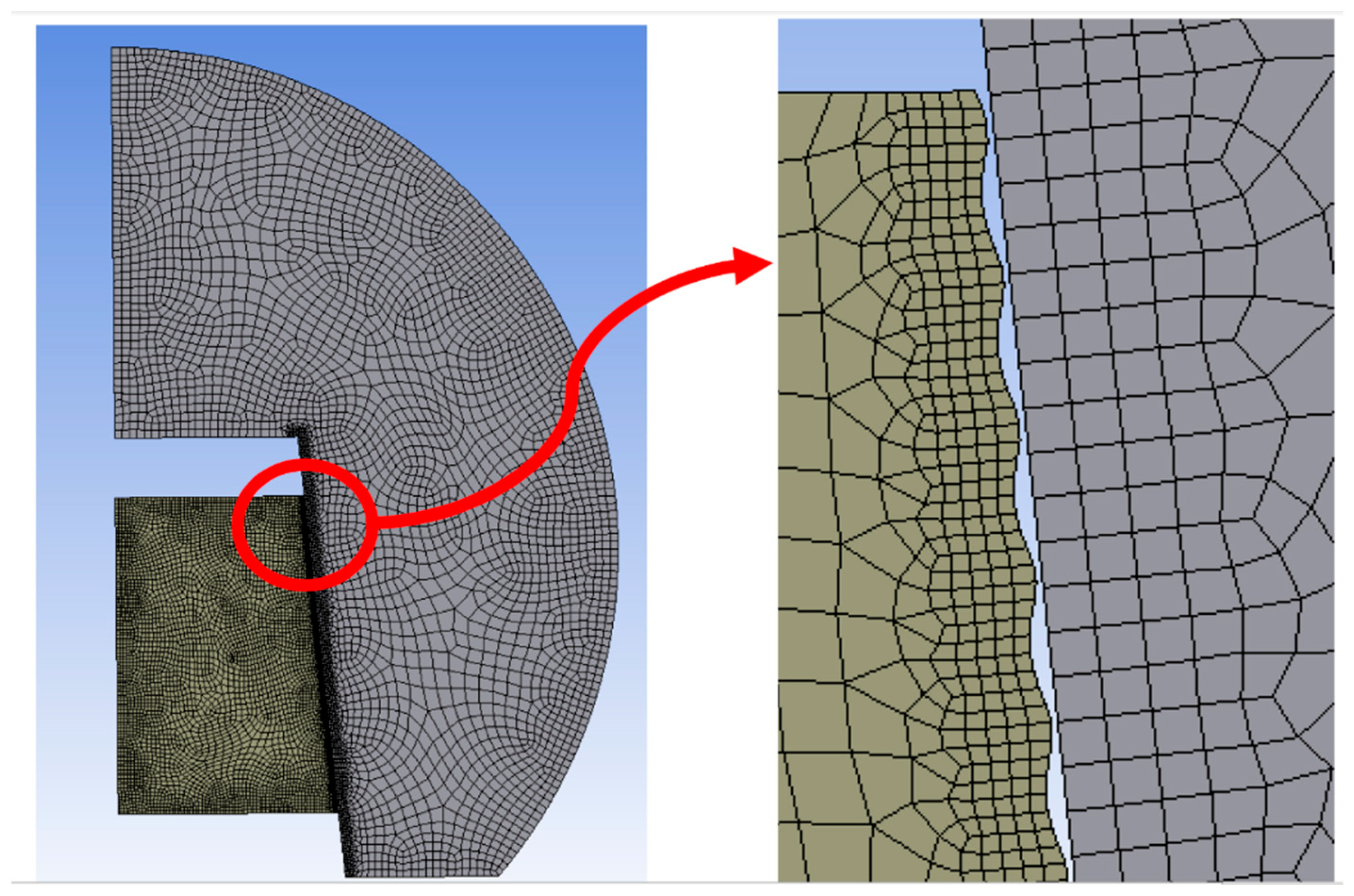
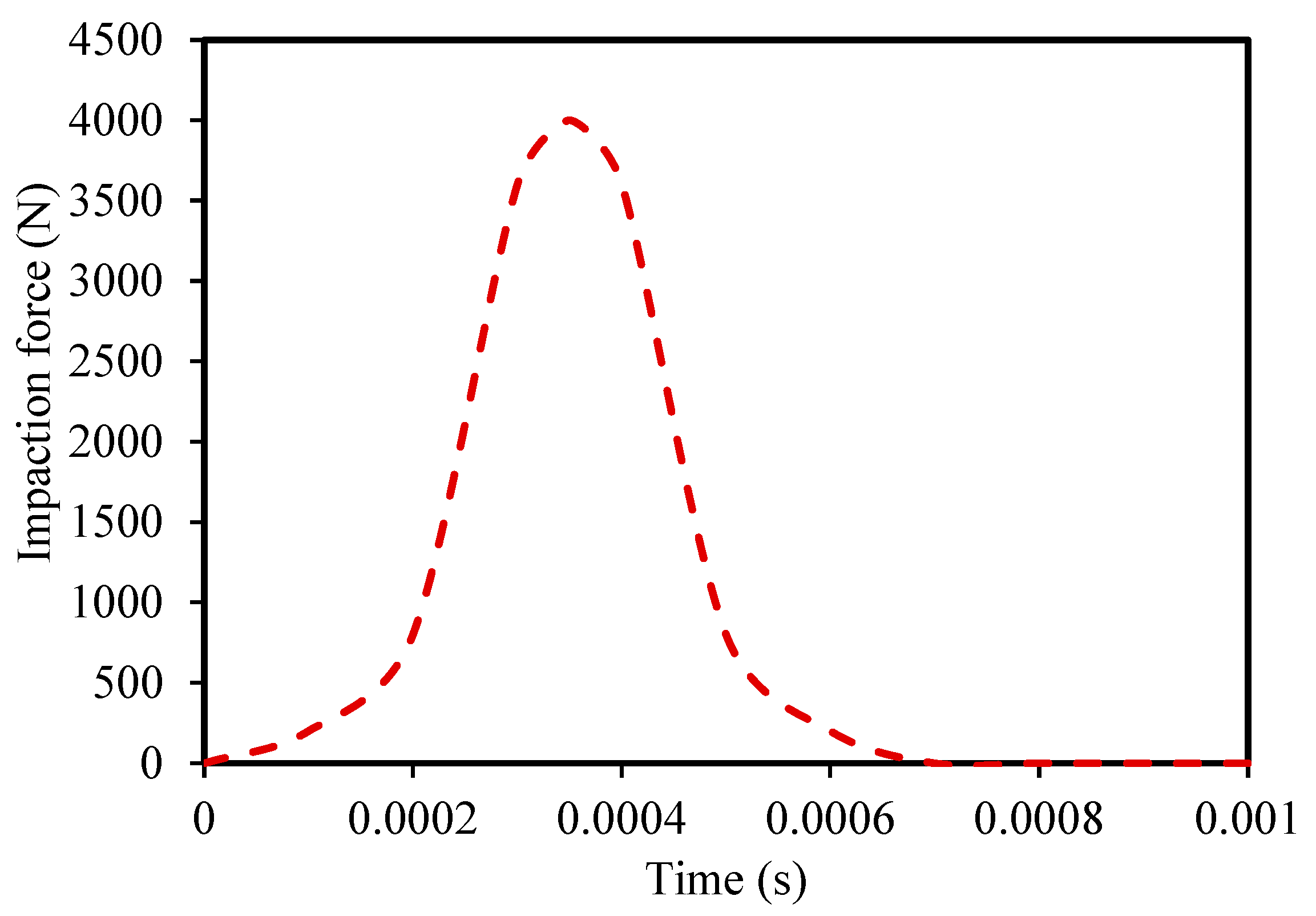
2.3. Meshing and Boundary Conditions
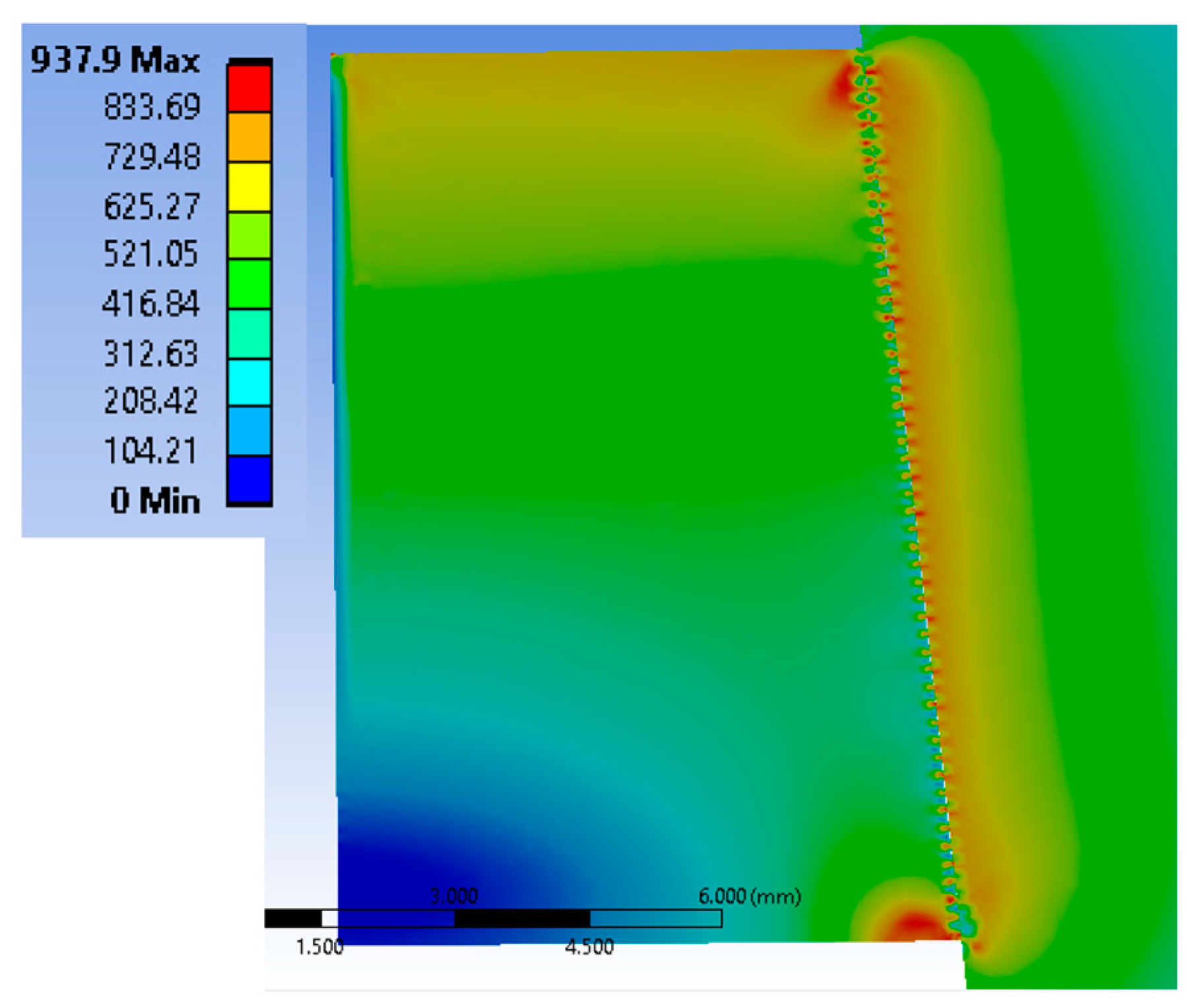
3. Results
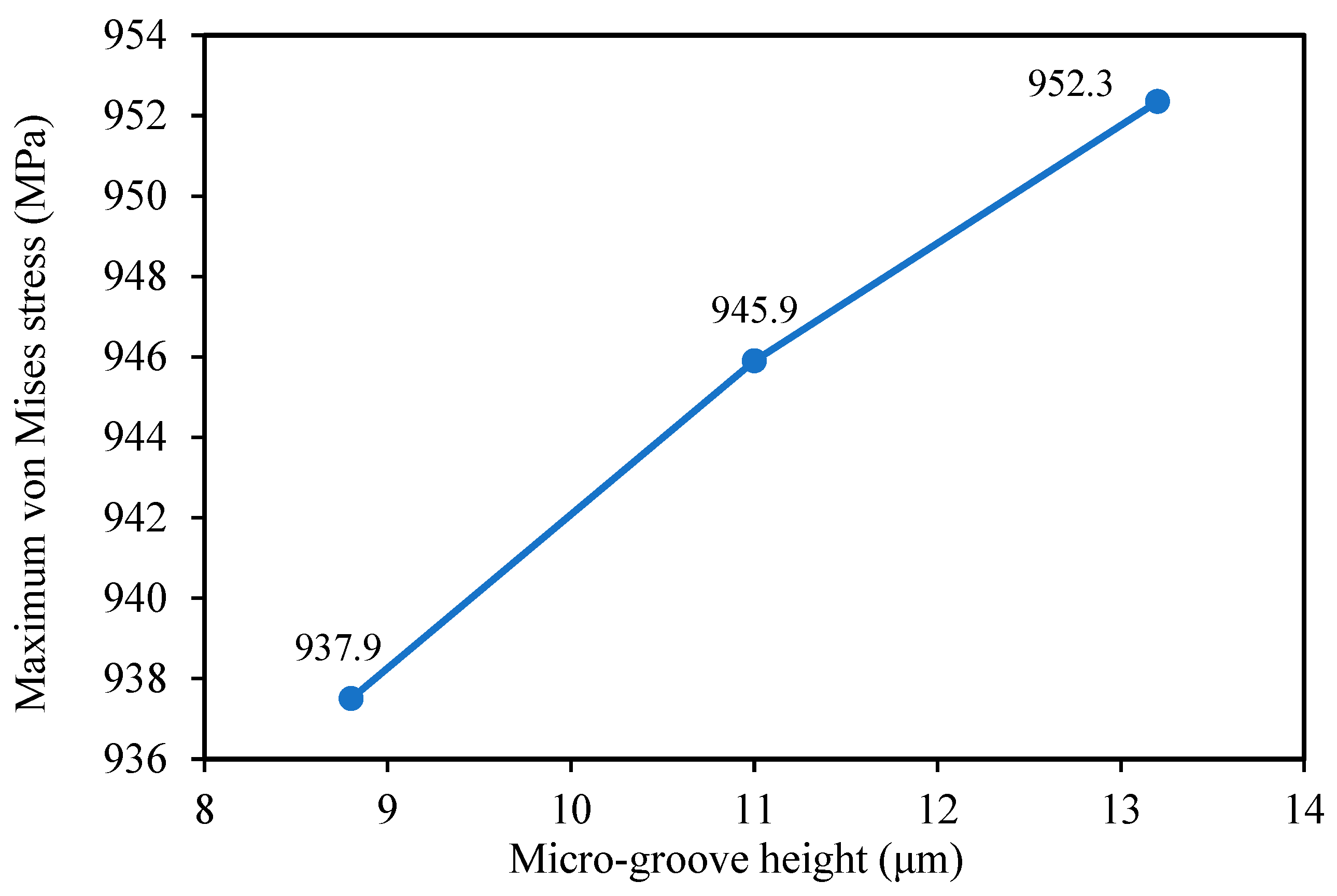
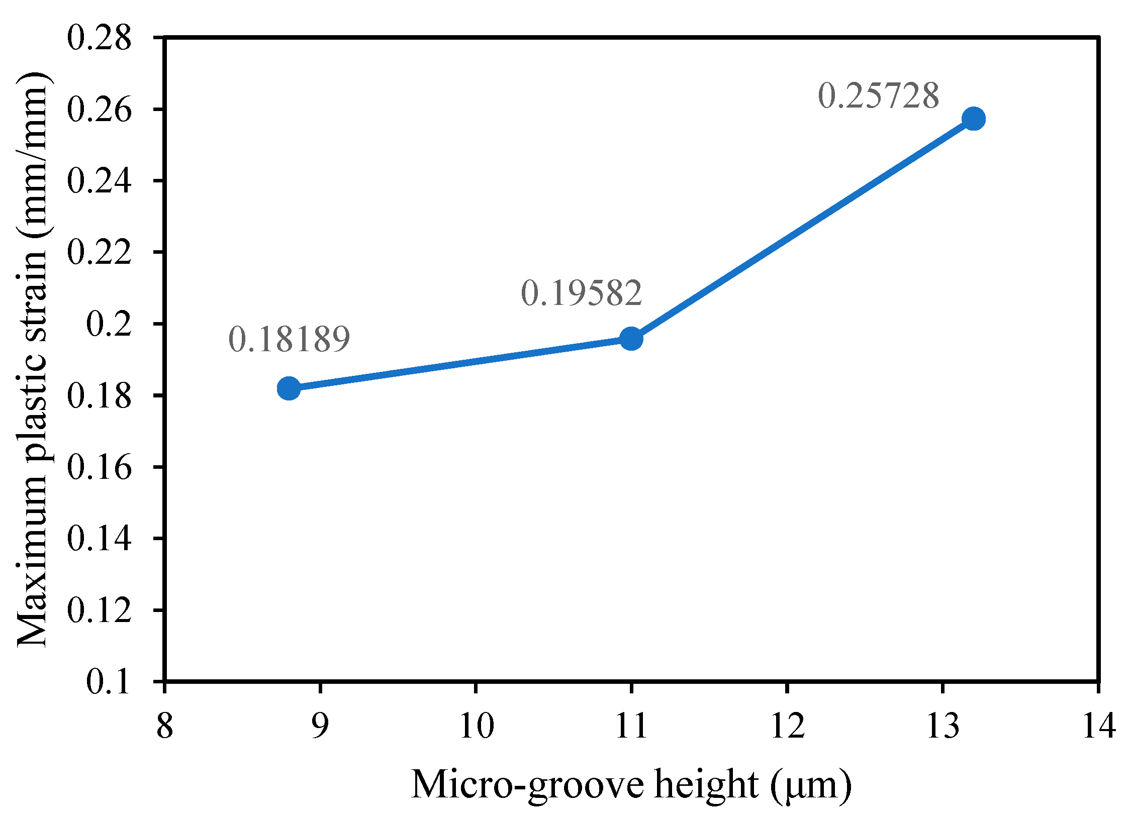
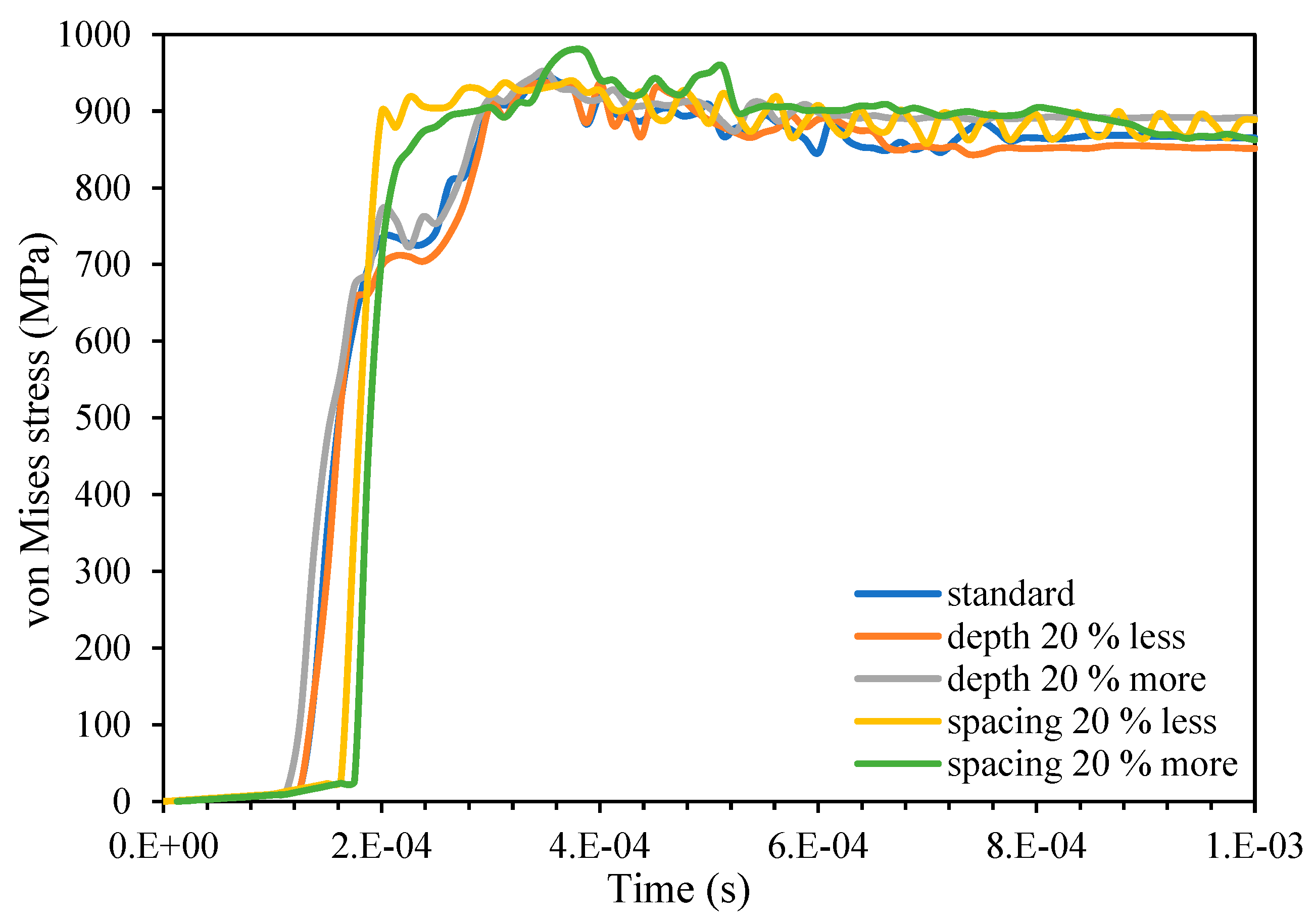
3.1. The Influence of Micro-Groove Height
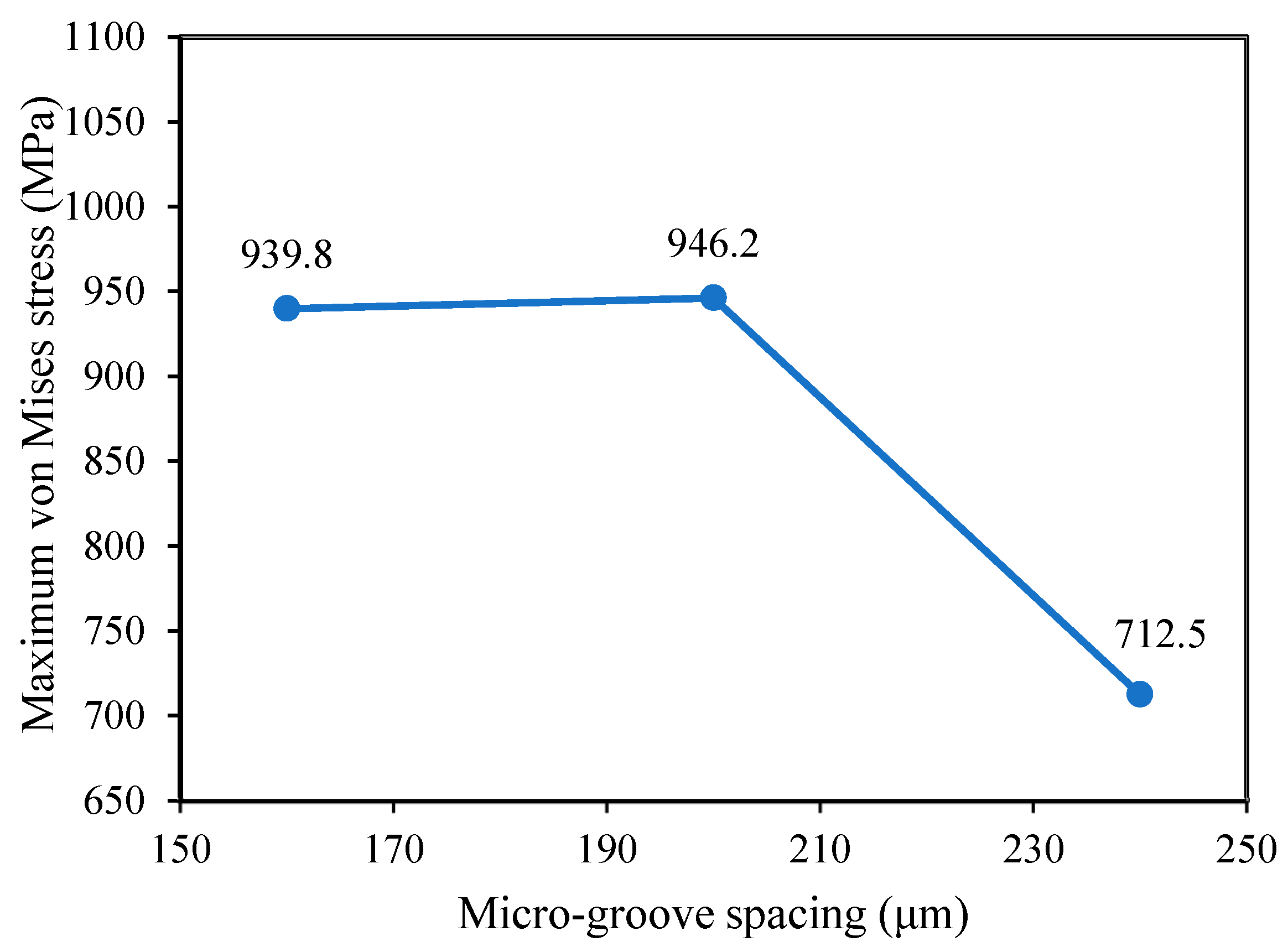
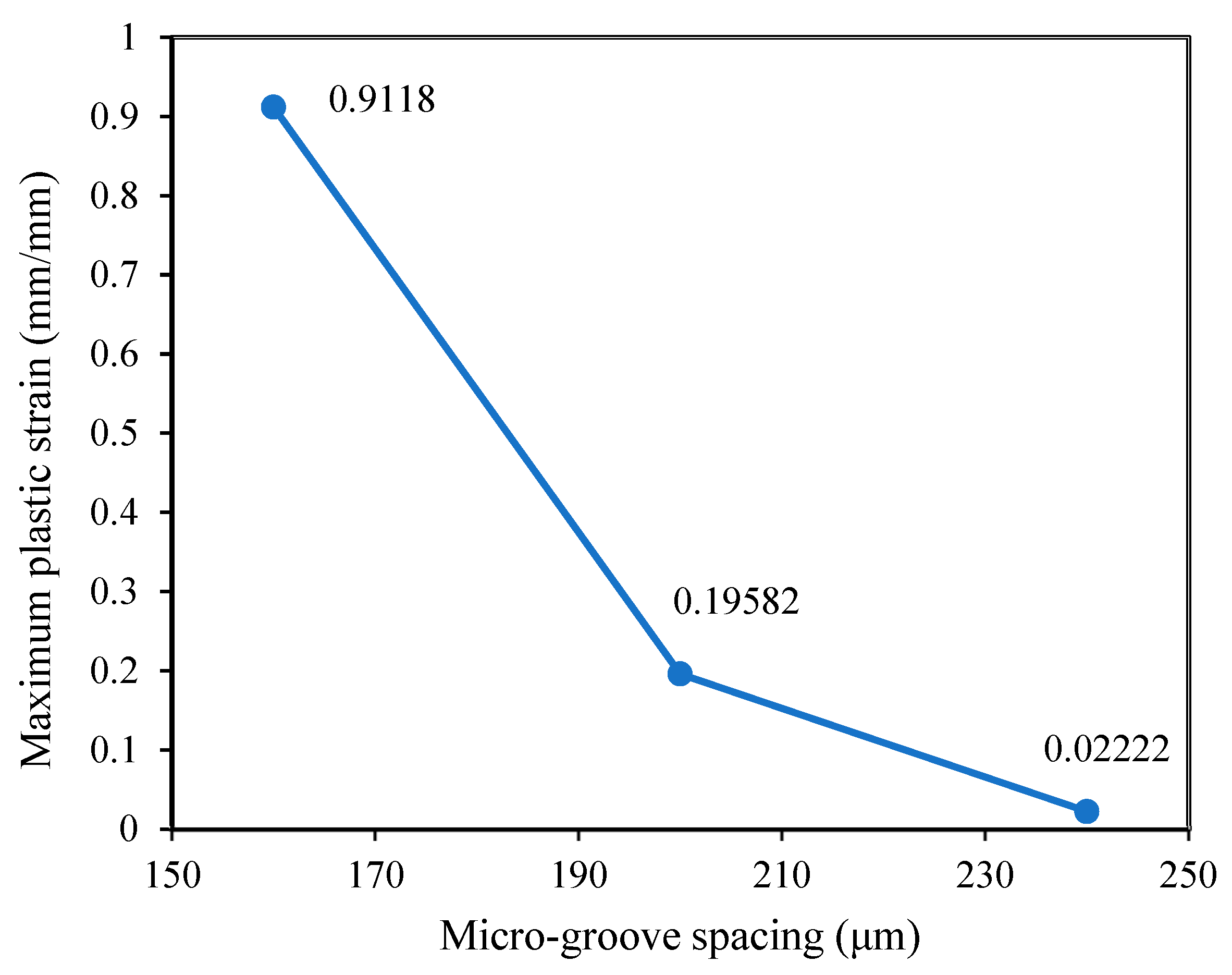
3.2. The Influence of Micro-Groove Spacing
4. Discussion
5. Conclusions
Author Contributions
Funding
Institutional Review Board Statement
Informed Consent Statement
Data Availability Statement
Conflicts of Interest
References
- Hussenbocus, S.; Kosuge, D.; Solomon, L.; Howie, D.; Oskouei, R.H. Head-neck taper corrosion in hip arthroplasty. BioMed Res. Int. 2015, 2015, 758123. [Google Scholar] [CrossRef] [PubMed]
- Oskouei, R.H.; Barati, M.R.; Farhoudi, H.; Taylor, M.; Solomon, L.B. A new finding on the in-vivo crevice corrosion damage in a CoCrMo hip implant. Mater. Sci. Eng. C 2017, 79, 390–398. [Google Scholar] [CrossRef] [PubMed]
- Feyzi, M.; Fallahnezhad, K.; Taylor, M.; Hashemi, R. The mechanics of head-neck taper junctions: What do we know from finite element analysis? J. Mech. Behav. Biomed. Mater. 2021, 116, 104338. [Google Scholar] [CrossRef] [PubMed]
- Feyzi, M.; Fallahnezhad, K.; Taylor, M.; Hashemi, R. A review on the finite element simulation of fretting wear and corrosion in the taper junction of hip replacement implants. Comput. Biol. Med. 2021, 130, 104196. [Google Scholar] [CrossRef] [PubMed]
- Hernigou, P.; Queinnec, S.; Flouzat Lachaniette, C.H. One hundred and fifty years of history of the Morse taper: From Stephen A. Morse in 1864 to complications related to modularity in hip arthroplasty. Int. Orthop. 2013, 37, 2081–2088. [Google Scholar] [CrossRef] [PubMed]
- Wight, C.M.; Lanting, B.; Schemitsch, E.H. Evidence based recommendations for reducing head-neck taper connection fretting corrosion in hip replacement prostheses. Hip Int. 2017, 27, 523–531. [Google Scholar] [CrossRef]
- Ashkanfar, A.; Langton, D.J.; Joyce, T.J. Does a micro-grooved trunnion stem surface finish improve fixation and reduce fretting wear at the taper junction of total hip replacements? A finite element evaluation. J. Biomech. 2017, 63, 47–54. [Google Scholar] [CrossRef]
- Raji, H.Y.; Shelton, J.C. Prediction of taper performance using quasi static FE models: The influence of loading, taper clearance and trunnion length. J. Biomed. Mater. Res. Part B Appl. Biomater. 2019, 107, 138–148. [Google Scholar] [CrossRef]
- Bechstedt, M.; Gustafson, J.A.; Mell, S.P.; Gührs, J.; Morlock, M.M.; Levine, B.R.; Lundberg, H.J. Contact conditions for total hip head-neck modular taper junctions with microgrooved stem tapers. J. Biomech. 2020, 103, 109689. [Google Scholar] [CrossRef]
- Gustafson, J.A.; Pourzal, R.; Levine, B.R.; Jacobs, J.J.; Lundberg, H.J. Modelling changes in modular taper micromechanics due to surgeon assembly technique in total hip arthroplasty. Bone Jt. J. 2020, 102, 33–40. [Google Scholar] [CrossRef]
- Feyzi, M.; Fallahnezhad, K.; Taylor, M.; Hashemi, R. An Overview of the Stability and Fretting Corrosion of Microgrooved Necks in the Taper Junction of Hip Implants. Materials 2022, 15, 8396. [Google Scholar] [CrossRef] [PubMed]
- Fallahnezhad, K.; Farhoudi, H.; Oskouei, R.H.; Taylor, M. Influence of geometry and materials on the axial and torsional strength of the head–neck taper junction in modular hip replacements: A finite element study. J. Mech. Behav. Biomed. Mater. 2016, 60, 118–126. [Google Scholar] [CrossRef] [PubMed]
- Landolt, D.; Mischler, S.; Stemp, M. Electrochemical methods in tribocorrosion: A critical appraisal. Electrochim. Acta 2001, 46, 3913–3929. [Google Scholar] [CrossRef]
- Kashyap, V.; Ramkumar, P. Feasibility study of micro-groove cross hatched surface texturing on Ti6Al4V for improved biotribological performance in metal-on-polymer hip implant. Tribol.-Mater. Surf. Interfaces 2019, 13, 150–160. [Google Scholar] [CrossRef]
- Godoy, M.; Gustafson, J.A.; Hertzler, J.S.; Bischoff, J.E.; Pourzal, R.; Lundberg, H.J. Model validation for estimating taper microgroove deformation during total hip arthroplasty head-neck assembly. J. Biomech. 2022, 140, 111172. [Google Scholar] [CrossRef]
- Arnholt, C.M.; Underwood, R.; MacDonald, D.; Higgs, G.; Chen, A.; Klein, G.; Hamlin, B.; Lee, G.; Mont, M.; Cates, H. Micro-Grooved Surface Topography Does Not Influence Fretting Corrosion of Tapers in THA: Classification and Retrieval Analysis. Master’s Thesis, Drexel University Philadelphia, Philadelphia, PA, USA, 2015. [Google Scholar]
- Arnholt, C.M.; MacDonald, D.W.; Underwood, R.J.; Guyer, E.P.; Rimnac, C.M.; Kurtz, S.M.; Mont, M.A.; Klein, G.R.; Lee, G.-C.; Chen, A.F. Do stem taper microgrooves influence taper corrosion in total hip arthroplasty? A matched cohort retrieval study. J. Arthroplast. 2017, 32, 1363–1373. [Google Scholar] [CrossRef] [PubMed]
- Pourzal, R.; Hall, D.J.; Ha, N.Q.; Urban, R.M.; Levine, B.R.; Jacobs, J.J.; Lundberg, H.J. Does surface topography play a role in taper damage in head-neck modular junctions? Clin. Orthop. Relat. Res. 2016, 474, 2232–2242. [Google Scholar] [CrossRef]
- Jauch-Matt, S.; Miles, A.; Gill, H. Effect of trunnion roughness and length on the modular taper junction strength under typical intraoperative assembly forces. Med. Eng. Phys. 2017, 39, 94–101. [Google Scholar] [CrossRef]
- Dyrkacz, R.; Brandt, J.; Morrison, J.; O’Brien, S.; Ojo, O.; Turgeon, T.; Wyss, U. Finite element analysis of the head–neck taper interface of modular hip prostheses. Tribol. Int. 2015, 91, 206–213. [Google Scholar] [CrossRef]
- Dransfield, K.; Racasan, R.; Williamson, J.; Bills, P. Changes in the morphology of microgrooved stem tapers with differing assembly conditions. Biotribology 2019, 18, 100096. [Google Scholar] [CrossRef]
- Feyzi, M.; Fallahnezhad, K.; Hashemi, R. The effect of key operating parameters on the tribocorrosion of Ti and CoCrMo bio-metals at metal-on-metal contacts. Tribol. Int. 2023, 189, 108984. [Google Scholar] [CrossRef]
- Feyzi, M.; Fallahnezhad, K.; Taylor, M.; Hashemi, R. The tribocorrosion behaviour of Ti-6Al-4 V alloy: The role of both normal force and electrochemical potential. Tribol. Lett. 2022, 70, 83. [Google Scholar] [CrossRef]
- Feyzi, M.; Fallahnezhad, K.; Taylor, M.; Hashemi, R. What role do normal force and frequency play in the tribocorrosion behaviour of Ti-6Al-4 V alloy? Tribol. Int. 2022, 172, 107634. [Google Scholar] [CrossRef]
- Feyzi, M.; Fallahnezhad, K.; Hashemi, R. Tribocorrosion at metal-on-metal contacts: The contributing role of geometry and material combination. Corros. Sci. 2023, 215, 111047. [Google Scholar] [CrossRef]
- Feyzi, M.; Hashemi, R. Electrochemical current at reciprocating contacts: A new analytical modelling. Electrochim. Acta 2023, 455, 142460. [Google Scholar] [CrossRef]
- Fallahnezhad, K.; Feyzi, M.; Ghadirinejad, K.; Hashemi, R.; Taylor, M. Finite element based simulation of tribocorrosion at the head-neck junction of hip implants. Tribol. Int. 2022, 165, 107284. [Google Scholar] [CrossRef]
- Fallahnezhad, K.; Feyzi, M.; Hashemi, R.; Taylor, M. The role of the assembly force in the tribocorrosion behaviour of hip implant head-neck junctions: An adaptive finite element approach. Bioengineering 2022, 9, 629. [Google Scholar] [CrossRef]


| Model Number | Variable(s) for the 2D Models | Micro-Groove Depth (µm) | Micro-Groove Height (µm) | Micro-Groove Spacing (µm) |
|---|---|---|---|---|
| Model 1 | Base model—as per measurements | 7 | 11 | 200 |
| Model 2 | With 20% reduction in depth and height | 5.6 | 8.8 | 200 |
| Model 3 | With 20% increase in depth and height | 8.4 | 13.2 | 200 |
| Model 4 | With 20% reduction in spacing | 7 | 11 | 160 |
| Model 5 | With 20% increase in spacing | 7 | 11 | 240 |
| Material | Young Modulus (GPa) | Poisson’s Ratio | Shear Modulus (GPa) | Yield Strength (MPa) | Ultimate Tensile Strength (MPa) | Elongation at Break (%) |
|---|---|---|---|---|---|---|
| Ti-6Al-4V | 119 | 0.29 | 46.1 | 840 | 1020 | 15 |
| CoCrMo | 213 | 0.30 | 45.7 | 930 | 1310 | 29 |
Disclaimer/Publisher’s Note: The statements, opinions and data contained in all publications are solely those of the individual author(s) and contributor(s) and not of MDPI and/or the editor(s). MDPI and/or the editor(s) disclaim responsibility for any injury to people or property resulting from any ideas, methods, instructions or products referred to in the content. |
© 2023 by the authors. Licensee MDPI, Basel, Switzerland. This article is an open access article distributed under the terms and conditions of the Creative Commons Attribution (CC BY) license (https://creativecommons.org/licenses/by/4.0/).
Share and Cite
Kalwar, A.; Feyzi, M.; Hashemi, R. How Does the Micro-Groove Profile Influence the Mechanics of Taper Junction in Hip Implants? A Finite Element Study. Biomechanics 2023, 3, 596-607. https://doi.org/10.3390/biomechanics3040048
Kalwar A, Feyzi M, Hashemi R. How Does the Micro-Groove Profile Influence the Mechanics of Taper Junction in Hip Implants? A Finite Element Study. Biomechanics. 2023; 3(4):596-607. https://doi.org/10.3390/biomechanics3040048
Chicago/Turabian StyleKalwar, Akash, Mohsen Feyzi, and Reza Hashemi. 2023. "How Does the Micro-Groove Profile Influence the Mechanics of Taper Junction in Hip Implants? A Finite Element Study" Biomechanics 3, no. 4: 596-607. https://doi.org/10.3390/biomechanics3040048