1. Introduction
The aging progress is linked to increasing demands for acute health care services, growing chronic impairments, and sometimes, a need for continuous caring assistance [
1]. The main goal of aged care is to maintain the ability of older adults to carry out their basic daily activities such as toileting, bathing, eating, and transferring out of bed and chair independently. The ability to perform daily activities without assistance is fundamental to an independent life [
2,
3]. People who are unable to carry out their daily activities rely on others for assistance, threatening their life independence. Research has consistently shown that loss of independence in basic activities of daily living (ADLs or BADLs) is strongly correlated with institutionalisation, carer burden, loss of resources and death [
4,
5,
6,
7].
The STS transition is known as the foundation for other daily activities. Any level of disability in performing this transition threatens independence of living not only among older adults but also among young adults and even children. For a successful transition, enough strength is required in the body muscle groups to provide torque at the hip, knee and ankle joints such that the body’s CoM can be moved from a sitting posture to an upright standing posture. Additionally, the STS transition is shown to be an indicator of falls among older adults. More than 50% of health expenses for older adults in New Zealand are fall-related [
8].
Relatively few studies have measured the biomechanics of two-arm assisted STS transitions. Kinetic calculations have shown that arm assistance reduces torque in the hip joint by 50% [
9]. Smith et al. [
10] measured the effect of armrests on STS transitions in young people, middle-aged adults and older adults. Older subjects recorded significantly lower knee extensor and joint forces compared with young subjects when not receiving armrest assistance. Older adults recorded a higher contact force in the shoulder joints when using armrests.
The seat-off point is the critical point of transition when maintaining posture is most difficult and a large load is being tolerated by the lower limbs [
11]. Studies have analysed the functionality of lower limbs during the STS transition and identified the peak torques required in the lower limb joint at the seat-off point [
12,
13,
14].
Of the lower limb joints, the knee plays the most significant role in the STS transition and may provide up to 70% of the work to complete the task [
15]. It has been shown that during the STS transition, knee extensors provide 72% of concentric force at the hip and knee. Knee extension force has been found to be an indicator of STS transition independence both in older adults [
16,
17,
18,
19,
20,
21,
22,
23,
24] and in highly impaired patients [
23,
25,
26,
27]. In this regard, minimising the knee torque requirement is the main concern in an STS transition.
Study Aim
During the aging process, older adults are faced with muscle deterioration in different muscle groups. During this degeneration, older adults reach a point where the strength of the calf muscles is just less than the strength required to generate knee torque to lift the bottom off the seat and complete the STS transition.
This study suggested receiving two-arm assistance to compensate for lower limb degeneration by utilising symmetrical handles in the sagittal plane for a more symmetrical and stable transition. People experience the aging process with different levels of severity and body constraints to deliver enough torques in the body joints to complete the STS transition successfully. For this purpose, this paper aims to develop a tool to find the optimum handle location at the seat-off point (the most critical point of the transition) for people with different body constraints.
2. Materials and Methods
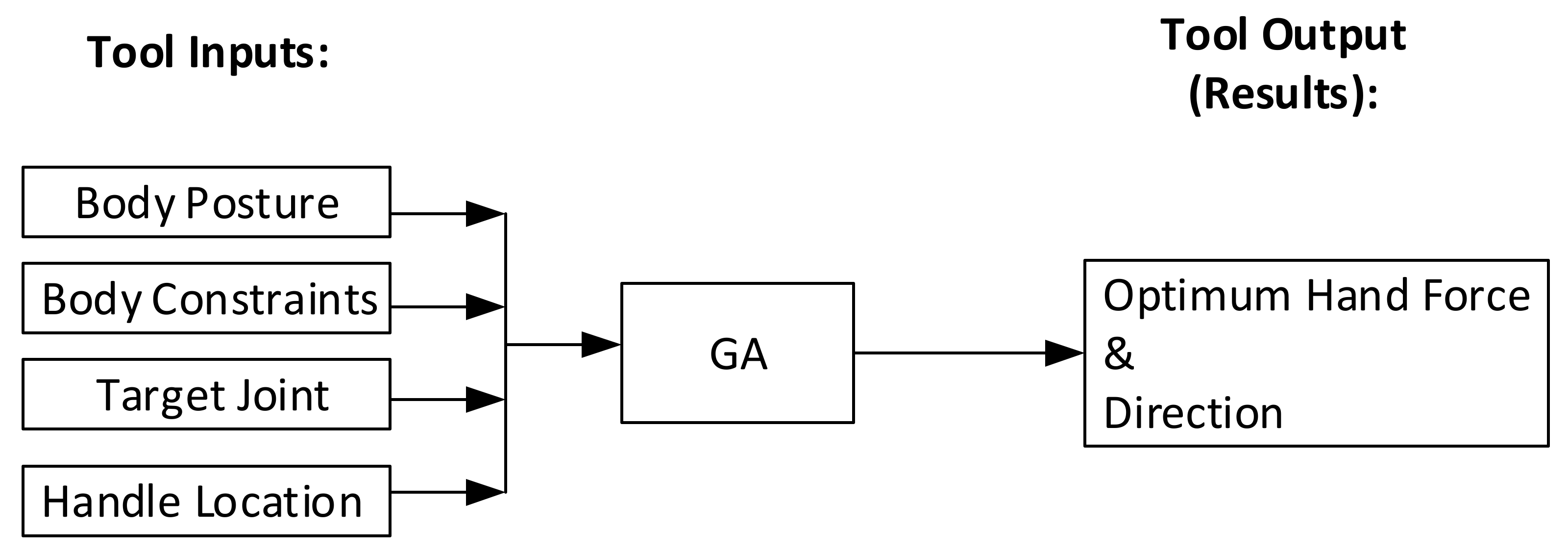
In order to measure the effect of different handle locations on reducing knee torque, a theoretical tool (
Figure 1) was developed by integrating an optimization technique (Genetic Algorithm) with the equilibrium equation for the above-knee body.
2.1. Kinetic Model Derivation
To ensure the safety of the transition, momentum was not considered and subjects were required to perform the transition as steadily as possible. In this regard, the force equilibrium equations along the X and Z axes, in addition to the torque equilibrium equation around the Y axis, needed to be derived for rigid bodies (each body made of several different body segments) to obtain the torques.
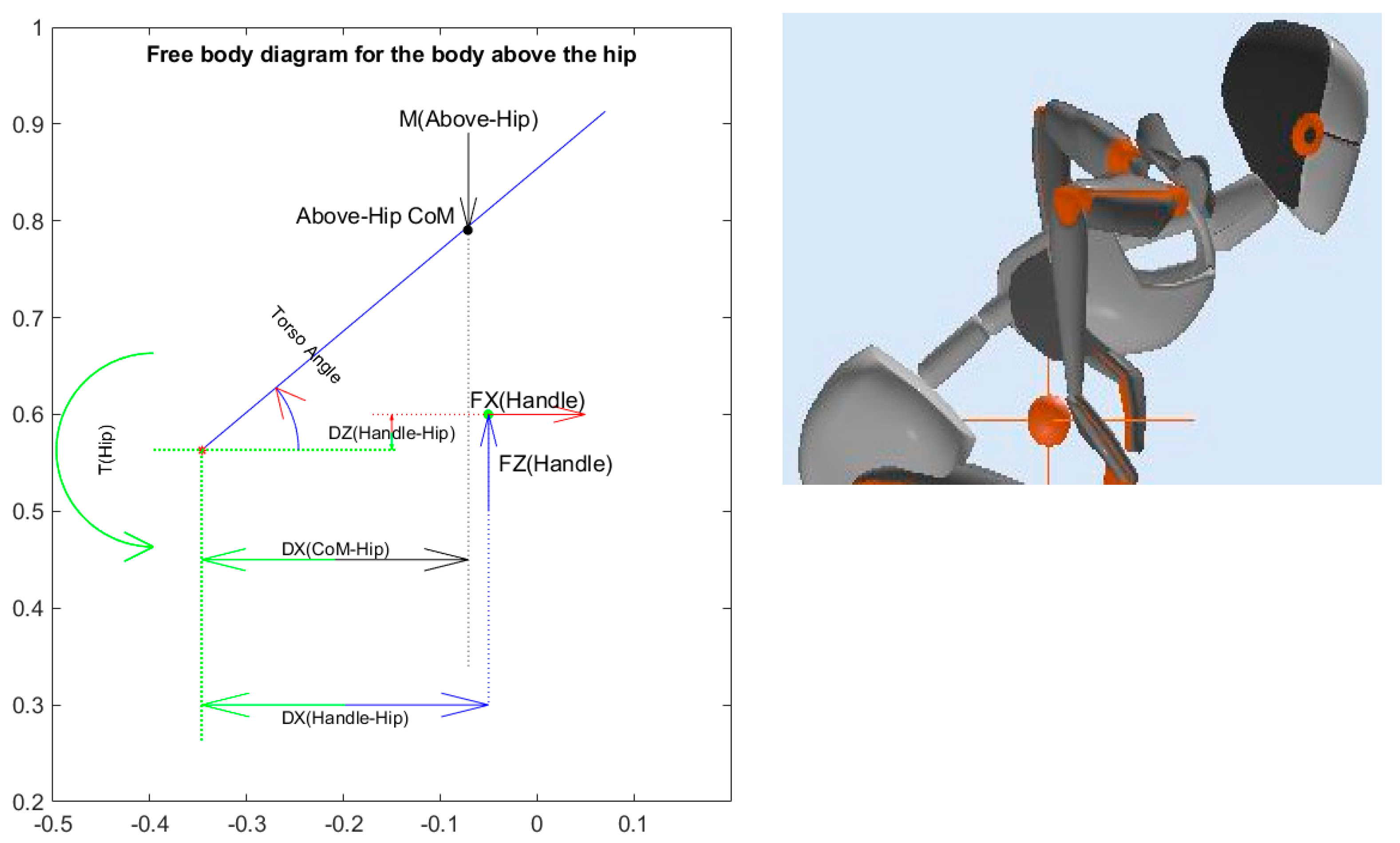
2.1.1. Hip Torque Calculations
To calculate torque at the hip joint, the thigh is assumed to be fixed in space as shown in
Figure 2.
The torque of the hip joint was calculated by employing the equilibrium equations on the free body diagram of the body above the hip, as shown in
Figure 2:
The mass used in Equation (1) is the mass of the upper body.
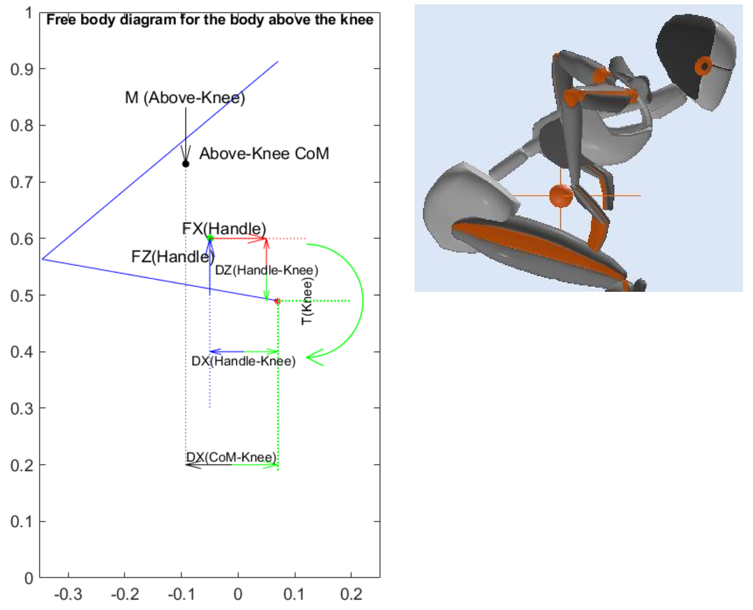
2.1.2. Knee Torque
During the STS transition, the knee joint must compensate for the effect of body mass on the knee joint. To calculate torque generation at the knee joint, the lower leg is assumed to be fixed in space so as to examine only the torque generated in the knee joint, as shown in
Figure 3.
The torque at the knee joint was calculated by employing the equilibrium equations on the free body diagram of the body above the knee, as shown in
Figure 3:
The mass used in Equation (2) is the mass of body above the knee.
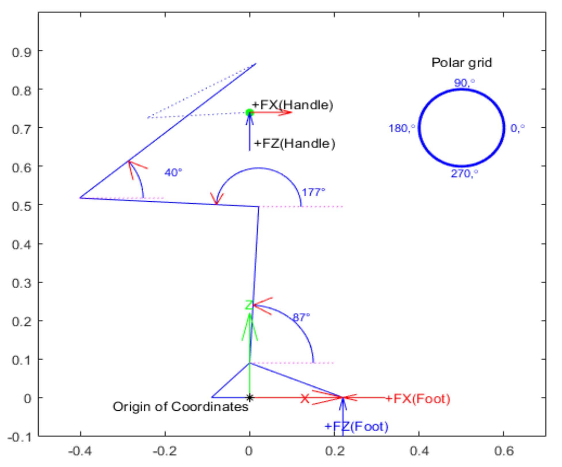
The green curved arrow in
Figure 3 shows the positive direction of the knee torque. The torque induced by the body mass on the knee joint is anticlockwise (shown using black arrows). Both vertical and horizontal handle forces (FZ and FX), shown using blue and red arrows, provide anticlockwise assisting torque to the knee joint and consequently reduce the torque required of the muscles at this joint (shown using blue and red curved torque arrows at the knee joint).
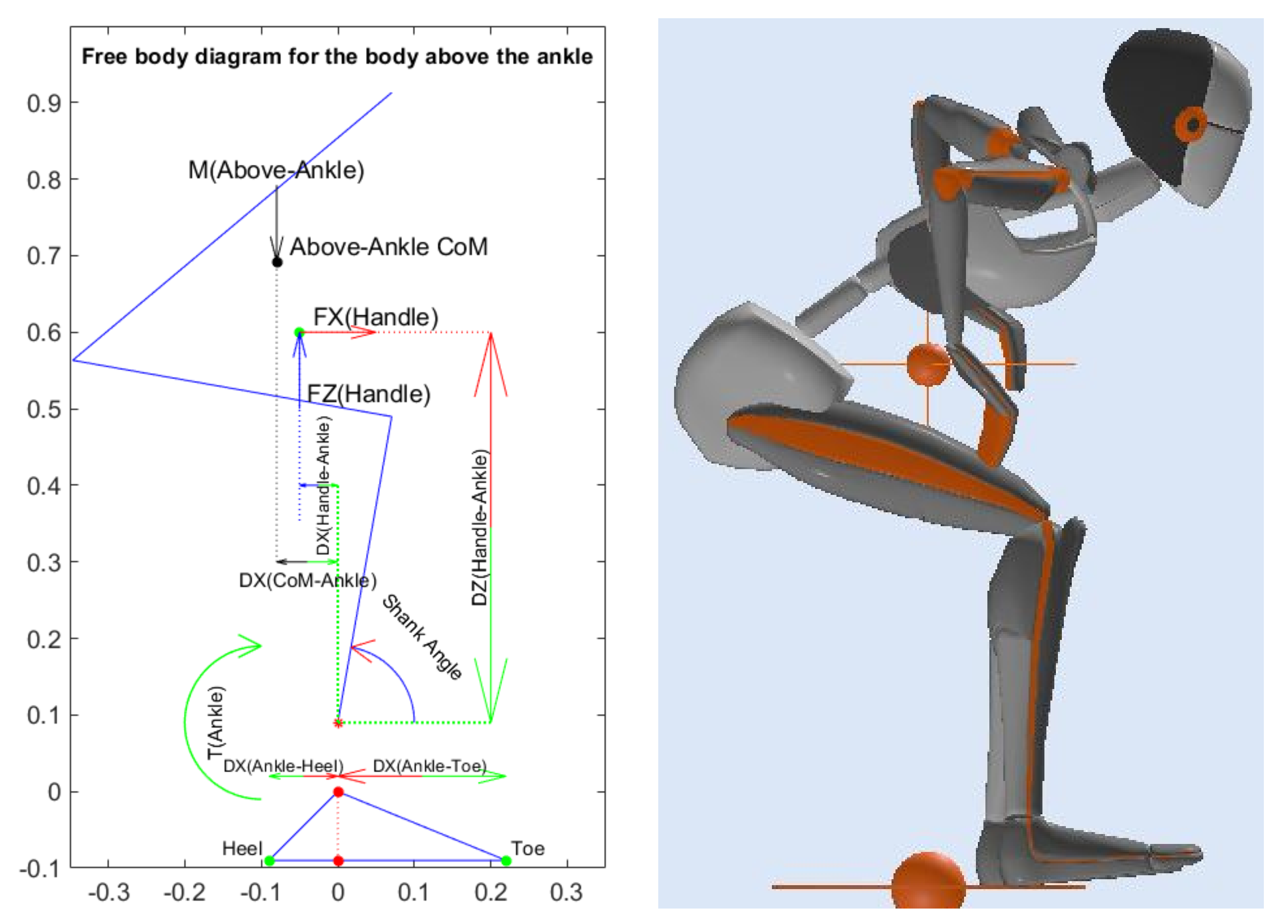
2.1.3. Ankle Joint Calculations
The ankle joints play a significant role not only in the STS transition but in almost all body activities. The ankle joint is responsible for maintaining balance during any body motion when interacting with the ground, especially when standing.
The torque and reaction forces at the ankle joint were calculated by employing the equilibrium equations on the free body diagram of the body above the ankle shown in
Figure 4:
The mass used in Equation (3) is the mass of the body above the ankle.
2.2. Optimization Plan
This study identified the knee joint as the most limiting factor in the STS transition. In this regard, minimising the knee torque required is the main concern.
2.2.1. Objective
The target is to find the minimum components of hand force required to minimise the knee torque the subject has to provide for STS transition at the seat-off point. This target is represented by two objective functions:
The first objective function was calculated to minimise the resultant hand force as:
The second objective function was calculated using Equation (5) to reduce the knee torque required as:
2.2.2. Proposed Constraints and Assumptions
The constraints and assumptions encountered while performing the optimization process are as indicated below:
- 2.
Assume the maximum available knee and hip torques occur when the subject can just hold the seat-off posture with hands on knees. This was calculated at 5.4 Kgm for each knee joint for the subjects who were tested.
- 3.
Assume that hip torque cannot be more than 7.36 Kgm (the maximum available hip torque noted in assumption 2 above):
- 4.
The seat-off posture employed for the theoretical tool developed in this study was based on the nose-over-toes or full trunk flexion strategy (as shown in
Figure 5), where:
- 5.
Assume the hand assistance force is the result of vertical and horizontal forces, as expressed in Equation (4).
- 6.
Assume (based on analysis) that each hand can provide a maximum of 20 Kg resultant force:
- 7.
The potential handle locations are accessible.
Figure 5.
Seat-off posture employed in the theoretical tool.
Figure 5.
Seat-off posture employed in the theoretical tool.
2.2.3. Definition of Optimum Handle Position
The optimum handle position has the smallest resultant handle force required to achieve the minimum knee torque requirement. In this regard, the theoretical tool developed in this study used the knee joint as the target joint to reduce its torque requirement while maintaining the torque requirements at the hip and ankle joint within the limits.
3. Results
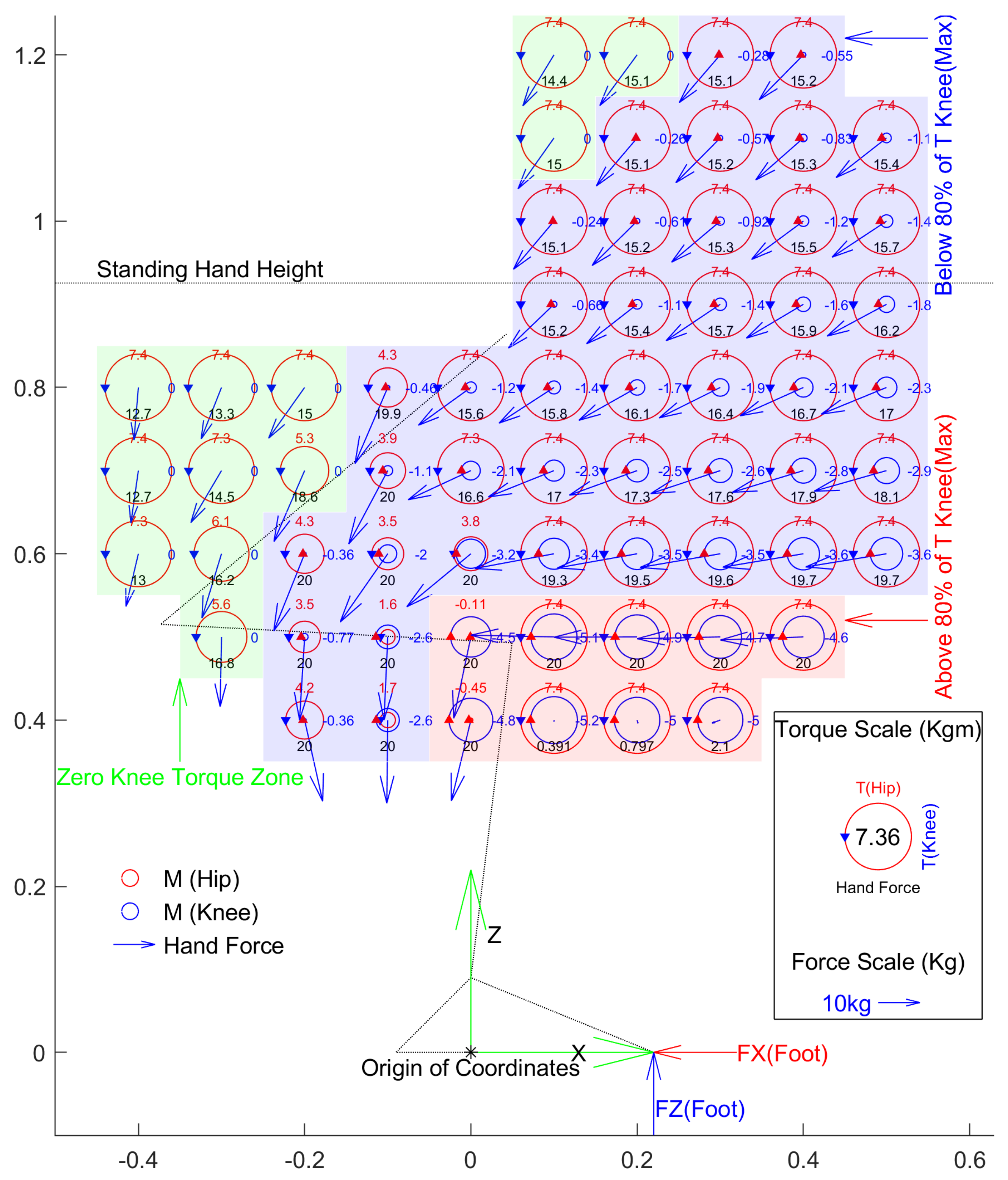
Figure 6 shows the minimum hand force needed to achieve minimum knee torque at the seat-off point by taking balance into account for a subject with a weight of 76 Kg. Balance is achieved by a combination of hand force and ankle torque. The range of ankle torque is limited by muscle strength and foot size. For this purpose, it is assumed that ankle torque is enough for the person to stand on the heel or toe of both feet at once. In this regard, the position of the ground reaction force needs to be within the length of the foot.
3.1. Limitation of Handle Zone
The handle locations shaded in red (shown in
Figure 6) reduced the knee torque by 20%. These handle locations require the largest hip torques due to the required upward vertical hand forces. Consequently, these handle locations are excluded from the potential handle locations.
3.2. Handle Zones
The locations of handles can be divided into different zones based on the position of body joints. During the STS task, as the body joints are positioned in different places, hand force application can assist or oppose the body joints. Each component of hand force can provide clockwise or anti-clockwise torque depending on the handle location in any of the 4 quadrants around the joint.
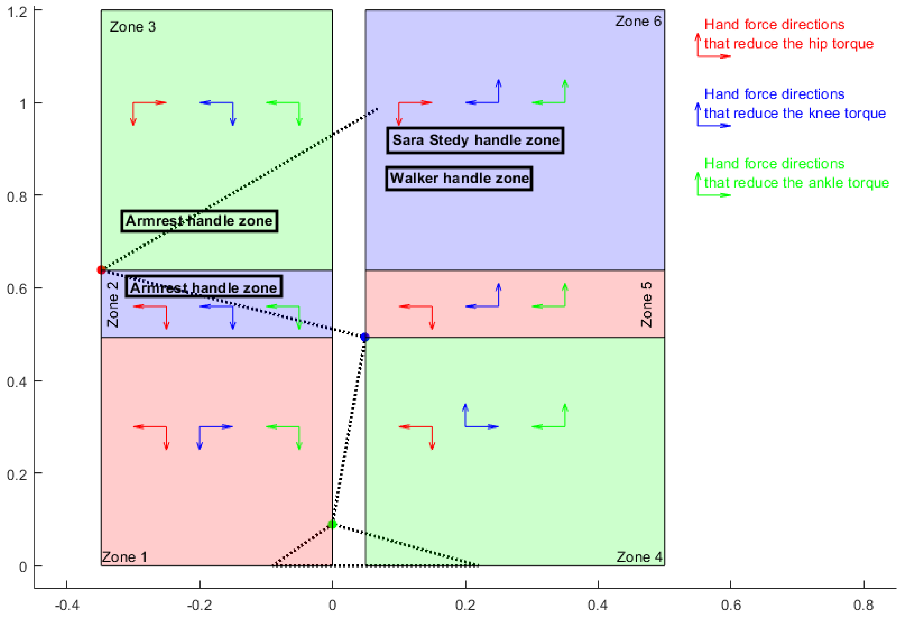
Figure 7 was derived to summarise the directions of each component of hand force that provides assisting torque to the knee (clockwise), hip (anti-clockwise) and ankle (clockwise) joints, reducing the torque requirements at these joints.
Arrows in each zone show the contributing directions of each component of hand force providing assisting torque to the hip, knee and ankle joints (blue for knee, red for hip and green for ankle). For example, for a handle placement in zone 1, backward horizontal hand force reduces hip and ankle torque while increasing the knee torque requirement. In addition, within this zone, applying downward vertical hand force assists the hip, knee and ankle joints and reduces torque requirements in both joints.
4. Discussion
There are few analyses of two-arm assisted STS transitions in older adults. Most of these studies measured the effect of a fixed handle location on the biomechanics of the STS transition [
10,
28,
29] and have not measured the effect of different handle locations. There is only one study, by Kinoshita [
30], that measured the effect of handrail height at two different heights and showed that the combined high and low positions recorded the minimum physical load required during STS transition. These papers used handrails at a fixed height and took the effect of grip position and trunk-tilt angle into account. Xiaolong Han and Xue [
14] is the only study that has measured the effect of two grip positions and trunk-tilt angles at the seat-off point and found that the minimum knee torque occurred with a trunk-tilt angle of 30 degrees and grip positioned above the greater trochanter beneath the chest.
In summary, all research on two-arm assisted STS transition has concentrated on biomechanical comparisons of a specific group of subjects in real-life in reaction to the limited fixed handrails. None of the studies have looked at finding the optimum handle location for an individual. This study developed a theoretical tool that enables us to identify the best handle location for a specific individual based on their body constraints (e.g., maximum available hip/knee/ankle torques, hand force limit) to receive the optimum hand assistance at the critical or challenging point the person is faced with (e.g., seat-off point, initiation point).
The tool developed in this research focuses on the study of the biomechanics of transition at the seat-off point, which is typically the most difficult point of transition.
However, this means that the study does not include the required body strength and motion for the whole transition.
The kinetic parameters studied in this research were limited to the required torques at the body joints at a defined seat-off posture. These kinetic parameters do not represent the required power, not only at the defined point but also during the whole transition.
The optimum hand location in this study was assumed to be fixed during the whole transition, although the body’s CoM is continually moving during the transition. Having an adjustable handle, or multiple handle locations, could help to compensate for the moving CoM during the transition. This study has not addressed these issues and they are left for future studies.
4.1. Contribution of Assistive Devices to the STS Transition
Figure 7 also shows the handle locations of some of the available assistive devices.
The kinetic parameters of these handle locations at the seat-off point are normalised by body mass (BM) in
Table 1.
Assistive devices deliver different levels of hand assistance to users depending on handle placement. Comparing the use of armrests on standard chairs, walkers and Sara Stedy showed that chair armrests provide the most assistance.
4.2. Recommended Future Work
In general, the following could be considered for future research:
Make available a user-friendly tool or app that allows practitioners to produce handle location maps for individual patients.
Examine the best handle position for the whole STS transition, not just the seat-off point and consider adjustable handle locations over the whole transition to find the optimum handle trajectory.
Validate the current tool map with real patients and real handle positions through experimental set-up.
Validate the current tool map for people with particular weaknesses.
Employ the tool to study the contribution of different assistive devices to people with particular strengths.
5. Conclusions
The best handle locations requiring the minimum torques are placed in handle zone 2 (see
Figure 7). Within this zone, the assisting directions of both horizontal and vertical hand forces to the ankle, hip, and knee joints are the same: vertically downward and horizontally backward. This means that, with handle placements in this zone, subjects can get assistance from both vertical and horizontal components of hand forces for all joints. The best handle location is zone 2, requiring the minimum torques at the body joint horizontally placed between 0.3 m and 0.1 m behind the ankle and vertically 0.5 m above ground level.
Seat and armrest support can be used as handle locations at this point. However, although the seat-off point is the most challenging point of transition, it is not the only failing point that people might face during the task, and it is worth noting that the highlighted handle locations become inaccessible as the person rises, and so do not contribute to task completion past the seat-off point. The tool developed in this study enables us to examine additional failing points (postures) for each person so as to find the best handle locations.
The tool developed in this study can be practically used by medical staff, especially occupational therapists, to find the best handle location and handle zone for their patients based on their body constraints and strengths.
Author Contributions
Conceptualization, A.B. and K.A.; Formal analysis, A.B. and K.A.; Investigation, A.B.; Methodology, A.B.; Project administration, A.B. and A.B.; Resources, A.B. and K.A.; Supervision, K.A.; Validation, A.B. and K.A.; Visualization, A.B.; Writing—original draft, A.B.; Writing—review and editing, A.B. and K.A. All authors have read and agreed to the published version of the manuscript.
Funding
This research is a consequence of funding from Enztec Ltd., that awarded me the PhD scholarship with Callaghan Innovation.
Conflicts of Interest
The authors declare no conflict of interest.
References
- Evans, R.G.; McGrail, K.M.; Morgan, S.G.; Barer, M.L.; Hertzman, C. Apocalypse no: Population aging and the future of health care systems. Can. J. Aging Rev. Can. Vieil. 2001, 20, 160–191. [Google Scholar] [CrossRef] [Green Version]
- Palmer, R.M.; Landefeld, C.S.; Kresevic, D.; Kowal, J. A medical unit for the acute care of the elderly. J. Am. Geriatr. Soc. 1994, 42, 545–552. [Google Scholar] [CrossRef] [PubMed]
- Covinsky, K.E.; Palmer, R.M.; Kresevic, D.M.; Kahana, E.; Counsell, S.R.; Fortinsky, R.H.; Landefeld, C.S. Improving functional outcomes in older patients: Lessons from an acute care for elders unit. Jt. Comm. J. Qual. Patient Saf. 1998, 24, 63–76. [Google Scholar] [CrossRef] [PubMed]
- Covinsky, K.E.; Justice, A.C.; Rosenthal, G.E.; Palmer, R.M.; Landefeld, C.S. Measuring prognosis and case mix in hospitalized elders: The importance of functional status. J. Gen. Intern. Med. 1997, 12, 203–208. [Google Scholar] [PubMed] [Green Version]
- Fortinsky, R.H.; Covinsky, K.E.; Palmer, R.M.; Landefeld, C.S. Effects of functional status changes before and during hospitalization on nursing home admission of older adults. J. Gerontol. Ser. A Biomed. Sci. Med. Sci. 1999, 54, M521–M526. [Google Scholar] [CrossRef] [PubMed]
- Inouye, S.K.; Peduzzi, P.N.; Robison, J.T.; Hughes, J.S.; Horwitz, R.I.; Concato, J. Importance of functional measures in predicting mortality among older hospitalized patients. JAMA 1998, 279, 1187–1193. [Google Scholar] [CrossRef] [Green Version]
- Covinsky, K.E.; Wu, A.W.; Landefeld, C.S.; Connors, A.F., Jr.; Phillips, R.S.; Tsevat, J.; Dawson, N.V.; Lynn, J.; Fortinsky, R.H. Health status versus quality of life in older patients: Does the distinction matter? Am. J. Med. 1999, 106, 435–440. [Google Scholar] [CrossRef]
- Otago University. Injury Prevention Research Unit. Available online: https://blogs.otago.ac.nz/ipru/ (accessed on 2 January 2023).
- Arborelius, U.P.; Wretenberg, P.; Lindberg, F. The effects of armrests and high seat heights on lower-limb joint load and muscular activity during sitting and rising. Ergonomics 1992, 35, 1377–1391. [Google Scholar] [CrossRef]
- Smith, S.H.L.; Reilly, P.; Bull, A.M.J. A musculoskeletal modelling approach to explain sit-to-stand difficulties in older people due to changes in muscle recruitment and movement strategies. J. Biomech. 2020, 98, 109451. [Google Scholar] [CrossRef]
- Kinoshita, S.; Kiyama, R.; Yoshimoto, Y. Effect of handrail height on sit-to-stand movement. PLoS ONE 2015, 10, e0133747. [Google Scholar] [CrossRef] [Green Version]
- Mak, M.K.Y.; Levin, O.; Mizrahi, J.; Hui-Chan, C.W.Y. Joint torques during sit-to-stand in healthy subjects and people with Parkinson’s disease. Clin. Biomech. 2003, 18, 197–206. [Google Scholar] [CrossRef]
- Papa, E.; Cappozzo, A. Sit-to-stand motor strategies investigated in able-bodied young and elderly subjects. J. Biomech. 2000, 33, 1113–1122. [Google Scholar] [CrossRef]
- Han, X.B.; Xue, Q. Effect of different handrail types and seat heights on kinematics and plantar pressure during STS in healthy young adults. Medicine 2021, 100, e28091. [Google Scholar] [CrossRef]
- Roy, G.; Nadeau, S.; Gravel, D.; Piotte, F.; Malouin, F.; McFadyen, B.J. Side difference in the hip and knee joint moments during sit-to-stand and stand-to-sit tasks in individuals with hemiparesis. Clin. Biomech. 2007, 22, 795–804. [Google Scholar] [CrossRef] [PubMed]
- Bohannon, R.W. Knee extension strength and body weight determine sit-to-stand independence after stroke. Physiother. Theory Pract. 2007, 23, 291–297. [Google Scholar] [CrossRef] [PubMed]
- Ikezoe, T.; Asakawa, Y.; Hazaki, K.; Kuroki, H.; Morinaga, T.; Kawano, I.; Kanzaki, H.; Aoki, N. Muscle strength and muscle endurance required for independent walking in the elderly. J. Phys. Ther. Sci. 1997, 9, 19–22. [Google Scholar] [CrossRef] [Green Version]
- Bohannon, R.W. Alternatives for measuring knee extension strength of the elderly at home. Clin. Rehabil. 1998, 12, 434–440. [Google Scholar] [CrossRef]
- Schenkman, M.; Hughes, M.A.; Samsa, G.; Studenski, S. The relative importance of strength and balance in chair rise by functionally impaired older individuals. J. Am. Geriatr. Soc. 1996, 44, 1441–1446. [Google Scholar] [CrossRef]
- Alexander, N.B.; Schultz, A.B.; Warwick, D.N. Rising from a chair: Effects of age and functional ability on performance biomechanics. J. Gerontol. 1991, 46, M91–M98. [Google Scholar] [CrossRef] [PubMed]
- Fukagawa, N.K.; Brown, M.; Sinacore, D.R.; Host, H.H. The relationship of strength to function in the older adult. J. Gerontol. Ser. A Biol. Sci. Med. Sci. 1995, 50, 55–59. [Google Scholar] [CrossRef]
- Ploutz-Snyder, L.L.; Manini, T.; Ploutz-Snyder, R.J.; Wolf, D.A. Functionally relevant thresholds of quadriceps femoris strength. J. Gerontol. Ser. A Biol. Sci. Med. Sci. 2002, 57, B144–B152. [Google Scholar] [CrossRef]
- Eriksrud, O.; Bohannon, R.W. Relationship of knee extension force to independence in sit-to-stand performance in patients receiving acute rehabilitation. Phys. Ther. 2003, 83, 544–551. [Google Scholar] [CrossRef] [PubMed] [Green Version]
- Bohannon, R.W. Body Weight-Normalized Knee Extension Strength Explains Sit-to-Stand Independence: A Validation Study. J. Strength Cond. Res. 2009, 23, 309–311. [Google Scholar] [CrossRef] [PubMed]
- Salem, G.J.; Wang, M.-Y.; Young, J.T.; Marion, M.; Greendale, G.A. Knee strength and lower-and higher-intensity functional performance in older adults. Med. Sci. Sport. Exerc. 2000, 32, 1679–1684. [Google Scholar] [CrossRef]
- Lomaglio, M.J.; Eng, J.J. Muscle strength and weight-bearing symmetry relate to sit-to-stand performance in individuals with stroke. Gait Posture 2005, 22, 126–131. [Google Scholar] [CrossRef] [PubMed] [Green Version]
- Lord, S.R.; Murray, S.M.; Chapman, K.; Munro, B.; Tiedemann, A. Sit-to-stand performance depends on sensation, speed, balance, and psychological status in addition to strength in older people. J. Gerontol. Ser. A Biol. Sci. Med. Sci. 2002, 57, M539–M543. [Google Scholar] [CrossRef] [PubMed]
- Chang, S.R.; Kobetic, R.; Triolo, R.J. Understanding stand-to-sit maneuver: Implications for motor system neuroprostheses after paralysis. J. Rehabil. Res. Dev. 2014, 51, 1339. [Google Scholar] [CrossRef]
- Bahrami, F.; Riener, R.; Jabedar-Maralani, P.; Schmidt, G. Biomechanical analysis of sit-to-stand transfer in healthy and paraplegic subjects. Clin. Biomech. 2000, 15, 123–133. [Google Scholar] [CrossRef]
- Kinoshita, S. Handrail position and shape that best facilitate sit-to-stand movement. J. Back Musculoskelet. Rehabil. 2012, 25, 33–45. [Google Scholar] [CrossRef]
| Disclaimer/Publisher’s Note: The statements, opinions and data contained in all publications are solely those of the individual author(s) and contributor(s) and not of MDPI and/or the editor(s). MDPI and/or the editor(s) disclaim responsibility for any injury to people or property resulting from any ideas, methods, instructions or products referred to in the content. |
© 2023 by the authors. Licensee MDPI, Basel, Switzerland. This article is an open access article distributed under the terms and conditions of the Creative Commons Attribution (CC BY) license (https://creativecommons.org/licenses/by/4.0/).


