Article

Nanoimprinted Hierarchical Micro-/Nanostructured Substrates for the Growth of Cardiomyocyte Fibers

1
PROFACTOR GmbH, Im Stadtgut D1, 4407 Steyr-Gleink, Austria
2
IMBA, Institute of Molecular Biotechnology of the Austrian Academy of Sciences, Dr. Bohr-Gasse 3, 1030 Vienna, Austria
3
Vienna BioCenter Ph.D. Program, Doctoral School of the University of Vienna, Medical University of Vienna, 1030 Vienna, Austria
4
Institute of Solid State Electronics, Technische Universität Wien, Karlsplatz 13m, 1040 Vienna, Austria
5
ChanPharm GmbH, Leidesdorfgasse 14, TOP 6, 1190 Vienna, Austria
6
Division of Pharmacology and Toxicology, University of Vienna, Josef-Holaubek-Platz 2, 1090 Vienna, Austria
7
STENSBORG A/S, Risø Huse 50, 4000 Roskilde, Denmark
*
Author to whom correspondence should be addressed.
Nanomanufacturing 2023, 3(4), 416-433; https://doi.org/10.3390/nanomanufacturing3040026
Submission received: 12 July 2023 / Revised: 5 September 2023 / Accepted: 25 September 2023 / Published: 7 November 2023
(This article belongs to the Special Issue Nanoimprinting and Sustainability)

Abstract

:
Investigating the behavior of cardiomyocytes is an important part of drug development. We present a structure and a related nanoimprint-based fabrication method, where the cardiomyocytes form isolated fibers, which is beneficial for drug testing, more closely representing the structure of the cardiomyocytes in vivo. We found that channel structures with walls with a rough top surface stimulate cardiomyocytes to form such fibers, as desired. Nanoimprint lithography is used as a fast and cost-efficient method to fabricate our hierarchically structured cell growth substrates.

1. Introduction

Advanced cell array technologies (e.g., multielectrode arrays, microelectrode arrays (MEAs) [1] or planar patch clamp [2,3]) have emerged as novel standards for studying in vitro cardiovascular, neurological and other diseases and for developing novel drugs to treat them. The application of these technologies to human-stem-cell-derived tissues enables drug discovery and drug safety studies on human preparations. It is well established that cardiac and non-cardiac drugs can induce prolongation of the Q-T interval of the ECG and cause arrhythmias [4,5]. Screening for cardiotoxic drug effects therefore became part of the routine process in drug development and a requirement of regulatory authorities. The estimation of pro-arrhythmic effects of drug candidates can reduce risk, time and costs for companies. We use human-pluripotent-stem-cell-derived cardiomyocytes (hPSC-CMs) [6] in this study. To be able to perform reliable and significant measurements, we wanted the hPSC-CMs to form fibers that were isolated from each other on planar substrates. The reason why we wanted to have cardiomyocyte fibers is as follows: Currently, toxicological studies and drug screening on ionic channels of myocardial cells are commonly performed on two-dimensional (2 D) monolayer cell cultures. Cells in monolayers are, however, connected stochastically, leading to random propagation of the action potentials. In contrast, in the myocardium, excitation is propagated faster longitudinally along fiber structures than parallel to the fiber orientation (anisotropy). The results of pharmacological studies on monolayers with stochastically connected muscle cells (i.e., drug effects on unstructured 2 D cultures) thus cannot be simply transferred to an in vivo-like situation. An alignment of cells in grooves additionally enables contraction measurements along the fiber axis, which is closer to the situation in myocardial tissue. hPSC-CMs are either derived by reprogramming somatic human cells (hiPSCs, human induced pluripotent stem cells) or from blastocysts (hESCs, human embryonic stem cells). Human PSCs can self-renew in vitro while remaining genetically stable, are highly tractable using genome editing technologies and can differentiate into all cell types of the human body, including cardiomyocytes (hPSCs-CMs) [7,8,9,10]. Major advantages of hPSC derivatives over animal models include their human origin (making them more representative for drug development), the virtually unlimited supply of cells from different human genetic backgrounds and the potential to reduce the number of laboratory animals and testing. More recently, hPSCs have been used to push further the modeling of human heart formation via the generation of cardiac organoids (cardioids) [6]. We use iPSC cardiomyocytes (iPSCs–CM) because they can be differentiated into different subtypes of myocardial cells (atrial, ventricular, sinus node cells). This would enable studies of atrial, ventricular, etc., fibers for the first time.
It is well known that not only materials, but also certain micro- and nanostructured surfaces, can influence the adhesion, orientation and growth of cells on surfaces (e.g., [11,12,13,14]); in particular, structures in the same size region as the cells could cause a guidance of the cells. It has been shown that line and space structures could assist in aligning cells (e.g., [15]). Recently, it has also been shown for hPSC-CMs that line and space structures are helpful for fiber formation [16]. In this work, we focus on the mastering, replication and testing of hierarchical structures, as well as their influence on cardiomyocyte growth. Here, the term “hierarchical” stands for larger structures with smaller structures superimposed, for example structures of several micrometers in dimension with sub-µm structures on top, like, e.g., in references [17,18,19,20]. We present a micro- and nanostructured substrate fabricated using nanoimprinting, where the CMs form isolated fibers. None of the marketed screening technologies on myocardial cells currently account, however, for such “tissue-like” structures. The development of this fiber chip technology is expected to substantially improve drug safety and drug discovery investigations.
Our fabrication method is based on nanoimprint lithography (NIL) (e.g., [21,22,23,24,25]), since it is a scalable, mass-fabrication-suited method for the cost-efficient replication of micro- and nanostructures. NIL has been shown to be able to provide complex micro- and nanotopographies in a single processing step (e.g., [26,27,28,29]), as well as the direct structuring of biocompatible materials (e.g., [30,31,32,33,34]). For nanoimprinting, a master structure is always necessary, and from which a stamp is typically replicated, which contains the negative features of the original master structure. When using this stamp in a nanoimprint process, micro/nanotopography is created which replicates the structures of the original master with the same polarity.
In vitro testing to reduce the amount of animal testing is one of the motivations for our work. Cell cultures are already an important part in the drug discovery and drug development process. Providing better substrates for cell growth, and allowing the in vitro tests to be closer to the real tissue, will improve the quality of the test outcomes and will reduce the need for animal testing, paving the way for improved sustainability in this process.
Furthermore, as will be discussed below, we think that nanoimprinting will provide a good and sustainable method for manufacturing cell growth substrates.

2. Materials and Methods

2.1. Structure Design

The goal of the work presented here is to provide a substrate that can on the one hand be fabricated in a cost-efficient way and on the other hand promote the formation of cardiomyocyte fibers. It seems likely that a surface structure with channels should be beneficial for this purpose. We chose channel dimensions in the range of what could be expected for cardiomyocyte fibers. To enhance the difference between different regions in the pattern, we included roughness in our design. It could be expected that this should have increased the probability of the individual fibers forming with only a certain distance between each other.

2.2. Nanoimprint Master Fabrication

The master structure for our work was prepared in silicon via photolithography and reactive ion etching. First, photolithography was carried out to pattern the substrate with various line and space structures with periods ranging from 20 µm to 60 µm, using contact exposure with a Cr-hard mask on a Suess MJB3 with AZ 5214 E (MicroChemicals GmbH, Ulm, Germany) as the photoresist. The silicon substrate was coated with 10 nm Cr and 240 nm Au via sputter deposition (Von Ardenne, Dresden, Germany LS 320 S, Cr: 100 W, 30 s, Au: 25 W, 350 s). The line and space patterns were transferred to the substrate via a lift-off step. The reactive ion etching process (Oxford Instruments, Abingdon, UK—PlasmaLab 100, Step 1: 90 min, 30 W, 1.31 × 10⁻² mbar, SF6 20 sccm, Ar 5 sccm, O2 5 sccm, Step 2: 2 min, 30 W, 0.12 mbar, SF6 20 sccm, Ar 5 sccm) was tuned to achieve a rough bottom of the channels produced in silicon. A hard mask structure of 250 nm Au on 10 nm Cr should have and did protect the underlying Si from reactive ion etching. The roughness of the bottom areas was achieved due to anisotropically etched surfaces analogous to black silicon. This roughness is the result of sub-micron features acting as a micro-mask for highly anisotropic etching. The origin of this micro-masking is still under debate [35] and may be (i) fluorocarbon-related debris originating from the fluorine etch gas [36,37], (ii) oxygen-related sources [38] such as silicon oxide formed in situ during etching or (iii) surface contaminations either from photoresist residues or from sputtered and redeposited hard mask material [39]. We speculate that redeposited gold from the hard mask may be the main cause of micro-masking. The ion milling component of the RIE process physically erodes not only the silicon but also the gold hard mask material. During RIE, the physical ion milling is well known to lead to the erosion of atoms from the material, but also the redeposition of sputtered atoms [40]. The sputter-eroded gold may redeposit on the sample again, as described in [41,42]: forward scattering from the sidewalls of the gold hard mask may redeposit in etch trenches and backscattering of the sputtered gold via collision with gas atoms in the plasma will redeposit small amounts of gold on more remote sample surfaces. The material redeposition during ion milling has been extensively studied and simulated [43], especially for focused ion beam milling [44] and for RIE [45]. To conclude, it is plausible that redeposited gold forms a nanoisland film [46] that acts as a micromask during anisotropic deep trench etching. Such gold nanoislands would mask the silicon beneath, so that the Au micromask generates the high roughness of the silicon surface. The fact that small pillars of Si also protrude from the sidewall of the trenches gives rise to our proposition that micromasking by redeposited gold eroded from the gold hard mask causes the high roughness of the silicon surface, as reported in [47]. For cell culture substrates, these corrugated trench floors proved to be ideal in preventing cell adhesion on the chip surface. The roughness on the bottom of the structures can clearly be seen in Figure 1, which shows SEM micrographs of different master structures produced using this process.

2.3. Nanoimprinting

2.3.1. Basics

From the master described above, stamps were replicated. For all of our samples, OrmoComp® (micro resist technology, Berlin, Germany [48]) was used as the nanoimprint material. It has excellent nanoimprint and optical properties and is known to be biocompatible (e.g., [13,14,30,49]), which was also verified in our experiments. We used different types of substrates, like PVC foils and glass, both in processes with and without a residual layer (see Section 3.1 below). Imprinting was performed at room temperature in a manual plate-to-plate manner as well as using the roll-to-plate (R2P) NIL tool from Stensborg A/S [50] (see Appendix A).

2.3.2. Stamps

For our nanoimprint processes, different kinds of stamps were used. For standard plate-to-plate nanoimprinting PDMS (poly dimethyl siloxane), stamps were used. In any stamp fabrication process, the polarity of the master is initially reversed. A first PDMS copy is produced by casting Sylgard 184 (1:10 mixing ratio) and curing it for 24 h at 40 °C, and from this copy another PDMS copy (again Sylgard 184) is created according to [51]. Both stamps were used for further nanoimprinting, resulting in samples where the roughness was either on the bottom of the trenches (first-copy stamp, imprint with the same polarity as the master) or on the top of the walls (second-copy stamp). Photographs of the master and first- and second-generation stamps can be found in Figure 2 below.
For roll-to-plate imprinting, an array of imprints is created first on a glass wafer (see Appendix A, Figure A2) using the first-copy stamp. The imprint material was OrmoComp®, which was manually dispensed using a Nordson Performus V dispenser (0.016″ cone, 0.74 bar, 0.2 s). From this intermediate large-area master, a PDMS stamp was fabricated after applying a BGL-GZ-83 anti-adhesion layer [52,53]. This large-area PDMS stamp containing 24 imprint fields was then used to create a printing plate for the R2P nanoimprinting process. Here, a 150 µm thick PVC foil was used as a backplane and OrmoClear®30 (micro resist technology GmbH) was used as the imprinting material. The OrmoClear®30 was manually dispensed (Nordson Performus V, 0.016″ cone, 2 bar, 2 s, 3 droplets per imprinting site) on each imprint site, and UV-curing was conducted at 385 nm. The PVC backplane was activated using O2 Plasma before the imprinting. The printing plate can be seen mounted in the R2P NIL tool in Figure A1 in Appendix A.

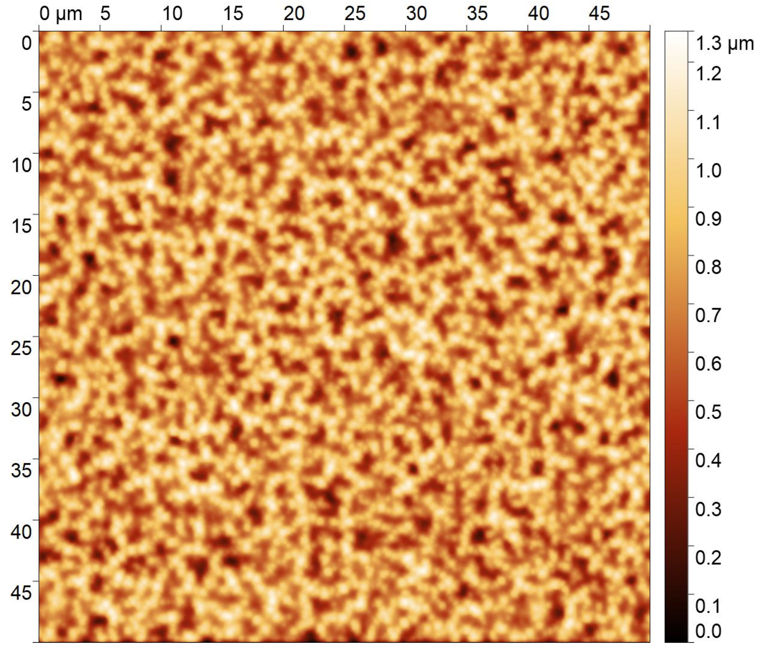
2.3.3. Imprinting Process, and Roughness on the Top or on the Bottom

Initially, while developing the nanoimprint process and also for the first experiments with cells, the samples were all fabricated using manual nanoimprinting with a single imprinted area (as compared with the 24 patterned areas in the R2P tool). A circular shape to fit into a 24-well plate was chosen as the substrate shape. Figure 3 shows a photograph of such a well plate where, in the two upper rows, nanoimprinted samples have been inserted. This concept provided the flexibility to quickly change the patterns and substrate material. As substrate materials, glass and PVC were used. Glass substrates (microscope cover glasses with a diameter of 15 mm, VWR, Vienna, Austria [54]) were cleaned with de-ionized water and acetone and oxygen plasma (Diener Plasma GmbH & Co. KG, Ebhausen, Germany nano [55]) before being coated with an adhesion promoter (HMNP-12, PROFACTOR GmbH, Steyr-Gleink, Austria [56]). OrmoComp® was manually dispensed onto the substrate and the PDMS stamp was also manually placed, taking care to avoid air bubble entrapment. For this process, no pressure in addition to that exerted by the capillary forces and gravity was applied. Curing was performed at 365 nm using a self-built UV-LED source. The whole process took place at room temperature. The separation of stamp and imprint was also conducted manually in a peeling-like motion. Both types of stamps were used in this way, resulting in samples with either the roughness on top or in the bottom of the channels. An optical micrograph of a sample with the roughness on the top of the channel walls can be seen in Figure 4a.

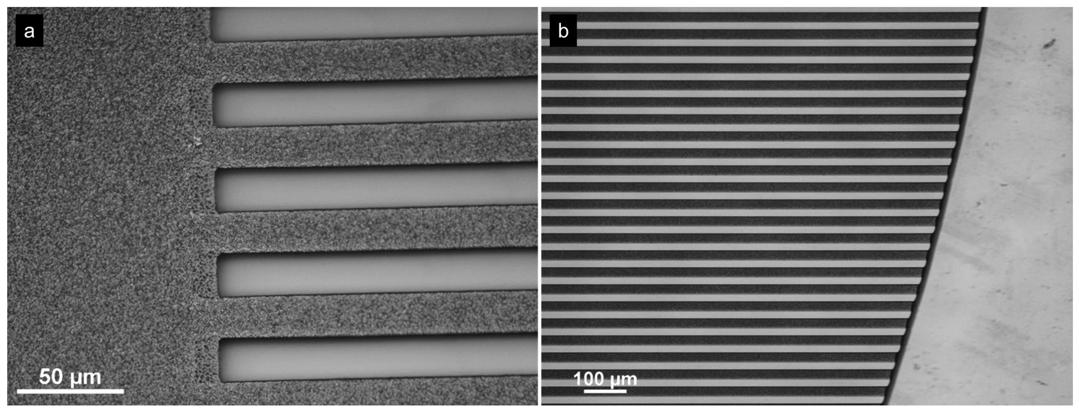
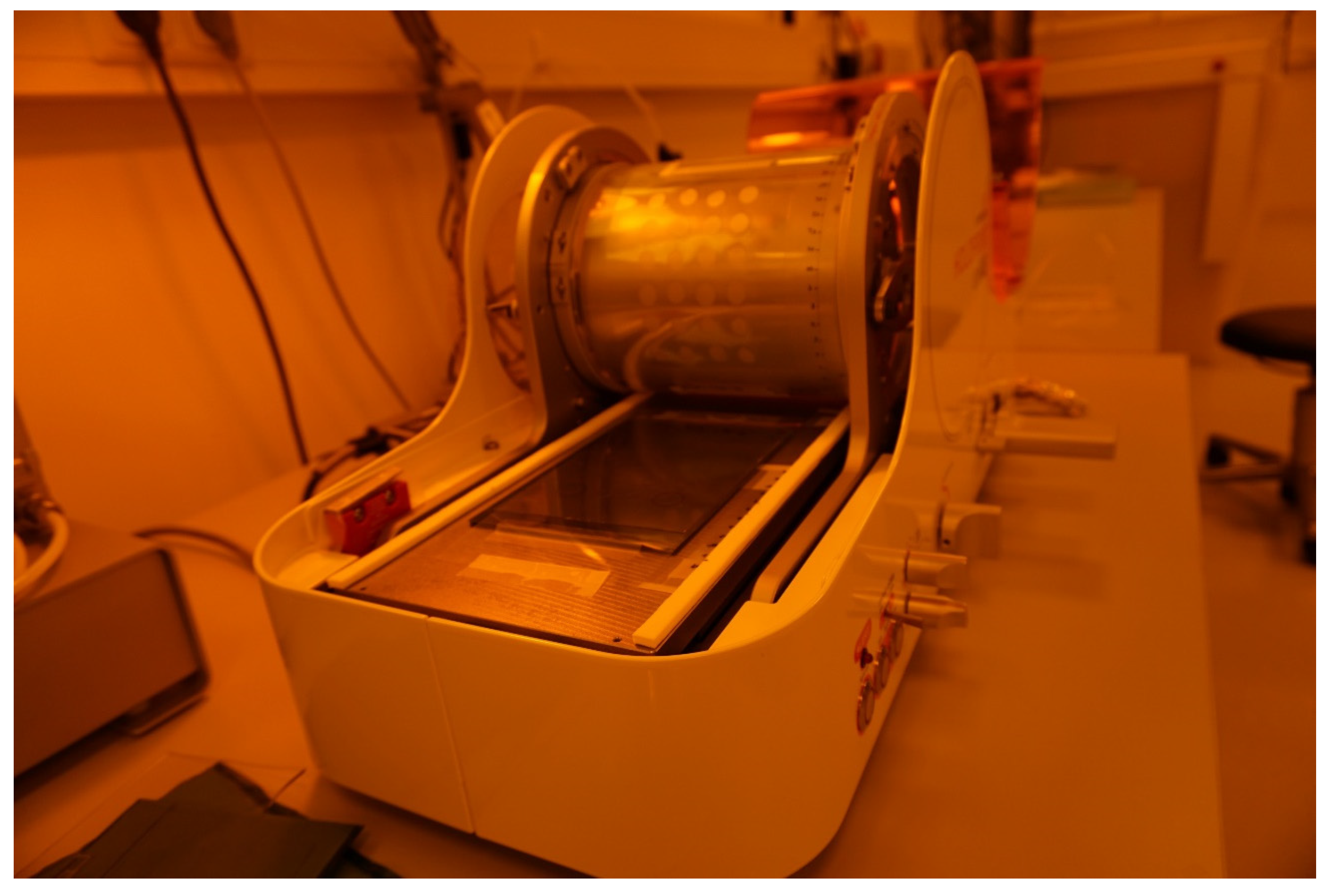
2.3.4. Roll-to-Plate Nanoimprinting

For the roll-to-plate nanoimprinting experiments, we used the STENSBORG Desktop R2P NanoImprinter [57] (Appendix A, Figure A1). It has an ideal size for well-plate-sized substrates. The maximum printing area in the tool is 100 × 150 mm2, while a well plate is 85 × 128 mm2 in size. The printing plate, as described above, is fixed on the roller using adhesive tape. The same PVC foils as for the manual imprints are used as substrates. In the roll-to-plate nanoimprinting process, UV-curing is conducted at room temperature in the nip, i.e., at the contact line, where the cylindrical roller and the substrate touch. The UV-LED wavelength is 395 nm. In the R2P tool, the imprinting force was adjusted in such a way that the roughness was faithfully replicated. Additional information on the R2P imprinting can be found in Appendix A.

2.4. Cells

The hPSCs cardiomyocytes were grown in a 3D organotypic structure, promoting more mature ion channel expression and morphological features [58]. To take advantage of these properties, cardiomyocytes were first grown in a 3D cardioid system according to the protocol in [6]. The cells were then dissociated from the organoids after day 10 using the CM dissociation kit (STEMCELL Technologies, Vancouver, Canada, #05025) for 7–10 min and centrifuging for 3 min at 130 g, and the cardiomyocytes were resuspended in CDM-I [6] with 5% FBS (PAA Laboratories, Cölbe, Germany, #A15-108) and 5 micromolar ROCK inhibitor. Cardiomyocytes were seeded at a density of 150,000 cells per surface inside a 24-well plate; after adding the cell suspension, the plate was shaken in orthogonal directions to ensure an even cell spread across the surface. On the subsequent day and every other day after, the cells were fed with CDM-I. Before seeding, substrates were sterilized with a 25 kGy dose of gamma irradiation, coated with laminin-511, 0.5 mg/cm2 diluted in DPBS, and incubated for 1 h at 37 °C. Alternatively, cells from a commercial supplier (ICell, Fujifile Cellular Dynamics, Madison, WI, USA [59]) were used which resulted in similar fiber formation in the grooves.

3. Results

3.1. Different Sample Geometries

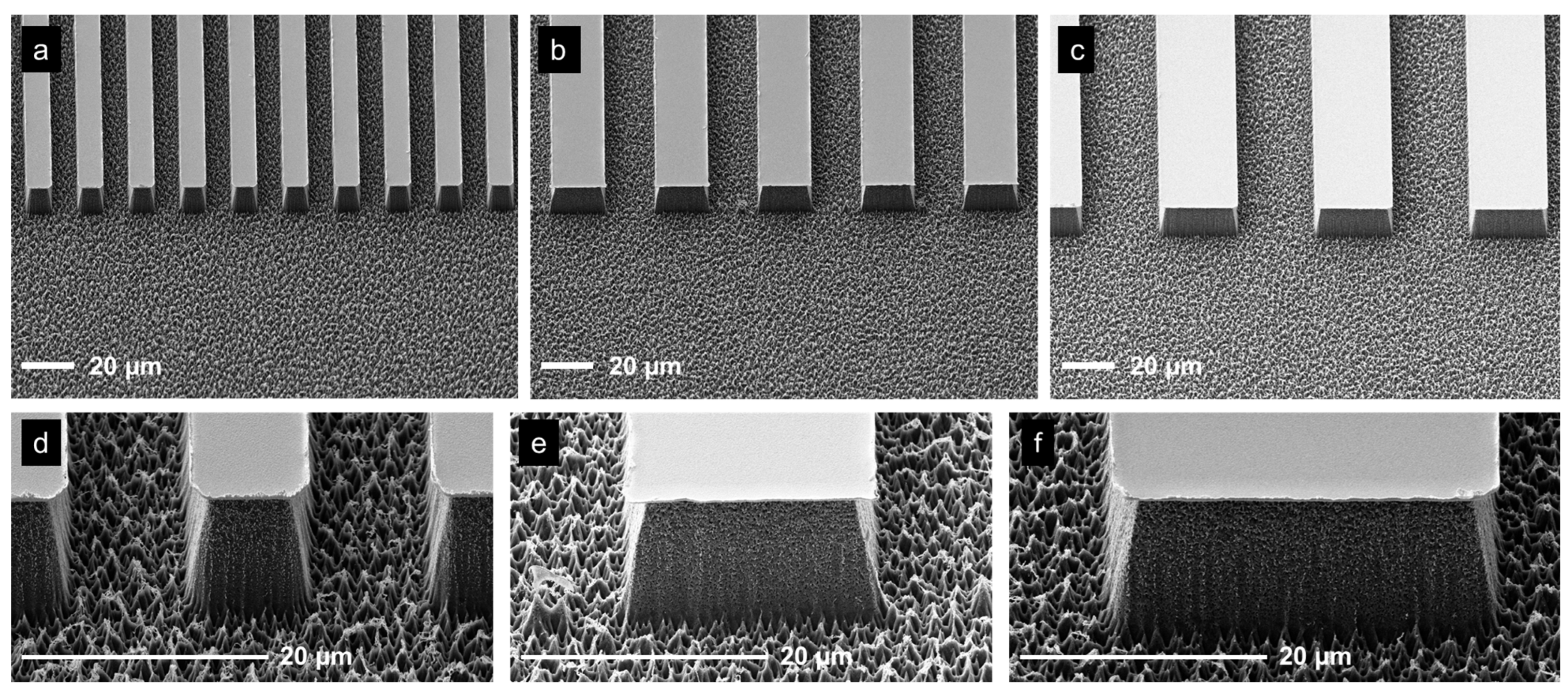
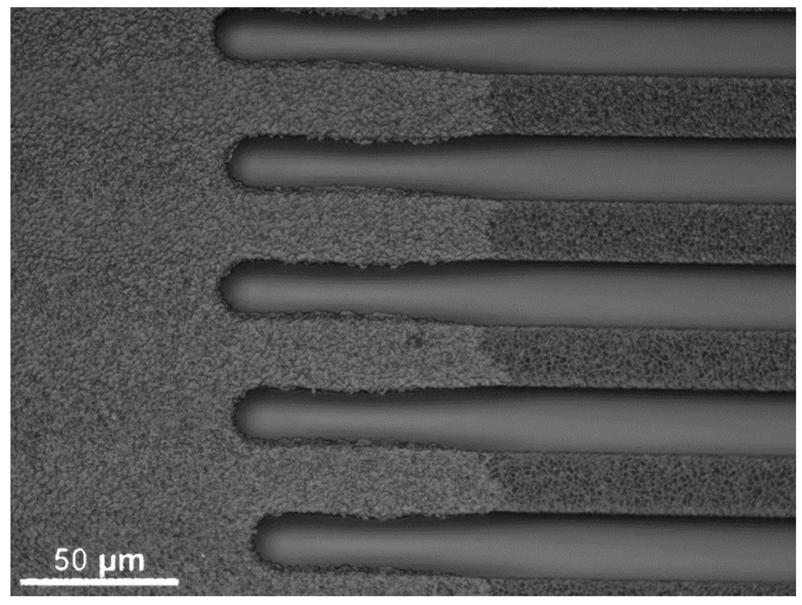
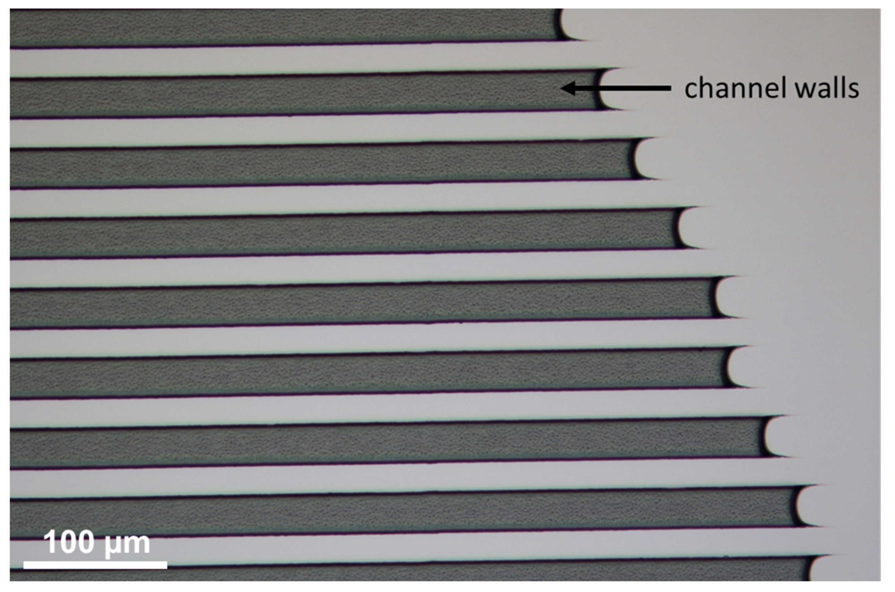
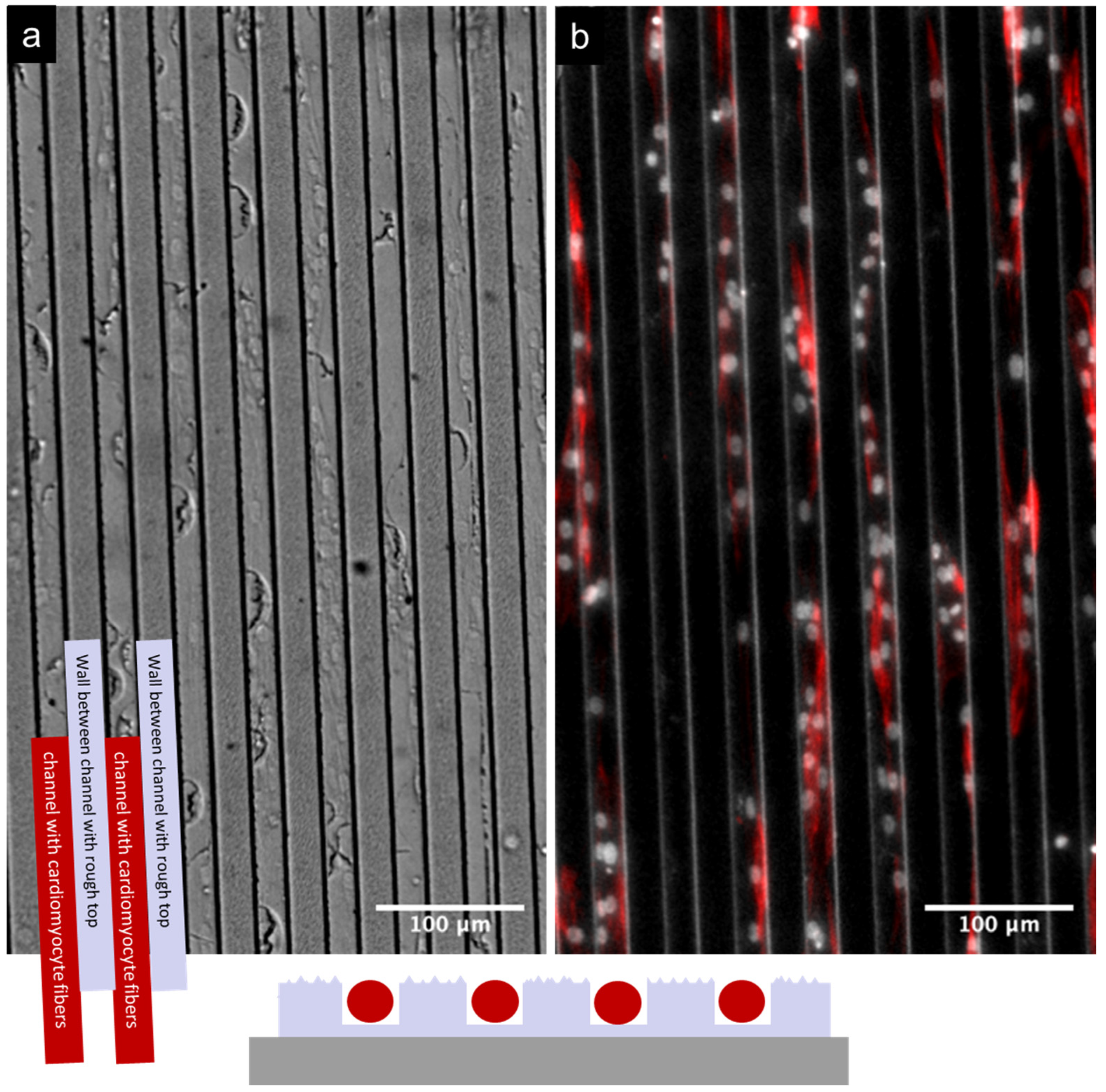
3.1.1. Open and Closed Channels

It is interesting to investigate the behavior of the cells in channels which are closed at one or both ends, and also with different lengths. In the master structure, the channels are closed on both ends (if imprinted in such a way that the roughness is on the top of the walls between the channels). However, the length is fixed to 18 mm. To achieve different channel lengths quickly without the need to make a new master structure each time, we investigated a process which should achieve this with two subsequent imprinting steps. The first imprinting step was a conventional imprint as described above, with a residual layer and made from OrmoComp®. The amount of material and the placement of the PDMS stamp were chosen is such a way as to achieve channels that were closed on one end (Figure 4a) and open on the other end (Figure 4b). For the second imprint, a dedicated PDMS stamp was cut from a larger PDMS stamp, where only the rough and flat area next to the channels was used. Dispensing the OrmoComp® next to the open end of the channel and placing the stamp on top of the end of the first imprint, the imprint material fills part of the existing channels and closes them off, thus creating a channel with a length which can be defined by the placement of the two imprints (see Figure 5). From such a sample, another stamp was replicated to be able to replicate closed channels in a single imprinting step. The end of the channels is then rounded due to the shape of the meniscus of the OrmoComp® when it enters the microchannel, which can also be observed in Figure 6.

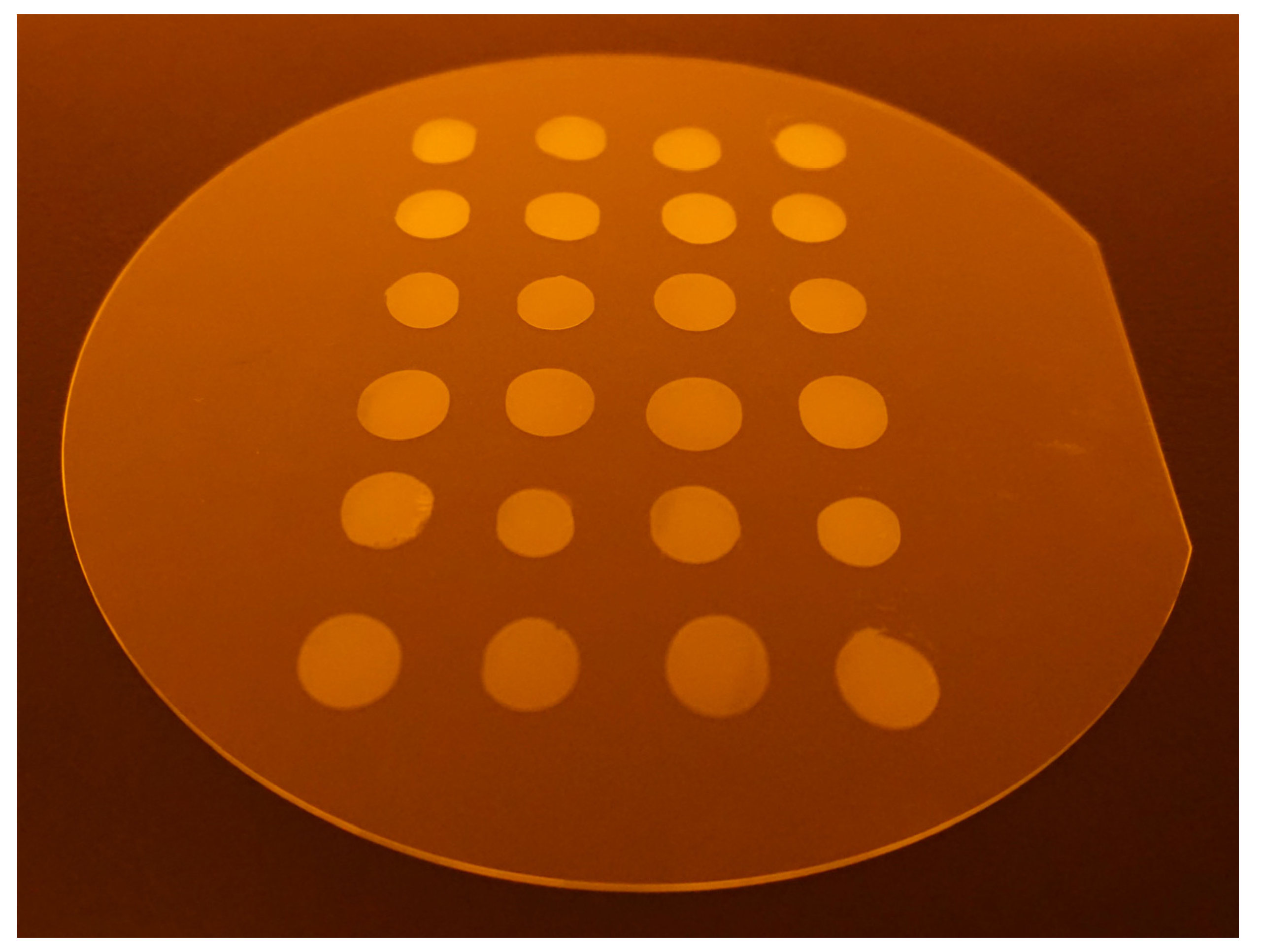
3.1.2. Residual-Layer-Free Samples
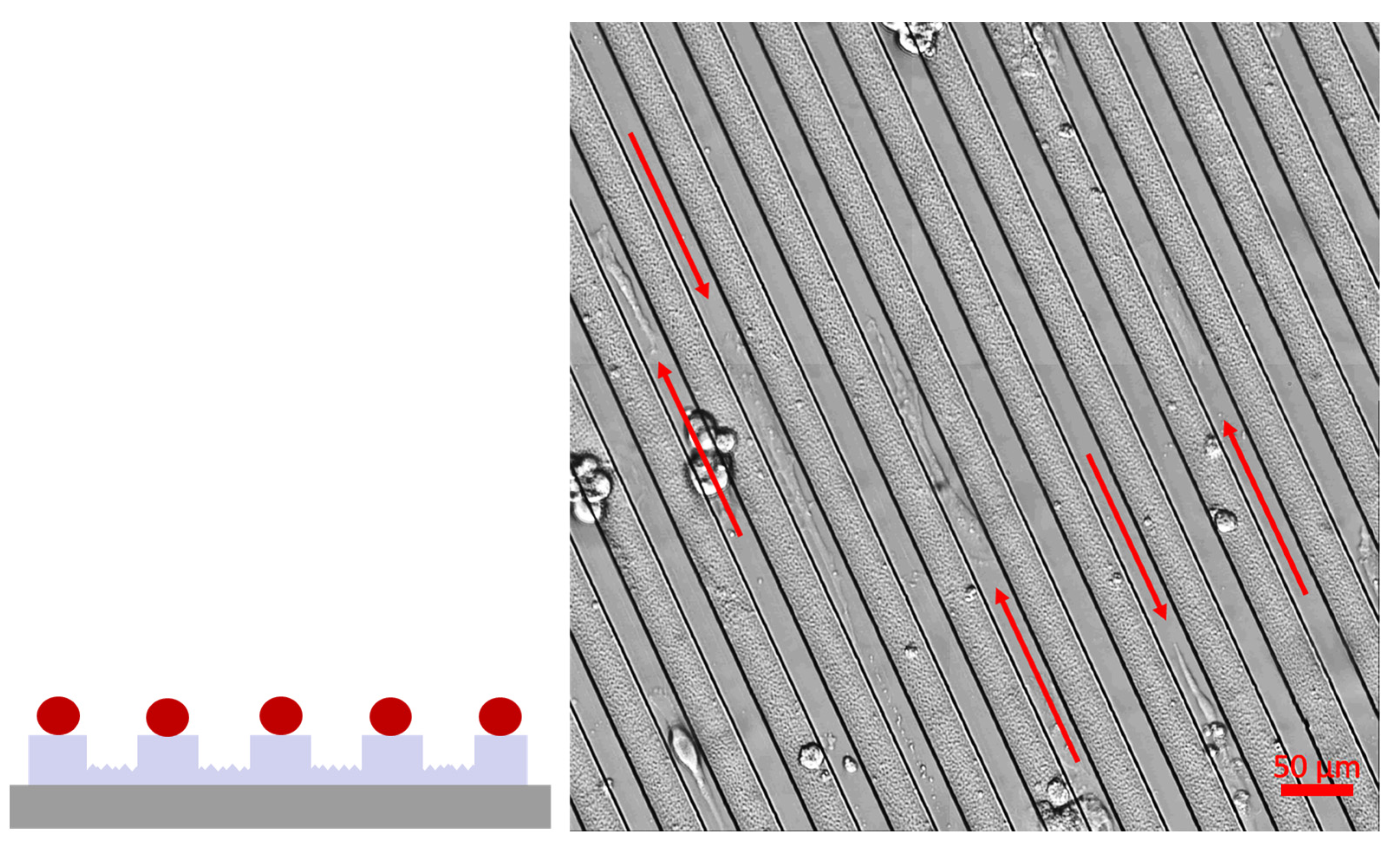
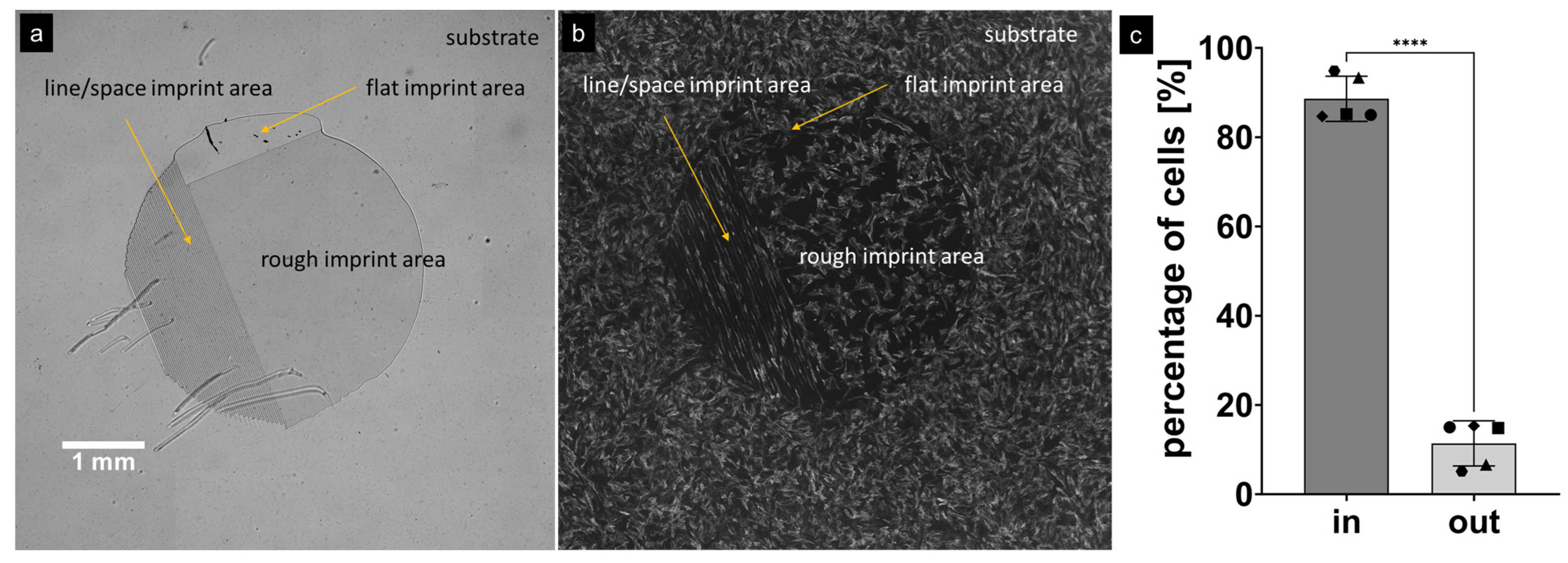
To be able to provide more flexibility in sample design, a residual-layer-free nanoimprinting process was also developed. This should provide samples where the bottom of the channels, i.e. the location, where the cells should be located, will be made from a different material then the channel walls. This process was only established for the structures, where the roughness was on top of the channel walls, since, as discussed below, this structure provided us with the desired cell growth results, with the cells in the bottom of the channels. We used a micromolding in capillaries process (MIMIC) [60]. The stamp was carefully placed on the substrate. Care was taken to make sure that perfect contact between the stamp and the substrate was achieved, which was ensured via careful observation of the contacting area. Air-gaps between stamp and substrate could be identified via visual inspection. OrmoComp® as an imprinting material was placed with a droplet dispenser at the open side of the channels and capillary forces led to the filling of the channels of the stamp, which form the walls between the channels of the final imprint. The sample shown in Figure 6 was prepared on a silicon wafer without any pretreatment of the substrate. Curing was performed as described above. Other residual-layer-free samples were prepared on PVC (with oxygen plasma pretreatment) and on glass (also with oxygen plasma pretreatment).
We used atomic force microscopy (Dimension Edge, Bruker Corporation, Billerica, MA, USA) to assess the roughness on the samples (see Figure 7). An evaluation of the images was performed using Gwyddion [61]. The RMS roughness was evaluated and a value of 174.75 nm ± 5.8 nm was obtained.

3.2. Cell Growth

Cell seeding showed that when the rough pattern was on top of the substrate channel, the cells would adhere almost exclusively to the bottom of the channel barriers. Furthermore, the cardiomyocytes would form long fibers (in the mm range). The formation of the fibers inside the channels is beneficial, since the channel walls provide mechanical guidance and hold the fibers in place when they beat spontaneously. Figure 8 shows the cardiomyocyte fibers forming on top of the channel walls, when the bottom of the channels is rough. Figure 9 shows images of a sample with the roughness on the top of the channel walls. It can be seen that the cells form fibers inside the channels. The cells were stained with troponin T to show cardiomyocyte identity and DAPI (4′,6-diamidino-2-phenylindole) to show the number of cells in each fiber.
Looking at the larger picture and comparing the channel area with the line and space pattern with adjacent areas which are either completely rough (with the same roughness as the top of the channel walls) or completely flat (like the bottom of the channels), it can be observed in Figure 10 that the cells also stay in the rough regions, although with a lower density as compared with the flat region. Figure 10c shows the results of an evaluation of how many cells end up in the grooves and how many end up on top of the walls. It can be seen that approx. 88.6% of the cells are in the channels. Appendix B provides additional data on cell growth without the channels. Appendix C provides additional information on measurements with the cells.

4. Discussion

4.1. Nanoimprinting

We found that choosing nanoimprinting as a fabrication method provided us with the necessary flexibility to prepare different sample layouts from a single master structure. While, generally, nanoimprinting is considered to be a technology that can replicate a given (even very complex) micro/nanopattern with high accuracy, we used a single master design to prepare several different kinds of samples, i.e., roughness on the top or on the bottom, with/without a residual layer, open or closed channels and on different substrates, and keeping the basic micro/nanostructure dimensions constant. In the R2&D setting of our project, this proved to be very helpful and provided us with additional flexibility to quickly provide new sample layouts, while keeping some basic structure parameters constant.
Furthermore, compared to the multistep capillary force lithography described in [62], NIL offers a cost-effective (fast, flexible, high quality) way to fabricate such samples with a process suited to industrial applications [63,64,65,66,67,68,69,70].

4.2. Cell Growth

Looking at the fiber formation in the areas with the channels, it seems that the distance between the two adjacent channels (which is in the range of 10 µm + 30 µm) is small enough to allow the cells to move into the channels, whereas for larger distances the cells cannot move to the areas which are more favorable for them. Interestingly, it can be noted that the cardiomyocytes only form fibers in the channel regions, and in the other areas, the cells are randomly oriented. In these areas, the difference in cell density is slight between the rough large-area region and flat large-area region, while in the channel regions, the roughness induces the cells to move away into the flat area; this does not work that well in the rough large-area regions.
The reason why the rough surface structures on the walls separating the grooves reduce the adhesion of iPSCs-CM is currently not completely clear. In general, an increased surface area might be expected to increase cell adhesion rather than lead to the observed reduction in adhesion. It is, however, tempting to speculate that we deal with a similar effect of rough microstructures, as previously observed for a laser-patterned surface where the density of murine fibroblasts was significantly lower compared to flat surfaces. It was proposed [71,72] that spike-like microstructures form a cell-repellent surface, with the increased hydrophilicity of the surface playing a major role.
To our knowledge, the discovery related to the geometry shown here that rough structures on top of wall structures prevent the adhesion of myocardial cells is new.
Compared to previous attempts to develop nanopatterned surfaces for the culture of iPSCs with much smaller groove diameters (800 nm × 800 nm × 600 nm, groove width × ridge width × ridge height, see [62]), in the present study, we focused on grooves with a width between 10 and 30 µm.

5. Conclusions

We successfully fabricated substrates for the growth of cardiomyocyte fibers with hierarchical micro/nanostructures using UV-based nanoimprint lithography. This method allowed us to be flexible in terms of substrate design and layout, while at the same time they were mass-fabrication-compatible. The nanoimprint material OrmoComp® proved to be suitable for our purposes and allowed for the growth of cardiomyocytes and fiber formation as desired. Manual imprinting as well as roll-to-plate nanoimprinting were used to prepare the substrates. Nanoimprinting has been found to be a well-suited method for research, with the potential to directly upscale the number of samples for testing, which is especially relevant for life science applications like those presented here.
First, encouraging cell growth experiments indicate that cardiomyocytes are evenly distributed across the substrate and preferentially attach themselves to the smooth grooves of the substrate, while not attaching to the rough tops of the walls of the imprinted channels. Detailed investigations regarding cell growth on different types of substrates that were prepared in this study are ongoing. The presented design is a simple and effective approach to induce fiber growth that can be produced by NIL in large quantities for cell culture disposables. Combined with surface electrodes (MEAs), such a geometry will enable the analysis of excitation propagation along individual myocardial fibers.

Author Contributions

Conceptualization, M.M.M., E.G., J.S., S.M., S.H. and H.D.W.; funding acquisition, E.G.; investigation, M.M.M., S.K., A.A.D., M.P., M.J.H., A.M.S., P.T., A.T.-C., B.B., M.A.N., S.P.-L., L.Y., J.S., S.H. and H.D.W.; project administration, M.M.M. and E.G.; supervision, M.M.M. and E.G.; writing—original draft, M.M.M.; writing—review and editing, M.M.M., A.A.D., M.P., M.J.H., P.T., B.B., M.A.N., J.S., S.M., S.H. and H.D.W. All authors have read and agreed to the published version of the manuscript.

Funding

The authors gratefully acknowledge funding from the Austrian Research Promotion Agency FFG via the NEAT project (#871438). This study was also supported by the doctoral program “Molecular drug targets” W1232 of the Austrian Science Fund (FWF).

Data Availability Statement

The data presented in this study are available upon reasonable request from the corresponding author.

Conflicts of Interest

The Institute for Molecular Biotechnology (IMBA) filed a patent application on multi-chamber cardioids, with A.D. and S.M. named as inventors. S.M. is co-founder of HeartBeat.bio AG, an IMBA spin-off company that aims to develop a cardioid drug discovery platform related to the growth of cardiomyocytes. The funders had no role in the design of the study; in the collection, analyses or interpretation of data; in the writing of the manuscript or in the decision to publish the results.

Appendix A. Roll-to-Plate Nanoimprinting

Roll-to-plate nanoimprinting is an interesting variant of UV-NIL. It provides interesting demolding geometry of roller-based processes combined with the flexibility to use foil as well as rigid substrates, in our case, non-transparent substrates if necessary. We used the HoloPrint® uniA6 DT from Stensborg A/S, which is the predecessor of the Desktop R2P NanoImprinter. The HoloPrint® uniA6 DT provides a maximum of 1 Watt/cm (linear LED array) which gives 100 mJ/cm2 at 6 m/min. When using the full width of the machine, the maximum imprinting pressure is around 111 N/cm2, with the minimum at 12 N/cm2.
Figure A1. HoloPrint® uniA6 DT NanoImprinter with mounted printing plate and open hood.
Nanomanufacturing 03 00026 g0a1
Figure A2. Twenty-four imprints made on a 150 mm glass wafer to act as an intermediate large-area master for printing plate fabrication for roll-to-plate nanoimprinting.
Nanomanufacturing 03 00026 g0a2
For the samples in this work, we used a speed setting of ~3 m/min; a UV setting of 2 was used, which corresponds to a curing dose of 80 mJ/cm2. The settings were not optimized for throughput. In the Desktop R2P NanoImprinter, the maximum UV dose is 220 mJ/cm2 at 5 m/min, which is the maximum replication speed. An explanation of how the printing with the Stensborg Desktop R2P NanoImprinter works can be found in [73].

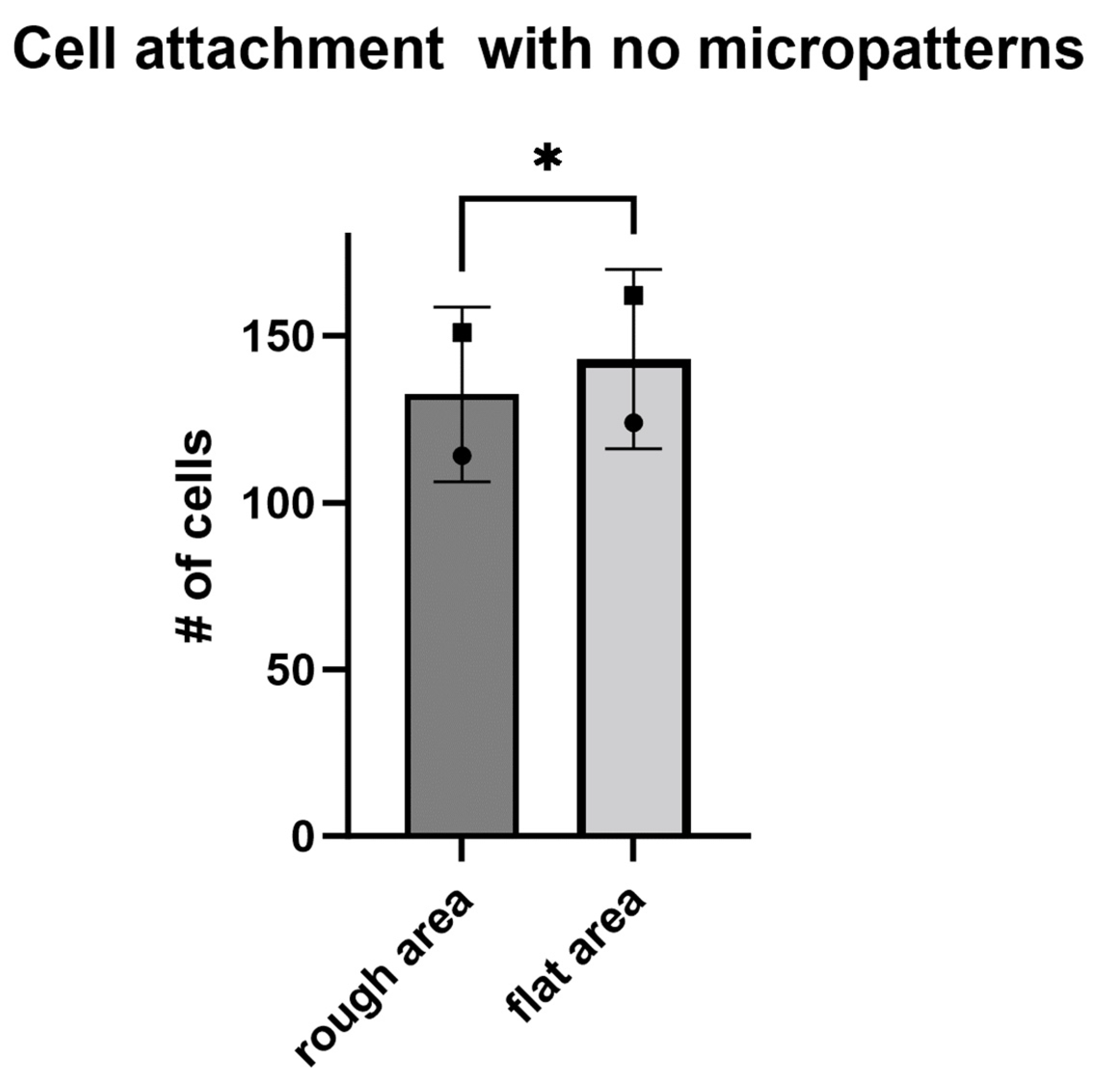
Appendix B. Cell Growth on Substrates without Micro-Channels

If there are no channels present, there seems to be a slight tendency of the cells to be in the flat area as compared to the rough area. Both surfaces were OrmoComp®, imprinted on the same substrate. The measurements for the data in Figure A3 were taken using samples like those shown in Figure 10.
Figure A3. Cell attachment with no micropattern. Symbols represent areas on the same surface. N = 1, n = 2. Paired t-test performed; * p < 0.05.
Nanomanufacturing 03 00026 g0a3

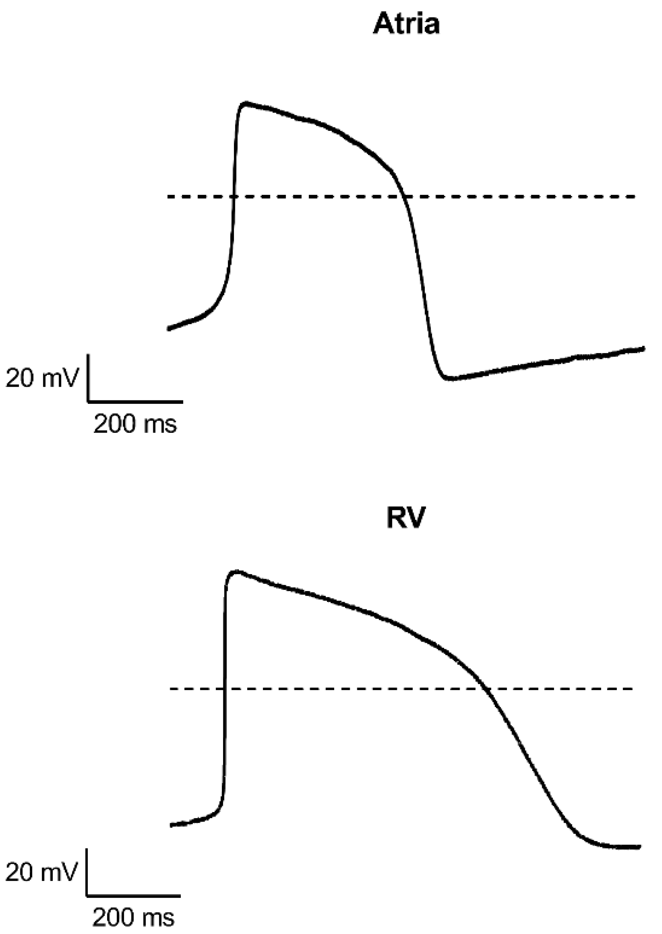
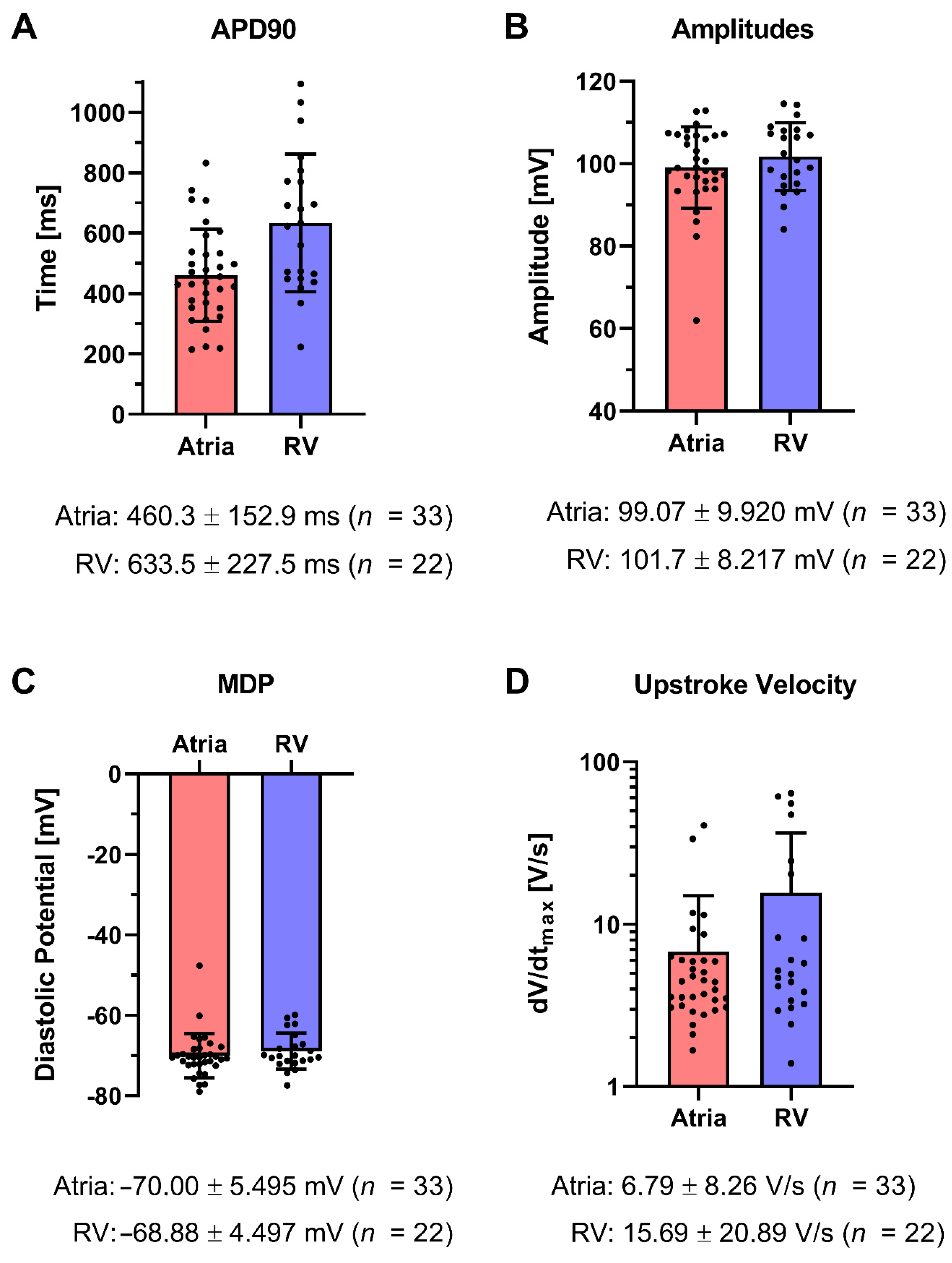
Appendix C. Measurements on Single Cardiomyocytes

The data shown before were obtained at IMBA with cardiomyocytes derived from cardioids, as explained above. At ChanPharm, iPSC-CMs were investigated using standard path clamp technology. Two different sources of induced-pluripotent-stem-cell-derived cardiomyocytes (iPSC-CMs) were tested at ChanPharm for fiber formation:
iCell cardiomyocytes from FUJIFILM Cellular Dynamics, Inc. Madison, Wisconsin, USA [59], that had been previously characterized and that were commercially available.
iPSC-CMs derived from ventricular and atrial cardiac organoids, developed by the member of the consortium IMBA (group of Sasha Mendjan, IMBA).
Before using iPSC-CMs, some basic parameters needed to be established, such as maximum diastolic potential, amplitude of the action potential (AP), upstroke velocity and the length of the action potentials at 90% repolarization (APD90), and beating frequency (BF).
In order to establish these parameters, ChanPharm dissociated the cardioids obtained from the consortium member (IMBA) into single cells that were subsequently characterized by means of standard patch clamp technology. The dissociation procedure is described in [74]. ChanPharm developed and refined a software package for the automatic analysis of the above-mentioned action potential parameters.

Patch Clamp Recordings of Single Cardiomyocytes

The details of the patch clamp recordings can be found in [74]. Spontaneous electrical activity was recorded in the current clamp mode. Analyses were performed using MATLAB (MathWorks, version 2020a). Action potential amplitudes were measured from peak to maximum diastolic potential, and APD values were calculated from action potential peak to the respective percentage of the amplitude’s repolarization. Parameters were individually calculated for 15 to 20 consecutive action potentials per cell and then averaged.
Measuring the spontaneous electrical activity of these cells revealed an adequate but immature phenotype indicated by the low upstroke velocity. AP amplitudes and maximum diastolic potentials showed low variability, hinting at high homogeneity and efficient differentiation of the underlying cell population. The durations of action potentials were longer than in adult human cardiomyocytes (200–450 ms), a feature which is common among many hiPSC-derived cardiomyocyte systems [75,76,77].
Taken together, this initial electrophysiological characterization of cardioids further reinforces their strength to be used in a suitable in vitro system of the developing human heart and justifies the use of such cells for our experiments.
Figure A4. Representative patch clamp action potential recordings from single cardiomyocytes of atria (top) and right ventricular (bottom) cardioids. Dashed line indicates 0 mV.
Nanomanufacturing 03 00026 g0a4
Figure A5. Action potential parameters of cardioid cardiomyocytes. (A) APD90, (B) amplitude, (C) maximum diastolic potential, and (D) upstroke velocity values calculated from action potentials elicited spontaneously by atrial (red) and right ventricular (blue) cardiomyocytes. Data displayed as average and standard deviation under each graph.
Nanomanufacturing 03 00026 g0a5

References

  1. Ghane-Motlagh, B.; Sawan, M. A Review of Microelectrode Array Technologies: Design and Implementation Challenges. In Proceedings of the 2013 2nd International Conference on Advances in Biomedical Engineering, Tripoli, Lebanon, 11–13 September 2013; IEEE: Piscataway, NJ, USA, 2013; pp. 38–41. [Google Scholar]
  2. Chen, P.; Zhang, W.; Zhou, J.; Wang, P.; Xiao, L.; Yang, M. Development of Planar Patch Clamp Technology and Its Application in the Analysis of Cellular Electrophysiology. Prog. Nat. Sci. 2009, 19, 153–160. [Google Scholar] [CrossRef]
  3. Bébarová, M. Advances in Patch Clamp Technique: Towards Higher Quality and Quantity. Gen. Physiol. Biophys. 2012, 31, 131–140. [Google Scholar] [CrossRef] [PubMed]
  4. Heist, E.K.; Ruskin, J.N. Drug-Induced Arrhythmia. Circulation 2010, 122, 1426–1435. [Google Scholar] [CrossRef] [PubMed]
  5. Tisdale, J.E.; Chung, M.K.; Campbell, K.B.; Hammadah, M.; Joglar, J.A.; Leclerc, J.; Rajagopalan, B.; On behalf of the American Heart Association Clinical Pharmacology Committee of the Council on Clinical Cardiology and Council on Cardiovascular and Stroke Nursing. Drug-Induced Arrhythmias: A Scientific Statement From the American Heart Association. Circulation 2020, 142, e214–e233. [Google Scholar] [CrossRef]
  6. Hofbauer, P.; Jahnel, S.M.; Papai, N.; Giesshammer, M.; Deyett, A.; Schmidt, C.; Penc, M.; Tavernini, K.; Grdseloff, N.; Meledeth, C.; et al. Cardioids Reveal Self-Organizing Principles of Human Cardiogenesis. Cell 2021, 184, 3299–3317.e22. [Google Scholar] [CrossRef]
  7. Thomson, J.A.; Itskovitz-Eldor, J.; Shapiro, S.S.; Waknitz, M.A.; Swiergiel, J.J.; Marshall, V.S.; Jones, J.M. Embryonic Stem Cell Lines Derived from Human Blastocysts. Science 1998, 282, 1145–1147. [Google Scholar] [CrossRef]
  8. Kehat, I.; Kenyagin-Karsenti, D.; Snir, M.; Segev, H.; Amit, M.; Gepstein, A.; Livne, E.; Binah, O.; Itskovitz-Eldor, J.; Gepstein, L. Human Embryonic Stem Cells Can Differentiate into Myocytes with Structural and Functional Properties of Cardiomyocytes. J. Clin. Investig. 2001, 108, 407–414. [Google Scholar] [CrossRef]
  9. Takahashi, K.; Tanabe, K.; Ohnuki, M.; Narita, M.; Ichisaka, T.; Tomoda, K.; Yamanaka, S. Induction of Pluripotent Stem Cells from Adult Human Fibroblasts by Defined Factors. Cell 2007, 131, 861–872. [Google Scholar] [CrossRef]
  10. Burridge, P.W.; Matsa, E.; Shukla, P.; Lin, Z.C.; Churko, J.M.; Ebert, A.D.; Lan, F.; Diecke, S.; Huber, B.; Mordwinkin, N.M.; et al. Chemically Defined Generation of Human Cardiomyocytes. Nat. Methods 2014, 11, 855–860. [Google Scholar] [CrossRef]
  11. Curtis, A.S.G.; Gadegaard, N.; Dalby, M.J.; Riehle, M.O.; Wilkinson, C.D.W.; Aitchison, G. Cells React to Nanoscale Order and Symmetry in Their Surroundings. IEEE Trans. Nanobiosci. 2004, 3, 61–65. [Google Scholar] [CrossRef]
  12. Dalby, M.J.; Gadegaard, N.; Oreffo, R.O.C. Harnessing Nanotopography and Integrin–Matrix Interactions to Influence Stem Cell Fate. Nat. Mater. 2014, 13, 558–569. [Google Scholar] [CrossRef] [PubMed]
  13. Carthew, J.; Abdelmaksoud, H.H.; Hodgson-Garms, M.; Aslanoglou, S.; Ghavamian, S.; Elnathan, R.; Spatz, J.P.; Brugger, J.; Thissen, H.; Voelcker, N.H.; et al. Precision Surface Microtopography Regulates Cell Fate via Changes to Actomyosin Contractility and Nuclear Architecture. Adv. Sci. 2021, 8, 2003186. [Google Scholar] [CrossRef] [PubMed]
  14. Han, E.D.; Kim, B.H.; Seo, Y.H. Anti-Cell Adhesion Characteristics of Nanotextured Surface for Implantable Biomedical Device. Int. J. Precis. Eng. Manuf. 2017, 18, 239–244. [Google Scholar] [CrossRef]
  15. Mobini, S.; Kuliasha, C.A.; Siders, Z.A.; Bohmann, N.A.; Jamal, S.-M.; Judy, J.W.; Schmidt, C.E.; Brennan, A.B. Microtopographical Patterns Promote Different Responses in Fibroblasts and Schwann Cells: A Possible Feature for Neural Implants. J. Biomed. Mater. Res. Part A 2021, 109, 64–76. [Google Scholar] [CrossRef]
  16. Batalov, I. Engineering Aligned Human Cardiac Muscle Using Developmentally Inspired Fibronectin Micropatterns. Sci. Rep. 2021, 11, 11502. [Google Scholar] [CrossRef]
  17. Zhang, F.; Low, H.Y. Ordered Three-Dimensional Hierarchical Nanostructures by Nanoimprint Lithography. Nanotechnology 2006, 17, 1884–1890. [Google Scholar] [CrossRef]
  18. Durret, J.; Szkutnik, P.-D.; Frolet, N.; Labau, S.; Gourgon, C. Superhydrophobic Polymeric Films with Hierarchical Structures Produced by Nanoimprint (NIL) and Plasma Roughening. Appl. Surf. Sci. 2018, 445, 97–106. [Google Scholar] [CrossRef]
  19. Choo, S.; Choi, H.-J.; Lee, H. Replication of Rose-Petal Surface Structure Using UV-Nanoimprint Lithography. Mater. Lett. 2014, 121, 170–173. [Google Scholar] [CrossRef]
  20. Latthe, S.; Terashima, C.; Nakata, K.; Fujishima, A. Superhydrophobic Surfaces Developed by Mimicking Hierarchical Surface Morphology of Lotus Leaf. Molecules 2014, 19, 4256–4283. [Google Scholar] [CrossRef]
  21. Schift, H. Nanoimprint Lithography: An Old Story in Modern Times? A Review. J. Vac. Sci. Technol. B Microelectron. Nanometer Struct. 2008, 26, 458. [Google Scholar] [CrossRef]
  22. Chou, S.Y. Nanoimprint Lithography. J. Vac. Sci. Technol. B 1996, 14, 4129. [Google Scholar] [CrossRef]
  23. Haisma, J. Mold-Assisted Nanolithography: A Process for Reliable Pattern Replication. J. Vac. Sci. Technol. B Microelectron. Nanometer Struct. 1996, 14, 4124. [Google Scholar] [CrossRef]
  24. Mühlberger, M. Nanoimprint Lithography Technology and Applications; Nanomaterials; MDPI: Basel, Switzerland, 2022; ISBN 978-3-0365-4482-3. [Google Scholar]
  25. Xia, Y.; Whitesides, G.M. Soft Lithography. Annu. Rev. Mater. Sci. 1998, 28, 153–184. [Google Scholar] [CrossRef]
  26. Muehlberger, M. Nanoimprinting of Biomimetic Nanostructures. Nanomanufacturing 2022, 2, 17–40. [Google Scholar] [CrossRef]
  27. Muehlberger, M.; Ruttloff, S.; Nees, D.; Moharana, A.; Belegratis, M.R.; Taus, P.; Kopp, S.; Wanzenboeck, H.D.; Prinz, A.; Fechtig, D. Nanoimprint Replication of Biomimetic, Multilevel Undercut Nanostructures. Nanomaterials 2021, 11, 1051. [Google Scholar] [CrossRef] [PubMed]
  28. Pribyl, M.; Taus, P.; Prado-López, S.; Dozio, S.M.; Schrenk, W.; Haslinger, M.J.; Kopp, S.; Mühlberger, M.; Wanzenboeck, H.D. Dense High Aspect Ratio Nanostructures for Cell Chip Applications—Fabrication, Replication, and Cell Interactions. Micro Nano Eng. 2022, 15, 100121. [Google Scholar] [CrossRef]
  29. Wanzenboeck, H.D.; Waid, S.; Bertagnolli, E.; Muehlberger, M.; Bergmair, I.; Schoeftner, R. Nanoimprint Lithography Stamp Modification Utilizing Focused Ion Beams. J. Vac. Sci. Technol. B 2009, 27, 7. [Google Scholar] [CrossRef]
  30. Schizas, C.; Karalekas, D. Mechanical Characteristics of an Ormocomp® Biocompatible Hybrid Photopolymer. J. Mech. Behav. Biomed. Mater. 2011, 4, 99–106. [Google Scholar] [CrossRef]
  31. Stewart, M.D.; Willson, C.G. Imprint Materials for Nanoscale Devices. Mrs. Bull. 2005, 30, 947. [Google Scholar] [CrossRef]
  32. Vig, A.L.; Mäkelä, T.; Majander, P.; Lambertini, V.; Ahopelto, J.; Kristensen, A. Roll-to-Roll Fabricated Lab-on-a-Chip Devices. J. Micromech. Microeng. 2011, 21, 035006. [Google Scholar] [CrossRef]
  33. Smolka, M.; Haase, A.; Palfinger, U.; Nees, D.; Kuna, L.; Hesse, J.; Stadlober, B.; Geidel, S.; Nestler, J.; Ladenhauf, N.; et al. Roll-to-Roll Pilot Line for Large-Scale Manufacturing of Microfluidic Devices. In Proceedings of the Single-use Technologies II: Bridging Polymer Science to Biotechnology Applications, Tomar, Portugal, 7–10 May 2017; p. 23. [Google Scholar]
  34. Smolka, M.; Ruttloff, S.; Nees, D.; Prietl, C.; Satzinger, V.; Lamprecht, B.; Hütter, P.; Hesse, J.; Kokkinis, G.; Kriechhammer, G.; et al. High Throughput Roll-to-Roll Production of Microfluidic Chips. Proceedings 2018, 2, 1054. [Google Scholar] [CrossRef]
  35. Nguyen, V.T.H.; Jensen, F.; Hübner, J.; Leussink, P.; Jansen, H. On the Formation of Black Silicon in SF6-O2 Plasma: The Clear, Oxidize, Remove, and Etch (CORE) Sequence and Black Silicon on Demand. J. Vac. Sci. Technol. A 2020, 38, 043004. [Google Scholar] [CrossRef]
  36. Zhu, F.; Zhang, X.; Zhang, H. Formation Mechanism of Multi-Functional Black Silicon Based on Optimized Deep Reactive Ion Etching Technique with SF6/C4F8. Sci. China Technol. Sci. 2015, 58, 381–389. [Google Scholar] [CrossRef]
  37. Silvestre, C.M.; Nguyen, V.; Jansen, H.; Hansen, O. Deep Reactive Ion Etching of ‘Grass-Free’ Widely-Spaced Periodic 2D Arrays, Using Sacrificial Structures. Microelectron. Eng. 2020, 223, 111228. [Google Scholar] [CrossRef]
  38. Kroll, M.; Käsebier, T.; Otto, M.; Salzer, R.; Wehrspohn, R.; Kley, E.-B.; Tünnermann, A.; Pertsch, T. Optical Modeling of Needle like Silicon Surfaces Produced by an ICP-RIE Process. In Proceedings of the fo SPIE Photonics Europe, Brussels, Belgium, 12–16 April 2010; Wehrspohn, R.B., Gombert, A., Eds.; SPIE: Brussels, Belgium, 2010; p. 772505. [Google Scholar]
  39. Jansen, H.; de Boer, M.; Legtenberg, R.; Elwenspoek, M. The Black Silicon Method: A Universal Method for Determining the Parameter Setting of a Fluorine-Based Reactive Ion Etcher in Deep Silicon Trench Etching with Profile Control. J. Micromech. Microeng. 1995, 5, 115. [Google Scholar] [CrossRef]
  40. Holland-Moritz, H.; Ilinov, A.; Djurabekova, F.; Nordlund, K.; Ronning, C. Sputtering and Redeposition of Ion Irradiated Au Nanoparticle Arrays: Direct Comparison of Simulations to Experiments. New J. Phys. 2017, 19, 013023. [Google Scholar] [CrossRef]
  41. Lugstein, A.; Basnar, B.; Smoliner, J.; Bertagnolli, E. FIB Processing of Silicon in the Nanoscale Regime. Appl. Phys. A Mater. Sci. Process. 2003, 76, 545–548. [Google Scholar] [CrossRef]
  42. Lindsey, S.; Waid, S.; Hobler, G.; Wanzenböck, H.D.; Bertagnolli, E. Inverse Modeling of FIB Milling by Dose Profile Optimization. Nucl. Instrum. Methods Phys. Res. Sect. B Beam Interact. Mater. At. 2014, 341, 77–83. [Google Scholar] [CrossRef]
  43. Kim, H.-B.; Hobler, G.; Steiger, A.; Lugstein, A.; Bertagnolli, E. Full Three-Dimensional Simulation of Focused Ion Beam Micro/Nanofabrication. Nanotechnology 2007, 18, 245303. [Google Scholar] [CrossRef]
  44. Rumyantsev, A.V.; Borgardt, N.I.; Volkov, R.L. Simulation of Redeposited Silicon Sputtering under Focused Ion Beam Irradiation. J. Surf. Investig. 2018, 12, 607–612. [Google Scholar] [CrossRef]
  45. Gassend, B.L.P.; Velasquez-Garcia, L.F.; Akinwande, A.I. Design and Fabrication of DRIE-Patterned Complex Needlelike Silicon Structures. J. Microelectromech. Syst. 2010, 19, 589–598. [Google Scholar] [CrossRef]
  46. Grigoropoulos, S. Highly Anisotropic Silicon Reactive Ion Etching for Nanofabrication Using Mixtures OfSF[Sub 6]/CHF[Sub 3] Gases. J. Vac. Sci. Technol. B 1997, 15, 640. [Google Scholar] [CrossRef]
  47. Franz, G.; Oberhausen, W.; Meyer, R.; Amann, M.-C. Residual-Free Reactive Ion Etching of Gold Layers. AIP Adv. 2018, 8, 075026. [Google Scholar] [CrossRef]
  48. Micro Resist Technology OrmoComp®—Micro Resist Technology. Available online: https://www.microresist.de/produkt/ormocomp/ (accessed on 21 February 2023).
  49. Kidwell, D.A.; Lee, W.-K.; Perkins, K.; Gilpin, K.M.; O’Shaughnessy, T.J.; Robinson, J.T.; Sheehan, P.E.; Mulvaney, S.P. Chemistries for Making Additive Nanolithography in OrmoComp Permissive for Cell Adhesion and Growth. ACS Appl. Mater. Interfaces 2019, 11, 19793–19798. [Google Scholar] [CrossRef]
  50. Stensborg Welcome to Stensborg A/S. Available online: https://www.stensborg.com/ (accessed on 15 December 2022).
  51. Zhuang, G.; Kutter, J.P. Anti-Stiction Coating of PDMS Moulds for Rapid Microchannel Fabrication by Double Replica Moulding. J. Micromech. Microeng. 2011, 21, 105020. [Google Scholar] [CrossRef]
  52. Mühlberger, M.; Bergmair, I.; Klukowska, A.; Kolander, A.; Leichtfried, H.; Platzgummer, E.; Loeschner, H.; Ebm, C.h.; Grützner, G.; Schöftner, R. UV-NIL with Working Stamps Made from Ormostamp. Microelectron. Eng. 2009, 86, 691–693. [Google Scholar] [CrossRef]
  53. PROFACTOR BGL-GZ-83, Profactor: Steyr, Austria, 2022.
  54. Deckgläser, Rund. Available online: https://at.vwr.com/store/product/11973345/deckglaser-rund (accessed on 9 December 2022).
  55. Diener Elektronik Nano Plasmaanlage Diener Elektronik. Available online: https://www.plasma.com/produkte/plasmaanlagen/niederdruckplasma-anlagen/nano/ (accessed on 29 November 2017).
  56. PROFACTOR HMNP-12|Coatings|Profactor. Available online: https://www.profactor.at/en/solutions/nil-coatings/#HMNP-12 (accessed on 3 October 2023).
  57. Stensborg Desktop R2P NanoImprinter. Available online: https://www.stensborg.com/desktop-r2p-nanoimprinter (accessed on 15 December 2022).
  58. Lee, H.; Im, J.S.; Choi, D.B.; An, J.; Kim, S.-B.; Yeon, S.; Yoon, S.; Woo, D.-H. Three-Dimensional Cardiac Organoid Formation Accelerates the Functional Maturation of Human Induced Pluripotent Stem Cell-Derived Cardiomyocytes. Organoid 2022, 2, e14. [Google Scholar] [CrossRef]
  59. ICell Cardiomyocytes|FujiFilm Cellular Dynamics, Inc. Available online: https://www.fujifilmcdi.com/products/cardiac-cells/icell-cardiomyocytes (accessed on 12 December 2022).
  60. Kim, E.; Xia, Y.; Whitesides, G.M. Micromolding in Capillaries: Applications in Materials Science. J. Am. Chem. Soc. 1996, 118, 5722–5731. [Google Scholar] [CrossRef]
  61. Nečas, D.; Klapetek, P. Gwyddion: An Open-Source Software for SPM Data Analysis. Open Phys. 2012, 10, 181–188. [Google Scholar] [CrossRef]
  62. Smith, A.S.T.; Choi, E.; Gray, K.; Macadangdang, J.; Ahn, E.H.; Clark, E.C.; Laflamme, M.A.; Wu, J.C.; Murry, C.E.; Tung, L.; et al. NanoMEA: A Tool for High-Throughput, Electrophysiological Phenotyping of Patterned Excitable Cells. Nano Lett. 2020, 20, 1561–1570. [Google Scholar] [CrossRef]
  63. Verschuuren, M.A.; Megens, M.; Ni, Y.; van Sprang, H.; Polman, A. Large Area Nanoimprint by Substrate Conformal Imprint Lithography (SCIL). Adv. Opt. Technol. 2017, 6, 243–264. [Google Scholar] [CrossRef]
  64. Mohapatra, S.; Kumari, S.; Moirangthem, R.S. Fabrication of a Cost-Effective Polymer Nanograting as a Disposable Plasmonic Biosensor Using Nanoimprint Lithography. Mater. Res. Express 2017, 4, 076202. [Google Scholar] [CrossRef]
  65. Resnick, D.J.; Choi, J. A Review of Nanoimprint Lithography for High-Volume Semiconductor Device Manufacturing. Adv. Opt. Technol. 2017, 6, 229–241. [Google Scholar] [CrossRef]
  66. Buhl, J.; Yoo, D.; Köpke, M.; Gerken, M. Two-Dimensional Nanograting Fabrication by Multistep Nanoimprint Lithography and Ion Beam Etching. Nanomanufacturing 2021, 1, 39–48. [Google Scholar] [CrossRef]
  67. Oh, J.; Hoffman, J.B.; Hong, S.; Jo, K.D.; Román-Kustas, J.; Reed, J.H.; Dana, C.E.; Cropek, D.M.; Alleyne, M.; Miljkovic, N. Dissolvable Template Nanoimprint Lithography: A Facile and Versatile Nanoscale Replication Technique. Nano Lett. 2020, 20, 6989–6997. [Google Scholar] [CrossRef] [PubMed]
  68. Pandey, A.; Tzadka, S.; Yehuda, D.; Schvartzman, M. Soft Thermal Nanoimprint with a 10 Nm Feature Size. Soft Matter 2019, 15, 2897–2904. [Google Scholar] [CrossRef]
  69. Cox, L.M.; Martinez, A.M.; Blevins, A.K.; Sowan, N.; Ding, Y.; Bowman, C.N. Nanoimprint Lithography: Emergent Materials and Methods of Actuation. Nano Today 2020, 31, 100838. [Google Scholar] [CrossRef]
  70. Nowduri, B.; Schulte, S.; Decker, D.; Schäfer, K.-H.; Saumer, M. Biomimetic Nanostructures Fabricated by Nanoimprint Lithography for Improved Cell-Coupling. Adv. Funct. Mater. 2020, 30, 2004227. [Google Scholar] [CrossRef]
  71. Heitz, J.; Plamadeala, C.; Muck, M.; Armbruster, O.; Baumgartner, W.; Weth, A.; Steinwender, C.; Blessberger, H.; Kellermair, J.; Kirner, S.V.; et al. Femtosecond Laser-Induced Microstructures on Ti Substrates for Reduced Cell Adhesion. Appl. Phys. A 2017, 123, 734. [Google Scholar] [CrossRef]
  72. Fosodeder, P.; Baumgartner, W.; Steinwender, C.; Hassel, A.W.; Florian, C.; Bonse, J.; Heitz, J. Repellent Rings at Titanium Cylinders against Overgrowth by Fibroblasts. Adv. Opt. Technol. 2020, 9, 113–120. [Google Scholar] [CrossRef]
  73. Stensborg Soft Lithography with Desktop R2P NanoImprinter. Available online: https://www.youtube.com/watch?v=3GSQHuDmbHQ (accessed on 17 August 2023).
  74. Schmidt, C.; Deyett, A.; Ilmer, T.; Caballero, A.T.; Haendeler, S.; Pimpale, L.; Netzer, M.A.; Ginistrelli, L.C.; Cirigliano, M.; Mancheno, E.J.; et al. Multi-Chamber Cardioids Unravel Human Heart Development and Cardiac Defects. Biorxiv 2022. [Google Scholar] [CrossRef]
  75. Li, G.-R.; Feng, J.; Yue, L.; Carrier, M. Transmural Heterogeneity of Action Potentials AndI To1 in Myocytes Isolated from the Human Right Ventricle. Am. J. Physiol. Heart Circ. Physiol. 1998, 275, H369–H377. [Google Scholar] [CrossRef] [PubMed]
  76. Workman, A.J.; Kane, K.A.; Rankin, A.C. The Contribution of Ionic Currents to Changes in Refractoriness of Human Atrial Myocytes Associated with Chronic Atrial Fibrillation. Cardiovasc. Res. 2001, 52, 226–235. [Google Scholar] [CrossRef] [PubMed]
  77. Ma, J.; Guo, L.; Fiene, S.J.; Anson, B.D.; Thomson, J.A.; Kamp, T.J.; Kolaja, K.L.; Swanson, B.J.; January, C.T. High Purity Human-Induced Pluripotent Stem Cell-Derived Cardiomyocytes: Electrophysiological Properties of Action Potentials and Ionic Currents. Am. J. Physiol. Heart Circ. Physiol. 2011, 301, H2006–H2017. [Google Scholar] [CrossRef]
Figure 1. SEM images of different master structures. Spacing from left to right: (a,d): 10 µm, (b,e): 20 µm, (c,f): 30 µm. The scale bar is 20 µm in all images and the same for (ac) and (df), respectively.
Nanomanufacturing 03 00026 g001
Figure 2. (a): Photograph of a master, prepared on a glass holder with a PDMS frame for PDMS casting. (b): Photograph of first- and second-stamp copies.
Nanomanufacturing 03 00026 g002
Figure 3. Photograph of a 24-well plate, with the top 2 rows fitted with nanoimprinted substrates.
Nanomanufacturing 03 00026 g003
Figure 4. (a): End of the channels as defined on the master. (b): Open end of the channels in an imprint with residual layer.
Nanomanufacturing 03 00026 g004
Figure 5. Optical micrograph of the closed end of the channels which was fabricated via a second imprinting step.
Nanomanufacturing 03 00026 g005
Figure 6. Optical micrograph of the end of open channels imprinted without residual layer on a glass substrate. The darker areas are the channel walls with roughness on top, and the light gray area is the glass substrate. The shape of the meniscus of the OrmoComp® while flowing into the wall cavities of the stamp can be seen at the end of the walls.
Nanomanufacturing 03 00026 g006
Figure 7. AFM image of the rough area on the imprinted structure.
Nanomanufacturing 03 00026 g007
Figure 8. (Right): Sample with the roughness on the bottom of the channels. The cells tend to grow on top of the flat walls; cardiomyocyte fibers indicated by the arrows. (Left): Side view sketch of the cardiomyocyte fiber arrangement on the sample.
Nanomanufacturing 03 00026 g008
Figure 9. Sample with the roughness on the top of the channel walls. The cells tend to grow inside the channels between the walls. (a): Optical micrograph with some of the wall and channel areas highlighted. (b): Optical micrograph with troponin (red) marking cardiomyocytes and DAPI (gray) marking cell nuclei used for staining. The scale bar is 100 µm for both images.
Nanomanufacturing 03 00026 g009
Figure 10. (a): Overview of optical micrograph showing a small spot of patterned OrmoComp®. Different types of surface are present: the line/space area with the channels for fiber formation, a larger area with just the roughness and a smaller area of just flat OrmoComp®. (b): Cells marked with pan-cardiomyocyte marker (troponin T) seeded on the surface are shown on the left. It can be seen that the fibers are only formed in the channel area. In the channel area, the roughness repels the cells and they only grow in the flat areas; roughness on a larger area does not repel the cells. (c): Cell attachment in the grooves. For the pattern shown in this paper, approximately 88.6% ± 4.5% of all cells attach to the bottom of the grooves, i.e., stay in the channels. Symbols represent data from the same surface. N = 3 (biological replicate cells from the same batch of cardioids) and n = 5 (number of surfaces that were quantified). Paired t-test was performed; **** p < 0.0001.
Nanomanufacturing 03 00026 g010
Disclaimer/Publisher’s Note: The statements, opinions and data contained in all publications are solely those of the individual author(s) and contributor(s) and not of MDPI and/or the editor(s). MDPI and/or the editor(s) disclaim responsibility for any injury to people or property resulting from any ideas, methods, instructions or products referred to in the content.

