Article

Geotechnical Issues in Decommissioning Surface Lignite Mines—The Case of Amyntaion Mine in Greece

by
Michael Kavvadas
1,
Christos Roumpos
2,*,
Aikaterini Servou
2 and
Nikolaos Paraskevis
2
1
Professor Emeritus, School of Civil Engineering, National Technical University of Athens (NTUA), 157 80 Zografou, Greece
2
Mining Engineering and Closure Planning Department Public Power Corporation of Greece, 104 32 Athens, Greece
*
Author to whom correspondence should be addressed.
Mining 2022, 2(2), 278-296; https://doi.org/10.3390/mining2020015
Submission received: 14 March 2022 / Revised: 24 April 2022 / Accepted: 26 April 2022 / Published: 29 April 2022

Abstract

:
Recent changes in the fossil-fuel energy sector require coal mining industries to plan for the future, including developing procedures for decommissioning and closure associated with mines. In surface coal mining, the geotechnical issues of decommissioning include the long-term stability of the pit slopes, particularly as the pit is gradually filled with water. This paper investigates such slope stability issues, with emphasis on the conditions prevailing in the Amyntaion surface lignite mine, in Western Macedonia, Greece. Analytical and numerical methods have been developed and used to estimate the temporal evolution of the overall safety factor, as the water level in the pit rises, creating a lake. It is shown that until the water level in the lake reaches a critical depth of approximately 15–35% of the final equilibrium condition, the safety factor against the overall slope instability decreases slightly (by about 3% in the case study, and up to 5–10% in other conditions) compared to its value at the end of exploitation. At higher lake levels, the safety factor increases significantly, as the beneficial effect of the lake water pressure acting on the slope overcomes the adverse effect of pore water pressure rise inside the slope. In typical mines, the critical water depth is achieved within a few years, since the surface area of the pit is smaller at deeper levels; thus, more favorable slope stability conditions are usually reinstated a few years after mine closure, while the small reduction in safety during the initial stages after closure is inconsequential. The paper investigates the parameters influencing the magnitude of the small reduction in the short-term safety factor and produces normalized graphs of the evolution of the safety factor as the lake water level rises. The results of the analyses can be used in preliminary closure studies of surface coal mines.

1. Introduction

With international policies for the transition to a decarbonized economy, increasing greenhouse gas (GHG) emission costs, the use of lignite (brown coal), and the local fossil fuel for electricity production in Greece becomes gradually uneconomical. As a result, large-scale exploitation of surface lignite mines in Greece is gradually reduced and plans are being developed for decommissioning several lignite mines in an environmentally friendly way. As earth materials for backfilling the deep mine pits (several kilometers in size and up to 200 m deep) are not available by opening new mines (and using their spoils for filling older mines), the present mine pits will be gradually filled with water from precipitation and groundwater seepage, creating artificial lakes and new aquatic ecosystems. However, either in the case of filling the under-closure mining area with materials or with water, the slope stability investigations are considered of primary importance [1]. It is thus important to investigate the long-term environmental effects of these lakes, including the stability of the mine slopes, as the water level in the pit lakes rises gradually.
Mine closure activities include a set of procedures from concept planning to a detailed closure plan, post-closure monitoring activities, and post-closure land re-use [2,3]. These activities also include the determination of end uses, which depend on the water quality, slope stability, and safety issues. Possible end-uses could be for wildlife (flora and fauna), recreation uses (swimming, hunting, diving, fisheries), or primary production (agricultural areas, irrigated crops). Therefore, a successful mine closure should be designed with a transdisciplinary approach combining geological, hydrogeological, hydrological, geochemical, and ecological aspects [4]. The creation of pit lakes constitutes one of the most environmentally friendly and sustainable post-closure land uses, especially in areas favored by ground morphology and a high groundwater table. However, if not properly designed, pit lakes can constitute an environmental risk, because the average inclination of their slopes is usually designed for exploitation conditions with lowered groundwater table, and not for post-closure pit lake conditions, where the natural groundwater table is re-instated [5,6]. The average slope inclination of lignite mines in Greece ranges between 1:4 and 1:7, steeper than the slope inclination of typical natural lakes. Thus, evaluation of the long-term slope stability is required, combined with careful monitoring of ground movements as the water level rises in the pit.
The international literature mentions several successful and unsuccessful cases of pit lakes, showing that there is a lack of established design criteria for this purpose. According to [7], successful lakes are those that meet their purpose (e.g., fish and wildlife habitat, aquaculture, recreational parks, etc.) and those certified by regulators for use. On the other hand, unsuccessful lakes are those that do not follow their planned objectives, usually due to poor water quality (not meeting regulatory requirements). Cases reported in the literature show that mine decommissioning plans depend strongly on local conditions. In the Golden Cross mine in New Zealand, backfilling of the pit was required to face the geotechnical instabilities, submerge the geochemically active formations, and avoid the formation of a lake with poor-quality water [8]. Reference [8] also estimates the geotechnical hazard of Victor and Voorspoed mines (in Northern Ontario, Canada) considering elevation changes of the pit lakes. Reference [9] examined the geotechnical stability and pit lake filling for the decommissioning of the Victor mine in two key phases: active and post-closure. The filling rate of the lakes was calculated, considering that better slope stability conditions are achieved when the lake is filled more rapidly. Geotechnical monitoring was performed in stages, based on a hydrogeological plan, to continuously ensure the safety of the pit slopes, as they are loaded with the rising water level in the lake.
The Sleeper mine (25 miles northwest of Winnemucca in Humboldt County, NV, USA) commenced its closure in 1996, including backfilling the unstable sector of weak rock, dewatering, regrading alluvial materials, and improving water quality. The pit lake of Oaks mine was designed to collect contaminated groundwater, thus preventing contamination of the regional aquifer [10]. In the Zloczew surface lignite mine (situated about 52 km west of Belchatow in central Poland), numerical analyses using the Shear Strength Reduction Method were used to assess slope stability during the operation of the mine. This method was considered more precise than limit equilibrium models in calculating the factor of safety of the mine slopes during operation [11]. However, the design for decommissioning used a limit equilibrium model in combination with probabilistic methods as more suitable in assessing the long-term failure risk of the mine slopes [12]. The closure of Pumarabule and Mosquitera mines in Spain, included a groundwater risk assessment, and risk mitigation strategies evaluation in a performance and economic aspect [13]. In an iron ore mine in Bosnia and Herzegovina, a resilience approach was applied, regarding some crucial parameters for the closure planning strategies. The same study showed that this approach contributes to the safe closure and ensures the economic viability of the mining companies [14].
Many studies of decommissioning surface mines focus on the water quality of the created pit lakes. In references [15,16], a geochemical model was applied, while in [17] the authors compared the physical characteristics and mining conditions for three pit lakes and concluded that the formation of pit lakes is an environmentally sustainable tool of mine closure, strongly influenced by water balance and quality. Water balance is considered a critical parameter because it controls the stability of the lake when the inflows are equal to or less than the outflows [18]. By controlling this equilibrium in such infrastructures, is of great significance for the overall sustainability of the operation. Particularly, in the study of Gaagai et al. [19] a flooded dam simulation was elaborated for a risk assessment, in the mitigation context. Water quality is also an important parameter because it affects the potential life of several species in the created aquatic ecosystem.
In Greece, most surface lignite mines are operated by the Public Power Corporation (PPC). Large-scale exploitation techniques using large bucket-wheel excavators and conveyor belts result in 150–250 m deep pits developed as a sequence of benches (60–150 m wide) and drops (15–25 m high) with an overall inclination (v:h) between 1:4 and 1:7, depending on slope stability considerations of each case. Figure 1 (taken in 2016) shows the benches and drops of the SW exploitation front (excavation face) of the ca. 200 m deep Amyntaion mine of the Ptolemais Field in Western Macedonia, with an average slope inclination of about 1:6. This mine was decommissioned in 2020, with pit lake level rising since then, and forms the case study of the present paper.
Based on the above literature review, it appears that there is a lack of established methods and criteria for assessing the long-term stability of surface mining slopes after closure, as a function of the rising water level in the pit lake. The present study aims to contribute to filling this research gap, using a simplified analytical method to study the parameters controlling this problem and a more detailed numerical analysis for the slopes of the Amyntaion mine as the pit lake rises. Specifically, the paper investigates the long-term slope stability of surface lignite mines by calculating the evolution of the safety factor as the level of the lake rises, compared to its present value (when the mine is still in operation, and the bottom of the pit is kept dry to suit exploitation requirements).

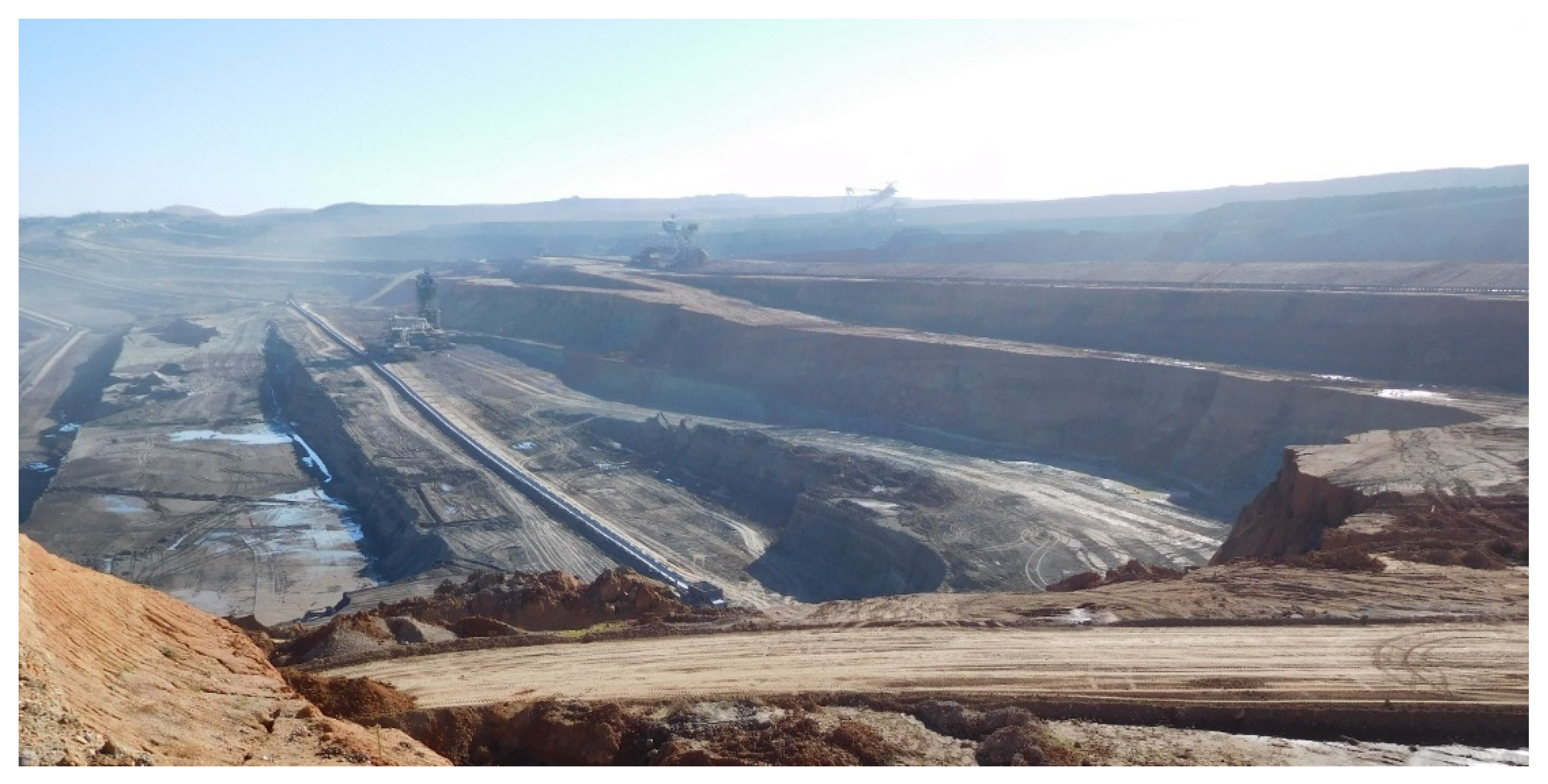
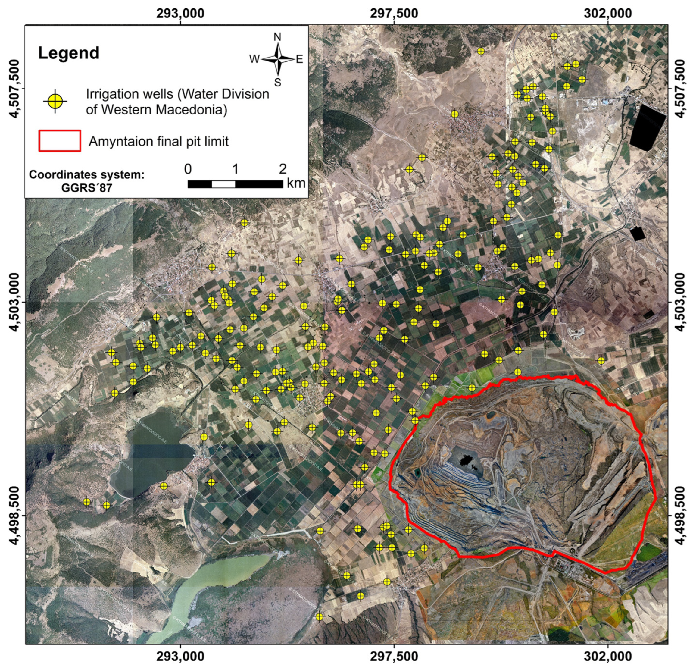
2. The Amyntaion Mining Area

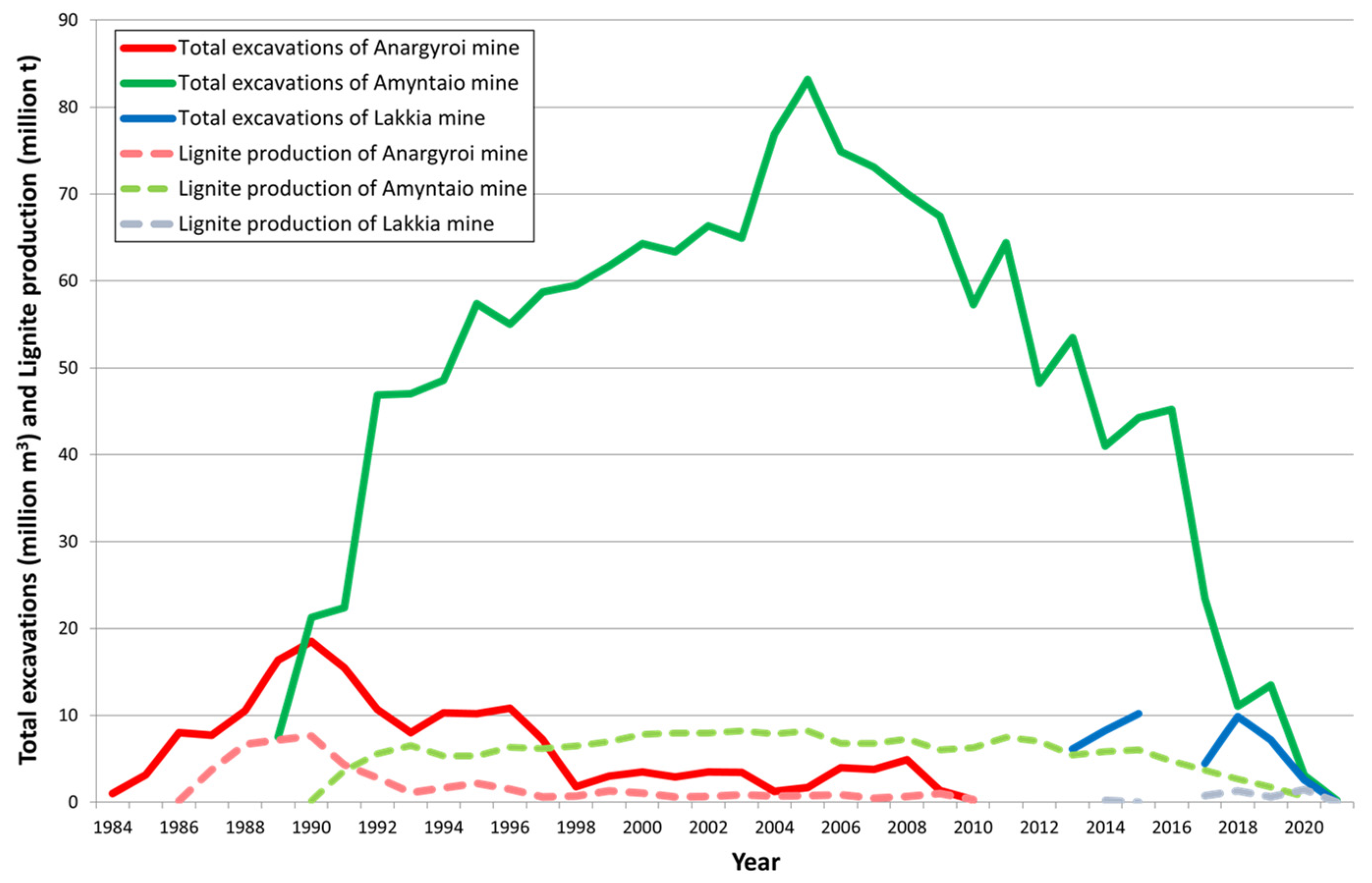
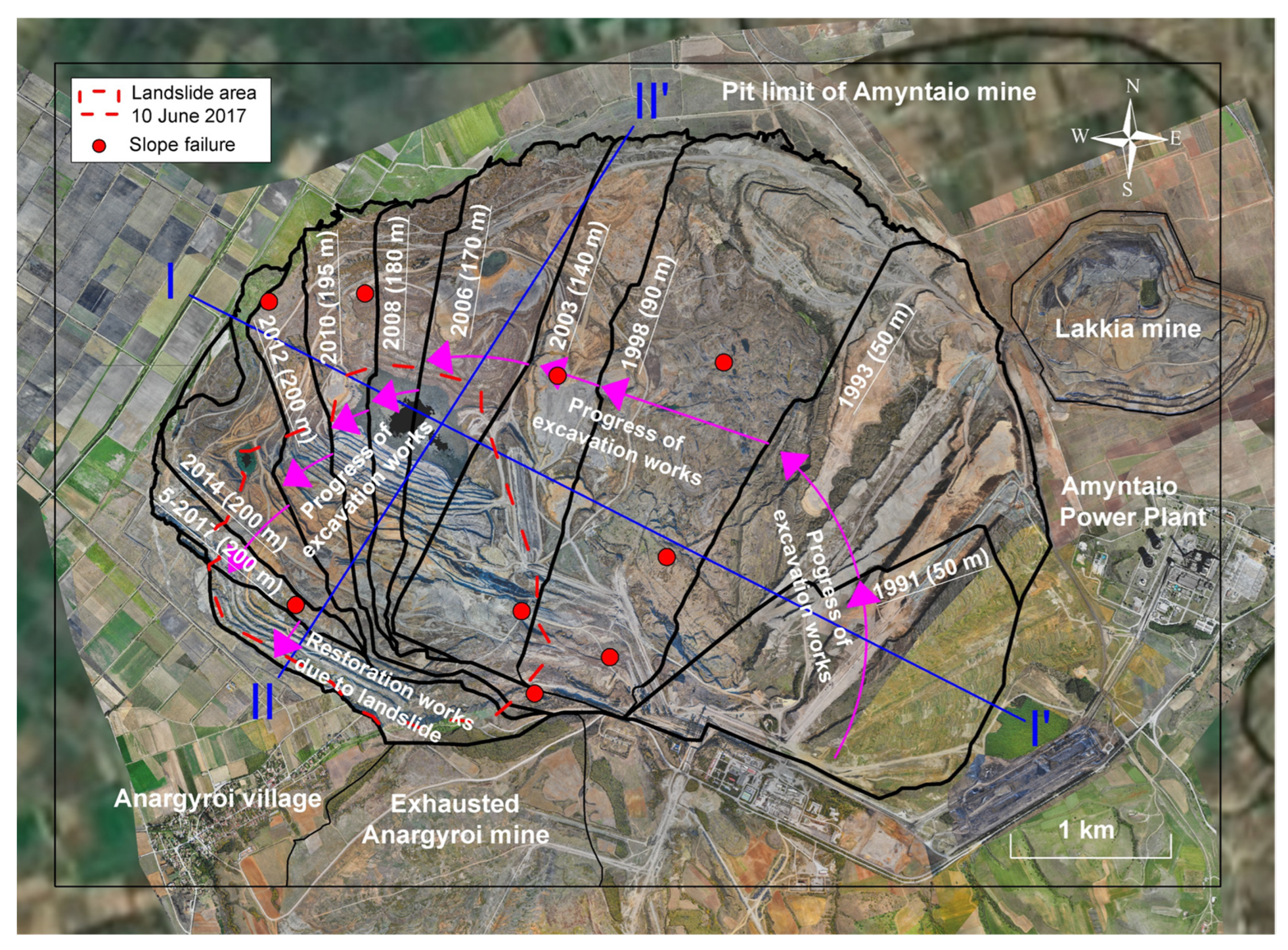
2.1. Historical Data—Reclamation Planning

Public Power Corporation (PPC) of Greece operates several mines in the large lignite fields of Western Macedonia using mainly continuous (bucket wheel excavators—spreaders—belt conveyors) and occasionally non-continuous (trucks—loaders) mining techniques. In the Amyntaion area, three surface lignite mines have been exploited in the last 35 years: (a) the Anargyroi mine between 1984 and 2010, with 49 million tons of lignite production and 173 million m3 total excavations, (b) the Amyntaion mine between 1989 and 2020, with 179 million tons of lignite production and 1595 million m3 total excavations, and (c) the smaller, but higher quality, Lakkia mine, between 2013 and 2021, with 4 million tons of lignite production and 49 million m3 total excavations. A total of 232 million tons of lignite has been mined in the Amyntaion area, with total excavations of 1817 million m3 and an overall stripping ratio (steriles to lignite) of 7 m3 per ton of lignite.
Figure 2 shows a plan of the Amyntaion area mines in the Amyntaion flood plain, extending from SW to the NE along the four natural lakes shown in the figure. The piezometric regime of the flood plain practically reaches ground level and has a very mild inclination from SW (Cheimaditida and Zazari lakes at elevation ca. +595) towards the NE (Petron Lake at elevation ca. +570) over a distance of about 15 km.
Figure 3 shows the elevation distribution in the mining area and the internal and external spoil dumping areas through the hillshade effect. The brown (higher elevation) area in the south is the external spoil dumping site. The bluish color shows the deeper part of the present Amyntaion mine. Yellow sections A and B show the sections analyzed for slope stability.
Figure 4 shows the total annual excavation volumes (full lines) and lignite production (dashed lines) in the three mines of the Amyntaion area. The green line corresponds to the case study (Amyntaion mine).
Figure 5 shows the progress of the excavation work (location of the upper exploitation front) and the corresponding maximum depths of the Amyntaion mine over time. The red points show cases of slope failures that occurred through time in the mining area, whereas the orange dashed polygon shows the landslide area of the 10 June 2017. Figure 6 shows two typical cross-sections (I-I and II-II) of the Amyntaion mine (section locations are shown in Figure 5).
In the initial exploitation stages, sterile materials from the Anargyroi and Amyntaion mines were deposited in the external dumping area to the south of the mines; with the progress of mining excavations, spoils were deposited inside the pits, backfilling the mines. Complete backfilling of the Anargyroi pit with materials from the Anargyroi and the Amyntaion mines was achieved in 2016. In 2013, extraction started in the smaller (but better quality) Lakkia mine, with spoils transported for environmental reclamation of the Anargyroi and Amyntaion mines. Up to the present time, an area of about 8 km2 has been reclaimed for forestry and 1 km2 for agriculture.
In June 2017, a significant landslide (about 80 million m3) occurred on the southwestern exploitation front of the Amyntaion mine, despite its very mild slope inclination (milder than 1:6). According to the geotechnical study for the rehabilitation of the affected area [20], which practically coincided with the decision to decommission the Amyntaion mine as part of the national decarbonization policy, the failed slope was regraded to eliminate abrupt drops created by the failure and the mine was decommissioned in July 2020. Planning for land re-use after decommissioning, combined geotechnical and geochemical studies to examine the feasibility of creating an aquatic ecosystem, by allowing the natural filling of the mine pit from precipitation and groundwater seepage.

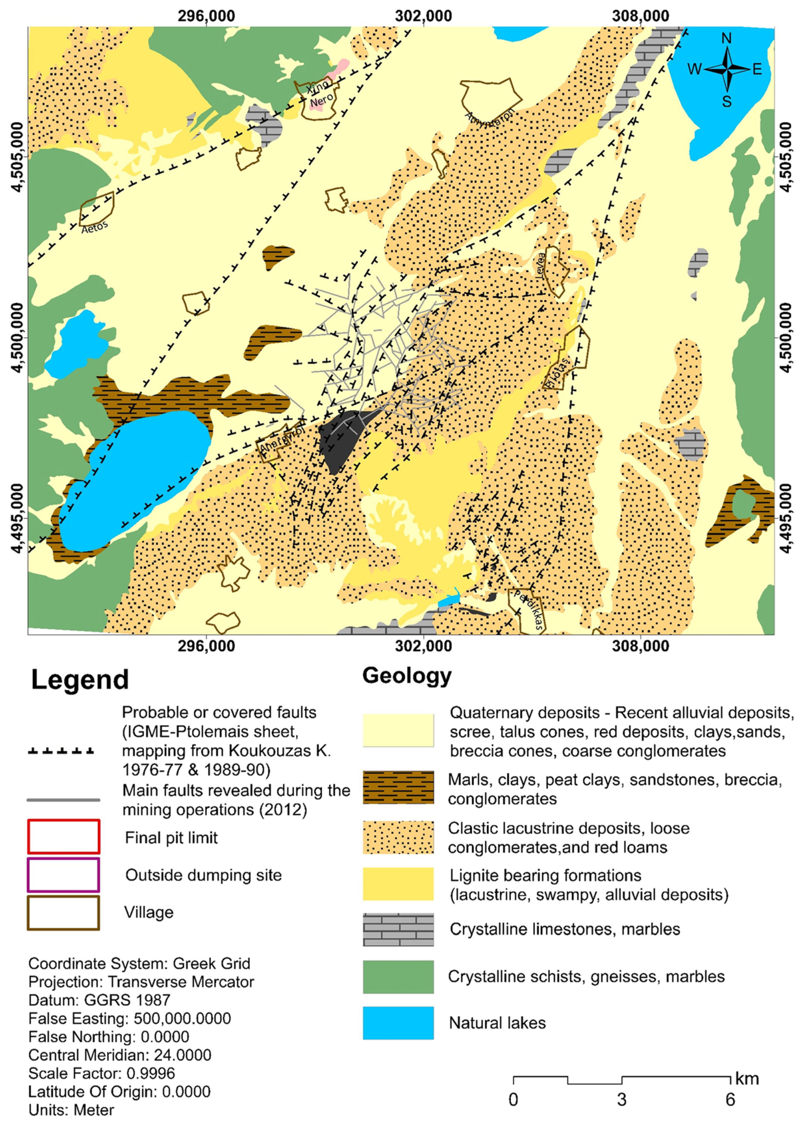
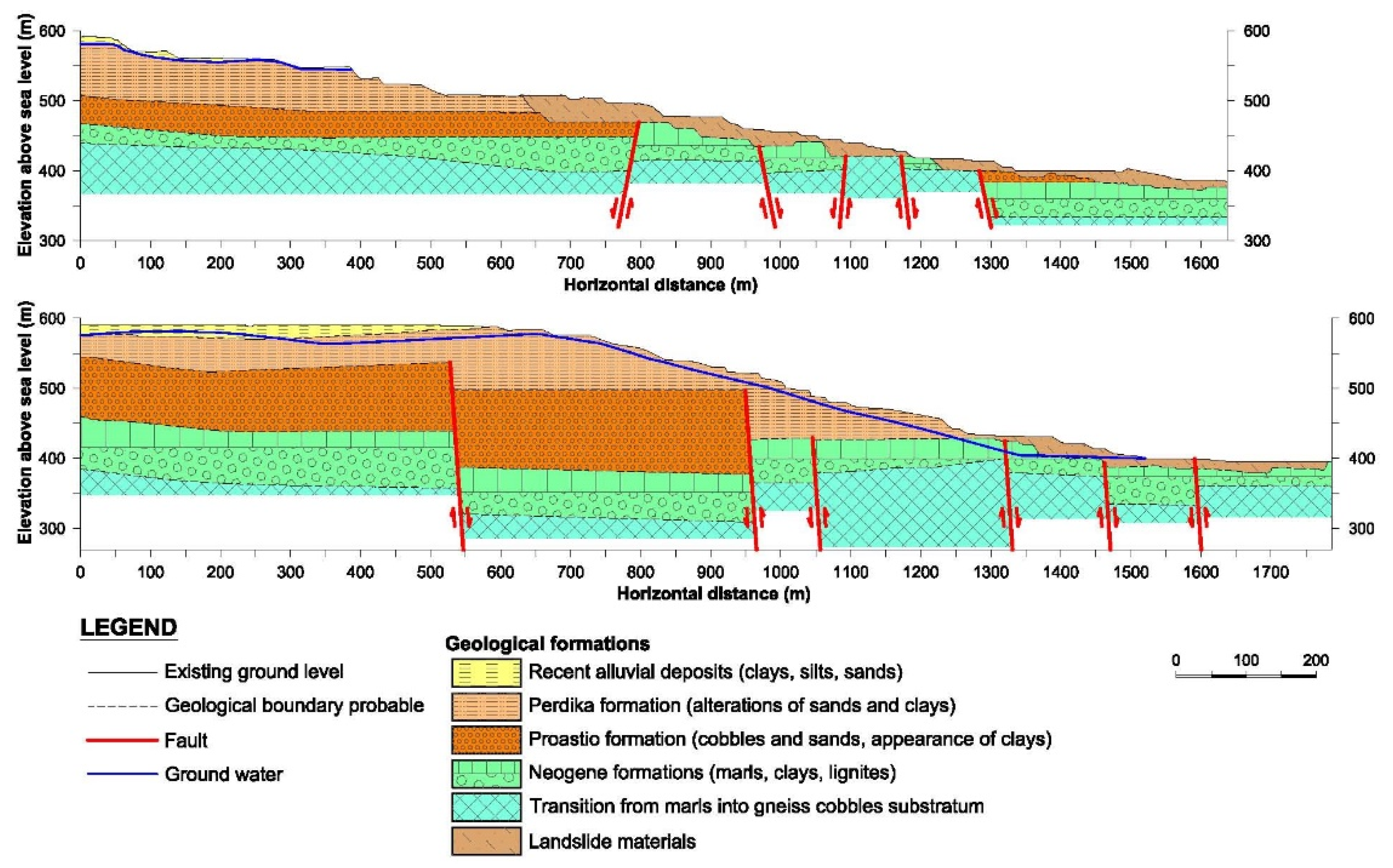
2.2. Geological, Geotectonic, and Hydrogeological Setting

Figure 7 shows a simplified geological map of the Amyntaion basin with the mining area in the red envelopes (see also Figure 3). The Amyntaion basin is a deep tectonic trough (up to 500 m deep) in the SW-NE direction in the Pelagonic geotectonic zone, consisting of an upper Palaeozoic bedrock (metamorphic rocks including schists, crystalline schists, and gneiss) and a Middle Triassic—Lower Jurassic carbonate cover (marbles, crystalline limestones, and tectonic breccias). In the Neogene, the trough was filled with lacustrine-marshy sediments (including the lignite-bearing horizons) and was subsequently covered with fluvial-lacustrine sediments in the Quaternary.
According to the geologic map of Greece [21], the Neogene sediments include an upper lignite-bearing (Ptolemaida) formation of Pliocene age (about 50–100 m thick) which also includes lacustrine-marshy deposits of grey to grey-green silty clays and clayey sands, and a lower lignite-bearing (Komnina) formation of upper Miocene-lower Pliocene age (over 200 m thick), which also includes lacustrine-marshy deposits of silty clays and sandy layers with intercalations of sandstones, above a thick base of steriles including horizons of clay-marls, sandy clays, and sands.
The Quaternary deposits, mainly of Low-Middle Pleistocene age, have a thickness of about 80–120 m and include an upper (Perdika) formation (including fluvial-lacustrine sediments comprised of intercalations of fine sand with alternating layers of sandy clays, clays, and marls, as well as lenticular intercalations of weakly cemented conglomerates created by small-sized pebbles) and a lower (Proastion) formation which overlies the Neogene deposits with unconformity and includes alternating horizons of loose silty to clayey sands and conglomerates cemented with red clay [22].
Since the Middle-Upper Miocene, extensional neotectonic activity prevails in the area, shaping the large Florina–Ptolemaida basin by major normal faults in the NW–SE direction; later, the second group of NE-SW faults created secondary troughs, one of which is the Amyntaion basin [23,24,25,26]. Six major fault zones control the Amyntaion lignite mining area, and they constitute decisive factor for the overall mine stability, as their complex character cause fragmentation to the geological formation and decrease of their cohesion [27].
The Amyntaion flood plain is intensely cultivated. Irrigation during the dry (summer) season is achieved by about 600 deep pumped wells (shown in Figure 8), which penetrate the upper (quaternary), higher permeability, aquifer to depths up to about 120 m.
Changes between limnic and telmatic environments are responsible for the lignite formations of the Amyntaion-Ptolemaida deposit. This deposit occurs in an alternating nature between lignite and interburden [28].
The ca. 200 m deep Amyntaion mine uses peripheral pumped wells to reduce groundwater seepage on the exploitation slopes. These wells penetrate the upper (more permeable) aquifer to a depth up to 120 m. The underlying lignite and intermediate sterile zone are relatively impermeable and do not need dewatering. Calculations and measurements show that the ca. 100 m deep lowering of the upper aquifer along the perimeter of the mine influences a zone up to about 500 m beyond the crest of the mine. In the rest of the flood plain, groundwater table lowering is due to the many deep wells for irrigation purposes. Since 2019, when mining operations stopped, pumping from the peripheral dewatering wells of the mine was discontinued, and pumping from the bottom of the pit stopped when the mine was decommissioned in July 2020.
According to the planning studies for the closure of the Amyntaion mine, new land uses will be created in the area surrounding the pit lake, such as recreational parks, wildlife, industrial areas, and photovoltaic parks. According to the references [29,30] the expected rise of the water level in the Amyntaion artificial lake from the initial (2020) level of +390, corresponding to the bottom of the pit, up to the final equilibrium level (about +540) after more than 100 years. It is observed that the lake development is distinguished into three stages; the early one, where the lake begins to be filled at a big rate ( 10   m per year for the first 10 years), since the surface area of the pit is smaller at deep levels, the second phase of a more normal rate of filling and the third where the raise rate has begun to be stabilized ( 0.1   m per year). The expected trend evolution was calculated through a spatiotemporal forecasting model, which considers the crucial parameters of rainfall and temperature and by applying linear (autoregressive integrated moving average) and non-linear methods (artificial neural networks) [29,30].

3. Stability of Surface Lignite Mining Slopes after Closure

This section develops a simplified analytical tool for the calculation of the evolution of the safety factor of surface lignite mining slopes after closure, as the water level in the pit lake rises.
References [31,32] describe the geotechnics of surface lignite mining slopes in Western Macedonia. Typical ground profiles include a thick (50–120 m) zone of sterile overburden consisting of Quaternary and Neogene sediments overlying the exploitable deposits (30–130 m thick), giving a total depth of the mine up to about 250 m. The exploitable deposits include lignite seams, each several meters thick, separated by sterile interlayers consisting of hard clays/marls, usually with medium (15–35%) to high (35–50%) carbonate content. The sterile interlayers have a thickness varying between a few millimeters and several tens of centimeters (occasionally even several meters). Steriles with lower carbonate content (less than 15%) usually have high plasticity (PI > 30–40%), low peak friction angle (18–22 degrees), and an even lower residual friction angle (15–20 degrees). Steriles with medium to high carbonate content usually have lower plasticity (PI = 10–30%), higher peak friction angle (22–26 degrees), and residual friction angle in the range of 16–24 degrees.
Experience of the study area shows that instabilities of the exploitation fronts and the permanent (final) slopes are usually initiated by, or associated with, the development of a planar sliding surface along with a weak (i.e., having lower shear strength) sub-horizontal lignite-to-clay/marl interface, located either slightly above or (more often) slightly below the base of the slope. Sliding along such a surface is usually initiated by the significant horizontal stress release as the excavation front is advanced, in conjunction with the high stiffness contrast between stiffer lignite zones and much softer intermediate steriles. The elastic shear deformation along such interfaces increases with depth (due to the larger stress release) and, in deep mines, it may exceed the peak shear strength, leading to even larger deformations as the shear strength gradually drops towards the (lower) residual value. If the residual shear strength is not sufficient to provide the required shearing resistance for the stability of the sliding mass, slope instability occurs. Due to the above sliding mechanism, movement in such slopes starts at a slow velocity and gradually accelerates, eventually leading to failure. Local experience shows that the velocity of the movement is not usually a reliable criterion for incipient instability (via a critical velocity), as long as the velocity is practically stable or varies in a consistent manner (e.g., influenced by rainfall). It appears that the acceleration rate of slope movement is a more reliable criterion in accessing upcoming instability: sustained velocity changes per day approaching the velocity of the previous day are usually alarming.
The inclination of the above sub-horizontal interfaces is critical for slope stability; in deep mines, even a mild dip towards the toe of the slope can reduce the safety factor significantly, compared to a horizontal interface and, even more, compared to interfaces with reverse inclination (towards the slope interior). In some cases, when the lignite seams are highly tectonized (as usually occurs close to the edges of the tectonic trough), the above weak interfaces are disturbed by successive faults and become discontinuous; in such cases, slope instabilities occur along a more or less circular or multi-linear failure surface which may locally align with weak interfaces, where kinematically possible.
Finally, the rate of filling of the pit lake is also critical in slope stability. Rapid filling of the pit lake is always beneficial for stability (compared to slower filling rates) because, in the rapid filling, the stabilizing effect of the lake water pressure acting on the slope occurs faster than the destabilizing effect of the rising pore water pressure inside the slope). Unfortunately, this condition cannot be controlled in most cases, because the expected filling rate of the lake may be delayed by unusual dry seasons and, most importantly, the rate of increase of the pore water pressure in the slope may be accelerated by the presence of undetected high permeability zones. Thus, the present analysis assumes (conservatively) that the piezometric regime in the slope corresponds to steady-state seepage conditions for each pit lake level, i.e., filling of the pit lake is sufficiently slow that pore pressure equilibrium is achieved in the slope.
Based on the above mechanisms, the present investigation studies the effects of the following parameters on slope stability conditions after mine closure with pit lake development:
1.
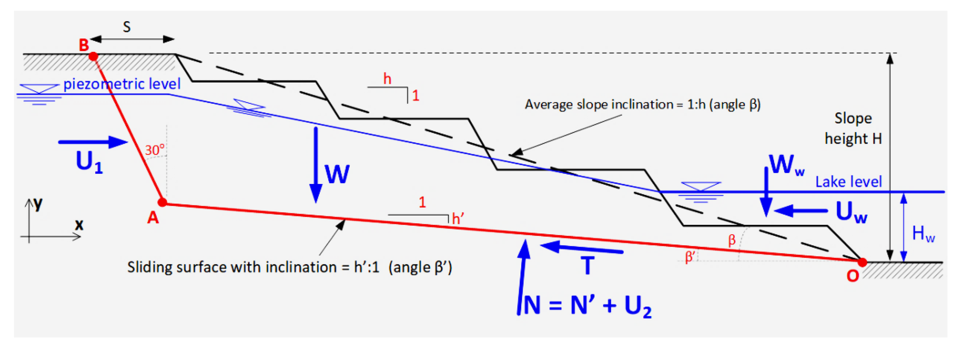
The height (H) and average inclination of the slope (angle β, from crest to toe). Although the overall slope consists of several benches and drops, overall slope stability is controlled by the average slope inclination rather than the size of the intermediate benches and drops.
2.
The inclination (angle β’) with respect to the horizontal of the lignite-bearing layers and intermediate steriles in the slope. In slopes with few tectonic faults, potential failure surfaces usually follow such interfaces because of their lower shear strength. In contrast, in heavily tectonized materials, failure surfaces are more or less circular, crossing interfaces, since aligning with them is not kinematically feasible.
3.
The shear strength (especially the residual strength) parameters (c’, φ’) of the ground along the failure surface, with emphasis on the residual strength along with weak interfaces between lignite-bearing layers and underlying steriles (in slopes with few tectonic faults).
4.
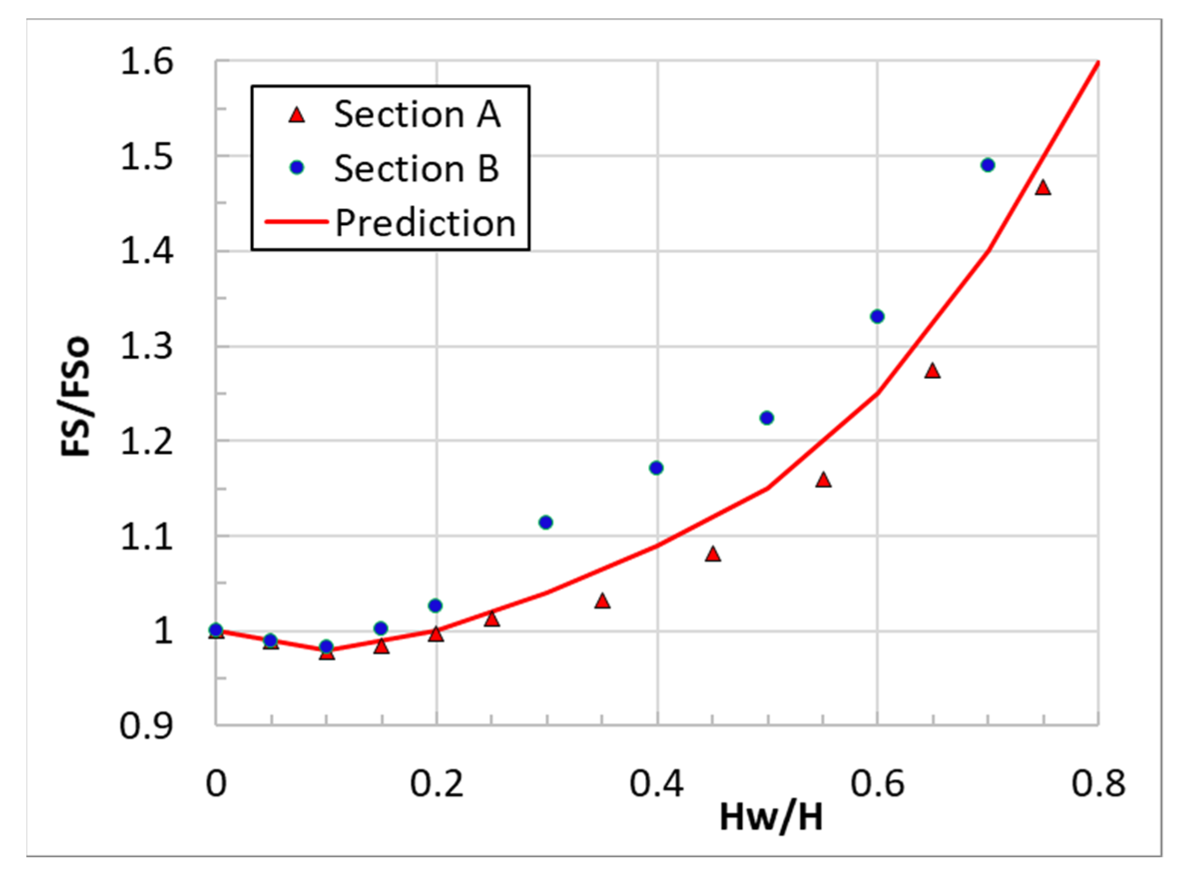
The temporal evolution of the piezometric levels in the slope, as the water level in the pit lake (depth Hw) rises, in conjunction with the stabilizing effect of the pressure of lake water acting on the lower part of the slope.
Various methods have been used in the literature for the analysis of mining slope stability during exploitation. Analytical methods (e.g., [32]), produce a relatively simple formula for the safety factor of the slope and thus can illustrate better the effect of various input parameters. Numerical methods using suitable software (e.g., [33]) can model complicated geometric and material characteristics more accurately but lack insight on the sensitivity of the results on the various input parameters. Most of these methods, however, do not study the effect of the rising water level in the pit lake after mine closure, because they are developed for the stability of mining slopes during operation. The following analytical method is developed to study the overall stability of mining slopes as the water level in the pit rises. The method produces an analytical formula for the safety factor as a function of the water level in the pit lake and can be used for preliminary assessments of mine closures.
Figure 9 shows the geometry and the forces acting on a typical sliding mass (OAB) of a surface lignite mining slope (height H , average inclination angle β tan ( β ) = 1 / h ). Assuming the experience, such slope failures usually emerge close the toe of the slope (O) and develop along with a sub-horizontal lignite-marl interface (OA) with angle   β ( β ,   tan   β = h ) with respect to the horizontal. Experience also shows that stability conditions are more adverse, as the inclination of OA increases (h’ increases). In some cases, the material is intensely tectonized (i.e., line OA is crossed by several tectonic faults), and the development of a planar failure surface (OA) is not possible kinematically. In such cases, failure occurs along a quasi-circular surface and the below analytical method is not applicable.
The sliding surface is assumed to reach the top of the slope, at distance ( S ) from the crest, with a planar transition ( AB ). It is assumed that a tension crack develops along (AB), only a water thrust ( U 1 ) acts on ( AB ) and that (AB) has an inclination of 30 degrees to the vertical plane (the inclination of (AB) has a small effect on the stability calculations). The blue line in the figure shows the assumed piezometric level along the failure surface (OAB). A linear transition of the piezometric surface is assumed between the crest of the slope (ambient piezometric level) and the pit lake level. It is noted that other aquifers which may develop at higher elevations in the slope are irrelevant in the slope stability analysis.
Geometrical considerations give the horizontal (X) and vertical (Y) projections of lines (AB) and (OA):
X ( AB ) = X 1 = ( 1 - hh ) H - h S 3 - h                     Y ( AB ) = Y 1 = 3 X 1
X ( OA ) = X 2 = ( 3 h 1 ) H + 3 S 3 - h                     Y ( OA ) = Y 2 = h X 2
( OA ) = L = ( X 2 ) 2 + ( Y 2 ) 2
The tension crack ( AB ) is assumed to be filled with water (unit weight γ w ) at a fraction λ 1 (between 0 and 1) of its total height Υ 1 . Thus, the water force on (AB) is:
U 1 = 1 2 γ w ( λ 1 Υ 1 ) 2
Considering that the pore water pressure at A is: u A = λ 1 γ w Υ 1 and the pore water pressure at O is: u o = γ w H w , with linear variation in between, the pore water force (U2) acting on the base ( OA ) of the sliding mass is:
U 2 = 1 2 γ w ( H w + λ 1 Υ 1 ) L
where L is the length of the sliding surface OA
The lake water forces W w and U w acting at the toe of the slope are:
U w = 1 2 γ w ( H w ) 2  
W w = hU w
where H w is the height of the lake’s water depth
The weight ( W ) of the sliding mass is:
W = 1 2 γ w [ S ( Y 1 + Y 2 ) + X 2 Y 1 - X 1 Y 2 ]
Force equilibrium of the sliding mass along axes normal and parallel to its base (OA) gives:
N = ( W + W w ) cos β + ( U w - U 1 ) sin β
T = ( W + W w ) sin β + ( U 1 - U w ) cos β
Finally, the shearing resistance ( T u ) along the base (OA) of the sliding mass is the sum of the cohesive and frictional components:
T u = c L + ( N U 2 ) tan φ
where ( φ , c ) are the effective friction angle and the effective cohesion along the base of the sliding mass (along with an interface between a lignite zone and the underlying stiff plastic clay-marl layer).
Equations (8) and (9) to (10) can be used to calculate the overall safety factor ( FS ) of the slope:
FS T u T = c L + [ ( W + W w ) cos β + ( U w - U 1 ) sin β ] tan φ   -   U 2 tan φ ( W + W w ) sin β + ( U 1 - U w ) cos β
and the value of the safety factor (FSo) before the lake level rises (Hw = 0):
FS o T u T = c L + [ W   cos β -   U 1 sin β ] tan φ   -   U 2 tan φ W   sin β + U 1 cos β
Note: In Formulae (11) and (12), the pore water force (U2) is different, as it depends on the depth ( H w ) of the pit lake (see Equation (5)).
Application of Formulae (11) and (12) for various combinations of geometrical ( H ,   H w ) , h , h , λ 1 , S ) and material ( γ w , c , φ) parameters shows that while the values of ( FS ) and ( FS o ) depend on all input parameters, the ratio ( FS / FS o ) is weakly dependent on input parameters other than the ratio ( H w /H) and the inclination angle (β’). The reason for the weak dependency of the ratio ( FS / FS o ) on the various geometric and material parameters is that the effect of these parameters is expressed in both components ( FS and FS o ) in the same way (i.e., tends to increase or decrease both values) and thus their influence of the ratio FS / FS o is significantly reduced.
Using the above analytical method, Figure 10 plots the calculated safety factor ( FS ) of a slope with height H and lake water depth ( H w ), normalized with the safety factor ( FS o ) of the same slope for H w = 0, versus the ratio ( H w / H ) for all examined cases in the following ranges: H = 150–250 m, h = 4–6, λ 1 = 0.90, S / H = 0.10, γ w = 10 kN/m3, c = 3–5 kPa, φ = 17–25 deg). For each case, the combinations of the various parameters were such, that the safety factor during operation of the mine was in the range FS o = 1.20 1.35 , the typical range of safety factors in exploitation slopes for surface lignite mines in Greece.
The curves in the figure correspond to various inclinations of the base (OA) of the failure surface (   β = 0–4 deg). The figure shows that as the water level in the lake rises, the safety factor reduces, reaching a minimum value when H w / H = 0.2 to 0.35. The reduction of the safety factor ( FS ) with respect to FS o is smallest (about 10%) when the base of the failure surface is horizontal (   β = 0) and increases up to about 25% when this inclination reaches 4 degrees. Subsequently, the safety factor increases monotonically, exceeds the value FS o when H w / H > 0.40 to 0.65, and reaches large values when the slope becomes fully submerged.
In real lignite slopes, the reduction of the safety factor ( FS ) at low levels of the pit lake is expected to be smaller than the above simplified analysis, because the base of the sliding mass (several hundred meters long) is rarely perfectly planar and uniformly inclined, as assumed in the analysis. The next section of the paper presents the results of more realistic numerical analyses which show that the maximum reduction of the safety factor does not exceed 5% of the initial value ( FS o ) in more realistic cases of the geometry of the failure surface, where the failure surface crosses some material boundaries rather than following a single interface.

4. Stability of the Amyntaion Mine Slopes after Closure

The stability of the Amyntaion mine slopes was analyzed at two representative Sections A and B (locations shown in Figure 3) as the water level in the pit lake rises. Both Sections are close to the SW corner of the mine because the depth of the mine is maximum there, the steepest slope is at Section A and the significant landslide of 2017 occurred close to and along the direction of Section B. Figure 11 presents the geological profiles of Sections A and B. Both Sections are crossed by several tectonic faults (shown in red) because the slopes are close to the edge of the tectonic trough, which is defined by several tectonic faults. Since the deposits are highly tectonized, potential failure surfaces are not expected to develop along with a single weak lignite-sterile interface, as examined analytically in the previous section of the paper. On the contrary, potential failure surfaces are expected to be more or less circular, cutting through the various deposits shown in the geological sections.
Table 1 shows the strength parameters of the relevant geological formations, based on past experience from back analyses on similar slopes (either failed or approaching failure) and the literature [34]. The piezometric surface along the examined failure surfaces was assumed to be very close to the ground surface (at a depth of about 10 m).
The numerical stability analyses of the two slopes (A and B) with variable pit lake levels and corresponding equilibrium piezometric levels in the slope were performed with a 2D limit equilibrium method (method of slices) using the computer software SLIDE2 (2D Limit Equilibrium Analysis for Slopes), [35].
Figure 12 and Figure 13 show the critical failure surfaces and the corresponding calculated safety factors at the end of mine operation (when the piezometric level was at the bottom of the pit) and at an elevated water level in the pit lake when the safety factor is at a minimum (before starting to increase).
Figure 14 plots the variation of the calculated safety factor (FS) with depth (Hw) of the pit lake for Sections A and B and a “predicted” (average) curve. For the calculations, the same input parameters were used for the two sections. The safety factor (FS) is normalized with the safety factor ( FS o ) of the same slope when Hw = 0. Both sections show similar responses, despite the very significant difference in the initial safety factor ( FS o = 1.294 in Section A and FS o = 1.879 in Section B) which is mainly due to the difference in the two slope inclinations (1:4 and 1:7). The safety factor decreases slightly (by about 2%) up to lake depth about Hw = (10–15%) H and then increases monotonically, confirming that the overall safety of the slope increases as the water depth in the lake increases. The small initial decrease and the subsequent significant and monotonic increase of the safety factor of the slopes with increasing lake water level are due to the fact that the piezometric level along the critical failure surface at the end of the operation of the mine is high (almost up to ground level) due to the low permeability of the Neogene deposits and the underlying base marl. Thus, when the water level in the pit lake rises, the destabilizing increase of the pore water pressure along the failure surface is relatively small, compared to the stabilizing effect of the lake water thrust acting at the toe of the slope.

5. Conclusions

This paper investigates the evolution of the safety factor of surface lignite mining slopes after mine closure, as the water level in the pit lake rises. A simplified analytical model calculates the safety factor of such slopes, assuming that the base of the failure surface develops along a weak lignite-to-sterile interface, located close to the base of the slope. The analysis shows that the safety factor (FS) of the slope can be expressed in terms of the initial safety factor ( FS o ) before the water level starts to rise in the lake, the ratio (Hw/H) of the depth of the lake to the height of the slope and the inclination (β’) of the weak interface at the base of the slope. Parametric analyses have shown that the effect of the remaining geometrical and material parameters can be lumped into the initial safety factor ( FS o ) with reasonable accuracy. In the initial stages of water filling, the safety factor of the slope decreases mildly and then increases significantly. The simplified analytical model shows that the minimum safety factor is controlled by the inclination (β’) of the weak interface at the base of the slope and ranges between 10–25% of the initial safety factor ( FS o ) . In real slopes, the reduction of FS is expected to be appreciably smaller, because the base of the sliding mass is rarely perfectly planar and uniformly inclined, as assumed in the simplified analysis.
The same trends are confirmed by numerical stability analyses of two characteristic slopes of the Amyntaion mine in Western Macedonia, Greece, which was decommissioned in 2020 and the water level in the pit lake is rising ever since. The numerical analyses show that the maximum reduction of the safety factor does not exceed 5% of the initial value ( FS o ) and occurs at lake depths about 10–15% of the slope height. Subsequently, the safety factor quickly recovers to the initial value ( FS o ) and then increases rapidly, almost doubling when the slope is practically submerged. The small initial decrease and the subsequent significant and monotonic increase of the safety factor of the slopes with increasing lake water level are due to the fact that the piezometric level along the critical failure surface at the end of the operation of the mine is high (almost up to ground level) due to low ground permeability. Thus, the destabilizing pore water pressure rise along the failure surface is relatively small, compared to the stabilizing effect of the lake water acting on the slope.
Both methods of analysis (analytical and numerical) have used the conservative assumption that the piezometric regime in the slope corresponds to steady-state seepage conditions for each pit lake level, i.e., filling of the pit lake is sufficiently slow that pore pressure equilibrium is achieved in the slope. This assumption is conservative, since faster filling of the pit lake is beneficial for stability, because the stabilizing effect of the lake water pressure acting on the slope occurs faster than the destabilizing effect of the rising pore water pressure inside the slope. Unfortunately, this condition cannot be controlled in most cases, because the expected filling rate of the lake may be delayed by unusual dry seasons and, most importantly, the rate of increase of the pore water pressure in the slope may be accelerated by the presence of undetected high permeability zones.

Author Contributions

Conceptualization, C.R. and M.K.; methodology, M.K. and C.R.; software, M.K., C.R., A.S. and N.P.; validation, M.K., C.R., A.S. and N.P.; formal analysis, M.K., C.R., A.S. and N.P.; investigation, M.K., C.R., A.S. and N.P.; resources, M.K., C.R., A.S. and N.P.; data curation, M.K., C.R., A.S. and N.P.; writing—original draft preparation, M.K. and C.R.; writing—review and editing M.K., C.R., A.S. and N.P.; visualization, M.K., C.R., A.S. and N.P.; supervision M.K. and C.R.; project administration, M.K. and C.R. All authors have read and agreed to the published version of the manuscript.

Funding

This research received no external funding.

Conflicts of Interest

The authors declare no conflict of interest.

References

  1. Tao, Z.; Li, M.; Zhu, C.; He, M.; Zheng, X.; Yu, S. Analysis of the Critical Safety Thickness for Pretreatment of Mined-Out Areas Underlying the Final Slopes of Open-Pit Mines and the Effects of Treatment. Shock Vib. 2018, 2018, 1306535. [Google Scholar] [CrossRef] [Green Version]
  2. De Graaf, P.; Beale, G.; Carter, T.; Dixon, J. Geotechnical Guidelines for Open Pit Closure—A New Publication by the Large Open Pit (LOP) Project. In Mine Closure 2021: Proceedings of the 14th International Conference on Mine Closure; Fourie, A.B., Tibbett, M., Sharkuu, A., Eds.; QMC Group: Ulaanbaatar, Mongolia, 2021; pp. 217–230. [Google Scholar] [CrossRef]
  3. Agboola, O.; Babatunde, D.E.; Isaac Fayomi, O.S.; Sadiku, E.R.; Popoola, P.; Moropeng, L.; Yahaya, A.; Mamudu, O.A. A Review on the Impact of Mining Operation: Monitoring, Assessment and Management. Results Eng. 2020, 8, 100181. [Google Scholar] [CrossRef]
  4. McCullough, C.; Schultze, M.; Vandenberg, J. Realizing Beneficial End Uses from Abandoned Pit Lakes. Minerals 2020, 10, 133. [Google Scholar] [CrossRef] [Green Version]
  5. Doupé, R.G.; Lymbery, A.J. Environmental Risks Associated with Beneficial End Uses of Mine Lakes in Southwestern Australia. Mine Water Environ. 2005, 24, 134–138. [Google Scholar] [CrossRef]
  6. McCullough, C. Key Mine Closure Lessons Still to Be Learned. In Mine Closure 2016: Proceedings of the 11th International Conference on Mine Closure; Fourie, A.B., Tibbett, M., Eds.; Australian Centre for Geomechanics: Perth, Australia, 2016; pp. 325–338. ISBN 978-0-9924810-4-9. [Google Scholar] [CrossRef] [Green Version]
  7. Vandenberg, J.; Mccullough, C. Global Review of Pit Lake Case Studies; Presentation of Golder Associates Inc. British Columbia MEND ML/ARD Annual Workshop: Vancouver, BC, Canada, 2018; Available online: https://bc-mlard.ca/files/presentations/2018-8-VANDENBERG-MCCULLOUGH-review-pit-lake-case-studies.pdf (accessed on 22 April 2022).
  8. de Graaf, P.; Desjardins, M.; Tsheko, P. Geotechnical Risk Management for Open Pit Mine Closure: A Sub-Arctic and Semi-Arid Case Study. In Mine Closure 2019: Proceedings of the 13th International Conference on Mine Closure; Fourie, A.B., Tibbett, M., Eds.; Australian Centre for Geomechanics: Perth, Australia, 2019; pp. 211–234. [Google Scholar] [CrossRef] [Green Version]
  9. Desjardins, M.; de Graaf, P.; Beale, G.; Rougier, M. Geotechnical Risk Management for Victor Mine Closure. In Slope Stability 2020: Proceedings of the 2020 International Symposium on Slope Stability in Open Pit Mining and Civil Engineering; Dight, P.M., Ed.; Australian Centre for Geomechanics: Perth, Australia, 2020; pp. 399–414. [Google Scholar] [CrossRef]
  10. Botham, N.; Kelso, C.; Annegarn, H. Best Practice in Acquiring a Mine Closure Certificate—A Critical Analysis of the De Beers Oaks Diamond Mine, South Africa; Australian Centre for Geomechanics: Perth, Australia, 2011; pp. 401–410. [Google Scholar] [CrossRef]
  11. Bednarczyk, Z. Slope Stability Analysis for the Design of a New Lignite Open-Pit Mine. Procedia Eng. 2017, 191, 51–58. [Google Scholar] [CrossRef]
  12. Apostu, I.-M.; Lazar, M.; Faur, F. A Suggested Methodology for Assessing the Failure Risk of the Final Slopes of Former Open-Pits in Case of Flooding. Sustainability 2021, 13, 6919. [Google Scholar] [CrossRef]
  13. Fidalgo Valverde, G.; Duda, A.; Iglesias Rodríguez, F.J.; Frejowski, A.; Todorov, I. Groundwater Risk Assessment in the Context of an Underground Coal Mine Closure and an Economic Evaluation of Proposed Treatments: A Case Study. Energies 2021, 14, 1671. [Google Scholar] [CrossRef]
  14. Komljenovic, D.; Stojanovic, L.; Malbasic, V.; Lukic, A. A Resilience-Based Approach in Managing the Closure and Abandonment of Large Mine Tailing Ponds. Int. J. Min. Sci. Technol. 2020, 30, 737–746. [Google Scholar] [CrossRef]
  15. Anim, F.; Nyankson, E.; Nyame, F.K. Analysis of Mine Water from Four Decommissioned Pits in South-Western Ghana–Implications for Remediation Programmes for Mine Closure. Water Policy 2017, 19, 957–977. [Google Scholar] [CrossRef] [Green Version]
  16. Triantafyllidis, S.; Psarraki, D. Implementation of Geochemical Modeling in Post-Mining Land Uses, the Case of the Abandoned Open Pit Lake of the Kirki High Sulfidation Epithermal System, Thrace, NE Greece. Environ. Earth Sci. 2020, 79, 518. [Google Scholar] [CrossRef]
  17. Johnstone, A.C. Are Pit Lakes an Environmentally Sustainable Closure Option for Opencast Coal Mines? J. S. Afr. Inst. Min. Metall. 2021, 121, 1–5. [Google Scholar] [CrossRef]
  18. Sakellari, C.; Roumpos, C.; Louloudis, G.; Vasileiou, E. A Review about the Sustainability of Pit Lakes as a Rehabilitation Factor after Mine Closure. Mater. Proc. 2021, 5, 5052. [Google Scholar] [CrossRef]
  19. Gaagai, A.; Aouissi, H.A.; Krauklis, A.E.; Burlakovs, J.; Athamena, A.; Zekker, I.; Boudoukha, A.; Benaabidate, L.; Chenchouni, H. Modeling and Risk Analysis of Dam-Break Flooding in a Semi-Arid Montane Watershed: A Case Study of the Yabous Dam, Northeastern Algeria. Water 2022, 14, 767. [Google Scholar] [CrossRef]
  20. Kavvadas, M. Report for the Slope Instability of Southwestern Side of PPC Amyntaion Field Mine, Near the Side of Anargyroi Village, Public Power Corporation: Athens, Greece, 2017; Unpublished Work.
  21. Institute of Geology and Mineral Exploration (IGME). Geological Map of Greece, Ptolemais Sheet; Scale 1:50.000. Geological mapping by Koukouzas, K. Lignite Investigation Program of NW Macedonia, implemented on behalf of Public Power Corporation (PPC) in cooperation with the Primary Energy Resources Division of IGME and the Lignite Exploration Division of PPC Program for compiling the Geological Map of Greece in scale 1:50.000; Department of Geology and Geological Mapping of IGME: 1997.
  22. Koukouzas, C.; Kotis, T.; Ploumidis, M.; Metaxas, A. Coal Exploration of Anargiri-Amynteon Area, Mineral Deposit Research; I.G.M.E: Athens, Greece, 1979; Volume 9, pp. 1–69. [Google Scholar]
  23. Pavlides, P. Neotectonic Evolution of the Florina-Vegoritida-Ptolemaida Basin (SW Macedonia). Ph.D. Thesis, Aristotle University of Thessaloniki, Department of Geology, Thessaloniki, Greece, 1985. [Google Scholar]
  24. Pavlides, S.B.; Simeakis, K. Neotectonics and active tectonics ίη low seismicity areas of Greece: Vegoritis (NW Macedonia) and Melos isl complex (Cyclades)-comparison. In Annales Géologiques Des Pays Helléniques; Aristotle University of Thessaloniki: Thessaloniki, Greece, 1987; Volume XXXIII, pp. 161–176. [Google Scholar]
  25. Mountrakis, D.; Pavlides, S.; Zouros, N.; Astaras, T.; Chatzipetros, A. Seismic Fault Geometry and Kinematics of the 13 May 1995 Western Macedonia (Greece) Earthquake. J. Geodyn. 1998, 26, 175–196. [Google Scholar] [CrossRef]
  26. Mountrakis, D.; Tranos, M.; Papazachos, C.; Thomaidou, E.; Karagianni, E.; Vamvakaris, D. Neotectonic and Seismological Data Concerning Major Active Faults, and the Stress Regimes of Northern Greece. Geol. Soc. Lond. Spec. Publ. 2006, 260, 649–670. [Google Scholar] [CrossRef] [Green Version]
  27. Pavlides, S.; Chatzipetros, A.; Lazos, I. The Role of Geological Faults in Mine Stability: Amynteon Mine, Western Macedonia (Greece) as a Case Study. In Proceedings of the 14th International Symposium of Continuous Surface Mining, ISCSM; Department of Geology, Aristotle University of Thessaloniki: Thessaloniki, Greece, 2018. [Google Scholar]
  28. Mavridou, E.; Antoniadis, P.; Khanaqa, P.; Riegel, W.; Gentzis, T. Paleoenvironmental Interpretation of the Amynteon–Ptolemaida Lignite Deposit in Northern Greece Based on Its Petrographic Composition. Int. J. Coal Geol. 2003, 56, 253–268. [Google Scholar] [CrossRef]
  29. Louloudis, G.; Kasfikis, G.; Mertiri, E. Investigation of Spatiotemporal Development of Amyntaion Pit Lake, Public Power Corporation: Athens, Greece, 2020; Unpublished Work.
  30. Louloudis, G.; Louloudis, E.; Roumpos, C.; Mertiri, E.; Kasfikis, G.; Chatzopoulos, K. Forecasting Development of Mine Pit Lake Water Surface Levels Based on Time Series Analysis and Neural Networks. Mine Water Environ. 2021. [Google Scholar] [CrossRef]
  31. Kavvadas, M. Stability and Movements of Open-Pit Lignite Mines in Northern Greece. In Proceedings of the 18th International Conference on Soil Mechanics and Geotechnical Engineering (ICSMGE), Paris, France, 2–6 September 2013. [Google Scholar]
  32. Kavvadas, M.; Roumpos, C.; Schilizzi, P. Stability of Deep Excavation Slopes in Continuous Surface Lignite Mining Systems. Geotech. Geol. Eng. 2020, 38, 791–812. [Google Scholar] [CrossRef]
  33. Mikroutsikos, A.; Theocharis, A.I.; Koukouzas, N.C.; Zevgolis, I.E. Analytical versus Numerical Analysis on Slope Stability of Surface Lignite Mines. In The Evolution of Geotech-25 Years of Innovation; CRC Press: London, UK, 2021; pp. 161–167. ISBN 978-1-00-318833-9. [Google Scholar]
  34. Anagnostopoulou, S.; Boumpoulis, V.; Lampropoulou, P.; Servou, A.; Depountis, N.; Sabatakakis, N. The Behavior of the Highly Weathered and Partially Decomposed Flysch in the Reactivation of Landslide Phenomena in Greece. In IAEG/AEG Annual Meeting Proceedings, San Francisco, California, 2018-Volume 1; Shakoor, A., Cato, K., Eds.; Springer International Publishing: Cham, Switzerland, 2019; pp. 119–124. ISBN 978-3-319-93123-4. [Google Scholar] [CrossRef]
  35. SLIDE2; 2D Limit Equilibrium Analysis for Slopes; Version 5.010; Rockscience Inc.: Toronto, ON, Canada, 2004.
Figure 1. Typical exploitation of surface lignite mines in Greece using large bucket-wheel excavators and conveyor belts. The photo (taken in 2016) shows the SW exploitation front (average slope inclination about 1:6) of the recently decommissioned ca. 200 m deep Amyntaion mine.
Mining 02 00015 g001
Figure 2. Plan of the Amyntaion area mines (Anargyroi, Amyntaion, Lakkia). The case study (Amyntaion mine) is marked in red. The green boundary shows the limits of the exploitation license.
Mining 02 00015 g002
Figure 3. Digital Elevation Model (December 2021) of the Amyntaion mining area, showing the three main mines (Anargyroi, Amyntaion and Lakkia). Elevations are shown in hillshade effect.
Mining 02 00015 g003
Figure 4. Total excavations (full lines) and lignite production (dashed lines) of the Amyntaion area mines per year. The green line corresponds to the case study (Amyntaion mine).
Mining 02 00015 g004
Figure 5. Progress of excavation works and corresponding maximum depths of the Amyntaion mine. Blue lines show cross sections I-I and II-II.
Mining 02 00015 g005
Figure 6. Sections (I-I′) and (II-II′) of the Amyntaion mine (locations are shown in Figure 5). The recent lake level is presented with continuous blue line, while the predicted lake level is presented with dashed blue line.
Mining 02 00015 g006
Figure 7. Simplified geological map of the Amyntaion basin which includes the mining area.
Mining 02 00015 g007
Figure 8. Distribution of the ca. 600 nos. irrigation wells in the Amyntaion flood plain (yellow shapes). The Amyntaion mine is shown in the red envelope.
Mining 02 00015 g008
Figure 9. Geometry and forces acting on a typical sliding mass of a lignite mining slope.
Mining 02 00015 g009
Figure 10. Variation of the safety factor (FS) against overall slope instability with water depth ( H w ) in the lake. The safety factor (FS) is normalized with the safety factor (FSo) of the same slope when H w = 0. H is the height of the slope and β’ is the slope of the base of the failure surface.
Mining 02 00015 g010
Figure 11. Geological Sections A (top) and B (bottom). Section A: Height 200 m (from +390 to +590) and average inclination 1:4. Section B: Height 200 m (from +400 to +600) and average inclination 1:7 (due to the 2017 landslide that accumulated most of the Fill material shown on the surface of the slope).
Mining 02 00015 g011
Figure 12. Stability analysis of Section A. (a) End of exploitation, with lake level at the base of the pit (+390). Safety factor FSo = 1.294. (b) Minimum safety factor FS = 1.265 when the water depth inside the pit is Hw = 20 m (level +410). The initial safety factor (FSo) is reduced by 2.2%.
Mining 02 00015 g012
Figure 13. Stability analysis of Section B. (a) End of exploitation, with lake level at the base of the pit (+400). Safety factor FSo = 1.879. (b) Minimum safety factor FS = 1.846 when the water depth inside the pit is Hw = 20 m (level +420). The initial safety factor (FSo) is reduced by 1.8%.
Mining 02 00015 g013
Figure 14. Variation of the safety factor (FS) of Sections A and B, against slope instability with pit lake water depth ( H w ). The safety factor (FS) is normalized with the initial safety factor (FSo) of the same slope when H w = 0. H is the total slope height. The curve “Prediction” plots an average curve of the two Sections that can be used for preliminary predictions.
Mining 02 00015 g014
Table 1. Geotechnical parameters used in the stability analyses.
Geological FormationCohesion c (kPa)Friction Angle φ (°)
Quaternary deposits (upper and lower)7.526.5
Neogene deposits (including lignites)1030
Base marl1024
Publisher’s Note: MDPI stays neutral with regard to jurisdictional claims in published maps and institutional affiliations.

