Article

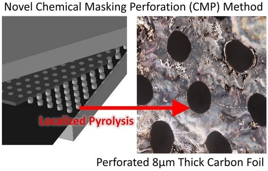
Novel Method of Carbon Precursor Masking to Generate Controlled Perforations in a Carbon Film

1
Chair of Plastics Technology, TU Dortmund University, Leonhard-Euler-Str. 5, 44227 Dortmund, Germany
2
Leibniz Institute of Polymer Research, Hohe Str. 6, 01069 Dresden, Germany
*
Author to whom correspondence should be addressed.
Macromol 2022, 2(4), 554-561; https://doi.org/10.3390/macromol2040036
Submission received: 14 November 2022 / Revised: 25 November 2022 / Accepted: 29 November 2022 / Published: 5 December 2022
(This article belongs to the Special Issue Functionalization of Polymers for Advanced Applications)

Abstract

:
A patterned carbon film was produced from Linear Low-Density Polyethylene (LLDPE) by the implementation of a novel method named Chemical Masking Perforation (CMP). The following paper describes this procedure, starting with the sulfonation of the precursor polymer LLDPE with Chlorosulphonic acid to stabilize the material, followed by Fourier-transform infrared spectroscopy (FTIR) evaluation to compare the atomic bonds from the stabilized film as well as from the masked sections of the film. To finalize, the cross-linked film was carbonized in an oven at 950 °C. The outcome of this process was a carbon film with a thickness similar to a carbon fiber diameter of 8 µm with controllable size and distribution.

Graphical Abstract

1. Introduction

Carbon films have several applications in many industries such as electronics, nuclear research, nano-devices, and electron microscopy [1,2,3,4,5,6,7,8]. Laser perforation, surface etching, and mechanical stamping are methods developed to generate functional perforation geometries through carbon films [9]. This paper presented a novel method for the perforation and topological patterning of carbon-based material. The resultant perforated carbon films can be used to construct biomimetic platelet matrix composites similar to the structures described in the work of Sakhavand et al. [10,11] and Rouhana and Stommel [12], and structures investigated by Behr et al. [13,14] and Mirkhalaf et al. [15]. Generating periodic porosity in brittle material also allows crack arresting and improves toughness [16,17,18]. Such structures show high toughness properties compared with bulk ceramics and stiffness and strength properties that can be tailored to an intended application. Generating perforated carbon films with an energy-efficient and accurate method could allow the construction of carbon platelet composites and carbon film laminates with varying properties and applications. Successful manufacturing of patterned carbon foils as described by Rouhana and Stommel [12] would allow the design of novel composites with potentially similar mechanical properties as carbon fiber composites.
Other properties can also be exploited, such as thermal and electrical conductivity, as explained in the paper of Choi et al. [19], where organic photovoltaic cells were fabricated from carbon nanosheets with PE as the precursor material, reaching conductivity values of 1100 S/cm. Meanwhile, thermal properties can also be enhanced in composite materials using carbon fibers, leading to better thermal conductivity that can be achieved when the fibers have an optimal orientation within the matrix [20]. This can be mitigated by implementing carbon films, which can be better aligned and have a higher-conductivity flat surface.
For the manufacturing of high-strength carbon structures, different precursor materials can be used, such as PAN (Polyacrylonitrile), Pitch, Polyolefin, Lignin, and others [21,22]. Those precursor materials are generally shaped in the required form as fiber by spinning methods or films by known extrusion methods [23,24]. After obtaining the desired geometries, the material proceeds through a stabilization step which alters the molecular structure of the material to avoid pyrolysis in the carbonization oven. Instead, it carbonizes by maintaining the carbon-carbon bonds and losing all other atoms in the molecular structure [25]. For example, in the process of carbon fiber production, a polymer such as PAN is chemically stabilized with oxygen at 350 °C before carbonization at a minimum of 950 °C in a chemically inert environment [26].
Chemical masking combined with etching is used to eliminate the unmasked zone in patterning methods [6]. The novel method described in this article eliminates, by pyrolysis, the masked zone, as the chemical stabilization of the polymer is not allowed. In other words, the polymer-selective crosslinking induces carbonization in stabilized unmasked zones and pyrolysis in masked zones.

2. Materials and Methods

2.1. Sulfornation

LLDPE (Long-chain Low-Density Polyethylene) was selected as a precursor as it is available in film form with 27 µm thickness or thinner and can be stabilized using a high concentration Sulfuric of Chlorosulphonic acids [27]. The LLDPE film used had a crystallinity of 40–50% and was purchased from Carl Roth [28]. Chlorosulphonic acid with a concentration of 99% [29] was selected for stabilization as it can be used at room temperature, in contrast to sulfuric acid, which requires heating to 140 °C to properly stabilize the LLDPE polymer [25,27,30,31]. Polytetrafluoroethylene (PTFE) is used as a masking material due to its high resistance to the used acid.
Two plates of PTFE were machined with the intended patterning geometry, which consists of small pillars with circular tops arranged in an equilateral array, as seen in Figure 1. This geometrical distribution is based on the work of Gordon et al. [32] and Jones and Gordon [33], resulting in an isotropic structure and relatively high toughness for a brittle material. The clamps were used to cover the film from both sides in the disk areas using additional pressure to prohibit the acid from reaching the masked areas, as shown in Figure 1. The figure shows the polymer film in black color with pins under it and above it that are aligned to cover the same circular patch from both sides. Surrounding the pins in a dark gray color is the acid, which works as the cross-linking activator.
Additional perforation geometries can also be produced by changing the PTFE clamp pattern, as shown in Figure 2. This geometry is inspired by bio-based Nacre material, with hierarchical high-stiffness hexagonal plates bonded by a high-plasticity matrix, resulting in a high-stiffness composite [12]. The acid is added between the clamps at room temperature and left for twelve to twenty-four hours depending on the film thickness so that the polymer film crosslinks in unmasked areas. The acid has a penetration depth of 30 µm [34], and thus it can stabilize the total thickness of the LLDPE film.
The stabilized film was evaluated with FTIR measurement to assess the quality of the stabilization and the masking. This measurement method can evaluate the chemical composition of a material by measuring the vibration frequency of the atomic bonds. Many atomic bonds, especially carbon-hydrogen bonds, have a signature resonance frequency [22]. By measuring those frequencies, it is possible to identify the dominant atom bonds. The measurement results are later shown in Figures 5 and 6.

2.2. Carbonization

The obtained film was later washed with distilled water and carbonized in an inert argon gas environment with a heating ramp of 16 °C per minute to reach 950 °C and remain at peak temperature for five minutes. It is essential to mention that further experiments were also conducted using nitrogen gas as an inert environment for the oven. The sample was then cooled at a similar rate until reaching room temperature. The film was supported by a thin-gauge stainless steel mesh without any restriction of shrinkage. Applying tension load or restricting the shrinkage of the material during carbonization allows better alignment of the carbon chains and improves the mechanical properties of the final carbon material [21].

3. Results

The obtained result after the sulfonation was a black LLDPE film with transparent dots, as seen in Figure 3. The more LLDPE shifted in color from transparent to black, the more it crosslinked.
Under the masked area, the acid penetrated a certain depth in the plane of the film. The results showed this “Transition Zone” at the edge of the masked area in the order of 20 µm, as shown in Figure 4. This transition thickness would be a reference for patterning geometry scale and tolerances as it determines what would be the smallest zone that the acid cannot laterally reach under the masking pins and the smallest geometry features possible to produce with this method of masking-induced perforation.
As LLDPE molecules mainly consist of carbon-hydrogen bonds, the areas where the acid reacted are expected to have less C–H stretching and H–C–H bending transmittance [21,30]. The FTIR measurement in Figure 5 showed the expected values with signature band zone 2840–2950 cm−1, which represents –CH2 stretching. Additionally, the 1440–1465 cm−1 zone is also significant, which represents –CH2 bending as shown in Figure 6. For crosslinked material, the transmittance was reduced significantly relative to the regular material and the masked areas maintained considerable transmittance, indicating less crosslinking and limited acid reaction.
The polymer film, which had an original thickness of 27 µm, was converted to a carbon film of 8 µm thickness, thus shrinking by ~70% in thickness. The circular patterns generated by masking had a diameter of 1.5 mm and, after carbonization, were reduced to an average diameter of 0.8 mm, representing a shrinkage of ~47% in the plane of the film. The final carbon film is shown in Figure 7 with traces of impurities resulting from the chemical process. Here, the edge of the perforated hole can also be seen as a smooth geometry without cracks or imperfections that could be achieved with this method, decreasing the possibility of crack propagation.

4. Conclusions

An accurate method to produce patterned carbon films could be achieved by the implementation of the Chemical Masking Perforation. Based on the FTIR analysis, the polyethylene film was successfully stabilized with chlorosulphonic acid at room temperature in the unmasked sections with nearly 20 µm of acid penetration into the masked sections. Regardless, once the stabilized film went through the carbonization in the oven, an accurate holey pattern throughout the film was formed by the pyrolysis of masked zones.
It is important to recall that this method is not limited to just one pattern throughout the whole film. As shown in this paper, CMP can be used to produce other perforation patterns depending on the design of the masking clamps. Other geometries can include tensile specimens for strengths analysis of the carbon foil, hexagonal pattern perforation resulting in connected hexagonal tablets, or others. This method offers a new technology for carbon film design and manufacturing that can offer enhanced mechanical, thermal, and electrical properties for different applications. Our motivation was to produce carbon foils comparable to carbon fibers used in structural composite applications; this method shows that the manufacturing of such foils is possible after further improvement of the process.

Author Contributions

Conceptualization, R.R.; methodology, R.R.; software, M.S. (Markus Stommel); validation, M.S. (Michael Stanko), M.M. and M.S. (Markus Stommel); formal analysis, R.R.; investigation, R.R.; resources, M.S. (Markus Stommel); writing—original draft preparation, R.R.; writing—review and editing, R.R.; visualization, R.R.; supervision, M.S. (Markus Stommel); project administration, M.S. (Michael Stanko); funding acquisition, M.S. (Markus Stommel). All authors have read and agreed to the published version of the manuscript.

Funding

This research received no external funding.

Institutional Review Board Statement

Not applicable.

Informed Consent Statement

Not applicable.

Data Availability Statement

The data presented in this study are available on request from the corresponding author.

Conflicts of Interest

The authors declare no conflict of interest.

References

  1. Roch, T.; Beyer, E.; Lasagni, A. Surface modification of thin tetrahedral amorphous carbon films by means of UV direct laser interference patterning. Diam. Relat. Mater. 2010, 19, 1472–1477. [Google Scholar] [CrossRef]
  2. Lünsdorf, H.; Spiess, E. A rapid method of preparing perforated supporting foils for the thin carbon films used in high resolution transmission electron microscopy. J. Microsc. 1986, 144, 211–213. [Google Scholar] [CrossRef]
  3. Lei, Y.; Yang, S.; Wu, M.; Wilde, G. Surface patterning using templates: Concept, properties and device applications. Chem. Soc. Rev. 2011, 40, 1247–1258. [Google Scholar] [CrossRef] [PubMed]
  4. Kim, B.S.; Park, J.H.; Hong, N.; Bae, J.; Yang, C.-S.; Shin, K. Ultrathin carbon film from carbonization of spin-cast polyacrylonitrile film. J. Ind. Eng. Chem. 2013, 19, 1631–1637. [Google Scholar] [CrossRef]
  5. Hasebe, H.; Okuno, H.; Kuboki, H.; Ryuto, H.; Fukunishi, N.; Kamigaito, O.; Goto, A.; Kase, M.; Yano, Y. Development of long-life carbon stripper foils for uranium ion beams. Nucl. Instrum. Methods Phys. Res. Sect. A Accel. Spectrom. Detect. Assoc. Equip. 2010, 613, 453–456. [Google Scholar] [CrossRef]
  6. Wei, L.; Nitta, N.; Yushin, G. Lithographically patterned thin activated carbon films as a new technology platform for on-chip devices. ACS Nano 2013, 7, 6498–6506. [Google Scholar] [CrossRef]
  7. Schueller, O.J.A.; Brittain, S.T.; Whitesides, G.M. Fabrication of glassy carbon microstructures by pyrolysis of microfabricated polymeric precursors. Adv. Mater. 1997, 9, 477–480. [Google Scholar] [CrossRef]
  8. Schueller, O.J.; Brittain, S.T.; Whitesides, G.M. Fabrication of glassy carbon microstructures by soft lithography. Sens. Actuators A Phys. 1999, 72, 125–139. [Google Scholar] [CrossRef]
  9. Fuchs, A.N.; Schoeberl, M.; Tremmer, J.; Zaeh, M.F. Laser Cutting of Carbon Fiber Fabrics. Phys. Procedia 2013, 41, 372–380. [Google Scholar] [CrossRef] [Green Version]
  10. Sakhavand, N. Mechanics of Platelet-Matrix Composites across Scales: Theory, Multiscale Modeling, and 3D Fabrication. Ph.D. Dissertation, Rice University, Houston, TX, USA, 2015. [Google Scholar]
  11. Sakhavand, N.; Shahsavari, R. Universal composition-structure-property maps for natural and biomimetic platelet-matrix composites and stacked heterostructures. Nat. Commun. 2015, 6, 6523. [Google Scholar] [CrossRef]
  12. Rouhana, R.; Stommel, M. Modelling and Experimental Investigation of Hexagonal Nacre-Like Structure Stiffness. J. Compos. Sci. 2020, 4, 91. [Google Scholar] [CrossRef]
  13. Behr, S.; Köllner, A.; Schneider, G.A. Tailoring Toughness and Mechanical Reliability by Controlled Defects: Nature-Inspired Composite Laminates of Laser-Perforated Yttria-Stabilized Zirconia. Adv. Eng. Mater. 2016, 18, 1877–1883. [Google Scholar] [CrossRef]
  14. Behr, S.; Vainio, U.; Müller, M.; Schreyer, A.; Schneider, G.A. Large-scale parallel alignment of platelet-shaped particles through gravitational sedimentation. Sci. Rep. 2015, 5, 9984. [Google Scholar] [CrossRef] [Green Version]
  15. Mirkhalaf, M.; Dastjerdi, A.K.; Barthelat, F. Overcoming the brittleness of glass through bio-inspiration and micro-architecture. Nat. Commun. 2014, 5, 3166. [Google Scholar] [CrossRef] [Green Version]
  16. Lipperman, F.; Ryvkin, M.; Fuchs, M.B. Crack arresting low-density porous materials with periodic microstructure. Int. J. Eng. Sci. 2008, 46, 572–584. [Google Scholar] [CrossRef]
  17. Marshall, A.L.; Karandikar, P.G.; Givens, B.P.; Liszkiewicz, A.F.; Segura, R.; Klier, E.M.; Doherty, K.J. Geometrical Effect on Damage in Reaction Bonded Ceramic Composites having Experienced High Strain Rate Impact. Ceram. Eng. Sci. Proc. 2014, 41–52. [Google Scholar] [CrossRef]
  18. Chan, K.S.; He, M.Y.; Hutchinson, J.W. Cracking and stress redistribution in ceramic layered composites. Mater. Sci. Eng. A 1993, 167, 57–64. [Google Scholar] [CrossRef]
  19. Choi, D.; Yeo, J.-S.; Joh, H.-I.; Lee, S. Carbon Nanosheet from Polyethylene Thin Film as a Transparent Conducting Film: “Upcycling” of Waste to Organic Photovoltaics Application. ACS Sustain. Chem. Eng. 2018, 6, 12463–12470. [Google Scholar] [CrossRef]
  20. Ali, Z.; Gao, Y.; Tang, B.; Wu, X.; Wang, Y.; Li, M.; Hou, X.; Li, L.; Jiang, N.; Yu, J. Preparation, Properties and Mechanisms of Carbon Fiber/Polymer Composites for Thermal Management Applications. Polymers 2021, 13, 169. [Google Scholar] [CrossRef] [PubMed]
  21. Kim, J.W.; Lee, J.S. Preparation of carbon fibers from linear low density polyethylene. Carbon 2015, 94, 524–530. [Google Scholar] [CrossRef]
  22. Kim, K.-W.; Lee, H.-M.; An, J.-H.; Kim, B.-S.; Min, B.-G.; Kang, S.-J.; An, K.-H.; Kim, B.-J. Effects of cross-linking methods for polyethylene-based carbon fibers: Review. Carbon Lett. 2015, 16, 147–170. [Google Scholar] [CrossRef] [Green Version]
  23. Morris, E.A.; Weisenberger, M.C.; Bradley, S.B.; Abdallah, M.G.; Mecham, S.J.; Pisipati, P.; McGrath, J.E. Synthesis, spinning, and properties of very high molecular weight poly(acrylonitrile-co-methyl acrylate) for high performance precursors for carbon fiber. Polymer 2014, 55, 6471–6482. [Google Scholar] [CrossRef] [Green Version]
  24. Ball, L.E. Process for Preparing Biaxially Oriented Acrylonitrile Polymer Film. U.S. Patent US3418406, 24 December 1968. [Google Scholar]
  25. Karacan, I.; Benli, H. Use of sulfonation procedure for the development of thermally stabilized isotactic polypropylene fibers prior to carbonization. J. Appl. Polym. Sci. 2012, 123, 234–245. [Google Scholar] [CrossRef]
  26. Singh Gill, A.; Visotsky, D.; Mears, L.; Summers, J.D. Cost Estimation Model for Polyacrylonitrile-Based Carbon Fiber Manufacturing Process. J. Manuf. Sci. Eng. 2017, 139, 268. [Google Scholar] [CrossRef]
  27. Pereña, J.; Lorenzo, V.; Zamfirova, G.; Dimitrova, A. Microhardness of polyethylene surface modified by chlorosulphonic acid. Polym. Test. 2000, 19, 231–236. [Google Scholar] [CrossRef]
  28. Carl Roth GmbH + Co. KG. Clear Cling Film LLDPE. 2022. Available online: https://www.carlroth.com (accessed on 5 August 2022).
  29. Sigma-Aldrich Chemie GmbH. Chlorosulphonic Acid 571024-1KG. 2022. Available online: https://www.sigmaaldrich.com (accessed on 13 October 2022).
  30. Postema, A.R.; de Groot, H.; Pennings, A.J. Amorphous carbon fibres from linear low density polyethylene. J. Mater. Sci. 1990, 25, 4216–4222. [Google Scholar] [CrossRef]
  31. Palmenaer, A.; Wortberg, G.; Drissen, F.; Seide, G.; Gries, T. Production of Polyethylene Based Carbon Fibres. Chem. Eng. Trans. 2015, 1699–1704. [Google Scholar] [CrossRef]
  32. Gordon, J.L.; Jones, D.P.; Banas, D.; Hutula, D.N. A Collapse Surface for a Perforated Plate With an Equilateral Triangular Array of Penetrations. J. Press. Vessel Technol. 2002, 124, 201–206. [Google Scholar] [CrossRef]
  33. Jones, D.P.; Gordon, J.L. Elasto-Plastic Analysis of Perforated Plates Containing Triangular Penetration Patterns of 10 Percent Ligament Efficiency. J. Press. Vessel Technol. 1979, 101, 210–215. [Google Scholar] [CrossRef]
  34. Penning, J.P.; Lagcher, R.; Pennings, A.J. The effect of diameter on the mechanical properties of amorphous carbon fibres from linear low density polyethylene. Polym. Bull. 1991, 25, 405–412. [Google Scholar] [CrossRef]
Figure 1. Photograph of the PTFE machined clamp: setup for masked stabilization and complete view of the pins and fluid channels.
Macromol 02 00036 g001
Figure 2. Optical microscope image of crosslinked LLDPE with nacre pattern geometry.
Macromol 02 00036 g002
Figure 3. Optical microscope image of crosslinked LLDPE film with transparent non-stabilized (white) zones.
Macromol 02 00036 g003
Figure 4. Optical microscope image of the stabilization “Transition Zone”.
Macromol 02 00036 g004
Figure 5. FTIR comparing regular LLDPE film and masked and stabilized film in a 2800 cm−1 to 2950 cm−1 range.
Macromol 02 00036 g005
Figure 6. FTIR comparing regular LLDPE film and masked and stabilized film in a 1400 cm−1 to 1500 cm−1 range.
Macromol 02 00036 g006
Figure 7. Optical microscope image of the carbonized film.
Macromol 02 00036 g007
Publisher’s Note: MDPI stays neutral with regard to jurisdictional claims in published maps and institutional affiliations.

