
Thermoelectric Power Generators: State-of-the-Art, Heat Recovery Method, and Challenges


Abstract
:1. Introduction
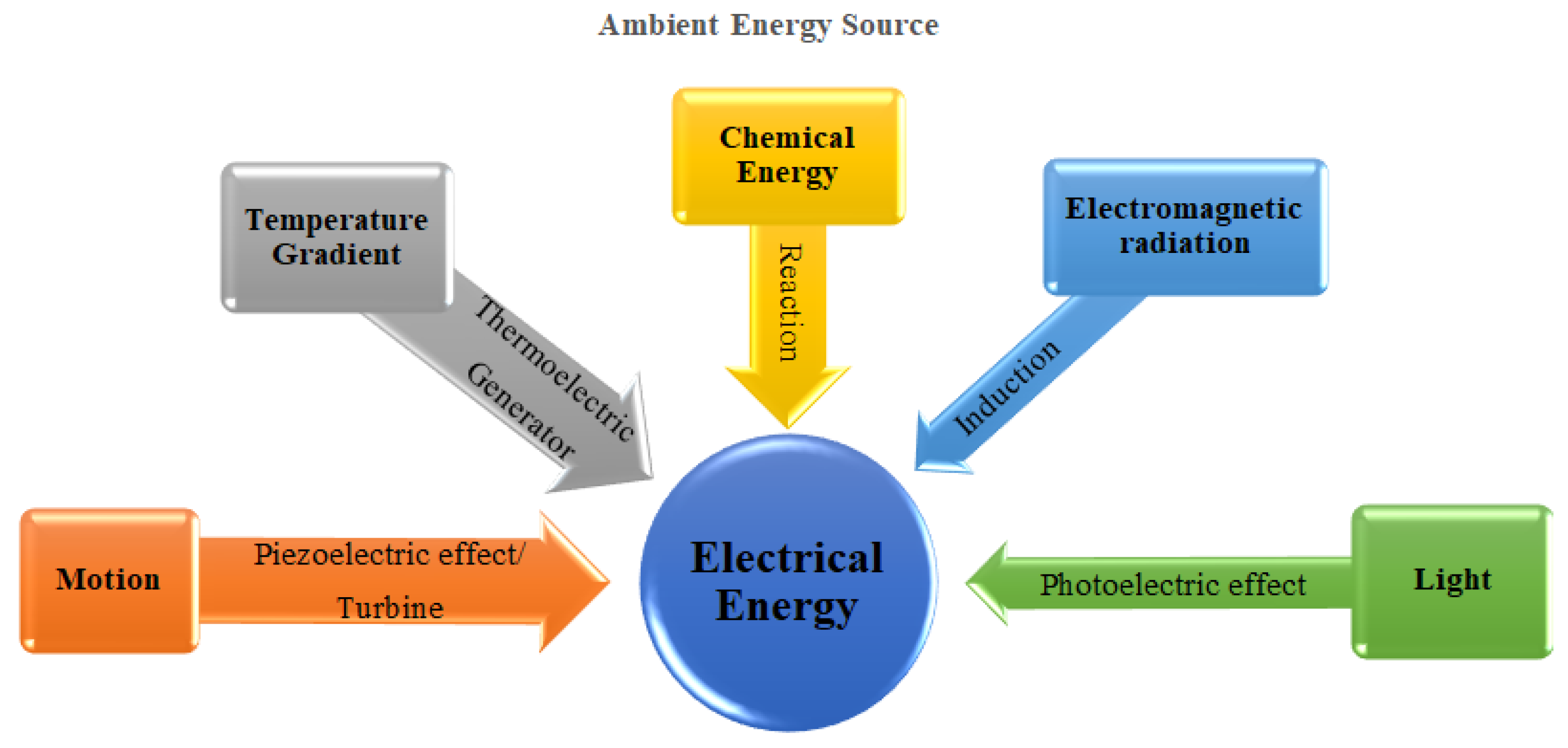
- Natural energy comprises several sources of energy that can be transformed into electricity, as presented in Figure 1. For instance, wind, hydro energy, waves, and mechanical vibration [6,7] create motion that can be converted into electrical energy using the piezoelectric effect or turbines. Similarly, the temperature gradient, chemical energy, electromagnetic radiation, and light are forms of green energy that can be used to generate electricity via thermoelectric generators (TEGs), and the reaction, induction, and photoelectric effects, respectively. Renewable energy sources constitute 25% of the power generation sector, and this proportion is expected to increase to 85% by 2050 [8];
- Energy recovery resources comprise waste energy, in the form of kinetic energy or heat from applications, that is recovered and reused. The related approaches include flue gas heat recovery, the recovery of kinetic energy using a flywheel, and hybrid pneumatic power systems. Thus, the main advantage of these systems is the recovery of waste energy that would otherwise be lost.
Scope of the Paper
- Presenting the history of main milestones that TEG passes through since its first invention;
- Displaying the applications of thermoelectric (TE) in the past, starting from 1985, and the expectations of TE applications for the foreseeable future, specifically 2030;
- Reviewing over 180 papers and classifying them into specific categories;
- Demonstrating the challenges that the researchers have faced during the study. This section is crucial as it is noticed that the progress of TEG development was by working on solving the challenges of the previous studies.
2. Theoretical Background
2.1. Seebeck Effect
2.2. Peltier Effect
2.3. Thomson Effect
2.4. Thermoelectric Generators Working Process

2.5. Figure of Merit (ZT)
3. Historical Notes
4. TEG in Applications and Classifications
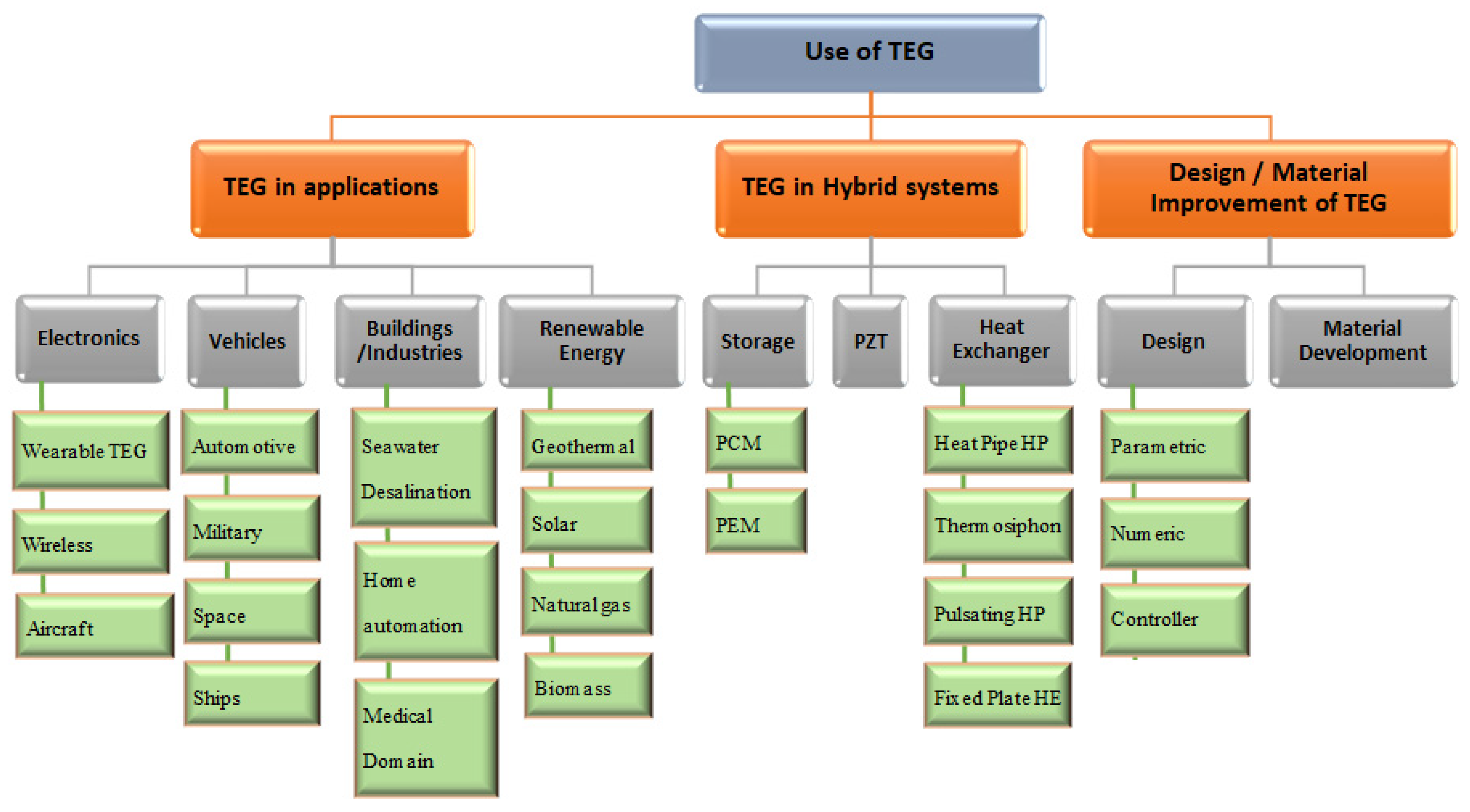
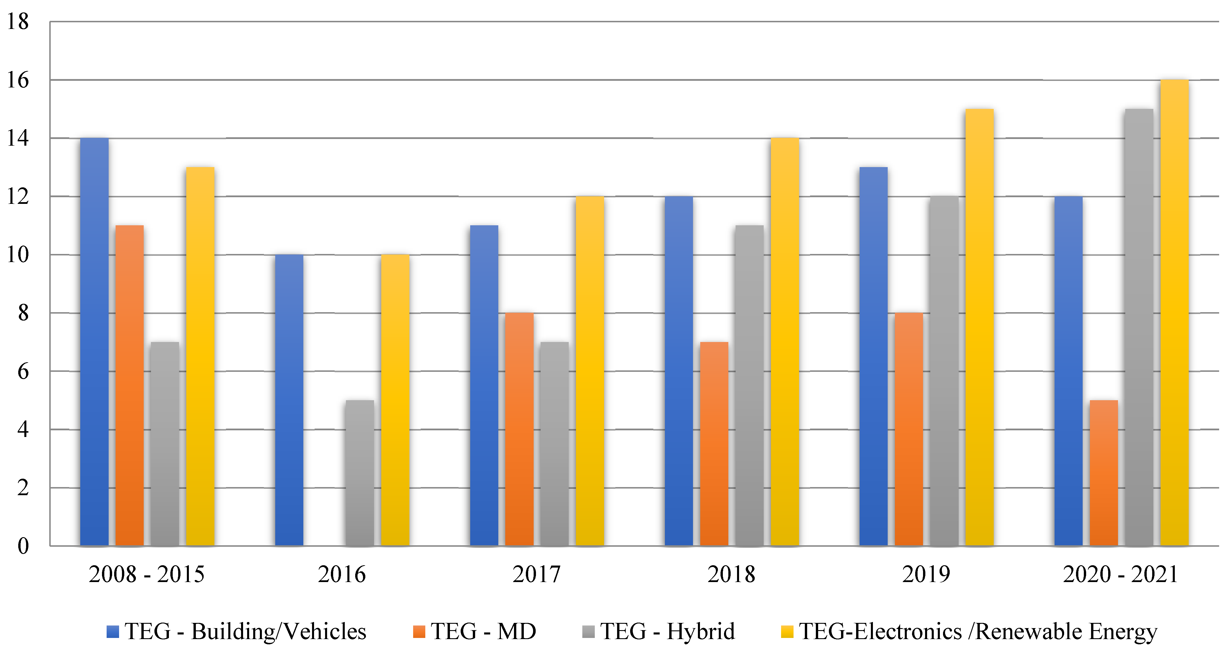
- TEG in applications: TEG has been publicized widely and rapidly in various fields, electronics, vehicles, industries, and renewable energy;
- TEG in hybrid systems: according to the studied papers, TEG has a considerable share when involved with other energy recovery systems such as storage, piezoelectric, and heat exchangers;
- Design and material improvement: research has also discussed the design and material development to reach an optimum output of a TEG unit.
4.1. TEG in Heat Recovery Systems
4.2. TEG in Hybrid Heat Recovery Systems
5. TEG New Technologies in Applications and Challenges
5.1. Materials Properties
5.2. New Technologies and Applications
5.3. Challenges
5.4. Proposed Solution to Some of the Challenges
6. Conclusions
- The distinctive nature of using TEG that provides electricity with a gradient temperature even at a low scale and over a wide temperature range, scalability, quietness, ecofriendliness, reliability, absence of moving parts, and maintenance-free, has made TEGs a primary solution to specific energy problems concerning power generation and recovering heat in a stationary and environmentally friendly approach;
- The small efficiency of TEG has limited its growth in some applications. The use of TE in several regions has conquered significant accomplishments in some applications and overall disappointment in others;
- TEG combined with HEs is an up-and-coming technology, where HEs transfer the heat to the TEG, which helps create better circumstances to higher gradient temperature and, consequently, higher power output, which was illustrated in various studies;
- For waste heat recovery applications, TEGs are very promising as well because the heat is free and lost unless it is captured by a heat recovery method. However, the payback period may be longer or shorter according to the gradient temperature and TEG efficiency. Consequently, the research is converged on enhancing the efficiency of TE materials and studying new strategies of TEGs that provide superior incorporation of energy conversion systems;
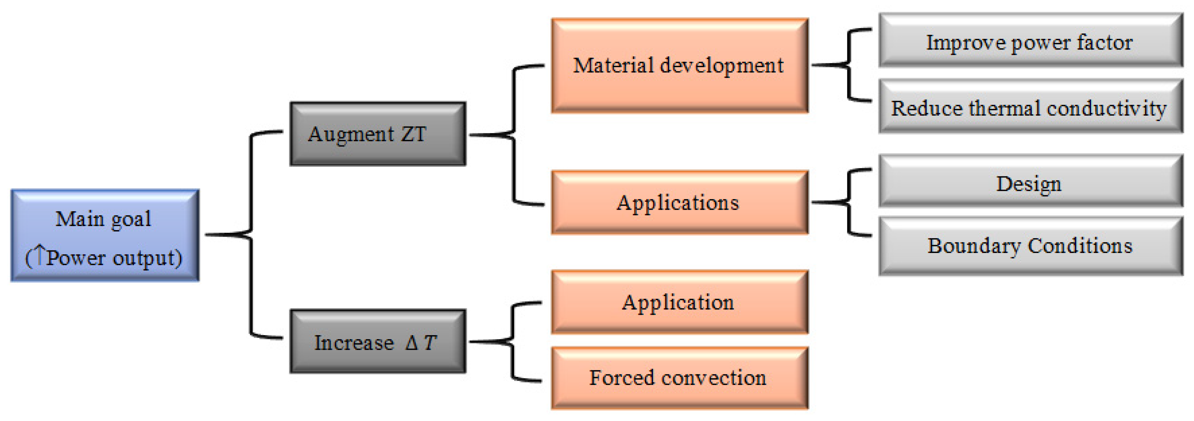
- To increase the power output, TEG should under either one or both of the steps: increase ZT or gradient temperature, as shown in Figure 16. In some cases, the temperature cannot exceed a specific range to protect the TEG material. Thus, results show that combining TEG with other heat recovery methods, such as heat pipes, PCM, and PEM has augmented the desirable output, where the combined system increases the power output and protects the TEG from overheating. Hence, it is recommended to do further studies on TEG combined with other heat recovery methods;
- Forced convection enhances heat transfer, and consequently increases gradient temperature. However, it requires additional power. Thus, vortex generators are recommended to enhance heat transfer. Intensive research on micro TEG opened the opportunity to improve TEG in wearable devices, sensors, power electronics, where there are accumulative efforts to make micro TEG a substitute for the traditional batteries;
- Throughout the research, there is an accumulative effort to develop new materials diminish cost, and build an eco-friendly system. Even though TEGs have a high initial cost, in the long term, TEGs may repay the initial cost and become a profit-free energy source;
- The efficiency of TEG has been developed over the years due to design and materials improvement. However, with all the improvements on TEGs materials, most of the papers recommended further researches to solve the foremost challenge in TE technology, which is enhancing and designing innovative TE materials with proper values of the figure of merit and power factor. Hence, research on improving or developing new thermoelectric materials has no end;
- Constructing a TEG with theoretical efficiency is an enormous progress that the research is working on, especially with the various concrete challenges. Thus, the growth of TE materials requires continuous efforts by material scientists, physicists, chemists, and theory scientists.
Author Contributions
Funding
Institutional Review Board Statement
Informed Consent Statement
Data Availability Statement
Conflicts of Interest
Nomenclature
| BCs | Boundary conditions |
| CPV | Concentric photovoltaic |
| ERU | Energy recovering units |
| HHRS | Hybrid heat recovery system |
| HP | Heat pipe |
| HPHE | Heat pipe heat exchanger |
| HRS | Heat recovery system |
| PCM | Phase change material |
| PEM | Proton exchange membrane |
| PV | Photovoltaic |
| PZT | Piezoelectric |
| RES | Renewable energy system |
| TE | Thermoelectric |
| TEC | Thermoelectric cooler |
| TEG | Thermoelectric generator |
| TED | Thermoelectric device |
| THE | Thermosiphon |
| WHR | Waste heat recovery |
References
- Andreas, S.; Paula, F. Electricity: A New Open Access Journal. Electricity 2020, 1, 60–61. [Google Scholar]
- Ciontea, C.; Iov, F. A Study of Load Imbalance Influence on Power Quality Assessment for Distribution Networks. Electricity 2021, 2, 77–90. [Google Scholar] [CrossRef]
- Andrea, T.; Lidia, P.V.; Marco, B.; Giorgio, B. Assessing the Impact on Grid Infrastructure of Electrification Pathways for the Italian Residential Sector. Electricity 2021, 2, 48–62. [Google Scholar]
- Ioannis, K.; Bazionis, P.; Georgilakis, S. Review of Deterministic and Probabilistic Wind Power Forecasting: Models, Methods, and Future Research. Electricity 2021, 2, 13–47. [Google Scholar]
- Nikhil, K.; Jorrit, B.; Jose, R.T.; van der Meijden, M.; Palensky, P. A Fundamental Study on the Transient Stability of Power Systems with High Shares of Solar PV Plants. Electricity 2020, 1, 62–86. [Google Scholar]
- Yildiz, F. Potential Ambient Energy-Harvesting Sources and Techniques. J. Technol. Stud. 2009, 35, 40–48. [Google Scholar] [CrossRef]
- Khatun Mishu, M.; Rokonuzzaman, M.; Pasupuleti, J. Prospective Efficient Ambient Energy Harvesting Sources for IoT-Equipped Sensor Applications. Electronics 2020, 9, 1345. [Google Scholar] [CrossRef]
- Gielena, D.; Boshell, F.; Saygin, D.; Bazilian, M.D.; Wagner, N.; Gorini, R. The role of renewable energy in the global energy transformation. Energy Strategy Rev. 2019, 24, 38–50. [Google Scholar] [CrossRef]
- Mukhopadhyay, R.; Karisiddaiah, S.M.; Mukhopadhyay, J. Scientific Assessment. In Climate Change: Alternate Governance Policy for South Asia; Elsevier: Amsterdam, The Netherlands, 2018; pp. 15–53. [Google Scholar]
- Mukhopadhyay, R.; Karisiddaiah, S.M.; Mukhopadhyay, J. Threat to Opportunity. In Climate Change: Alternate Governance Policy for South Asia; Elsevier: Amsterdam, The Netherlands, 2018; pp. 99–117. [Google Scholar]
- Maradin, D. Advantages and Disadvantages of Renewable Energy Sources Utilization. Int. J. Energy Econ. Policy 2021, 11, 2146–4553. [Google Scholar] [CrossRef]
- Juanicó, L.E. World Energy Saving from Cars: An Innovative and Feasible Proposal. Int. Sch. Res. Not. 2011, 2011, 5. [Google Scholar] [CrossRef] [Green Version]
- Yu, M.G.; Nam, Y. Feasibility Assessment of Using Power Plant Waste Heat in Large Scale Horticulture Facility Energy Supply Systems. Energies 2016, 9, 112. [Google Scholar] [CrossRef] [Green Version]
- Shareef, M.H.; Sajid, A.; Majeed, A.A.; Adnan, M.A.B. Efficiency Calculation of a Thermoelectric Generator. Int. J. Sci. Res. 2015, 5, 2319–7064. [Google Scholar]
- Chen, J.; Li, K.; Liu, C.; Li, M.; Lv, Y.; Jia, L.; Jiang, S. Enhanced Efficiency of Thermoelectric Generator by Optimizing Mechanical and Electrical Structures. Energies 2017, 10, 1329. [Google Scholar] [CrossRef] [Green Version]
- Snyder, J.; Eric, G.; Toberer, S. Complex Thermoelectric Materials. Nat. Mater. 2010, 7, 105–114. [Google Scholar] [CrossRef] [PubMed]
- Karri, M.A. Thermoelectric Power Generation System Optimization Studies; Clarkson University: New York, NY, USA, 2011. [Google Scholar]
- Zoui, M.A.; Bentouba, S.; Stocholm, J.G.; Bourouis, M. A Review on Thermoelectric Generators: Progress and Applications. Energies 2020, 13, 3606. [Google Scholar] [CrossRef]
- Kumar, P.M.; Babu, V.J.; Subramanian, A.; Bandla, A.; Thakor, N.; Ramakrishna, S.; Wei, H. The Design of a Thermoelectric Generator and Its Medical Applications. Designs 2019, 3, 22. [Google Scholar] [CrossRef] [Green Version]
- Indira, S.S.; Vaithilingam, C.A.; Chong, K.-K.; Saidur, R.; Faizal, M.; Abubakar, S.; Paiman, S. A review on various configurations of hybrid concentrator photovoltaic and thermoelectric generator system. Sol. Energy 2021, 201, 122–148. [Google Scholar] [CrossRef]
- Patidar, S. Applications of Thermoelectric Energy: A review. Int. J. Res. Appl. Sci. Eng. Technol. 2018, 6, 2321–9653. [Google Scholar] [CrossRef]
- Zimbovskaya, N.A. Seebeck effect in molecular junctions. J. Phys. Condens. Matter 2016, 28, 183002. [Google Scholar] [CrossRef]
- Mukda, T.; Jantaratana, P. Peltier Effect Based Temperature Controlled System for Dielectric Spectroscopy. J. Phys. Conf. Ser. 2017, 901, 12059. [Google Scholar] [CrossRef] [Green Version]
- Zhang, M.; Tian, Y.; Xie, H.; Wu, Z.; Wang, Y. Influence of Thomson effect on the thermoelectric generator. Int. J. Heat Mass Transf. 2019, 137, 1183–1190. [Google Scholar] [CrossRef]
- Benziger, B.; Anu Nair, P.; Balakrishnan, P. Review Paper On Thermoelectric Air-Conditioner Using Peltier Modules. Int. J. Mech. Eng. 2015, 4, 49–56. [Google Scholar]
- Igor Lashkevych, J.E.; Velázquez, O.Y.; Yuri, T.; Gurevich, G. Special Important Aspects of the Thomson Effect. J. Electron. Mater. 2018, 47, 3189–3192. [Google Scholar] [CrossRef]
- Velmre, E. Thomas Johann Seebeck (1770–1831). Proc. Est. Acad. Sci. Eng. 2007, 13, 276–282. [Google Scholar]
- Messler, R.W., Jr. Chapter 9: The Essence of Materials for Engineers. In Assembly Automation; Jones and Bartlet Learning: Burlington, MA, USA, 2011; pp. 243–274. [Google Scholar]
- Bogala, M.R.; Reddy, R.G. Reaction kinetic studies of metal-doped magnesium silicides. J. Mater. Sci. 2017, 52, 11962–11976. [Google Scholar] [CrossRef]
- Duckworth, H.E. Electricity and Magnetism; Holt Rinehart and Winston: New York, NY, USA, 1960; pp. 180–181. [Google Scholar]
- Kinsella, C.E.; O’Shaughnessy, S.M.; Deasy, M.J.; Duffy, M.; Robinson, A.J. Battery Charging Considerations in Small Scale Electricity Generation from a Thermoelectric Module. Appl. Energy 2014, 114, 80–90. [Google Scholar] [CrossRef]
- Mahan, G.D. Introduction to thermoelectrics. APL Mater. 2016, 4, 104806. [Google Scholar] [CrossRef]
- Zhang, C.-W.; Xu, K.-J.; Li, L.-Y.; Yang, M.-Z.; Gao, H.-B.; Chen, S.-R. Study on a Battery Thermal Management System Based on a Thermoelectric Effect. Energies 2018, 11, 297. [Google Scholar]
- Pasquale, G.D. Energy harvesters for powering wireless systems. In Handbook of Mems for Wireless and Mobile Applications; Woodhead Publishing Series in Electronic and Optical Materials: Torino, Italy, 2013; pp. 345–400. [Google Scholar]
- Vaidya, M. Optimal Usage of Dissipated/Wasted Thermoelectric Energy (Including Human Heat) On a Small Scale through Harvesting. Int. J. Innov. Res. Sci. Eng. Technol. 2017, 6, 2347–6710. [Google Scholar]
- Jouhara, H.; Żabnieńska-Góra, A.; Khordehgah, N.; Doraghi, Q.; Les Norman, L.A.; Axcell, B.; Wrobel, L.; Dai, S. Thermoelectric generator (TEG) technologies and applications. Int. J. 2021, 9, 100063. [Google Scholar]
- Al-Habahbeh, O.M.; Mohammad, A.; Al-khalidi, A.; Khanfer, M.; Obeid, M. Design optimization of a large-scale thermoelectric generator. J. King Saud Univ. Eng. Sci. 2018, 30, 177–182. [Google Scholar] [CrossRef] [Green Version]
- Champier, D. Thermoelectric generators: A review of applications. Energy Convers. Manag. 2017, 140, 167–181. [Google Scholar] [CrossRef]
- Tzounis, L. Organic Thermoelectrics and Thermoelectric Generators; IntechOpen: London, UK, 2019. [Google Scholar]
- Tritt, T.M. Thermoelectric Materials: Principles, Structure, Properties, and Applications; Elsevier: Amsterdam, The Netherlands, 2002. [Google Scholar]
- Kuphaldt, T.R. Electrons and “holes”. In Semiconductors: Solid-State Device Theory; Prentice-Hall: Hoboken, NJ, USA, 2001. [Google Scholar]
- Prunet, G.; Pawula, F.; Fleury, G.; Cloutet, E.; Robinson, A.J.; Hadziioannou, G.; Pakdel, A. A Review on Conductive Polymers and Their Hybrids for Flexible and Wearable Thermoelectric Applications. Mater. Today Phys. 2021, 18, 100402. [Google Scholar] [CrossRef]
- Zhu, W.; Deng, Y.; Gao, M.; Wang, Y.; Cui, J.; Gao, H. Thin-film solar thermoelectric generator with enhanced power output: Integrated optimization design to obtain directional heat flow. Energy 2015, 89, 106–117. [Google Scholar] [CrossRef]
- Kanimba, E.; Tian, Z. Modeling of a Thermoelectric Generator Device: A Look at Trends in the Technology. In Thermoelectrics for Power Generation—A Look at Trends in the Technology; IntechOpen: London, UK, 2016; pp. 461–479. [Google Scholar]
- Meng, F.; Chen, L.; Sun, F. Performance analysis for two-stage TEC system driven by two-stage TEG obeying Newton’s heat transfer law. Math. Comput. Model. 2010, 52, 586–595. [Google Scholar] [CrossRef]
- Salim, A.T.A.; Prasety, Y.; Fakhrudin, Y.A. Study of Effect Comparison Thermoelectric Characteristics of TEC and TEG by Considering the Difference in Temperature and Variable Resistant. Int. Res. J. Adv. Eng. Sci. 2018, 3, 2455–9024. [Google Scholar]
- Srinivasan, B. Novel Chalcogenide Based Glasses, Ceramics & Polycrystalline Materials for Thermoelectric Application. Ph.D. Thesis, University of Rennes 1, Rennes, France, 2018. [Google Scholar]
- Luo, X.; Bob, C.; Chong-an Di, S.; Mei, J. Flexible and Printed Organic Thermoelectrics: Opportunities and Challenges. Available online: https://www.sigmaaldrich.com/FR/fr/technical-documents/technical-article/materials-science-and-engineering/organic-electronics/flexible-and-printed-organic-thermoelectrics (accessed on 20 June 2021).
- Twaha, S.; Zhu, J.; Yan, Y.; Li, B. A comprehensive review of thermoelectric technology: Materials, applications, modelling and performance improvement. Renew. Sustain. Energy Rev. 2016, 65, 698–726. [Google Scholar] [CrossRef]
- Twaha, S.; Zhu, J.; Maraaba, L.; Huang, K.; Li, B.; Yan, Y. Maximum Power Point Tracking Control of a Thermoelectric Generation System Using the Extremum Seeking Control Method. Energies 2017, 10, 2016. [Google Scholar] [CrossRef] [Green Version]
- Allon, I.H.; Chen, R.; Delgado, R.D.; Liang, W.; Erik, C.G.; Najarian, M.; Majumdar, A.; Yang, P. Enhanced Thermoelectric Performance of Rough Silicon Nanowires. Nature 2007, 451, 163–167. [Google Scholar]
- Polozine, A.; Sirotinskaya, S.; Schaeffer, L. History of Development of Thermoelectric Materials for Electric Power Generation and Criteria of their Quality. Mater. Res. 2014, 17, 1260–1267. [Google Scholar] [CrossRef] [Green Version]
- Zhang, X.; Zhao, L. Thermoelectric materials: Energy conversion between heat and electricity. J. Mater. 2015, 1, 92–105. [Google Scholar] [CrossRef] [Green Version]
- Adhikari, K.R. Thermocouple: Facts and Theories. Himal. Phys. 2017, 6, 10–14. [Google Scholar] [CrossRef] [Green Version]
- Goldsmid, H.J.; Sc, B.; Douglas, R.W. The use of semiconductors in thermoelectric refrigeration. Br. J. Appl. Phys. 1954, 5, 386–390. [Google Scholar] [CrossRef]
- Punith, N.; Swamy, G.M.; Yalagi, S. A Thermoelectric Generator Systems Forwaste Heat Recovery—A Review. Int. J. Eng. Res. Technol. 2015, 3, 1–10. [Google Scholar]
- Beretta, D.; Neophytou, N.; James, H.M.; Kanatzidis, M.G. Thermoelectrics: From history, a window to the future. Mater. Sci. Eng. R 2018, 138, 210–255. [Google Scholar] [CrossRef]
- Uemura, K.-i. History of Thermoelectricity Development in Japan. J. Thermoelectr. 2002, 3, 1–16. [Google Scholar]
- Zhang, Y.; Jaques, B.; Agarwal, V. Final Technical Report on Nanostructured Bulk Thermoelectric Generator for Efficient Power Harvesting for Self-Powered Sensor Network, Notre Dame; University of Notre Dame: Notre Dame, IN, USA, 2018. [Google Scholar]
- Forman, C.; Muritala, I.K.; Pardemann, R.; Meyer, B. Estimating the global waste heat potential. Renew. Sustain. Energy Rev. 2016, 57, 1568–1579. [Google Scholar] [CrossRef]
- Hendricks, T.; Choate, W.T. Engineering Scoping Study of Thermoelectric Generator Systems for Industrial Waste Heat Recovery; US Department of Energy Industrial Technologies Program: Washington, DC, USA, 2006; pp. 1–58.
- Glatz, W.; Muntwyler, S.; Hierold, C. Optimization and fabrication of thick flexible polymer based micro thermoelectric generator. Sens. Actuators A Phys. 2006, 132, 337–345. [Google Scholar] [CrossRef]
- Gou, X.; Xiao, H.; Yang, S. Modeling, experimental study and optimization on low-temperature waste heat thermoelectric generator system. Appl. Energy 2010, 87, 3131–3136. [Google Scholar] [CrossRef]
- Crane, D.T.; Jackson, G. Optimization of cross flow heat exchangers for thermoelectric waste heat recovery. Energy Convers. Manag. 2004, 45, 1565–1582. [Google Scholar] [CrossRef]
- Jaziri, N.; Boughamoura, A.; Müller, J.; Mezghani, B.; Tounsi, F.; Ismail, M. A comprehensive review of Thermoelectric Generators: Technologies and common applications. Energy Rep. 2020, 6, 264–287. [Google Scholar] [CrossRef]
- Shi, Y.; Wang, Y.; Deng, Y.; Gao, H.; Lin, Z.; Zhu, W.; Ye, H. A novel self-powered wireless temperature sensor based on thermoelectric generators. Energy Convers. Manag. 2014, 80, 110–116. [Google Scholar] [CrossRef]
- Patil, D.; Arakerimath, R.R.; Walke, P.V. Thermoelectric materials and heat exchangers for power generation—A review. Renew. Sustain. Energy Rev. 2018, 95, 1–22. [Google Scholar] [CrossRef]
- Chen, A.; Wright, P.K. Medical Applications of Thermoelectrics. In Modules, Systems, and Applications in Thermoelectrics; CRC Press: Boca Raton, FL, USA, 2012; pp. 1–17. [Google Scholar]
- Pennelli, G. Review of nanostructured devices for thermoelectric applications. Beilstein, J. Nanotechnol. 2014, 5, 1268–1284. [Google Scholar] [CrossRef] [Green Version]
- Blanc, S.L. Thermoelectric generators: Linking material properties and systems engineering for waste heat recovery applications. Sustain. Mater. Technol. 2014, 1, 26–35. [Google Scholar]
- Chen, T.; Zheng, Z.; Liang, G.; Fan, P. A New Design of a Thin-Film Thermoelectric Device. Nanomaterials 2020, 10, 990. [Google Scholar] [CrossRef]
- Korotkov, A.S.; Loboda, V.; Dzyubanenko, S.V.; Bakulin, E.M. Design of a Thin-Film Thermoelectric Generator for Low-Power Applications. Russ. Microelectron. 2019, 48, 326–334. [Google Scholar] [CrossRef]
- Chen, X.; Zhou, Z.; Lin, Y.-H.; Nan, C. Thermoelectric thin films: Promising strategies and related mechanism on boosting energy conversion performance. J. Mater. 2020, 6, 494–512. [Google Scholar] [CrossRef]
- Karthikeyan, V.; Surjadi, J.U.; Wong, J.C.; Kannan, V.; Lam, K.-H.; Chen, X.; Lu, Y.; Roy, V.A. Wearable and flexible thin film thermoelectric module for multi-scale energy harvesting. J. Power Sources 2020, 455, 227983. [Google Scholar] [CrossRef]
- Crane, D.; LaGrandeur, J.; Jovovic, V.; Ranalli, M.; Adldinger, M.; Poliquin, E.; Dean, J.; Kossakovski, D.; Mazar, B.; Maranville, C. TEG On-Vehicle Performance and Model Validation and What It Means for Further TEG Development. J. Electron. Mater. 2012, 42, 1582–1591. [Google Scholar] [CrossRef]
- Wang, X.; Henshaw, P.; Ting, D.S.-K. Chapter 7—The Effect of Couple Layout on Thermoelectric Generator Performance. In Climate Change Science; Ting, D.S.-K., Stagner, J.A., Eds.; Elsevier: Amsterdam, The Netherlands, 2021; pp. 125–142. [Google Scholar]
- Albatati, F.; Attar, A. Analytical and Experimental Study of Thermoelectric Generator. Energies 2021, 14, 204. [Google Scholar] [CrossRef]
- Aridi, R.; Faraj, J.; Ali, S.; El-Rab, M.G.; Lemenand, T.; Khaled, M. Energy recovery in air conditioning systems: Comprehensive review, classification, critical analysis, and potential recommendations. Energies 2021, in press. [Google Scholar]
- Junior, O.H.A.; Maran, A.L.O.; Henao, N.C. A review of the development and applications of thermoelectric microgenerators for energy harvesting. Renew. Sustain. Energy Rev. 2018, 91, 376–393. [Google Scholar] [CrossRef]
- Singh, M.; Nirapure, S.; Mishra, A. Thermoelectric Generator:A Review. IOSR J. Mech. Civ. Eng. 2015, 12, 40–45. [Google Scholar]
- Ofoegbu, C.; Mazumder, S. Computational Modeling of a Solar Thermoelectric Generator. J. Therm. Sci. Eng. Appl. 2015, 7, 041004. [Google Scholar] [CrossRef]
- Chahine, K.; Ramadan, M.; Merhi, Z.; Jaber, H.; Khaled, M. Parametric analysis of temperature gradient across thermoelectric power generators. J. Electr. Syst. 2016, 12, 623–632. [Google Scholar]
- Ramadan, M.; Ali, S.; Bazzi, H.; Khaled, M. New hybrid system combining TEG, condenser hot air and exhaust New hybrid system combining TEG, condenser hot air and exhaust. Case Stud. Therm. Eng. 2017, 10, 154–160. [Google Scholar] [CrossRef]
- Huen, P.; Daoud, W.A. Advances in hybrid solar photovoltaic and thermoelectric generators. Renew. Sustain. Energy Rev. 2017, 72, 1295–1302. [Google Scholar] [CrossRef]
- Rinalde, G.F.; Juanicó, L.E.; Taglialavore, E.; Gortaria, S.; Molina, M.G. Development of thermoelectric generators for electrification of isolated rural homes. Int. J. Hydrogen Energy 2010, 35, 5818–5822. [Google Scholar] [CrossRef]
- Darkwa, J.; Calautit, J.; Du, D.; Kokogianakis, G. A numerical and experimental analysis of an integrated TEG-PCM power enhancement system for photovoltaic cells. Appl. Energy 2019, 248, 688–701. [Google Scholar] [CrossRef]
- Araiz, M.; Martínez, A.; Astrain, D.; Aranguren, P. Experimental and computational study on thermoelectric generators using thermosyphons with phase change as heat exchangers. Energy Convers. Manag. 2017, 137, 155–164. [Google Scholar] [CrossRef] [Green Version]
- Bayendang, N.P.; Kahn, M.T.; Balyan, V. A Structural Review of Thermoelectricity for Fuel Cell CCHP Applications. J. Energy 2020, 2020, 2760140. [Google Scholar] [CrossRef]
- Ruzaim, I.A.; .Shafie, S.; Hassan, W.Z.W.; Azis, N.; Ya’aco, M.E.; Elianddyd, E.; Aimrun, W. Performance analysis of thermoelectric generator implemented on non-uniform heat distribution of photovoltaic module. Energy Rep. 2021, 7, 2379–2387. [Google Scholar]
- Tabar, V.S.; Hagh, M.T.; Jirdehi, M.A. Achieving a nearly zero energy structure by a novel framework including energy recovery and conversion, carbon capture and demand response. Energy Build. 2021, 230, 110563. [Google Scholar] [CrossRef]
- Babu, C.; Ponnambalam, P. The role of thermoelectric generators in the hybrid PV/T systems: A review. Energy Convers. Manag. 2017, 151, 368–385. [Google Scholar] [CrossRef]
- Singh, S.; Ibeagwu, O.I.; Lamba, R. Thermodynamic evaluation of irreversibility and optimum performance of a concentrated PV-TEG cogenerated hybrid system. Sol. Energy 2018, 170, 896–905. [Google Scholar] [CrossRef]
- Ghude, A.A.; Belokar, N.V.; Agrawal, R.O. Heating Ventilating and Air-Conditioning (HVAC) System Using Thermoelectric Couple (TEC). Int. J. Eng. Res. Technol. 2013, 2, 1–4. [Google Scholar]
- Patyk, A. Thermoelectric generators for efficiency improvement of power generation. Appl. Energy 2013, 102, 1448–1457. [Google Scholar] [CrossRef]
- Huang, K.; Yan, Y.; Li, B.; Li, Y.; Li, K.; Li, J. A Novel Design of Thermoelectric Generator for Automotive Waste Heat Recovery. Automot. Innov. 2018, 1, 54–61. [Google Scholar] [CrossRef] [Green Version]
- Zheng, S.; Fan, W. Simulations of TEG-Based Vehicle Power System’s Impact on the Fuel Economy of Hybrid and Conventional Vehicles. SAE Tech. Pap. 2016, 1. [Google Scholar] [CrossRef]
- Chen, C.; Mao, L.; Lin, T.; Tu, T.; Zhu, L.; Wang, C. Performance testing and optimization of a thermoelectric elevator car air conditioner. Case Stud. Therm. Eng. 2020, 19, 100616. [Google Scholar] [CrossRef]
- Kishore, R.A.; Nozariasbmarz, A.; Poudel, B.; Priya, S. High-Performance Thermoelectric Generators for Field Deployments. ACS Appl. Mater. Interfaces 2020, 12, 10389–10401. [Google Scholar] [CrossRef] [PubMed]
- Shen, Z.; Tian, L.; Liu, X. Automotive exhaust thermoelectric generators: Current status, challenges and future prospects. Energy Convers. Manag. 2019, 195, 1138–1173. [Google Scholar] [CrossRef]
- Li, W.; Paula, M.C.; Siviter, J.; Montecucco, A.; Knox, A.R.; Sweet, T.; Min, G.; Baig, H.; Mallick, T.K.; Han, G.; et al. Thermal performance of two heat exchangers for thermoelectric generators. Case Stud. Therm. Eng. 2016, 8, 164–175. [Google Scholar] [CrossRef]
- He, M.; Wang, E.; Zhang, Y.; Zhang, W.; Zhang, F.; Zhao, C. Performance analysis of a multilayer thermoelectric generator for exhaust heat recovery of a heavy-duty diesel engine. Appl. Energy 2020, 274, 115298. [Google Scholar] [CrossRef]
- Goupil, C. Continuum Theory and Modeling of Thermoelectric Elements; Wiley Network: Caen, France, 2016. [Google Scholar]
- O’Halloran, S.; Rodrigues, M. Power and Efficiency Measurement in a Thermoelectric Generator; American Society for Engineering Education: Portland, OR, USA, 2012. [Google Scholar]
- Atalay, T.; Köysal, Y.; Özdemir, A.E.; Özbaş, E. Evaluation of energy efficiency of thermoelectric generator with two-phase thermo-syphon heat pipes and nano-particle fluids. Int. J. Precis. Eng. Manuf. Green Technol. 2018, 5, 5–12. [Google Scholar] [CrossRef]
- Lu, X.; Fei, X.; Zuoming, Y.; Qiuwang, Q.; Ma, W. Experimental investigation on thermoelectric generator with non-uniform hot-side heat exchanger for waste heat recovery. Energy Convers. Manag. 2017, 150, 403–414. [Google Scholar] [CrossRef]
- Kashid, D.T.; Barhatte, S.H.; Ghodake, D.S. Heat Exchanger for Thermoelectric Power Generation Using Exhaust Waste-Heat Energy. Int. Eng. Res. J. 2015, 4, 138–145. [Google Scholar]
- Seo, J.-H.; Garud, K.S.; Lee, M.-Y. Grey relational based Taguchi analysis on thermal and electrical performances of thermoelectric generator system with inclined fins hot heat exchanger. Appl. Therm. Eng. 2021, 184, 116279. [Google Scholar] [CrossRef]
- Zaher, M.H.; Abdelsalam, M.Y.; Cotton, J.S. Study of the effects of axial conduction on the performance of thermoelectric generators integrated in a heat exchanger for waste heat recovery applications. Appl. Energy 2020, 261, 114434. [Google Scholar] [CrossRef]
- Wang, T.; Luan, W.; Wang, W.; Tu, S.-T. Waste heat recovery through plate heat exchanger based thermoelectric generator system. Appl. Energy 2014, 136, 860–865. [Google Scholar] [CrossRef]
- Bélanger, S.; Gosselin, L. Thermoelectric generator sandwiched in a crossflow heat exchanger with optimal connectivity between modules. Energy Convers. Manag. 2011, 52, 2911–2918. [Google Scholar] [CrossRef]
- Catalan, L.; Aranguren, P.; Araiz, M.; Pérez-Artieda, G.; Astrain, D. New opportunities for electricity generation in shallow hot dry rock fields: A study of thermoelectric generators with different heat exchangers. Energy Convers. Manag. 2019, 200, 112061. [Google Scholar] [CrossRef]
- Catalan, L.; Araiz, M.; Aranguren, P.; Astrain, D. Computational study of geothermal thermoelectric generators with phase change heat exchangers. Energy Convers. Manag. 2020, 221, 113120. [Google Scholar] [CrossRef]
- Tuoi, T.T.K.; Van Toan, N.; Ono, T. Theoretical and experimental investigation of a thermoelectric generator (TEG) integrated with a phase change material (PCM) for harvesting energy from ambient temperature changes. Energy Rep. 2020, 6, 2022–2029. [Google Scholar] [CrossRef]
- Kim, Y.J.; Gu, H.M.; Kim, C.S.; Choi, H.; Lee, G.; Kim, S.; Yi, K.K.; Lee, S.G.; Cho, B.J. High-performance self-powered wireless sensor node driven by a flexible thermoelectric generator. Energy 2018, 162, 526–533. [Google Scholar] [CrossRef]
- Lee, W.; Lee, J. Development of a compact thermoelectric generator consisting of printed circuit heat exchangers. Energy Convers. Manag. 2018, 171, 1302–1310. [Google Scholar] [CrossRef]
- Lv, S.; He, W.; Jiang, Q.; Hu, Z.; Liu, X.; Chen, H.; Liu, M. Study of different heat exchange technologies influence on the performance of thermoelectric generators. Energy Convers. Manag. 2018, 156, 167–177. [Google Scholar] [CrossRef]
- Sheikh, R.; Gholampour, S.; Fallahsohi, H.; Goodarzi, M.; Taheri, M.M.; Bagheri, M. Improving the efficiency of an exhaust thermoelectric generator based on changes in the baffle distribution of the heat exchanger. J. Therm. Anal. Calorim. 2020, 143, 523–533. [Google Scholar] [CrossRef]
- Montecucco, A.; Siviter, J.; Knox, A.R. The effect of temperature mismatch on thermoelectric generators electrically connected in series and parallel. Appl. Energy 2014, 123, 47–54. [Google Scholar] [CrossRef] [Green Version]
- Davis, S. Chapter 10: Silicon Power Management Power Semiconductors. In Power Management; Prentice-Hall: Hoboken, NJ, USA, 2018. [Google Scholar]
- Alam, H.; Ramakrishna, S. A review on the enhancement of figure of merit from bulk to nano-thermoelectric materials. Nano Energy 2013, 2, 190–212. [Google Scholar] [CrossRef]
- Chasmar, R.P.; Stratton, R. The Thermoelectric Figure of Merit and its Relation to Thermoelectric Generators. J. Electron. Control 1959, 7, 52–72. [Google Scholar] [CrossRef]
- Fu, C.; Wu, H.; Liu, Y.; He, J.; Zhao, X.; Zhu, T. Enhancing the Figure of Merit of Heavy-Band Thermoelectric Materials Through Hierarchical Phonon Scattering. Adv. Sci. 2016, 3, 1600035. [Google Scholar] [CrossRef]
- Bubnova, O.; Berggren, M.; Crispin, X. Tuning the Thermoelectric Properties of Conducting Polymers in an Electrochemical Transistor. J. Am. Chem. Soc. 2012, 134, 16456–16459. [Google Scholar] [CrossRef]
- Pei, J.; Cai, B.; Zhuang, H.; Li, J. Bi2Te3-based applied thermoelectric materials: Research advances and new challenges. Natl. Sci. Rev. 2020, 7, 1856–1858. [Google Scholar] [CrossRef]
- Wael, A.; Salah, M.A. Review of Thermoelectric Cooling Devices Recent Applications. J. Eng. Sci. Technol. 2020, 15, 455–476. [Google Scholar]
- Johansson, M.T.; Söderström, M. Electricity generation from low-temperature industrial excess heat—an opportunity for the steel industry. Energy Effic. 2013, 7, 203–215. [Google Scholar] [CrossRef] [Green Version]
- Qiu, L.; Liu, J.; Alessandri, R.; Qiu, X.; Koopmans, M.; Havenith, R.W.A.; Marrink, S.; Chiechi, R.C.; Koster, L.J.A.; Hummelen, J.C. Enhancing doping efficiency by improving host-dopant miscibility for fullerene-based n-type thermoelectrics. J. Mater. Chem. A 2017, 5, 21234–21241. [Google Scholar] [CrossRef] [Green Version]
- Zuo, G. Doping and Density of States Engineering for Organic; Linköping University: Linköping, Sweden, 2018. [Google Scholar]
- Liu, J.; Garman, M.P.; Dong, J.; Van Der Zee, B.; Qiu, L.; Portale, G.; Hummelen, J.C.; Koster, L.J.A. Doping Engineering Enables Highly Conductive and Thermally Stable n-Type Organic Thermoelectrics with High Power Factor. ACS Appl. Energy Mater. 2019, 2, 6664–6671. [Google Scholar] [CrossRef] [Green Version]
- Montgomery, D.S.; Hewitt, C.A.; Barbalace, R.; Jones, T.; Carroll, D.L. Spray doping method to create a low-profile high-density carbon nanotube thermoelectric generator. Carbon 2016, 96, 778–781. [Google Scholar] [CrossRef]
- Van Toan, N.; Tuoi, T.T.K.; Ono, T. Thermoelectric generators for heat harvesting: From material synthesis to device fabrication. Energy Convers. Management 2020, 225, 113442. [Google Scholar] [CrossRef]
- Rossella, F.; Pennelli, G.; Roddaro, S. Chapter Six—Measurement of the Thermoelectric Properties of Individual Nanostructures. Semicond. Semimet. 2018, 98, 409–444. [Google Scholar]
- Samat, K.F.; Trung, N.H.; Ono, T. Enhancement in thermoelectric performance of electrochemically deposited platinum-bismuth telluride nanocomposite. Electrochim. Acta 2019, 312, 62–71. [Google Scholar] [CrossRef]
- Bisht, N.; More, P.; Khanna, P.K.; Abolhassani, R. Progress of hybrid nanocomposite materials for thermoelectric applications. Mater. Adv. 2021, 2, 1927–1956. [Google Scholar] [CrossRef]
- Giulia, P. Thermoelectric materials: The power of pores. Nat. Rev. Mater. 2017, 2, 17006. [Google Scholar] [CrossRef]
- Xu, D.B.; Feng, T.M.; Agne, T.; Zhou, P.D.L.; Ruan, P.D.X.; Snyder, P.D.G.J.; Wu, P.D.Y. Highly Porous Thermoelectric Nanocomposites with Low Thermal Conductivity and High Figure of Merit from Large-Scale Solution-Synthesized Bi2Te2.5Se0.5 Hollow Nanostructures. Angew. Chem. Int. Ed. 2017, 56, 3546–3551. [Google Scholar] [CrossRef]
- Ouyang, Z.; Li, D. Modelling of segmented high-performance thermoelectric generators with effects of thermal radiation, electrical and thermal contact resistancese. Sci. Rep. 2016, 6, 24123. [Google Scholar] [CrossRef]
- Kishore, R.A.; Sanghadasa, M.; Priya, S. Optimization of segmented thermoelectric generator using Taguchi and ANOVA techniques. Sci. Rep. 2017, 7, 16746. [Google Scholar] [CrossRef]
- Hu, X.; Jood, P.; Ohta, M.; Kunii, M.; Nagase, K.; Nishiate, H.M.; Kanatzidisb, G.; Yamamoto, A. Power generation from nanostructured PbTe-based thermoelectrics: Comprehensive development from materials to modules. Energy Environ. Sci. 2016, 9, 517–529. [Google Scholar] [CrossRef]
- Zebarjadi, M. Heat Management in Thermoelectric Power Generators. Sci. Rep. 2016, 6, 20951. [Google Scholar] [CrossRef] [Green Version]
- Lei, C.; Burton, M.; Nandhakumar, I.S. Facile production of thermoelectric bismuth telluride thick films in the presence of polyvinyl alcohol. Phys. Chem. Chem. Phys. 2016, 18, 14164–14167. [Google Scholar] [CrossRef]
- Yin, Y.; Tiwari, A. Understanding the effect of thickness on the thermoelectric properties of Ca3Co4O9 thin films. Sci. Rep. 2021, 11, 6324. [Google Scholar] [CrossRef]
- Yan, J.; Liao, X.; Yan, D.; Chen, Y. Review of Micro Thermoelectric Generator. J. Microelectromech. Syst. 2018, 27, 1–18. [Google Scholar] [CrossRef]
- Yang, Z.; PradoGonjal, J.; Phillips, M.; Lan, S.; Powell, A.; Vaqueiro, P.; Gao, M.; Stobart, R.; Chen, R. Improved Thermoelectric Generator Performance Using High Temperature Thermoelectr Materials; SAE International: Warrendale, PA, USA, 2017. [Google Scholar] [CrossRef] [Green Version]
- Liu, W.; Hu, J.; Zhang, S.; Deng, M.; Han, C.; Liu, Y. New trends, strategies and opportunities in thermoelectric materials: A perspective. Mater. Today Phys. 2017, 1, 50–60. [Google Scholar] [CrossRef]
- Smith, S. Future of Thermoelectric Energy Harvesting Building and Home Automation Sectors will Drive Growth Opportunities for Thermal Harvesters; Cision: London, UK, 2017. [Google Scholar]
- Harrop, P.; Das, R. Thermoelectric Energy Harvesting and Sensing 2020–2030: New Principles, New Applications, Forecasts. Available online: https://www.idtechex.com/en/research-report/thermoelectric-energy-harvesting-and-sensing-2020-2030/699 (accessed on 25 June 2021).
- Freer, R.; Powell, A.V. Realising the potential of thermoelectric technology: A Roadmap. J. Mater. Chem. C 2019, 8, 441–463. [Google Scholar] [CrossRef]
- Pedro, M.; Trinidad, P.; Carbajal, G. Potential use of Thermoelectric Generator Device for Air Conditioning System. In Proceedings of the 13th LACCEI Annual International Conference, Santo Domingo, Dominican, 29–31 July 2015. [Google Scholar]
- Riffat, S.; Ma, X.; Wilson, R. Performance simulation and experimental testing of a novel thermoelectric heat pump system. Appl. Therm. Eng. 2006, 26, 494–501. [Google Scholar] [CrossRef]
- Deng, F.; Qiu, H.; Chen, J.; Wang, L.; Wang, B. Wearable Thermoelectric Power Generators Combined With Flexible Supercapacitor for Low-Power Human Diagnosis Devices. IEEE Trans. Ind. Electron. 2016, 64, 1477–1485. [Google Scholar] [CrossRef]
- Zhao, D.; Tan, G. A review of thermoelectric cooling: Materials, modeling and applications. Appl. Therm. Eng. 2014, 66, 15–24. [Google Scholar] [CrossRef]
- Wilcoxon, R.; Collins, R. Avionics Thermal Management of Airborne Electronic. Available online: https://www.electronics-cooling.com/2017/10/avionics-thermal-management-airborne-electronic-equipment-50-years-later/ (accessed on 25 June 2021).
- Liu, J.; Hyland, M.; Hunter, H.M.; Hall, J.; Veety, E.; Vashaee, D. Wearable Thermoelectric Generators Powered by Body Heat. HDIAC J. 2017, 4, 4–8. [Google Scholar]
- Kim, M.K.; Kim, M.S.; Jo, S.E.; Kim, H.L.; Lee, S.M.; Kim, Y.J. Wearable thermoelectric generator for human clothing applications. In Proceedings of the 17th International Conference on Solid-State Sensors, Actuators and Microsystems (TRANSDUCERS & EUROSENSORS XXVII), Barcelona, Spain, 16–20 June 2013; pp. 1376–1379. [Google Scholar]
- Sun, S.L.; Dalton, R. Introduction to Organic Electronic and Optoelectronic Materials and Devices. In Introduction to Organic Thermoelectric Materials and Devices; CRC Press: London, UK, 2016; pp. 985–1021. [Google Scholar]
- Shi, Y.; Wang, Y.; Mei, D.; Feng, B.; Chen, Z. Design and Fabrication of Wearable Thermoelectric Generator Device for Heat Harvesting. IEEE Robot. Autom. Lett. 2017, 3, 373–378. [Google Scholar] [CrossRef]
- Irshad, K.; Almalawi, A.; Khan, A.I.; Alam, M.M.; Zahir, M.H.; Ali, A. An IoT-Based Thermoelectric Air Management Framework for Smart Building Applications: A Case Study for Tropical Climate. Sustainability 2020, 12, 1564. [Google Scholar] [CrossRef] [Green Version]
- Ren, W.; Sun, Y.; Zhao, D.; Aili, A.; Zhang, S.; Shi, C.; Zhang, J.; Geng, H.; Zhang, J. High-performance wearable thermoelectric generator with self-healing, recycling, and Lego-like reconfiguring capabilities. Sci. Adv. 2020, 7. [Google Scholar] [CrossRef]
- Proto, A.; Bibbo, D.; Cerny, M.; Vala, D.; Kašík, V.; Peter, L.; Conforto, S.; Schmid, M.; Penhaker, M. Thermal Energy Harvesting on the Bodily Surfaces of Arms and Legs through a Wearable Thermo-Electric Generator. Sensors 2018, 18, 1927. [Google Scholar] [CrossRef] [Green Version]
- Li, L.; Chen, Z.; Zhou, M.; Huang, R. Developments in semiconductor thermoelectric materials. Front. Energy 2011, 5, 125–136. [Google Scholar] [CrossRef]
- Paya, C.; le Corronc, E.; Pencole, Y. Detection of time shift failures in (max, +)-linear systems with time intervals applied to the supervision of assembly lines. In Proceedings of the 2019 IEEE International Conference on Systems, Man and Cybernetics (SMC), Bari, Italy, 6–9 October 2019; Volume 978, pp. 456–7281. [Google Scholar] [CrossRef]
- Hyland, M.; Hunter, H.; Liu, J.; Veety, E.; Vashaee, D. Wearable thermoelectric generators for human body heat harvesting. Appl. Energy 2016, 182, 518–524. [Google Scholar] [CrossRef] [Green Version]
- Chen, Z.-G.; Han, G.; Yang, L.; Cheng, L.; Zou, J. Nanostructured thermoelectric materials: Current research and future challenge. Prog. Nat. Sci. 2012, 22, 535–549. [Google Scholar] [CrossRef] [Green Version]
- Davis, S. Chapter 21: Thermoelectric Generatorspower. In Power Management; Prentice-Hall: Hoboken, NJ, USA, 2018. [Google Scholar]
- Liu, W.; Jie, Q.; Kim, H.S.; Ren, Z. Current progress and future challenges in thermoelectric power generation: From materials to devices. Acta Mater. 2015, 87, 357–376. [Google Scholar] [CrossRef] [Green Version]
- Goel, M.; Thelakkat, M. Polymer Thermoelectrics: Opportunities and Challenges. Macromology 2020, 53, 3632–3642. [Google Scholar] [CrossRef]
- Aswal, D.K.; Basu, R.; Singh, A. Key issues in development of thermoelectric power generators: High figure-of-merit materials and their highly conducting interfaces with metallic interconnects. Energy Convers. Manag. 2016, 114, 50–67. [Google Scholar] [CrossRef]
- Shuai, J.; Mao, J.; Song, S.; Zhang, Q.; Chen, G.; Ren, Z. Recent progress and future challenges on thermoelectric Zintl materials. Mater. Today Phys. 2017, 1, 74–95. [Google Scholar] [CrossRef]
- O’Dwyer, C.; Chen, R.; Lee, J.K.; Razeeb, M. Scientific and Technical Challenges in Thermal Transport and Thermoelectric Materials and Devices. ECS J. Solid State Sci. Technol. 2017, 6, N3058–N3064. [Google Scholar] [CrossRef]
- Ma, Z.; Wang, X.; Yang, A. Influence of Temperature on Characters of Thermoelectric Generators Based on Test Bed. J. Nanomater. 2014, 2014, 1–6. [Google Scholar] [CrossRef]
- Tian, Z.; Lee, S.; Chen, G. A Comprehensive Review of Heat Transfer in Thermoelectric Materials and Devices; Massachusetts Institute of Technology: Cambridge, UK, 2014. [Google Scholar]
- Ni, L.; Sun, K.; Wu, H.; Chen, Z.; Xing, Y. A high efficiency step-up DC-DC converter for thermoelectric generator with wide input voltage range. In Proceedings of the 2012 IEEE International Symposium on Industrial Electronics, Hangzhou, China, 28–31 May 2012; pp. 52–57. [Google Scholar]
- Sahu, S.K.; Anil, B.K.; Abichandani, P.G.; Bas, A.S.; Sarkar, P.; Gupt, S.K.; Muth, M.K.P.; Gadkari, S.C. Design and development of DC to DC voltage booster to integrate with PbTe/TAGS-85 based thermoelectric power generators. Mater. Sci. Energy Technol. 2019, 2, 429–433. [Google Scholar] [CrossRef]
- Brito, F.P.; Vieira, R.; Martins, J.; Goncalves, L.M.; Goncalves, A.P.; Coelho, R.; Lopes, E.B.; Symeoud, E.; Kyratsi, T. Analysis of thermoelectric generator incorporating n-magnesium silicide and p-tetrahedrite materials. Energy Convers. Manag. 2021, 236, 114003. [Google Scholar] [CrossRef]
- Piggott, A. Detailed Transient Multiphysics Model for Fast and Accurate Design, Simulation and Optimization of a Thermoelectric Generator (TEG) or Thermal Energy Harvesting Device. J. Electron. Mater. 2019, 48, 5442–5452. [Google Scholar] [CrossRef] [Green Version]
- Kumar, N.; Setia, V.; Patel, S.K.; Upadhyay, S.; Chauhan, S.; Bajpai, P. Analysis of Energy Generation from Exhaust of Automobile using Peltier (Thermoelectric Generator). Int. J. Trend Sci. Res. Dev. 2019, 3, 2456–6470. [Google Scholar] [CrossRef]
- Daniel, C. Thermoelectric Applications; Laboratoire des Sciences de l’Ingénieur Appliquées à la Mécanique: Pau, France, 2014. [Google Scholar]
- Du, Y.; Xu, J.; Paul, B.; Eklund, P. Flexible thermoelectric materials and devices. Appl. Mater. Today 2018, 12, 366–388. [Google Scholar] [CrossRef]
- Patel, D.; Shruti, M.B.; Patel, D. Review of Use of Thermoelectricity as Renewable Energy Source. J. Emerg. Technol. Innov. Res. 2015, 2, 835–839. [Google Scholar]
- Bouchard, J.; Leblanc, G.; Levesque, M.; Radziszewski, P.; Georges-Filteau, D. Breaking down energy consumption in industrial grinding mills. CIM J. 2019, 10, 157–164. [Google Scholar] [CrossRef]


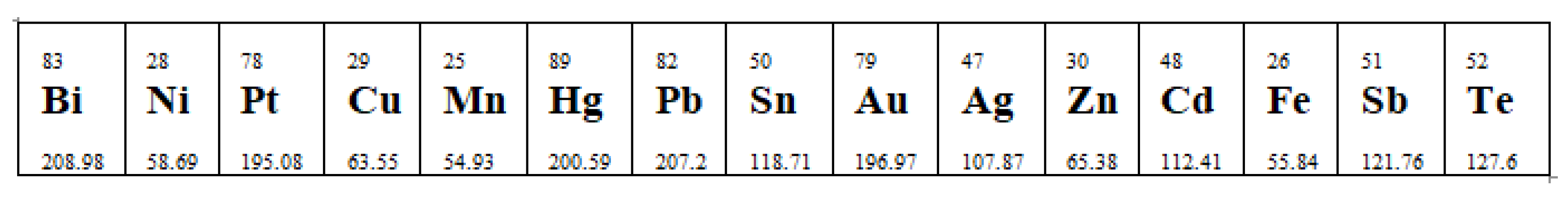
| Thomson’s positive effect | When the current passes from the hot end to the cold end, the heat is developed, so the conductor becomes hot. |
| When the current passes from the cold end to the hot end, the heat is absorbed, so the conductor becomes cold. | |
| Antimony, Silver, Zinc, Cadmium | |
| Thomson’s negative effect | When the current passes from the hot end to the cold end, the heat is absorbed, so the conductor becomes cold. |
| When the current passes from the cold end to the hot end, the heat is evolved, so the conductor becomes hot. | |
| Platinum, Bismuth, Cobalt, Nickel, Mercury. | |
| Thomson’s null effect | Used for the standard metal in thermoelectricity. |
| Lead |
| Year | Research Finding |
|---|---|
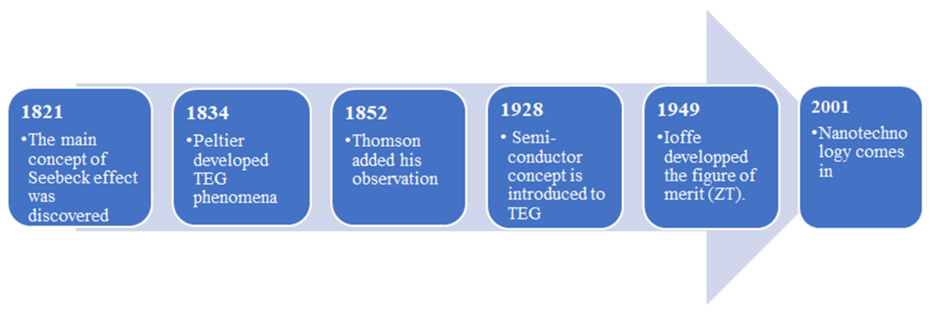
| 1821 | The main concept of Seebeck effect was discovered [54] |
| 1834 | Peltier developed TEG phenomena [55] |
| 1852 | Thomson added his observation [54] |
| 1909 | Altenkirch stated that mathematically, the relationship between the physical properties of thermoelectric materials and the efficiency of a simple TEG [52]. |
| 1911 | Altenkirch (1880–1953) initiated the concept of maximum efficiency of TEG and the performance of a cooler |
| 1928 | Semiconductor concept is introduced in thermoelectric energy [56] |
| 1930 | The first thermoelectric operated radio was stated [56] |
| 1947 | Maria Telkes (1900–1995) built the first thermoelectric power generation of a 5% efficiency [56] |
| 1949 | Abram Fedorovich Ioffe developed the figure of merit (ZT) [52] |
| 1954 | H. Julian Goldsmid froze to 0 °C a surface by a TE Peltier cooler using Bismuth telluride (Bi2Te3) [56] |
| 1968 | The first radioisotope ISNAP19 TEG flew on a NASA spacecraft due to its reliability and remote power generation. Another TE SNAP generator was prepared to travel to the moon in the following year [56]. |
| 1970 * | The healthcare company “Medtronic” prolonged the use of TEGs in the biomedical sector [57]. |
| 1970 | Medtronic has developed the first cardiac pacemaker driven by a TEG and was implanted into a human in France [56]. |
| 1972 | Units of TE cooling were established in Japan for Satellite Communication Ground [58]. |
| 1975 | Lead Telluride (PbTe) TEG technology was formed to generate terrestrial power remotely, forming Global TEG [56]. |
| 1977 | NASA used MHW-RTG3, a Silicon Germanium (SiGe) TEG, to power two voyagers 1 and 2 [56]. |
| 2001 | A noteworthy stepped forward in TEG by introducing nanotechnology scale materials [59,56] |
| 2004 | TEG was integrated into automotive through a program fund by the US Department of Energy and General Motors, like Caterpillar, BMW, and others [60,56] |
| 2005 * | TEG for Industrial Waste Heat Recovery (WHR) was developed [61] |
| 2006 * | Flexible TEG technology [62] |
| 2013 | Voyager 1 developed the first manmade piece powered continuously by TEG to depart the solar system and go into interstellar [56]. |
| Authors | Methodology | Results |
|---|---|---|
| Tabar et al., 2021 [90] | A non-conventional wasted energy recovery system is proposed. This novel framework contains a transformation of excess power, capturing energy loss, helps in reducing pollution and operational cost. | Results obtained assure the ability of the novel design to achieve an almost zero energy configuration, where the environmental pollution and total cost are cut by 170.7% and 83.5% per day, respectively. |
| Babu et al., 2017 [91] | Performance of various solar panel thermal hybrid systems was studied under different configuration such as design, location, TEG junction, additional parameters of design (active or passive cooling), and integration with phase change materials (PCM). Then, the best configurations and future expectation for the PV-TEG design system were presented. | The performance of the PV-TEG system is highly affected by the parameters of TEG results in additional energy that varies from 10% to 20% with overall efficiency that ranges between 40% and 50%. One of the optimum configurations was the hybrid system PV-TEG combined with PCM, which enhances the overall efficiency by 1 to 2%. TEG-PV shows a promising technology for the future; the progress in the TEG can affect significantly any grid networks. |
| Bayendang et al., 2020 [88] | A review of 18 diverse studies on TE and a polymer electrolyte membrane fuel cell (PEMFC) of a hybrid combined cooling heating and power (CCHP) system for domestic/commercial uses was held. To accomplish this, assorted studies on thermoelectricity were investigated. A comparison of TEG and solar energy analysis was held as well. | Results of these studies show that the power efficiency of TE augmented by transforming waste heat into power as for TEGs, and power into cold as for TECs. Furthermore, in TEC and PEMFC hybrid CCHP system, the prime mover was the PEMFC and TEC was the cooler, which was able of producing 2.79 kW of electricity, 26.8 W of cold, and 3.04 kW of heat, resulting in 43.3% of fuel saving and ~77% of total efficiency. The comparison study shows that TEG produces higher power in comparison to solar cells (SC) of equivalent sizes, although more expensive. |
| Darkwa et al., 2019 [86] | Theoretical, numerical, and experimental studies were held on a hybrid system model of TEG that generates limited output power due to small gradient temperature and PCM that has impact on the raise of temperature of the PV through the process of heat storage. The result of different PCM parameters conductivities, thicknesses, and phase change temperatures were calculated. | Simulation results proved the significance of high conductivity of PCM and thickness of PCM layer has impact on layers of TEG and PV. The optimum heat performance for the model PV/TEG/PCM was attained at a 50 mm PCM layer thickness with 5 W/mK thermal conductivity and a phase change temperature that ranges from 40 to 45 °C. |
| Sarveshwar et al., 2018 [92] | A wide investigation for summer and winter solar radiation on the thermodynamics assessment of an irretrievable CPV-TEG cogenerating system was held through different modules Siemens SP75 PV and Bi2Te3 TE, which is commercially accessible. The hybrid system has been demonstrated and simulated to comprehend the viability of the system and to govern the irreversibility’s existent in the hybrid system. | Results displayed that TEG has adversative impact on the hybrid system act and the irreversibility’s rise with growth of concentration ratio, C. In addition, the output power of the hybrid system rises by 86% with the increase in C from 1 to 3 and the efficiency of exergy is greater than the energy efficiency by 8%. The greater values of the irreversibility’s leads to a less inefficient system, thus, substantial developments are required since the higher temperature may lead to formation of hot spots. |
| Ghude et al., 2013 [93] | A study on alternative cooling methods is done, due to the high demand on HVAC and its hazardous effect, where the conventional HVAC system utilizes harmful cooling system that drains the ozone layer. So, the paper presents a comparison study between conventional HVAC and novel cooling system concept HVAC TEC. | Results show that in order to improve conventional HVAC to be ecofriendly requires a long time. Although refrigerant used is HFCs that have lower effect than CFCs over the ozone layer, yet it also affects negatively the ozone layer. On the other hand, HVAC (TEC) model proved superior advantages and better alternative. |
| Patyk 2013 [94] | A study on TEG for improving the efficiency of power generation in ICE and motor generators. Furthermore, a study of environmental and economical values of TEG was held. | Results reveal that TEG saves energy costs and has negligible environmental burden, (eco-efficient). However, it has low production compared to other methods. |
| Hiang et al., 2018 [95] | This paper presents the history and the achievement of TEG development in vehicles during a 7 year program on waste heat recovery incorporating TEG in a BMW X6 and a Lincoln MKT. Throughout this program, several models of TEG were demonstrated, and examined. A comparison analysis on the performance of the vehicle with and without TEG was then concluded. | Results showed that the generated power exceeded 700 W. The Department of Energy (DOE) program was successful, which results in leading a DOE-sponsor of TE WHR program for automotive that is concentrated on declaiming technical and business-related issues. This process is destined to permit TEGs to be more involved in the future automotive products and enhances this field. |
| Zheng et al., 2016 [96] | A simulation of TEG integrated in vehicle power system on ADVISOR software is being modeled by building a relation between the speed of engine and gradient temperature to study the possibility of the TEGs to enhance the fuel efficiency for both conventional vehicles and hybrid electric vehicles (HEVs). The simulations are held out on a conventional automobile and a hybrid TEG-based automobile power structure for 4 representative driving cycles and 6 electrical loads. | The consumption of fuel in both cases were compared and investigated to calculate the fuel economy. Results display that fuel economy was enhanced in both cases, a greater enhancement was noticed in conventional vehicle. Furthermore, an endeavor to integrate TEG more in vehicles is made and an effort is exerted to improve this technology to take bigger share in waste heat recovery fields. |
| Chen et al., 2020 [97] | Experimental and actual study on thermoelectric elevator car air conditioner (TE-ECAC) is held. The performance and cooling characteristics were examined experimentally in an Enthalpy Lab, and the performance of TE-ECAC was enhanced after the analysis. In addition, the weight of TE-ECAC was measured of 10 kg; however conventional air elevator was 38 kg at least. | Results show that ECAC can reach a steady working state at about 200 s. Highest capacity of air-cooling of 324 W and an optimum cooling coefficient of 1.24 can be attained at 1.75 m3/min of the cold side flow rate and 28 °C of ambient temperature. In addition, studies show that TE-ECAC has superior potentials than conventional; where TE-ECAC is much more economical with less weight. |
| Kishore et al., 2020 [98] | Experimental and numerical studies were established to prove the presence of a critical coefficient for heat transfer that drastically impacts the performance of TEGs. In addition, exterior thermal resistances and boundary conditions (BCs) have strong impact on the behavior of TE materials. | Results ensure that BCs effect substantially on the design of TE, where the performance of a TEG differs with the variation of the BCs. For low-grade WHR, the optimized TEG produced 28% greater power and compared to saleable modules optimized, TEG produce 162% greater power per unit mass of TE materials. |
| Shen et al., 2019 [99] | An intensive review on automotive exhaust thermoelectric generators (AETEGs) was held from various perspectives. The feasibility of AETEGs has been demonstrated and a considerable progress has been made. In addition, the review presents some challenges and recommendations that may direct the future work to a great extent such as integrating TEG with some other heat recovery methods and improving TE materials. | Integrating heat pipes (HP) in TEG would offer extra benefits to the system such as enhancing heat transfer to avoid the damage of TEG from high temperature. Integrating phase change materials (PCM) in TEG would offer extra benefits as well and it is worth to be developed and employed commercially, as it protects TEG from damage due to high temperature, uses depleted heat efficiently and decreases the pollutant emission and the fuel consumption. |
| Li et al., 2016 [100] | A simulation study under the same operational conditions on tube and fin heat exchangers (HE) using ANSYS is held. A number of factors were studied such as the variation of the temperature and the Reynolds number. | Both HEs show an agreeable thermal performance with TEG. The fin HE shows better thermal performance due to its compactness. In addition, it displays creation of vortex from the inlet of the pipes to the outlet. Consequently, this structure results in various increases in the temperature even at low Reynolds number. |
| Min et al., 2020 [101] | A mathematical model is established to design a TEG for recovering heat loss from exhaust of a diesel engine. | Results show that the efficiency of the TEG ranges between 1.41% to 4.12%, which is very low. Thus, further improvement should be held. |
| Material’s Requirements | Physical Meaning | Effect on ZT | ||
|---|---|---|---|---|
| High thermoelectric power () | To generate maximum voltage in the circuit. | |||
| High ZT [122] | Power factor | High Seebeck coefficient () [123] | It is the ratio of electromotive force to the gradient temperature between the two sides of the TEG. The material should be of low thermal conductivity and high electrical conductivity. | The power factor affects directly on ZT, the higher power factor, the higher ZT will be. |
| High electrical conductivity (σ) | To decrease losses due to temperature Joule heating. | |||
| Low electrical resistivity (Ω) | ||||
| Operating temperature | The operating or mean temperature. | T affects positively on ZT, which means higher T leads to higher ZT | ||
| Low thermal conductivity (κe) | To minimize the transfer of heat from the hot side to the cold side, thus maintaining a large gradient temperature. | (κL + κe) is inversely proportional to ZT, for instance, as (κL + κe) increase ZT decreases | ||
| Lower scatter phonons (κL) Lattice component | Accumulating phonon scattering decreases thermal conductivity consequently increases ZT. | |||
| Authors | Title | Challenges |
|---|---|---|
| Chen et al., 2012 [164] | Nanostructured thermoelectric materials: Current research and future challenge |
|
| Davis 2018 [165] | A study on TEG materials, applications, and challenges |
|
| Liu et al., 2015 [166] | Current progress and future challenges in thermoelectric power generation: From materials to devices | For device-level development, challenges for metallization conventional TE such as Mg2Si, PbTe, Bi2Te3, CoSb3, and oxides were studied.
|
| Shen et al., 2019 [99] | Automotive exhaust thermoelectric generators: Current status, challenges and future prospects |
|
| Goel et al., 2020 [167] | Polymer Thermoelectric: Opportunities and Challenges | Large gradient temperatures for TE applications, in polymers, are not favorable and thus low-ΔT and power system is required for polymer-based TE, which is suitable for several low-cost uses such as sensors…. These applications do not require high ZT yet they are sensitive to flexibility, cost, and simple in fabrication besides, they require a large voltage output. Consequently, this quest requires higher Seebeck coefficient. |
| Aswa 2016 [168] | Key issues in development of thermoelectric power generators: High figure of merit materials and their highly conducting interfaces with metallic interconnects | This review consists of researches that discussed the evolution of efficient TEGs. The correlating challenges in the discussed researches are classified into:
|
| Shuai et al., 2017 [169] | Recent progress and future challenges on thermoelectric Zintl materials | Practically, there are several challenges in fabricating any module.
|
| O’Dwyer et al., 2017 [170] | Scientific and Technical Challenges in Thermal Transport and Thermoelectric Materials and Devices |
| Advantages | Disadvantages | |
|---|---|---|
| Design [176] |
|
|
| Operations |
|
|
| Materials |
|
|
| Applications |
|
|
Publisher’s Note: MDPI stays neutral with regard to jurisdictional claims in published maps and institutional affiliations. |
© 2021 by the authors. Licensee MDPI, Basel, Switzerland. This article is an open access article distributed under the terms and conditions of the Creative Commons Attribution (CC BY) license (https://creativecommons.org/licenses/by/4.0/).
Share and Cite
Aridi, R.; Faraj, J.; Ali, S.; Lemenand, T.; Khaled, M. Thermoelectric Power Generators: State-of-the-Art, Heat Recovery Method, and Challenges. Electricity 2021, 2, 359-386. https://doi.org/10.3390/electricity2030022
Aridi R, Faraj J, Ali S, Lemenand T, Khaled M. Thermoelectric Power Generators: State-of-the-Art, Heat Recovery Method, and Challenges. Electricity. 2021; 2(3):359-386. https://doi.org/10.3390/electricity2030022
Chicago/Turabian StyleAridi, Rima, Jalal Faraj, Samer Ali, Thierry Lemenand, and Mahmoud Khaled. 2021. "Thermoelectric Power Generators: State-of-the-Art, Heat Recovery Method, and Challenges" Electricity 2, no. 3: 359-386. https://doi.org/10.3390/electricity2030022